EP2501206B1 - Lighting device for a motor vehicle with a redundant control of light sources - Google Patents
Lighting device for a motor vehicle with a redundant control of light sources Download PDFInfo
- Publication number
- EP2501206B1 EP2501206B1 EP12158976.6A EP12158976A EP2501206B1 EP 2501206 B1 EP2501206 B1 EP 2501206B1 EP 12158976 A EP12158976 A EP 12158976A EP 2501206 B1 EP2501206 B1 EP 2501206B1
- Authority
- EP
- European Patent Office
- Prior art keywords
- light source
- light
- group
- switch elements
- lighting device
- Prior art date
- Legal status (The legal status is an assumption and is not a legal conclusion. Google has not performed a legal analysis and makes no representation as to the accuracy of the status listed.)
- Active
Links
Images


Classifications
-
- B—PERFORMING OPERATIONS; TRANSPORTING
- B60—VEHICLES IN GENERAL
- B60Q—ARRANGEMENT OF SIGNALLING OR LIGHTING DEVICES, THE MOUNTING OR SUPPORTING THEREOF OR CIRCUITS THEREFOR, FOR VEHICLES IN GENERAL
- B60Q11/00—Arrangement of monitoring devices for devices provided for in groups B60Q1/00 - B60Q9/00
-
- F—MECHANICAL ENGINEERING; LIGHTING; HEATING; WEAPONS; BLASTING
- F21—LIGHTING
- F21S—NON-PORTABLE LIGHTING DEVICES; SYSTEMS THEREOF; VEHICLE LIGHTING DEVICES SPECIALLY ADAPTED FOR VEHICLE EXTERIORS
- F21S41/00—Illuminating devices specially adapted for vehicle exteriors, e.g. headlamps
- F21S41/60—Illuminating devices specially adapted for vehicle exteriors, e.g. headlamps characterised by a variable light distribution
- F21S41/65—Illuminating devices specially adapted for vehicle exteriors, e.g. headlamps characterised by a variable light distribution by acting on light sources
- F21S41/663—Illuminating devices specially adapted for vehicle exteriors, e.g. headlamps characterised by a variable light distribution by acting on light sources by switching light sources
-
- H—ELECTRICITY
- H05—ELECTRIC TECHNIQUES NOT OTHERWISE PROVIDED FOR
- H05B—ELECTRIC HEATING; ELECTRIC LIGHT SOURCES NOT OTHERWISE PROVIDED FOR; CIRCUIT ARRANGEMENTS FOR ELECTRIC LIGHT SOURCES, IN GENERAL
- H05B45/00—Circuit arrangements for operating light-emitting diodes [LED]
- H05B45/40—Details of LED load circuits
- H05B45/44—Details of LED load circuits with an active control inside an LED matrix
Definitions
- the present invention relates to a lighting device for a motor vehicle with at least one light source which is adapted to generate light from supplied electrical energy, and with a drive circuit which is adapted to an electric current flow through the at least one light source by an actuation of a to control the light source coupled switching element.
- Such a lighting device is for example from the US 2009/0066262 A1 and the DE 10 2008 036 193 A1 as well as from the US 2011/0025215 A1 known.
- the from the DE 10 2008 036 193 A1 known lighting device is a headlight, which uses a plurality of semiconductor light sources for generating a variable, composed of individual light spots, spot light distribution.
- the sum of the light exit surfaces of the LEDs forms a screened light exit surface of the entire LED array, in which each individual LED corresponds to one pixel.
- This variable light distribution is projected by a projection optics as spotlight distribution in the apron of the headlight.
- headlights in which the various light distributions are formed by means of a plurality of light sources, in particular a plurality of semiconductor light sources such as LEDs have drawbacks in the reliability of light generation.
- the probability for an error-free function of a results such a headlamp as a product of the survival probabilities of all interacting elements.
- the probability of survival of an element is considered to be the complement to the probability of failure of the element, the sum of both probabilities for an element being equal to 1. Owing to the large number of factors, an unsatisfactory overall probability for an error-free function then results, even if the survival probabilities of the individual elements involved are large and thus close to 1.
- the light source remains switched on incorrectly. This can be caused by short circuits or interruptions in the control electronics.
- the light source is erroneously turned off, which may also be caused as a result of such short circuits or interruptions or failure of the affected light source.
- the first case is particularly critical for light sources that illuminate fields above a prescribed cut-off.
- the second case is unfavorable in particular for light sources which illuminate fields lying below the prescribed cut-off line and should always be switched on when the dipped beam is switched on.
- the present invention relates to both lights and headlights.
- the term used at the beginning of the lighting device is therefore here as a generic term for Headlamps and lights used.
- An exchange of individual faulty elements is often not possible or only with uneconomical great effort, since modern lighting devices are increasingly housed in largely closed housings that can not be opened without destruction after manufacture. The replacement of complete lighting equipment is also very expensive.
- the object of the invention is to specify a more reliable illumination device with less probability of undesired luminous and / or undesired non-luminous light sources.
- the invention is characterized in that the drive circuit has a plurality of redundant switching elements and is adapted to control the flow of current through a synchronous joint operation of the redundant switching elements, wherein the redundant switching elements are switched on and off together.
- redundant switching elements are understood to mean a plurality of switching elements which act together within the drive circuit and operate with one another in the same way.
- a faulty no longer closing first switching element can be bridged, for example, by a parallel and thus equivalent second switching element. This error of the first switching element then no longer appears.
- the undesirable effect of a fault is constantly closed first switching element, which consists in that the associated current path is not opened, avoided by a second switching element, which is in series with the first switching element and provides the desired interruption of the current path.
- a plurality of switching elements that act together in the drive circuit and function equally with one another are understood to be at least two switching elements, one of which is not required in trouble-free operation.
- Parallel switching elements are then redundant, if one can take away in the error-free state, without changing the function of the circuit.
- In-line switching elements are then redundant, if one can recover in the fault-free state of a through a Leiter Glachen, without changing the function of the circuit.
- An advantageous embodiment is characterized in that the drive circuit is connected in parallel to the light source.
- this embodiment allows a more reliable switch-off or switch-on of the light source.
- an alternative provides that at least two redundant switching elements of the drive circuit are connected in parallel to one another and to the light source. With this alternative, the reliability of the Ausschaltles the light source is increased, because even a desired closed switching element is sufficient to turn off the light source.
- Another alternative provides that at least two redundant switching elements of the drive circuit are connected in series with each other, wherein the series connection of the switching elements is connected in parallel to the light source.
- This embodiment has the advantage that even a desired open switching element is sufficient to turn on the current path via the light source.
- Another embodiment provides that the drive circuit is connected in series with the light source.
- This embodiment also allows a more reliable switch-off or switch-on of the light source, depending on the design of the drive circuit.
- At least two redundant switching elements of the drive circuit are connected in series with each other and with the light source. Then already sufficient a desired closed switching element to turn on the current path via the light source.
- At least two redundant switching elements of the drive circuit are connected in series with each other, wherein the series connection of the switching elements is connected in series with the light source.
- Particularly preferred embodiments provide a combination of series connections and parallel circuits in each case in pairs redundant switching elements.
- Such an embodiment is characterized in that the redundant switching elements have at least a first group of switching elements and at least one second group of switching elements, wherein the first group has switching elements connected in parallel with each other, the second group has switching elements connected in parallel with one another, and the first group and the second group are connected in series with each other.
- This embodiment provides both an increase in the reliability of the Ausschaltiana and an increase in the reliability of the switchability.
- the parallel switching elements of only one of the two groups can be opened at the same time. If the drive circuit with the light source in series, this is reliably turned off. If the drive circuit is parallel to the light source, this is safely energized and thus turned on.
- An alternatively preferred embodiment provides that the redundant switching elements at least a first group of switching elements and at least a second group of switching elements, wherein the first group has mutually connected in series switching elements, the second group having mutually connected in series switching elements, and the first group and the second group are connected in parallel to each other.
- each group only one of the switching elements of this group can be opened. If the drive circuit with the light source in series, this is reliably turned off. If the drive circuit is parallel to the light source, this is safely energized and thus turned on.
- a particularly preferred embodiment is characterized in that the illumination device is a headlight having a plurality of light sources or groups of light sources, which is adapted to generate at least a first light distribution with a first light source or first group of light sources, with only a comparatively small light source Dazzling danger for the Oncoming traffic exists, and with a second light source or group of light sources to produce a second light distribution in which there is a comparatively greater risk of dazzling for oncoming traffic, wherein a light source contributing to the first light distribution has a safely switchable drive circuit, and that a light source contributing to the second light distribution having a safe turn-off drive circuit.
- a law-compliant low beam distribution can be considered, while a high beam distribution can be considered as an example of a second light distribution.
- the full effect of the dipped beam can be maintained even when caused by short circuits or interruptions errors by the redundancy of the drive circuit.
- irregular glare which could occur due to similar errors in the drive electronics of the high-beam light sources, can be effectively avoided.
- the drive circuit has test contacts for each switching element, which enable a contacting of the switching elements during testing of the drive circuit for testing purposes. A failure of reserve elements is otherwise not noticed in the final test.
- components which are connected upstream of the redundant switching elements are also designed to be redundant via additional reserve elements that function identically in each case via the switching elements.
- the shows Fig. 1 a sectional view of a lighting device 10 for a motor vehicle.
- the illumination device 10 has a light module 12 with a matrix-like arrangement of light sources, in particular semiconductor light sources, a primary optics 14 and a secondary optics 16.
- the light module 12 is arranged in a housing 18 of the illumination device 10.
- the housing 18 has a light exit opening, which is covered by a transparent cover 20.
- the matrix-like arrangement of semiconductor light sources is arranged on a circuit board 22 in the illustrated embodiment.
- the circuit board 22 is in a preferred embodiment, a rigid circuit board or a flexible circuit board.
- a flexible circuit board has the advantage that it allows a curved in space, in particular concavely curved connection surface for the semiconductor light sources through which already results in a certain bundling effect.
- rigid circuit boards have the advantage of lower costs and better manageability in the production of the headlamp and greater stability.
- the circuit board is designed as a structural unit with cooling elements for the semiconductor light sources, in order to be able to dissipate reliably the electrical waste heat arising during operation.
- the board 22 also carries the drive circuit, which is implemented in one embodiment as an application-specific integrated circuit. In an alternative embodiment for placement on the board 22, the drive circuit is mounted separately from the board in or on the illumination device and connected via cable to the board 22.
- An optical axis 24 extends substantially horizontally from the arrangement of the semiconductor light sources through the primary optics 14 and the secondary optics 16.
- Fig. 1 shows in this respect a cut along the optical axis 24 lighting device 10 from the side, ie from a direction transverse to the optical axis 24 viewing direction.
- the illumination device is a headlight.
- the invention is also applicable to lights, be it front lights such as daytime running lights, be it rear lights, such as tail lights or brake lights, or be it flashing lights.
- the secondary optics 16 is a projection lens which projects a light distribution which adjusts itself on the light exit surface 26 of the primary optics 14 into the apron of the illumination device 10.
- the light distribution on the light exit surface of the primary optics 14 results as a function of the switching state of the arranged on the board 22 and light in the primary optics 14 feeding semiconductor light sources.
- Fig. 2 shows an embodiment of a primary optics 14 together with an array of semiconductor light sources 28, 30, 32, 34 on the board 22.
- the arrangement preferably comprises more than four semiconductor light sources, of which only four are shown for reasons of clarity.
- the representation is to be understood as a purely schematic representation.
- the semiconductor light sources 28, 30, 32, 34 can be switched on and off individually or in groups, so that their respective influence on the light distribution in front of the vehicle can be selectively activated and deactivated separately from one another.
- LEDs Light-emitting diodes
- the semiconductor light sources have a rectangular or a light exit surface deviating from the rectangular shape due to the desired light distribution and emit light in the color desired for the respective light function or they emit white light.
- white light emitting LEDs are used.
- red light-emitting LEDs can also be used.
- the primary optics 14 has semiconductor light source-individual light guide sections 36, 38, 40, 42 and an interface 52 composed of partial interfaces 44, 46, 48, 50 arranged like a matrix.
- the interface 52 corresponds to the light exit surface 26 of the Fig. 1 ,
- the light guide sections are preferably made of silicone.
- Silicone is a highly transparent material and has a high temperature resistance up to approx. 260 ° C. Heated silicone is particularly thin and can be sprayed during the injection molding in relatively filigree structures. In other embodiments, they consist of glass, plastic or a technically comparable material.
- An optical waveguide section and an associated partial interface are configured to direct light received by an associated semiconductor light source to the secondary optics 16 in a main emission direction.
- Each elongate optical waveguide section is immediately in front of the semiconductor light source or group associated with it
- Semiconductor light sources arranged to receive outgoing light from them.
- the light to be recorded is first coupled by refraction into the interior of the light guide section and then forwarded in the direction of its partial interface mainly by total reflections, which take place at lateral transport surfaces. Due to its special shape, which is characterized by a widening in the direction of light propagation cross-section, and by multiple reflection on the transport walls of the light guide reduces the opening angle of the light beam penetrating it.
- the widening cross-section is preferably achieved by side faces extending in the light propagation direction, which run conically at least in sections and / or are curved in a convex and / or concave manner and thereby define a funnel-shaped structure.
- the transport surfaces of adjacent optical fiber sections approach each other with increasing approach to the partial interfaces.
- the primary optics 14 consists of individual, separate light guide sections or is realized as a one-piece arrangement of light guide sections.
- the light guide sections are optically coupled together at their partial interface side end.
- an optical coupling means that light of a light guide section can leave the primary optics via the partial boundary surface of this light guide section or, in the case of rays directed more towards the side, over the partial boundary surface of adjacent light guide sections.
- the partial boundary surfaces are preferably set up to further reduce the opening angle of the emerging light bundles which reach the subsequent imaging secondary optics 16. Due to the multiple reflection in the optical waveguide sections and due to the further focusing at the partial boundary surfaces, a homogenous luminance distribution is assembled on the interface 52 which has no, or at most strongly suppressed, grating structures and which does not image the spatial separation between the semiconductor light sources.
- neighboring partial interfaces divert inhomogeneities-causing light components away from the imaging secondary optics, so that they can not contribute to the imaging and do not generate disturbing light-dark structures in the light distribution generated on the roadway.
- FIG. 3 shows a light distribution 54, which can be achieved with an array of 63 LEDs in three rows of 21 LEDs, on a lane 57 relative to a horizon 59.
- the light distribution 54 is generated by illumination of many adjacent, sharply demarcated fields 55, each field is preferably illuminated by a single semiconductor light source or a co-operated group of semiconductor light sources. It is preferred that the illumination of the individual fields or groups of fields can be individually switched on and off.
- a light-dark boundary 56 separates one below the light-dark boundary 56 lying bright area of the light distribution 54 of an overlying dark area.
- the light distribution 54 represents a typical light distribution for right-side country light in which the light-dark boundary 56 on the left side is lowered to avoid dazzling oncoming traffic.
- the LEDs belonging to the fields lying above the light-dark boundary 56 may be referred to as glare-critical LEDs, while the remaining LEDs may be referred to as glare-critical LEDs.
- the error to be avoided if possible for glare-critical LEDs is a faulty switched-on state.
- the error to be avoided for anti-glare LEDs, if possible, consists in a faulty switched-off state.
- FIG. 4 illustrates further light distributions, which are adjustable with the object described so far.
- the individually illuminable fields (pixels) are assigned to their position in the resulting light distribution corresponding to different functional groups.
- a light distribution represents a split-beam light distribution 58 for the left side, while other light distributions represent a split-beam light distribution 60 for the right side, a light distribution 62 for illumination of a left turn, a highway light distribution 64 and a light distribution 66 for illumination of a right turn ,
- the respective groups of LEDs involved in the generation of such a light distribution are monitored by monitoring the power consumption and the voltage drop.
- the monitoring is preferably carried out by comparing the detected currents and / or voltages with fault characteristic limit values. It is further preferred that, in the event of a detected fault, the respectively affected functional group is shut down by switching off the supply voltage.
- the FIG. 5 shows a section of a drive circuit for light sources 28, 30, 32, ..., 33, wherein the light sources are preferably semiconductor light sources, in particular light-emitting diodes (LEDs) and wherein the arrow 33 optionally represents existing further light sources.
- the light sources are parallel to one another and are supplied with voltage via a common DC / DC switching regulator 70 and controlled independently of each other via respective light source-individual switching elements 72, 74, 76 and optionally existing further switching elements.
- the switching elements are in the context of the objects presented in this application preferably linear regulators, which generally consist of an actuator, a reference voltage source and an error amplifier.
- the actuator is typically a single transistor or a transistor combination such as a Darlington circuit.
- PWM Pulse Width Modulation
- the DC / DC switching regulator 70 ensures as possible constant, independent of the number of light sources 72, 74, 76, ..., independent voltage drop across these light sources. Each light source therefore has its own switching element in series with it, with which its operating current can be regulated independently of the operating currents of the other light sources.
- FIG. 6 shows a series circuit of light sources 28, 30, ..., 80.
- the series circuit is powered by a DC / DC switching regulator 70 with power.
- light source-individual switching elements 72, 74,..., 82 lying parallel to each light source 28, 30,..., 80, the respective light sources are switched on and off individually.
- the switching elements are controlled by the microcontroller 78. When the switching element is closed, the associated light source is switched off. When the switching element is open, the associated light source is switched on. About a pulse-width modulation of the drive signal, the light sources can be dimmed.
- the drive circuit usually comprises a plurality of groups of LED light sources and thus also a plurality of switching regulators.
- the invention is characterized in that the
- Control circuit in place of exactly one switching element, which is associated with exactly one light source, having a plurality of redundant switching elements and is adapted to control the flow of current through the associated light source by a synchronous operation of the redundant switching elements.
- the light source may have one or more LEDs.
- the two switching elements 86, 88 are actuated by a microcontroller 78.
- the microcontroller 78 is configured to synchronously open and close the n parallel switching elements.
- the control of the synchronous opening and closing can be effected, for example, by jointly controlling the switching elements to be actuated jointly via a single output of the microcontroller 78.
- the number n of the switching elements connected in parallel can also be greater than 2. This also applies to the further embodiments presented in this application.
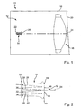
- Such substitution of a single switching element by n parallel and synchronously operated switching elements increases security against accidental switching on the light source 84.
- the light source 84 lights only when both switching elements open correctly. An interruption of one of the two switching elements does not affect the controllability of the light source 84.
- n may be greater than two.
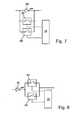
- This circuit increases the security against accidental turning off of the light source 96.
- the light source 96 is turned off only when both switching elements close.
- a short circuit in only one of the two switching elements does not adversely affect the controllability of the light source 96.
- n may be greater than two.
- This circuit has increased security against accidental switching on the light source 102, since the light source 102 only lights up when both switching elements 104, 106 close. For switching off, it is therefore sufficient that only one of the two switching elements 104, 106 opens correctly. A permanent short circuit in only one of the two switching elements 104, 106, however, does not affect the correct controllability of the light source 102.
- n may be greater than two.
- FIG. 11 shows an embodiment in which a single Switching element of a light source has been substituted by a series connection of parallel circuits of switching elements.
- Two switching elements 108 and 110 form a first group of switching elements and two further switching elements 112, 114 form a further group of switching elements.
- the switching elements of the respective group are connected in parallel to each other.
- the first group and the second group are connected in series with each other. It is also possible to use more than two groups and each group can have more than two switching elements.
- FIG. 12 shows an embodiment in which a single switching element of a light source has been substituted by a parallel connection of series circuits of switching elements.
- Two switching elements 116 and 118 form a first group of switching elements and further switching elements 120, 122 form a second group of switching elements.
- the switching elements of a group are connected in series with each other.
- the first and second groups are connected in parallel. It is also possible to use more than two groups and each group can have more than two switching elements.
- Switched light source is thus the circuit after the FIG. 11 better for glare critical light sources, so especially for high beam light sources, suitable.
- the circuit is suitable for the FIG. 12 better with a series-connected light source for glare-critical light sources.
- circuits after the FIG. 11 are more suitable as a substitute for switching elements connected in parallel, as with the objects of the FIGS. 7 and 8 be used.
- Circuits after the FIG. 12 are more suitable as a replacement of series switching elements, as in the case of the objects Figures 9 and 16 are used.
- the reliability of the light module can be further increased, although upstream electronic and electromechanical components, in particular the comparatively vulnerable active electronic components, as well as any existing connectors, redundant running.
- the respective components preferred additional reserve elements are connected in parallel.
- the circuit board on which the drive circuits are preferably arranged together with the light sources, test contacts on which the proper operation of the redundant elements can be checked individually. In this way it can be achieved that printed circuit boards with defective reserve elements, in which the redundancy is no longer guaranteed, are recognized at a tape end inspection at the end of a manufacturing process and not further processed.
- a separate drive circuit is provided in each case for a single light source.
- a plurality of light sources for example different light sources, which are connected together to realize a light function, for example a partial high-beam light function, can be switched together by a single drive circuit.
- the light sources are subdivided into individual switchable individual light sources or light source groups, more than one switching element being provided for the switching of each individual light source or light source group.
- the individual light sources or light source groups are, depending on the configuration, connected in series or in parallel. It is also preferable that, depending on the light functions assigned to the respective light source or light source group, only certain individual light sources or light source groups are equipped with redundant switching elements.
- the light sources are grouped as a function of their photometric function, wherein one or more groups of a common electrical voltage source (DC / DC switching regulator) is supplied and each group can be switched via a common drive circuit. It is also preferred that the supply voltage and / or the current is determined on at least one light source group, in order to detect a malfunction of this light source group, if necessary.
- DC / DC switching regulator common electrical voltage source
Landscapes
- Engineering & Computer Science (AREA)
- Mechanical Engineering (AREA)
- General Engineering & Computer Science (AREA)
- Lighting Device Outwards From Vehicle And Optical Signal (AREA)
Description
Die vorliegende Erfindung betrifft eine Beleuchtungseinrichtung für ein Kraftfahrzeug mit wenigstens einer Lichtquelle, die dazu eingerichtet ist, aus zugeführter elektrischer Energie Licht zu erzeugen, und mit einer Ansteuerschaltung, die dazu eingerichtet ist, einen elektrischen Stromfluss durch die wenigstens eine Lichtquelle durch eine Betätigung eines mit der Lichtquelle gekoppelten Schaltelements zu steuern.The present invention relates to a lighting device for a motor vehicle with at least one light source which is adapted to generate light from supplied electrical energy, and with a drive circuit which is adapted to an electric current flow through the at least one light source by an actuation of a to control the light source coupled switching element.
Eine solche Beleuchtungseinrichtung ist zum Beispiel aus der
Herkömmliche, mit Gasentladungslampen arbeitende Frontscheinwerfer sind in eine Richtung weiterentwickelt worden, in der verschiedene Abblendlichtverteilungen mit verschiedenen Hell-Dunkel-Grenzen wie Landstraßenlicht (schmale Lichtverteilung mit hoher Reichweite), Stadtlicht (breite Lichtverteilung mit niedriger Reichweite), dynamisches Kurvenlicht oder Teilfernlicht durch Schwenken des ganzen Lichtmoduls oder mit motorisch verstellbaren Blenden aus dem Licht einer einzigen Lichtquelle in Form einer Gasentladungslampe erzeugt worden sind.Conventional headlamps employing gas discharge lamps have been further developed in a direction in which different low-beam headlamps have different bright-dark boundaries, such as high-range narrow-beam, city-wide (low-range), dynamic bend, or split-beam, pan entire light module or with motorized aperture from the light of a single light source in the form of a gas discharge lamp have been generated.
Die oben erwähnte
Scheinwerfer, bei denen die verschiedenen Lichtverteilungen mit Hilfe einer Vielzahl von Lichtquellen, insbesondere einer Vielzahl von Halbleiterlichtquellen wie LEDs gebildet werden, weisen jedoch Nachteile bei der Zuverlässigkeit der Lichterzeugung auf. Als Folge des Umstandes, dass in der Regel eine Vielzahl von Lichtquellen und Treiberelementen zur Erzeugung einer Lichtverteilung zusammenwirken müssen, und als Folge des Umstandes, dass die Ausfallwahrscheinlichkeiten der einzelnen Komponenten in erster Näherung voneinander unabhängig sind, ergibt sich die Wahrscheinlichkeit für eine fehlerfreie Funktion eines solchen Scheinwerfers als Produkt der Überlebenswahrscheinlichkeiten aller zusammenwirkenden Elemente. Dabei wird hier unter der Überlebenswahrscheinlichkeit eines Elements das Komplement zur Ausfallwahrscheinlichkeit des Elements betrachtet, wobei die Summe beider Wahrscheinlichkeiten für ein Element gleich 1 ist. Aufgrund der Vielzahl der Faktoren ergibt sich dann eine unbefriedigend kleine Gesamtwahrscheinlichkeit für eine fehlerfreie Funktion, selbst wenn die Überlebenswahrscheinlichkeiten der einzelne beteiligten Elemente große und damit nahe bei 1 liegende Werte besitzen.However, headlights in which the various light distributions are formed by means of a plurality of light sources, in particular a plurality of semiconductor light sources such as LEDs, have drawbacks in the reliability of light generation. As a result of the fact that usually a plurality of light sources and driver elements must cooperate to produce a light distribution, and as a result of the fact that the failure probabilities of the individual components are independent of each other in the first approximation, the probability for an error-free function of a results such a headlamp as a product of the survival probabilities of all interacting elements. Here, the probability of survival of an element is considered to be the complement to the probability of failure of the element, the sum of both probabilities for an element being equal to 1. Owing to the large number of factors, an unsatisfactory overall probability for an error-free function then results, even if the survival probabilities of the individual elements involved are large and thus close to 1.
Ausfälle einer einzelnen Lichtquelle oder eines einzelnen Treibers können zu zwei unterschiedlichen Konsequenzen führen. In einem Fall bleibt die Lichtquelle fehlerhaft eingeschaltet. Dies kann durch Kurzschlüsse oder Unterbrechungen in der Ansteuerelektronik verursacht werden. In einem anderen Fall bleibt die Lichtquelle fehlerhaft ausgeschaltet, was ebenfalls als Folge solcher Kurzschlüsse oder Unterbrechungen oder durch einen Ausfall der betroffenen Lichtquelle verursacht werden kann. Der erste Fall ist besonders kritisch bei Lichtquellen, die oberhalb einer vorgeschriebenen Hell-Dunkel-Grenze liegende Felder beleuchten. Der zweite Fall ist insbesondere bei Lichtquellen ungünstig, die unterhalb der vorgeschriebenen Hell-Dunkel-Grenze liegende Felder beleuchten und bei eingeschaltetem Abblendlicht immer eingeschaltet sein sollten.Failures of a single light source or a single driver can lead to two different consequences. In one case, the light source remains switched on incorrectly. This can be caused by short circuits or interruptions in the control electronics. In another case, the light source is erroneously turned off, which may also be caused as a result of such short circuits or interruptions or failure of the affected light source. The first case is particularly critical for light sources that illuminate fields above a prescribed cut-off. The second case is unfavorable in particular for light sources which illuminate fields lying below the prescribed cut-off line and should always be switched on when the dipped beam is switched on.
Dieses Problem besteht nicht nur bei Frontscheinwerfern, die eine das Vorfeld beleuchtende Lichtverteilung erzeugen sollen, sondern auch bei Kraftfahrzeugleuchten, die andere Verkehrsteilnehmer auf das Kraftfahrzeug und/oder sein Verhalten aufmerksam machen sollen. Dies gilt sowohl für Bugleuchten wie Tagfahrleuchten, die eigentlich immer eingeschaltet sein sollten, als auch für Heckleuchten. Bei Heckleuchten sind zum Beispiel fehlerhaft leuchtende oder fehlerhaft nicht leuchtende Bremsleuchten und Schlussleuchten kritisch. Kritisch sind auch fehlerhaft dauernd oder fehlerhaft nicht leuchtende Blinkleuchten, unabhängig davon, ob es sich um Bug- oder Heckleuchten handelt.This problem exists not only in front headlamps, which should produce a light distribution that illuminates the apron, but also in motor vehicle lights, which should make other road users aware of the motor vehicle and / or its behavior. This applies to both front lights such as daytime running lights, which should always be on, as well as rear lights. For rear lights, for example, incorrectly lit or incorrectly not glowing brake lights and tail lights are critical. Also critical are faulty permanent or faulty non-flashing turn signals, regardless of whether it is a bow or tail lights.
Die vorliegende Erfindung betrifft sowohl Leuchten als auch Scheinwerfer. Der eingangs verwendete Begriff der Beleuchtungseinrichtung wird hier daher als Oberbegriff für Scheinwerfer und Leuchten verwendet. Ein Austausch einzelner fehlerhafter Elemente ist häufig nicht oder nur mit unwirtschaftlich großem Aufwand möglich, da moderne Beleuchtungseinrichtungen zunehmend in weitgehend geschlossenen Gehäusen untergebracht sind, die nach der Herstellung nicht mehr zerstörungsfrei geöffnet werden können. Der Austausch kompletter Beleuchtungseinrichtungen ist ebenfalls sehr teuer.The present invention relates to both lights and headlights. The term used at the beginning of the lighting device is therefore here as a generic term for Headlamps and lights used. An exchange of individual faulty elements is often not possible or only with uneconomical great effort, since modern lighting devices are increasingly housed in largely closed housings that can not be opened without destruction after manufacture. The replacement of complete lighting equipment is also very expensive.
Vor diesem Hintergrund besteht die Aufgabe der Erfindung in der Angabe einer zuverlässigeren Beleuchtungseinrichtung mit geringerer Wahrscheinlichkeit von unerwünscht leuchtenden und/oder unerwünscht nicht leuchtenden Lichtquellen.Against this background, the object of the invention is to specify a more reliable illumination device with less probability of undesired luminous and / or undesired non-luminous light sources.
Diese Aufgabe wird bei einer Beleuchtungseinrichtung der eingangs genannten Art durch die Merkmale des Anspruchs 1 gelöst.This object is achieved in a lighting device of the type mentioned by the features of claim 1.
Die Erfindung zeichnet sich dadurch aus, dass die Ansteuerschaltung mehrere redundante Schaltelemente aufweist und dazu eingerichtet ist, den Stromfluss durch eine synchrone gemeinsame Betätigung der redundanten Schaltelemente zu steuern, wobei die reduntanten Schaltelemente jeweils gemeinsam eingeschaltet und ausgeschaltet werden.The invention is characterized in that the drive circuit has a plurality of redundant switching elements and is adapted to control the flow of current through a synchronous joint operation of the redundant switching elements, wherein the redundant switching elements are switched on and off together.
Dabei wird unter redundanten Schaltelementen eine Mehrzahl von innerhalb der Ansteuerschaltung zusammen und untereinander gleich wirkenden Schaltelementen verstanden. Ein fehlerhaft nicht mehr schließendes erstes Schaltelement kann zum Beispiel durch ein parallel liegendes und damit gleichwirkendes zweites Schaltelement überbrückt werden. Dieser Fehler des ersten Schaltelements tritt dann nicht mehr in Erscheinung. In einen anderem Beispiel wird die unerwünschte Wirkung eines fehlerhaft dauernd geschlossenen ersten Schaltelements, die darin besteht, dass der zugehörige Strompfad nicht geöffnet wird, durch ein zweites Schaltelement vermieden, das in Reihe mit dem ersten Schaltelement liegt und für die gewünschte Unterbrechung des Strompfades sorgt.In this case, redundant switching elements are understood to mean a plurality of switching elements which act together within the drive circuit and operate with one another in the same way. A faulty no longer closing first switching element can be bridged, for example, by a parallel and thus equivalent second switching element. This error of the first switching element then no longer appears. In another example, the undesirable effect of a fault is constantly closed first switching element, which consists in that the associated current path is not opened, avoided by a second switching element, which is in series with the first switching element and provides the desired interruption of the current path.
Unter mehreren innerhalb der Ansteuerschaltung zusammen und untereinander gleich wirkenden Schaltelementen werden dabei mindestens zwei Schaltelemente verstanden, von denen eines bei einem störungsfreien Betrieb nicht benötigt wird. Parallel zueinander liegende Schaltelemente sind dann redundant, wenn man im fehlerfreien Zustand eines wegnehmen kann, ohne die Funktion der Schaltung zu verändern. In Reihe liegende Schaltelemente sind dann redundant, wenn man im fehlerfreien Zustand eines durch ein Leiterstückchen erstetzen kann, ohne die Funktion der Schaltung zu ändern.In this context, a plurality of switching elements that act together in the drive circuit and function equally with one another are understood to be at least two switching elements, one of which is not required in trouble-free operation. Parallel switching elements are then redundant, if one can take away in the error-free state, without changing the function of the circuit. In-line switching elements are then redundant, if one can recover in the fault-free state of a through a Leiterstückchen, without changing the function of the circuit.
Eine vorteilhafte Ausgestaltung zeichnet sich dadurch aus, dass die Ansteuerschaltung parallel zu der Lichtquelle geschaltet ist.An advantageous embodiment is characterized in that the drive circuit is connected in parallel to the light source.
Je nach Ausgestaltung der Ansteuerschaltung erlaubt diese Ausgestaltung eine zuverlässigere Ausschaltbarkeit oder Einschaltbarkeit der Lichtquelle.Depending on the configuration of the drive circuit, this embodiment allows a more reliable switch-off or switch-on of the light source.
Dabei sieht eine Alternative vor, dass wenigstens zwei redundante Schaltelemente der Ansteuerschaltung zueinander und zu der Lichtquelle parallel geschaltet sind. Mit dieser Alternative wird die Zuverlässigkeit der Ausschaltbarkeit der Lichtquelle erhöht, weil bereits ein gewünscht geschlossenes Schaltelement ausreicht, um die Lichtquelle stromlos zu schalten.In this case, an alternative provides that at least two redundant switching elements of the drive circuit are connected in parallel to one another and to the light source. With this alternative, the reliability of the Ausschaltbarkeit the light source is increased, because even a desired closed switching element is sufficient to turn off the light source.
Eine weitere Alternative sieht vor, dass wenigstens zwei redundante Schaltelemente der Ansteuerschaltung in Reihe zueinander geschaltet sind, wobei die Reihenschaltung der Schaltelemente parallel zu der Lichtquelle geschaltet ist. Diese Ausgestaltung hat den Vorteil, dass bereits ein gewünscht offenes Schaltelement ausreicht, um den Strompfad über die Lichtquelle einzuschalten.Another alternative provides that at least two redundant switching elements of the drive circuit are connected in series with each other, wherein the series connection of the switching elements is connected in parallel to the light source. This embodiment has the advantage that even a desired open switching element is sufficient to turn on the current path via the light source.
Eine andere Ausgestaltung sieht vor, dass die Ansteuerschaltung in Reihe zu der Lichtquelle geschaltet ist.Another embodiment provides that the drive circuit is connected in series with the light source.
Auch diese Ausgestaltung erlaubt je nach Ausgestaltung der Ansteuerschaltung eine zuverlässigere Ausschaltbarkeit oder Einschaltbarkeit der Lichtquelle.This embodiment also allows a more reliable switch-off or switch-on of the light source, depending on the design of the drive circuit.
Für eine zuverlässige Einschaltbarkeit ist bevorzugt, dass wenigstens zwei redundante Schaltelemente der Ansteuerschaltung parallel zueinander und zu der Lichtquelle in Reihe geschaltet sind. Dann reicht bereits ein gewünscht geschlossenes Schaltelement aus, um den Strompfad über die Lichtquelle einzuschalten.For reliable turn-on it is preferred that at least two redundant switching elements of the drive circuit are connected in series with each other and with the light source. Then already sufficient a desired closed switching element to turn on the current path via the light source.
Für eine zuverlässigere Ausschaltbarkeit ist bevorzugt, dass wenigstens zwei redundante Schaltelemente der Ansteuerschaltung in Reihe zueinander geschaltet sind, wobei die Reihenschaltung der Schaltelemente in Reihe zu der Lichtquelle geschaltet ist. Die sicherere Ausschaltbarkeit ergibt sich hier dadurch, dass bereits ein gewünscht offenes Schaltelement ausreicht, um die Lichtquelle stromlos zu schalten.For more reliable turn-off capability, it is preferred that at least two redundant switching elements of the drive circuit are connected in series with each other, wherein the series connection of the switching elements is connected in series with the light source. The safer switch-off results here in that already a desired open switching element is sufficient to switch the light source without power.
Besonders bevorzugte Ausgestaltungen sehen eine Kombination von Reihenschaltungen und Parallelschaltungen jeweils paarweise redundanter Schaltelemente vor.Particularly preferred embodiments provide a combination of series connections and parallel circuits in each case in pairs redundant switching elements.
Eine solche Ausgestaltung zeichnet sich dadurch aus, dass die redundanten Schaltelemente wenigstens eine erste Gruppe von Schaltelementen und wenigstens eine zweite Gruppe von Schaltelementen aufweisen, wobei die erste Gruppe untereinander parallel geschaltete Schaltelemente aufweist, die zweite Gruppe untereinander parallel geschaltete Schaltelemente aufweist, und die erste Gruppe und die zweite Gruppe zueinander in Reihe geschaltet sind. Diese Ausgestaltung ergibt sowohl eine Steigerung der Zuverlässigkeit der Ausschaltbarkeit als auch eine Steigerung der Zuverlässigkeit der Einschaltbarkeit.Such an embodiment is characterized in that the redundant switching elements have at least a first group of switching elements and at least one second group of switching elements, wherein the first group has switching elements connected in parallel with each other, the second group has switching elements connected in parallel with one another, and the first group and the second group are connected in series with each other. This embodiment provides both an increase in the reliability of the Ausschaltbarkeit and an increase in the reliability of the switchability.
Um sicher Strom zu führen, reicht es bei einer solchen Ansteuerschaltung aus, dass lediglich ein Schaltelement jeder Gruppe geschlossen werden kann. Liegt die Ansteuerschaltung mit der Lichtquelle in Reihe, wird diese dadurch zuverlässig eingeschaltet. Liegt die Ansteuerschaltung parallel zu der Lichtquelle, wird diese dadurch sicher stromlos und damit ausgeschaltet.To safely carry power, it is sufficient in such a drive circuit that only one switching element of each group can be closed. If the drive circuit with the light source in series, this is reliably turned on. If the drive circuit is parallel to the light source, this is safely de-energized and thus off.
Um sicher keinen Strom zu führen, reicht es aus dass die parallel liegenden Schaltelemente von lediglich einer der beiden Gruppen zeitgleich geöffnet werden können. Liegt die Ansteuerschaltung mit der Lichtquelle in Reihe, wird diese dadurch zuverlässig ausgeschaltet. Liegt die Ansteuerschaltung parallel zu der Lichtquelle, wird diese dadurch sicher stromführend und damit eingeschaltet.To ensure safe power, it is sufficient that the parallel switching elements of only one of the two groups can be opened at the same time. If the drive circuit with the light source in series, this is reliably turned off. If the drive circuit is parallel to the light source, this is safely energized and thus turned on.
Eine alternativ bevorzugte Ausgestaltung sieht vor, dass die redundanten Schaltelemente wenigstens eine erste Gruppe von Schaltelementen und wenigstens eine zweite Gruppe von Schaltelementen aufweisen, wobei die erste Gruppe untereinander in Serie geschaltete Schaltelemente aufweist, die zweite Gruppe untereinander in Serie geschaltete Schaltelemente aufweist, und die erste Gruppe und die zweite Gruppe zueinander parallel geschaltet sind.An alternatively preferred embodiment provides that the redundant switching elements at least a first group of switching elements and at least a second group of switching elements, wherein the first group has mutually connected in series switching elements, the second group having mutually connected in series switching elements, and the first group and the second group are connected in parallel to each other.
Auch diese Ausgestaltung ergibt sowohl eine Steigerung der Zuverlässigkeit der Ausschaltbarkeit als auch eine Steigerung der Zuverlässigkeit der Einschaltbarkeit.This refinement also results in an increase in the reliability of the disconnectability as well as an increase in the reliability of the switch-on capability.
Um sicher Strom zu führen, reicht es bei einer solchen Ansteuerschaltung aus, dass lediglich beide Schaltelemente einer Gruppe geschlossen werden können. Liegt die Ansteuerschaltung mit der Lichtquelle in Reihe, wird diese dadurch zuverlässig eingeschaltet. Liegt die Ansteuerschaltung parallel zu der Lichtquelle, wird diese dadurch sicher stromlos und damit ausgeschaltet.To safely carry power, it is sufficient in such a drive circuit that only both switching elements of a group can be closed. If the drive circuit with the light source in series, this is reliably turned on. If the drive circuit is parallel to the light source, this is safely de-energized and thus off.
Um sicher keinen Strom zu führen, reicht es aus dass in jeder Gruppe lediglich eines der Schaltelemente dieser Gruppe geöffnet werden kann. Liegt die Ansteuerschaltung mit der Lichtquelle in Reihe, wird diese dadurch zuverlässig ausgeschaltet. Liegt die Ansteuerschaltung parallel zu der Lichtquelle, wird diese dadurch sicher stromführend und damit eingeschaltet.To ensure safe power, it is sufficient that in each group only one of the switching elements of this group can be opened. If the drive circuit with the light source in series, this is reliably turned off. If the drive circuit is parallel to the light source, this is safely energized and thus turned on.
Eine besonders bevorzugte Ausgestaltung zeichnet sich dadurch aus, dass die Beleuchtungseinrichtung ein mehrere Lichtquellen oder Gruppen von Lichtquellen aufweisender Frontscheinwerfer ist, der dazu eingerichtet ist, mit einer ersten Lichtquelle oder ersten Gruppe von Lichtquellen wenigstens eine erste Lichtverteilung zu erzeugen, bei der nur eine vergleichsweise geringe Blendungsgefahr für den Gegenverkehr besteht, und mit einer zweiten Lichtquelle oder Gruppe von Lichtquellen eine zweite Lichtverteilung zu erzeugen, bei der eine vergleichsweise größere Blendgefahr für den Gegenverkehr besteht, wobei eine zur ersten Lichtverteilung beitragende Lichtquelle eine sicher einschaltbare Ansteuerschaltung aufweist, und dass eine zur zweiten Lichtverteilung beitragende Lichtquelle eine sicher ausschaltbare Ansteuerschaltung aufweist.A particularly preferred embodiment is characterized in that the illumination device is a headlight having a plurality of light sources or groups of light sources, which is adapted to generate at least a first light distribution with a first light source or first group of light sources, with only a comparatively small light source Dazzling danger for the Oncoming traffic exists, and with a second light source or group of light sources to produce a second light distribution in which there is a comparatively greater risk of dazzling for oncoming traffic, wherein a light source contributing to the first light distribution has a safely switchable drive circuit, and that a light source contributing to the second light distribution having a safe turn-off drive circuit.
Als Beispiel einer ersten Lichtverteilung kann eine gesetzeskonforme Abblendlichtverteilung betrachtet werden, während eine Fernlichtverteilung als Beispiel einer zweiten Lichtverteilung betrachtet werden kann. Durch diese Ausgestaltung kann die volle Wirkung des Abblendlichtes auch bei durch Kurzschlüsse oder Unterbrechungen verursachten Fehlern durch die Redundanz der Ansteuerschaltung aufrechterhalten werden. Eine regelwidrige Blendung, wie sie durch ähnliche Fehler in der Ansteuerelektronik der Fernlicht-Lichtquellen auftreten könnte, kann dagegen wirksam vermieden werden.As an example of a first light distribution, a law-compliant low beam distribution can be considered, while a high beam distribution can be considered as an example of a second light distribution. By this configuration, the full effect of the dipped beam can be maintained even when caused by short circuits or interruptions errors by the redundancy of the drive circuit. On the other hand, irregular glare, which could occur due to similar errors in the drive electronics of the high-beam light sources, can be effectively avoided.
Bevorzugt ist auch, dass die Ansteuerschaltung für jedes Schaltelement Prüfkontakte aufweist, die eine zu Prüfzwecken erfolgende Kontaktierung der Schaltelemente bei der Fertigung der Ansteuerschaltung ermöglichen. Ein Ausfall von Reserveelementen wird sonst in der Endprüfung nicht bemerkt.It is also preferable that the drive circuit has test contacts for each switching element, which enable a contacting of the switching elements during testing of the drive circuit for testing purposes. A failure of reserve elements is otherwise not noticed in the final test.
Bevorzugt ist auch, dass über die Schaltelemente hinaus den redundanten Schaltelementen vorgeschaltete Bauelemente, insbesondere aktive elektronische Bauelemente und Steckverbindungen durch zusätzliche funktionsmäßig jeweils gleichwirkende Reserveelemente ebenfalls redundant ausgeführt sind.It is also preferable that components which are connected upstream of the redundant switching elements, in particular active electronic components and plug-in connections, are also designed to be redundant via additional reserve elements that function identically in each case via the switching elements.
Weitere Vorteile ergeben sich aus den abhängigen Ansprüchen, der Beschreibung und den beigefügten Figuren.Further advantages will be apparent from the dependent claims, the description and the attached figures.
Es versteht sich, dass die vorstehend genannten und die nachstehend noch zu erläuternden Merkmale nicht nur in der jeweils angegeben Kombination, sondern auch in anderen Kombinationen oder in Alleinstellung verwendbar sind, ohne den Rahmen der vorliegenden Erfindung zu verlassen.It is understood that the features mentioned above and those yet to be explained below can be used not only in the combination indicated, but also in other combinations or in isolation, without departing from the scope of the present invention.
Ausführungsbeispiele der Erfindung sind in den Zeichnungen dargestellt und werden in der nachfolgenden Beschreibung näher erläutert. Dabei zeigen, jeweils in schematischer Form:
- Fig. 1
- eine Schnittdarstellung einer Beleuchtungseinrichtung für ein Kraftfahrzeug;
- Fig. 2
- eine Ausgestaltung einer Primäroptik der Beleuchtungseinrichtung zusammen mit einer Anordnung von Halbleiterlichtquellen;
- Fig. 3
eine Lichtverteilung 54, die sich mit einer Beleuchtungseinrichtung nach denFig. 1 und 2 einstellen lässt;- Fig. 4
- weitere Lichtverteilungen, die mit dem Gegenstand der
Fig. 1 und 2 einstellbar sind; - Fig. 5
- einen Ausschnitt aus einer Ansteuerschaltung für parallel zueinander liegende Lichtquellen;
- Fig. 6
- einen Ausschnitt aus einer Ansteuerschaltung für in Reihe geschaltete Lichtquellen;
- Fig. 7
- eine Ausgestaltung einer Ansteuerung einer Lichtquelle mit erhöhter Sicherheit gegen ein ungewolltes Einschalten der Lichtquelle;
- Fig. 8
- eine Ausgestaltung einer Ansteuerung einer Lichtquelle zur Erhöhung der Sicherheit gegen ein ungewolltes Ausschalten der Lichtquelle;
- Fig. 9
- eine Ausgestaltung mit erhöhter Sicherheit gegen ein ungewolltes Ausschalten der Lichtquelle;
- Fig. 10
- eine Ausgestaltung, die eine erhöhte Sicherheit gegen ein ungewolltes Einschalten der Lichtquelle liefert;
- Fig. 11
- eine Ausgestaltung, bei der ein einzelnes Schaltelement durch eine Reihenschaltung von Parallelschaltungen von Schaltelementen substituiert worden ist; und
- Fig. 12
- eine Ausgestaltung, bei der ein einzelnes Schaltelement durch eine Parallelschaltung von Reihenschaltungen substituiert worden ist.
- Fig. 1
- a sectional view of a lighting device for a motor vehicle;
- Fig. 2
- an embodiment of a primary optics of the illumination device together with an array of semiconductor light sources;
- Fig. 3
- a
light distribution 54, which deals with a lighting device according to theFig. 1 and 2 can be set; - Fig. 4
- other light distributions associated with the subject matter of
Fig. 1 and 2 are adjustable; - Fig. 5
- a section of a drive circuit for mutually parallel light sources;
- Fig. 6
- a section of a drive circuit for series-connected light sources;
- Fig. 7
- an embodiment of a control of a light source with increased security against accidental switching on of the light source;
- Fig. 8
- an embodiment of a control of a light source to increase security against accidental turning off the light source;
- Fig. 9
- an embodiment with increased security against accidental switching off the light source;
- Fig. 10
- an embodiment that provides increased security against accidental switching on the light source;
- Fig. 11
- an embodiment in which a single switching element has been substituted by a series connection of parallel circuits of switching elements; and
- Fig. 12
- an embodiment in which a single switching element has been substituted by a parallel connection of series circuits.
Dabei bezeichnen gleiche Bezugszeichen in verschiedenen Figuren jeweils gleiche oder zumindest ihrer Funktion nach gleiche Elemente.In this case, the same reference symbols in different figures denote the same or at least functionally identical elements.
Im Einzelnen zeigt die
Das Lichtmodul 12 ist in einem Gehäuse 18 der Beleuchtungseinrichtung 10 angeordnet. Das Gehäuse 18 weist eine Lichtaustrittsöffnung auf, die von einer transparenten Abdeckscheibe 20 abgedeckt wird. Die matrixartige Anordnung von Halbleiterlichtquellen ist in der dargestellten Ausgestaltung auf einer Platine 22 angeordnet.The
Die Platine 22 ist in einer bevorzugten Ausgestaltung eine starre Leiterplatte oder eine flexible Leiterplatte. Eine flexible Leiterplatte hat den Vorteil, dass sie eine im Raum gekrümmte, insbesondere konkav gekrümmte Anschlussfläche für die Halbleiterlichtquellen erlaubt, durch die sich bereits eine gewisse bündelnde Wirkung ergibt. Starre Leiterplatten besitzen dagegen den Vorteil geringerer Kosten und einer besseren Handhabbarkeit bei der Herstellung des Scheinwerfers und einer größeren Stabilität.The
Bevorzugt ist auch, dass die Platine als bauliche Einheit mit Kühlelementen für die Halbleiterlichtquellen ausgestaltet ist, um die im Betrieb anfallende elektrische Verlustwärme zuverlässig abführen zu können. Darüber hinaus ist bevorzugt, dass die Platine 22 auch die Ansteuerschaltung trägt, die in einer Ausgestaltung als anwendungsspezifische integrierte Schaltung realisiert ist. In einer zur Unterbringung auf der Platine 22 alternativen Ausgestaltung ist die Ansteuerschaltung getrennt von der Platine in oder an der Beleuchtungseinrichtung angebracht und über Kabel mit der Platine 22 verbunden.It is also preferred that the circuit board is designed as a structural unit with cooling elements for the semiconductor light sources, in order to be able to dissipate reliably the electrical waste heat arising during operation. In addition, it is preferred that the
Eine optische Achse 24 erstreckt sich im Wesentlichen horizontal von der Anordnung der Halbleiterlichtquellen ausgehend durch die Primäroptik 14 und die Sekundäroptik 16 hindurch.
Die folgende Erläuterung bezieht sich auf eine Ausgestaltung der Beleuchtungseinrichtung 10 als Scheinwerfer. Wegen des Bezuges auf Scheinwerfer wird in der folgenden Erläuterung auch auf Merkmale Bezug genommen, die nicht wesentlich für die von der Ausgestaltung als Scheinwerfer abstrahierte Erfindung sind. Die für die Erfindung wesentlichen Merkmale sind im Anspruch 1 zusammengefasst.The following explanation refers to an embodiment of the
Bei der Sekundäroptik 16 handelt es sich in der dargestellten Ausgestaltung um eine Projektionslinse, die eine sich auf der Lichtaustrittsfläche 26 der Primäroptik 14 einstellende Lichtverteilung in das Vorfeld der Beleuchtungseinrichtung 10 projiziert. Dabei ergibt sich die Lichtverteilung auf der Lichtaustrittsfläche der Primäroptik 14 in Abhängigkeit vom Schaltzustand der auf der Platine 22 angeordneten und Licht in die Primäroptik 14 einspeisenden Halbleiterlichtquellen.In the illustrated embodiment, the
Als Halbleiterlichtquellen werden in einer Ausgestaltung Leuchtdioden (LEDs) verwendet. Die Halbleiterlichtquellen besitzen je nach Ausgestaltung eine rechteckige oder eine aufgrund der gewünschten Lichtverteilung von der Rechteckform abweichende Lichtaustrittsfläche und emittieren Licht in der für die jeweilige Lichtfunktion gewünschten Farbe, oder sie emittieren weißes Licht. Wenn die Beleuchtungseinrichtung ein Scheinwerfer ist, werden weißes Licht emittierende LEDs verwendet. Ist die die Beleuchtungseinrichtung dagegen eine Heckleuchte, können auch rotes Licht emittierende LEDs verwendet werden.As semiconductor light sources are in one embodiment Light-emitting diodes (LEDs) used. Depending on the embodiment, the semiconductor light sources have a rectangular or a light exit surface deviating from the rectangular shape due to the desired light distribution and emit light in the color desired for the respective light function or they emit white light. When the lighting device is a headlight, white light emitting LEDs are used. On the other hand, if the lighting device is a taillight, red light-emitting LEDs can also be used.
Die Primäroptik 14 weist in der dargestellten Ausgestaltung Halbleiterlichtquellen-individuelle Lichtleiterabschnitte 36, 38, 40, 42 und eine aus matrixartig angeordneten Teilgrenzflächen 44, 46, 48, 50 zusammengesetzte Grenzfläche 52 auf. Die Grenzfläche 52 entspricht der Lichtaustrittsfläche 26 aus der
Die Lichtleiterabschnitte sind bevorzugt aus Silikon hergestellt. Silikon ist ein hochtransparentes Material und weist eine hohe Temperaturbeständigkeit bis ca. 260°C auf. Erhitztes Silikon ist besonders dünnflüssig und kann so während des Spritzgießverfahrens auch in relativ filigrane Strukturen gespritzt werden. In anderen Ausgestaltungen bestehen sie aus Glas, Kunststoff oder einem technisch vergleichbaren Material. Ein Lichtleiterabschnitt und eine zugehörige Teilgrenzfläche sind dazu eingerichtet, von einer zugehörigen Halbleiterlichtquelle aufgenommenes Licht in einer Hauptabstrahlrichtung auf die Sekundäroptik 16 zu richten.The light guide sections are preferably made of silicone. Silicone is a highly transparent material and has a high temperature resistance up to approx. 260 ° C. Heated silicone is particularly thin and can be sprayed during the injection molding in relatively filigree structures. In other embodiments, they consist of glass, plastic or a technically comparable material. An optical waveguide section and an associated partial interface are configured to direct light received by an associated semiconductor light source to the
Jeder längliche Lichtleiterabschnitt ist mit seinem seiner Teilgrenzfläche gegenüberliegenden Ende unmittelbar vor der ihm zugeordneten Halbleiterlichtquelle oder Gruppe von Halbleiterlichtquellen angeordnet, um von diesen ausgehendes Licht aufzunehmen. Das aufzunehmende Licht wird zunächst durch Brechung in das Innere des Lichtleiterabschnittes eingekoppelt und dann vorwiegend durch Totalreflexionen, die an seitlichen Transportflächen erfolgen, in Richtung seiner Teilgrenzfläche weitergeleitet. Durch seine besondere Form, die sich durch einen sich in Lichtausbreitungsrichtung aufweitenden Querschnitt auszeichnet, und durch Mehrfachreflexion an den Transportwänden reduziert der Lichtleiter den Öffnungswinkel des ihn durchdringenden Lichtbündels.Each elongate optical waveguide section, with its end opposite its partial interface, is immediately in front of the semiconductor light source or group associated with it Semiconductor light sources arranged to receive outgoing light from them. The light to be recorded is first coupled by refraction into the interior of the light guide section and then forwarded in the direction of its partial interface mainly by total reflections, which take place at lateral transport surfaces. Due to its special shape, which is characterized by a widening in the direction of light propagation cross-section, and by multiple reflection on the transport walls of the light guide reduces the opening angle of the light beam penetrating it.
Der sich aufweitende Querschnitt wird bevorzugt durch in Lichtausbreitungsrichtung verlaufende Seitenflächen erzielt, die zumindest abschnittsweise konisch verlaufen und/oder konvex und/oder konkav gekrümmt sind und dabei eine trichterförmige Struktur definieren.The widening cross-section is preferably achieved by side faces extending in the light propagation direction, which run conically at least in sections and / or are curved in a convex and / or concave manner and thereby define a funnel-shaped structure.
In der dargestellten Ausgestaltung nähern sich die Transportflächen benachbarter Lichtleiterabschnitte mit zunehmender Annäherung an die Teilgrenzflächen aneinander an. Je nach Ausgestaltung besteht die Primäroptik 14 aus einzelnen, getrennten Lichtleiterabschnitten oder ist als einstückige Anordnung von Lichtleiterabschnitten realisiert.In the illustrated embodiment, the transport surfaces of adjacent optical fiber sections approach each other with increasing approach to the partial interfaces. Depending on the configuration, the
In jedem Fall ist bevorzugt, dass die Lichtleiterabschnitte an ihrem Teilgrenzflächen-seitigen Ende optisch miteinander gekoppelt sind. Dabei wird unter einer optischen Kopplung verstanden, dass Licht eines Lichtleiterabschnitts die Primäroptik über die Teilgrenzfläche dieses Lichtleiterabschnitts oder, bei stärker zur Seite gerichteten Strahlen, über die Teilgrenzfläche benachbarter Lichtleiterabschnitte verlassen kann.In any case, it is preferred that the light guide sections are optically coupled together at their partial interface side end. In this case, an optical coupling means that light of a light guide section can leave the primary optics via the partial boundary surface of this light guide section or, in the case of rays directed more towards the side, over the partial boundary surface of adjacent light guide sections.
Die Teilgrenzflächen sind bevorzugt dazu eingerichtet, die Öffnungswinkel der austretenden Lichtbündel, die in die nachfolgende, abbildende Sekundäroptik 16 gelangen, noch weiter zu verkleinern. Durch die Mehrfachreflexion in den Lichtleiterabschnitten und durch die weitere Bündelung an den Teilgrenzflächen wird eine homogene Leuchtdichteverteilung auf der Grenzfläche 52 zusammengefügt, die keine, oder höchstens stark unterdrückte, Gitterstrukturen aufweist und die die räumliche Trennung zwischen den Halbleiterlichtquellen nicht abbildet.The partial boundary surfaces are preferably set up to further reduce the opening angle of the emerging light bundles which reach the subsequent imaging
Gleichzeitig lenken jeweils benachbarte Teilgrenzflächen Inhomogenitäten verursachende Lichtanteile von der abbildenden Sekundäroptik weg, so dass diese nicht zur Abbildung beitragen können und keine störenden Hell-Dunkel-Strukturen in der auf der Fahrbahn erzeugten Lichtverteilung generieren.At the same time, neighboring partial interfaces divert inhomogeneities-causing light components away from the imaging secondary optics, so that they can not contribute to the imaging and do not generate disturbing light-dark structures in the light distribution generated on the roadway.
In der dargestellten Ausgestaltung trennt eine Hell-Dunkel-Grenze 56 einen unterhalb der Hell-Dunkel-Grenze 56 liegenden hellen Bereich der Lichtverteilung 54 von einem darüber liegenden dunklen Bereich. Die Lichtverteilung 54 stellt eine typische Lichtverteilung für Landstraßen-Licht bei Rechtsverkehr dar, bei der die Hell-Dunkel-Grenze 56 auf der linken Seite abgesenkt ist, um eine Blendung des Gegenverkehrs zu vermeiden. Insofern können die LEDs die zu oberhalb der Hell-Dunkel-Grenze 56 liegenden Feldern gehören, als blendungskritische LEDs bezeichnet werden, während die übrigen LEDs als blendungsunkritische LEDs bezeichnet werden können. Der für blendungskritische LEDs nach Möglichkeit zu vermeidende Fehler besteht in einem fehlerhaft eingeschalteten Zustand. Der für blendungsunkritische LEDs nach Möglichkeit zu vermeidende Fehler besteht in einem fehlerhaft ausgeschalteten Zustand.In the illustrated embodiment, a light-
Durch selektives Einschalten und Ausschalten der den verschiedenen Feldern zugeordneten LEDs kann eine Vielzahl unterschiedlicher Lichtverteilungen erzeugt werden. Dabei können sowohl Abblendlicht-Lichtverteilungen als auch Fernlicht-Lichtverteilungen mit ein und demselben Lichtmodul erzeugt werden.By selectively turning on and off the LEDs associated with the various fields, a plurality of different light distributions can be generated. Both low-beam light distributions and high-beam light distributions can be generated with one and the same light module.
Die
In einer Ausgestaltung werden die jeweils an der Erzeugung einer solchen Lichtverteilung beteiligten Gruppen von LEDs durch Überwachen des Stromverbrauchs und des Spannungsabfalls überwacht. Die Überwachung erfolgt bevorzugt durch Vergleich der erfassten Ströme und/oder Spannungen mit für Fehler charakteristischen Grenzwerten. Bevorzugt ist ferner, dass bei einem festgestellten Fehler die jeweils betroffene Funktionsgruppe durch Abschalten der Versorgungsspannung stillgelegt wird.In one embodiment, the respective groups of LEDs involved in the generation of such a light distribution are monitored by monitoring the power consumption and the voltage drop. The monitoring is preferably carried out by comparing the detected currents and / or voltages with fault characteristic limit values. It is further preferred that, in the event of a detected fault, the respectively affected functional group is shut down by switching off the supply voltage.
Die
Die Schaltelemente 72, 74, 76,... werden von einem Mikrocontroller 78 mit PWM-Signalen (PWM = Puls-Weiten-Modulation) angesteuert. Dabei erfolgt die Ansteuerung so, dass sich die gewünschte Lichtverteilung einstellt. Der DC/DC-Schaltregler 70 sorgt dabei für eine möglichst konstante, von der Zahl der gerade eingeschalteten Lichtquellen 72, 74, 76,... unabhängigen Spannungsabfall über diesen Lichtquellen. Jede Lichtquelle verfügt daher über ein jeweils eigenes, in Reihe mit ihr liegendes Schaltelement, mit dem ihr Betriebsstrom unabhängig von den Betriebsströmen der anderen Lichtquellen geregelt werden kann.The switching
An einen Schaltregler 70 ist dabei eine Gruppe von Lichtquellen angeschlossen. Dies gilt auch für die Parallelschaltung nach
Die Schaltungen nach den
Dagegen zeichnet sich die Erfindung dadurch aus, dass dieIn contrast, the invention is characterized in that the
Ansteuerschaltung an Stelle des genau einen Schaltelements, das genau einer Lichtquelle zugeordnet ist, mehrere redundante Schaltelemente aufweist und dazu eingerichtet ist, den Stromfluss durch die zugeordnete Lichtquelle durch eine synchrone Betätigung der redundanten Schaltelemente zu steuern. Dabei kann die Lichtquelle eine oder auch mehrere LEDs aufweisen.Control circuit in place of exactly one switching element, which is associated with exactly one light source, having a plurality of redundant switching elements and is adapted to control the flow of current through the associated light source by a synchronous operation of the redundant switching elements. In this case, the light source may have one or more LEDs.
Im Vergleich mit einem einzelnen Schaltelement bieten die beiden Schaltungen nach den
- Bei einem Kurzschluss des Schaltelements 108 lässt sich der Stromfluss durch Öffnen der
Schaltelemente 112 und 114 unterbrechen. Bei einer fehlerhaften Unterbrechung des Schaltelements 108 lässt sich der Stromfluss durch den korrekt geschlossenenSchalter 110 aufrecht erhalten. - Analog gilt für den
Gegenstand der Figur 12 zum Beispiel Folgendes: Bei einem Kurzschluss desSchaltelementes 116 lässt sich der Stromfluss durch die Schaltung durch korrektes Öffnen der übrigenSchalter
- At a short circuit of the
switching element 108 can be the Interrupt current flow by opening the switchingelements switching element 108, the current flow through the correctlyclosed switch 110 can be maintained. - Analog applies to the subject of
FIG. 12 For example, in the event of a short circuit of theswitching element 116, the current flow through the circuit can be safely interrupted by correctly opening the remainingswitches switching element 116, a current flow through the correctly closed switchingelements
Unterschiede zwischen den beiden Schaltungen nach den
Betrachtet man dagegen die Schaltung nach der
Bei parallel zu solchen Schaltungen nach den
Bei blendungsunkritischen Lichtquellen, also insbesondere bei Abblendlicht-Lichtquellen ergeben sich umgekehrte Präferenzen. Dementsprechend unterscheiden sich die bevorzugten Einsatzgebiete der Schaltungen nach den
In allen Fällen kann die Ausfallsicherheit des Lichtmoduls weiter erhöht werden, wenn auch vorgeschaltete elektronische und elektromechanische Bauelemente, insbesondere die vergleichsweise anfälligen aktiven elektronischen Bauelemente, sowie etwa vorhandene Steckverbinder, redundant ausgeführt werden.In all cases, the reliability of the light module can be further increased, although upstream electronic and electromechanical components, in particular the comparatively vulnerable active electronic components, as well as any existing connectors, redundant running.
Dabei werden den jeweiligen Bauelementen bevorzugte zusätzliche Reserveelemente parallel geschaltet. In einer vorteilhaften Ausgestaltung weist die Leiterplatte, auf der die Ansteuerschaltungen bevorzugt gemeinsam mit den Lichtquellen angeordnet sind, Prüfkontakte auf, an denen die ordnungsgemäße Funktion der redundanten Elemente einzeln geprüft werden kann. Auf diese Weise kann erreicht werden, dass Leiterplatten mit defekten Reserveelementen, bei denen die Redundanz nicht mehr gewährleistet ist, bei einer Bandendeprüfung am Ende eines Herstellungsprozesses erkannt und nicht weiterverarbeitet werden.In this case, the respective components preferred additional reserve elements are connected in parallel. In an advantageous embodiment, the circuit board on which the drive circuits are preferably arranged together with the light sources, test contacts on which the proper operation of the redundant elements can be checked individually. In this way it can be achieved that printed circuit boards with defective reserve elements, in which the redundancy is no longer guaranteed, are recognized at a tape end inspection at the end of a manufacturing process and not further processed.
In einer Ausgestaltung ist jeweils für eine einzige Lichtquelle eine eigene Ansteuerschaltung vorgesehen. Alternativ dazu können aber auch mehrere Lichtquellen, beispielsweise verschiedene Lichtquellen, die zur Realisierung einer Lichtfunktion, beispielsweise einer Teilfernlicht-Lichtfunktion, gemeinsam geschaltet werden, zusammen durch eine einzige Ansteuerschaltung geschaltet werden. Mit anderen Worten: Die Lichtquellen sind in einzelnen schaltbare Einzellichtquellen oder Lichtquellengruppen unterteilt, wobei für das Schalten jeder Einzellichtquellen oder Lichtquellengruppe mehr als ein Schaltelement vorgesehen ist.In one embodiment, a separate drive circuit is provided in each case for a single light source. Alternatively, however, a plurality of light sources, for example different light sources, which are connected together to realize a light function, for example a partial high-beam light function, can be switched together by a single drive circuit. In other words, the light sources are subdivided into individual switchable individual light sources or light source groups, more than one switching element being provided for the switching of each individual light source or light source group.
Die Einzellichtquellen oder Lichtquellengruppen sind, je nach Ausgestaltung, in Serie oder parallel zueinander geschaltet. Bevorzugt ist auch, dass in Abhängigkeit von den der jeweiligen Lichtquelle oder Lichtquellengruppe zugeordneten Lichtfunktionen nur bestimmte Einzellichtquellen oder Lichtquellengruppen mit redundanten Schaltelementen ausgestattet sind.The individual light sources or light source groups are, depending on the configuration, connected in series or in parallel. It is also preferable that, depending on the light functions assigned to the respective light source or light source group, only certain individual light sources or light source groups are equipped with redundant switching elements.
Bevorzugt ist auch, dass die Lichtquellen in Abhängigkeit von ihrer lichttechnischen Funktion gruppiert werden, wobei eine oder mehrere Gruppen von einer gemeinsamen elektrischen Spannungsquelle (DC/DC-Schaltregler) versorgt wird und jede Gruppe über eine gemeinsame Ansteuerschaltung geschaltet werden kann. Bevorzugt ist auch, dass die Versorgungsspannung und/oder der Strom an mindestens einer Lichtquellengruppe ermittelt wird, um gegebenenfalls eine Fehlfunktion dieser Lichtquellengruppe zu detektieren.It is also preferred that the light sources are grouped as a function of their photometric function, wherein one or more groups of a common electrical voltage source (DC / DC switching regulator) is supplied and each group can be switched via a common drive circuit. It is also preferred that the supply voltage and / or the current is determined on at least one light source group, in order to detect a malfunction of this light source group, if necessary.
Claims (11)
- A lighting device (10) for a motor vehicle, having at least one light source (28, 30, 32), which is arranged for generating light from supplied electrical energy, and having a control circuit (68), which is arranged for controlling an electrical current flow through the at least one light source (28) by means of an actuation of at least one switch element (72), coupled with the at least one light source (28), characterized in that the control circuit has a plurality of redundant switch elements (86, 88) and is arranged for controlling the flow of current by means of a joint actuation of the redundant switch elements (86, 88), the redundant switch elements (86, 88) being switched on and off jointly with one another.
- The lighting device (10) of claim 1, characterized in that the control circuit is connected in parallel with the light source (84; 96).
- The lighting device (10) of claim 2, characterized in that at least two redundant switch elements (86, 88) of the control circuit are connected in parallel with one another and with the light source (90).
- The lighting device (10) of claim 2, characterized in that at least two redundant switch elements (98, 100) of the control circuit are connected in series with one another, the series circuit of the switch elements (98, 100) being connected in parallel with the light source (96).
- The lighting device (10) of claim 1, characterized in that the control circuit is connected in series with the light source (90, 102).
- The lighting device (10) of claim 5, characterized in that at least two redundant switch elements (92, 94) of the control circuit are connected in parallel with one another and in series with the light source (90).
- The lighting device (10) of claim 5, characterized in that at least two redundant switch elements (104, 106) of the control circuit are connected in series with one another, the series circuit of the switch elements (104, 106) being connected in series with the light source (102).
- The lighting device (10) of claim 2 or 5, characterized in that the redundant switch elements have at least one first group of switch elements (108, 110) and at least one second group of switch elements (112, 114), the first group having switch elements (108, 110) connected in parallel with one another, the second group having switch elements (112, 114) connected in parallel with one another, and the third group and the second group being connected in series with one another.
- The lighting device (10) of claim 2 or 5, characterized in that the redundant switch elements have at least one first group of switch elements (116, 118) and at least one second group of switch elements (120, 122), the first group having switch elements (116, 118) connected in series with one another, the second group having switch elements (120, 122) connected in series with one another, and the first group and the second group being connected in parallel with one another.
- The lighting device (10) of one of the foregoing claims, characterized in that the lighting device (10) is a headlight having a plurality of light sources or groups of light sources, which is arranged for generating at least one first light distribution having a first light source or first group of light sources, in which distribution there is only a comparatively lesser risk of glare for the oncoming traffic, and generating a second light distribution having a second light source or group of light sources, in which distribution there is a comparatively greater risk of glare for the oncoming traffic, characterized in that a light source contributing to the first light distribution has a control circuit of one of claims 4, 6, 8, 9; and that a light source contributing to the second light distribution has a control circuit of one of claims 3, 7, 8, 9.
- The lighting device (10) of one of the foregoing claims, characterized in that the control circuit, for each switch element, has test contacts, which allow making electrical contact with the switch elements for the sake of testing during the manufacture of the control circuit.
Applications Claiming Priority (1)
| Application Number | Priority Date | Filing Date | Title |
|---|---|---|---|
| DE102011005582A DE102011005582A1 (en) | 2011-03-15 | 2011-03-15 | Lighting device for a motor vehicle with a redundant control of light sources |
Publications (2)
| Publication Number | Publication Date |
|---|---|
| EP2501206A1 EP2501206A1 (en) | 2012-09-19 |
| EP2501206B1 true EP2501206B1 (en) | 2015-02-18 |
Family
ID=45894136
Family Applications (1)
| Application Number | Title | Priority Date | Filing Date |
|---|---|---|---|
| EP12158976.6A Active EP2501206B1 (en) | 2011-03-15 | 2012-03-12 | Lighting device for a motor vehicle with a redundant control of light sources |
Country Status (3)
| Country | Link |
|---|---|
| EP (1) | EP2501206B1 (en) |
| CN (1) | CN102685980B (en) |
| DE (1) | DE102011005582A1 (en) |
Families Citing this family (15)
| Publication number | Priority date | Publication date | Assignee | Title |
|---|---|---|---|---|
| FR3019782B1 (en) * | 2014-04-11 | 2017-11-24 | Renault Sas | CONTROL OF REAR SIGNALING LIGHTS FOR MOTOR VEHICLES |
| DE102015208995B4 (en) | 2015-05-15 | 2017-02-09 | Automotive Lighting Reutlingen Gmbh | Protection circuit and light module, lighting device for a motor vehicle, method for operating the protection circuit and microcontroller |
| DE102015213291A1 (en) | 2015-07-15 | 2017-01-19 | Automotive Lighting Reutlingen Gmbh | Method for operating a first and a second lighting unit of a motor vehicle and circuit arrangement |
| DE102015221358A1 (en) | 2015-10-30 | 2017-05-04 | Automotive Lighting Reutlingen Gmbh | A light module and a method for operating a light module |
| DE102015221357A1 (en) | 2015-10-30 | 2017-05-04 | Automotive Lighting Reutlingen Gmbh | A light module and a method for operating a light module |
| DE102015224918A1 (en) | 2015-12-10 | 2017-06-14 | Automotive Lighting Reutlingen Gmbh | Switching arrangement for a light module of a lighting device of a motor vehicle |
| DE102016200339A1 (en) | 2016-01-14 | 2017-07-20 | Volkswagen Aktiengesellschaft | Headlight system and method for providing a cornering light function |
| JP6924559B2 (en) * | 2016-05-25 | 2021-08-25 | スタンレー電気株式会社 | Light emitting diode device |
| DE102016111257A1 (en) | 2016-06-20 | 2017-12-21 | Automotive Lighting Reutlingen Gmbh | protection circuit |
| DE102016114346A1 (en) * | 2016-08-03 | 2018-02-08 | HELLA GmbH & Co. KGaA | Optical system with a light guide and with a material connected to the light guide body |
| DE102016220731A1 (en) * | 2016-10-21 | 2018-04-26 | Osram Gmbh | Optics, optical system, vehicle headlights and method of controlling the optical system |
| FR3068658B1 (en) * | 2017-07-06 | 2021-04-16 | Valeo Vision | MOTOR VEHICLE LIGHTING DEVICE |
| FR3084724B1 (en) * | 2018-07-31 | 2021-04-16 | Valeo Vision | LIGHT MODULE WITH FOUR GUIDING PARTS |
| DE102019102569A1 (en) | 2019-02-01 | 2020-08-06 | Marelli Automotive Lighting Reutlingen (Germany) GmbH | Method for controlling at least two light sources, circuit arrangement and vehicle lamp |
| CN113820977B (en) * | 2021-09-03 | 2024-04-19 | 重庆大学 | Double-chain remote redundancy control system and method for signal lamp |
Family Cites Families (11)
| Publication number | Priority date | Publication date | Assignee | Title |
|---|---|---|---|---|
| DE10351890A1 (en) * | 2003-11-06 | 2005-06-09 | Robert Bosch Gmbh | Method and device for operating a device |
| JP2006064572A (en) * | 2004-08-27 | 2006-03-09 | Aisin Seiki Co Ltd | Seat condition detecting device, irradiating direction conditioner of head lamp on vehicle and seating detection device |
| WO2007069371A1 (en) * | 2005-12-12 | 2007-06-21 | Mitsubishi Electric Corporation | Light emitting diode lighting device and vehicle light lighting device using same |
| JP4931720B2 (en) * | 2007-07-26 | 2012-05-16 | 株式会社小糸製作所 | Lighting control device for vehicle lamp |
| DE102008025748A1 (en) * | 2008-05-29 | 2009-12-03 | Automotive Lighting Reutlingen Gmbh | Electrical circuit arrangement for controlling LEDs in lighting equipment of car, has energy source comprising component that is arranged in feedback branch arranged between load-sided connection of switch element and source |
| WO2010013177A1 (en) * | 2008-07-29 | 2010-02-04 | Koninklijke Philips Electronics N.V. | Illumination device comprising multiple leds |
| CN101639668B (en) * | 2008-07-31 | 2011-04-20 | 武化金 | Multi-switch controller |
| DE102008036193B4 (en) | 2008-08-02 | 2020-03-12 | Automotive Lighting Reutlingen Gmbh | Lighting device for a motor vehicle |
| CN101870273B (en) * | 2009-04-24 | 2012-10-24 | 北京经纬恒润科技有限公司 | Flasher and control method thereof |
| CN101925220B (en) * | 2009-06-17 | 2013-04-17 | 海洋王照明科技股份有限公司 | Lamp control circuit and lamp using same |
| US8427063B2 (en) * | 2009-07-29 | 2013-04-23 | Vektrex Electronic Systems, Inc. | Multicolor LED sequencer |
-
2011
- 2011-03-15 DE DE102011005582A patent/DE102011005582A1/en not_active Ceased
-
2012
- 2012-03-12 EP EP12158976.6A patent/EP2501206B1/en active Active
- 2012-03-15 CN CN201210069452.6A patent/CN102685980B/en active Active
Also Published As
| Publication number | Publication date |
|---|---|
| CN102685980B (en) | 2016-06-29 |
| CN102685980A (en) | 2012-09-19 |
| EP2501206A1 (en) | 2012-09-19 |
| DE102011005582A1 (en) | 2012-09-20 |
Similar Documents
| Publication | Publication Date | Title |
|---|---|---|
| EP2501206B1 (en) | Lighting device for a motor vehicle with a redundant control of light sources | |
| EP2363320B1 (en) | Front headlamp with a LED reflection system with fog light and day driving light function | |
| EP2300269B1 (en) | Vehicle lighting device with at least two semiconductor lamp elements | |
| DE102008019606B4 (en) | Vehicle headlamp device | |
| DE102011083025B4 (en) | Lighting device for a vehicle | |
| DE102011081077A1 (en) | Automotive lighting device | |
| DE102013108811A1 (en) | Luminaire, in particular headlamp | |
| EP1491399A2 (en) | Lighting device for vehicle | |
| DE102014019475A1 (en) | Lighting device for a traffic signal system of rail-bound traffic | |
| DE102015218156A1 (en) | Highly focused, color mixing signal or headlight optics | |
| DE102017129291A1 (en) | Lighting device of a motor vehicle with matrix-like arranged light-emitting diodes and method for operating light-emitting diodes of such a lighting device arranged in a matrix | |
| DE102012002334A1 (en) | Lighting device of a motor vehicle | |
| DE102006051542B4 (en) | LED signal headlights, in particular for rail vehicles, and LED holders for such a headlight | |
| EP2744302A1 (en) | Method and device for operating a lighting device of a motor vehicle | |
| DE102012107946A1 (en) | Method for operating a lighting system | |
| EP3193563B1 (en) | Illumination device intended for a vehicle light comprising multiple semiconductor light sources and method for operating the same | |
| DE102010005388B4 (en) | Automotive lighting device with semiconductor light sources for a plurality of light functions | |
| DE102015213291A1 (en) | Method for operating a first and a second lighting unit of a motor vehicle and circuit arrangement | |
| AT516296B1 (en) | Fail-safe symbol displays with LED light source and light guide | |
| EP2053534B1 (en) | Device for motor vehicles for classifying light sources in the traffic area | |
| EP3971471B1 (en) | Lighting device for a motor vehicle headlamp for generating a base light distribution with signlight | |
| EP3873778B1 (en) | Method for manufacturing a light source arrangement and light source arrangement manufactured according to such a method | |
| DE10037694A1 (en) | light assembly | |
| DE102011115221B4 (en) | Motor vehicle with several headlights | |
| EP3584118B1 (en) | Lighting device for a motor vehicle headlight |
Legal Events
| Date | Code | Title | Description |
|---|---|---|---|
| PUAI | Public reference made under article 153(3) epc to a published international application that has entered the european phase |
Free format text: ORIGINAL CODE: 0009012 |
|
| AK | Designated contracting states |
Kind code of ref document: A1 Designated state(s): AL AT BE BG CH CY CZ DE DK EE ES FI FR GB GR HR HU IE IS IT LI LT LU LV MC MK MT NL NO PL PT RO RS SE SI SK SM TR |
|
| AX | Request for extension of the european patent |
Extension state: BA ME |
|
| 17P | Request for examination filed |
Effective date: 20130319 |
|
| RIN1 | Information on inventor provided before grant (corrected) |
Inventor name: BRENDLE, MATTHIAS Inventor name: REICHELT, MARTIN |
|
| GRAP | Despatch of communication of intention to grant a patent |
Free format text: ORIGINAL CODE: EPIDOSNIGR1 |
|
| INTG | Intention to grant announced |
Effective date: 20140826 |
|
| RIN1 | Information on inventor provided before grant (corrected) |
Inventor name: REICHELT, MARTIN Inventor name: BRENDLE, MATTHIAS |
|
| GRAS | Grant fee paid |
Free format text: ORIGINAL CODE: EPIDOSNIGR3 |
|
| GRAA | (expected) grant |
Free format text: ORIGINAL CODE: 0009210 |
|
| AK | Designated contracting states |
Kind code of ref document: B1 Designated state(s): AL AT BE BG CH CY CZ DE DK EE ES FI FR GB GR HR HU IE IS IT LI LT LU LV MC MK MT NL NO PL PT RO RS SE SI SK SM TR |
|
| REG | Reference to a national code |
Ref country code: GB Ref legal event code: FG4D Free format text: NOT ENGLISH |
|
| REG | Reference to a national code |
Ref country code: CH Ref legal event code: EP |
|
| REG | Reference to a national code |
Ref country code: AT Ref legal event code: REF Ref document number: 711096 Country of ref document: AT Kind code of ref document: T Effective date: 20150315 |
|
| REG | Reference to a national code |
Ref country code: FR Ref legal event code: PLFP Year of fee payment: 4 |
|
| REG | Reference to a national code |
Ref country code: IE Ref legal event code: FG4D Free format text: LANGUAGE OF EP DOCUMENT: GERMAN |
|
| REG | Reference to a national code |
Ref country code: DE Ref legal event code: R096 Ref document number: 502012002276 Country of ref document: DE Effective date: 20150402 |
|
| REG | Reference to a national code |
Ref country code: NL Ref legal event code: VDEP Effective date: 20150218 |
|
| REG | Reference to a national code |
Ref country code: LT Ref legal event code: MG4D |
|
| PG25 | Lapsed in a contracting state [announced via postgrant information from national office to epo] |
Ref country code: FI Free format text: LAPSE BECAUSE OF FAILURE TO SUBMIT A TRANSLATION OF THE DESCRIPTION OR TO PAY THE FEE WITHIN THE PRESCRIBED TIME-LIMIT Effective date: 20150218 Ref country code: ES Free format text: LAPSE BECAUSE OF FAILURE TO SUBMIT A TRANSLATION OF THE DESCRIPTION OR TO PAY THE FEE WITHIN THE PRESCRIBED TIME-LIMIT Effective date: 20150218 Ref country code: SE Free format text: LAPSE BECAUSE OF FAILURE TO SUBMIT A TRANSLATION OF THE DESCRIPTION OR TO PAY THE FEE WITHIN THE PRESCRIBED TIME-LIMIT Effective date: 20150218 Ref country code: HR Free format text: LAPSE BECAUSE OF FAILURE TO SUBMIT A TRANSLATION OF THE DESCRIPTION OR TO PAY THE FEE WITHIN THE PRESCRIBED TIME-LIMIT Effective date: 20150218 Ref country code: NO Free format text: LAPSE BECAUSE OF FAILURE TO SUBMIT A TRANSLATION OF THE DESCRIPTION OR TO PAY THE FEE WITHIN THE PRESCRIBED TIME-LIMIT Effective date: 20150518 Ref country code: LT Free format text: LAPSE BECAUSE OF FAILURE TO SUBMIT A TRANSLATION OF THE DESCRIPTION OR TO PAY THE FEE WITHIN THE PRESCRIBED TIME-LIMIT Effective date: 20150218 |
|
| PG25 | Lapsed in a contracting state [announced via postgrant information from national office to epo] |
Ref country code: RS Free format text: LAPSE BECAUSE OF FAILURE TO SUBMIT A TRANSLATION OF THE DESCRIPTION OR TO PAY THE FEE WITHIN THE PRESCRIBED TIME-LIMIT Effective date: 20150218 Ref country code: LV Free format text: LAPSE BECAUSE OF FAILURE TO SUBMIT A TRANSLATION OF THE DESCRIPTION OR TO PAY THE FEE WITHIN THE PRESCRIBED TIME-LIMIT Effective date: 20150218 Ref country code: GR Free format text: LAPSE BECAUSE OF FAILURE TO SUBMIT A TRANSLATION OF THE DESCRIPTION OR TO PAY THE FEE WITHIN THE PRESCRIBED TIME-LIMIT Effective date: 20150519 Ref country code: IS Free format text: LAPSE BECAUSE OF FAILURE TO SUBMIT A TRANSLATION OF THE DESCRIPTION OR TO PAY THE FEE WITHIN THE PRESCRIBED TIME-LIMIT Effective date: 20150618 Ref country code: NL Free format text: LAPSE BECAUSE OF FAILURE TO SUBMIT A TRANSLATION OF THE DESCRIPTION OR TO PAY THE FEE WITHIN THE PRESCRIBED TIME-LIMIT Effective date: 20150218 |
|
| PG25 | Lapsed in a contracting state [announced via postgrant information from national office to epo] |
Ref country code: RO Free format text: LAPSE BECAUSE OF FAILURE TO SUBMIT A TRANSLATION OF THE DESCRIPTION OR TO PAY THE FEE WITHIN THE PRESCRIBED TIME-LIMIT Effective date: 20150218 Ref country code: EE Free format text: LAPSE BECAUSE OF FAILURE TO SUBMIT A TRANSLATION OF THE DESCRIPTION OR TO PAY THE FEE WITHIN THE PRESCRIBED TIME-LIMIT Effective date: 20150218 Ref country code: CZ Free format text: LAPSE BECAUSE OF FAILURE TO SUBMIT A TRANSLATION OF THE DESCRIPTION OR TO PAY THE FEE WITHIN THE PRESCRIBED TIME-LIMIT Effective date: 20150218 Ref country code: SK Free format text: LAPSE BECAUSE OF FAILURE TO SUBMIT A TRANSLATION OF THE DESCRIPTION OR TO PAY THE FEE WITHIN THE PRESCRIBED TIME-LIMIT Effective date: 20150218 Ref country code: DK Free format text: LAPSE BECAUSE OF FAILURE TO SUBMIT A TRANSLATION OF THE DESCRIPTION OR TO PAY THE FEE WITHIN THE PRESCRIBED TIME-LIMIT Effective date: 20150218 |
|
| REG | Reference to a national code |
Ref country code: CH Ref legal event code: PL |
|
| REG | Reference to a national code |
Ref country code: DE Ref legal event code: R097 Ref document number: 502012002276 Country of ref document: DE |
|
| PG25 | Lapsed in a contracting state [announced via postgrant information from national office to epo] |
Ref country code: MC Free format text: LAPSE BECAUSE OF FAILURE TO SUBMIT A TRANSLATION OF THE DESCRIPTION OR TO PAY THE FEE WITHIN THE PRESCRIBED TIME-LIMIT Effective date: 20150218 Ref country code: PL Free format text: LAPSE BECAUSE OF FAILURE TO SUBMIT A TRANSLATION OF THE DESCRIPTION OR TO PAY THE FEE WITHIN THE PRESCRIBED TIME-LIMIT Effective date: 20150218 |
|
| PLBE | No opposition filed within time limit |
Free format text: ORIGINAL CODE: 0009261 |
|
| STAA | Information on the status of an ep patent application or granted ep patent |
Free format text: STATUS: NO OPPOSITION FILED WITHIN TIME LIMIT |
|
| PG25 | Lapsed in a contracting state [announced via postgrant information from national office to epo] |
Ref country code: IT Free format text: LAPSE BECAUSE OF FAILURE TO SUBMIT A TRANSLATION OF THE DESCRIPTION OR TO PAY THE FEE WITHIN THE PRESCRIBED TIME-LIMIT Effective date: 20150218 |
|
| REG | Reference to a national code |
Ref country code: IE Ref legal event code: MM4A |
|
| 26N | No opposition filed |
Effective date: 20151119 |
|
| PG25 | Lapsed in a contracting state [announced via postgrant information from national office to epo] |
Ref country code: IE Free format text: LAPSE BECAUSE OF NON-PAYMENT OF DUE FEES Effective date: 20150312 Ref country code: CH Free format text: LAPSE BECAUSE OF NON-PAYMENT OF DUE FEES Effective date: 20150331 Ref country code: LI Free format text: LAPSE BECAUSE OF NON-PAYMENT OF DUE FEES Effective date: 20150331 |
|
| REG | Reference to a national code |
Ref country code: FR Ref legal event code: PLFP Year of fee payment: 5 |
|
| PG25 | Lapsed in a contracting state [announced via postgrant information from national office to epo] |
Ref country code: SI Free format text: LAPSE BECAUSE OF FAILURE TO SUBMIT A TRANSLATION OF THE DESCRIPTION OR TO PAY THE FEE WITHIN THE PRESCRIBED TIME-LIMIT Effective date: 20150218 |
|
| GBPC | Gb: european patent ceased through non-payment of renewal fee |
Effective date: 20160312 |
|
| PG25 | Lapsed in a contracting state [announced via postgrant information from national office to epo] |
Ref country code: MT Free format text: LAPSE BECAUSE OF FAILURE TO SUBMIT A TRANSLATION OF THE DESCRIPTION OR TO PAY THE FEE WITHIN THE PRESCRIBED TIME-LIMIT Effective date: 20150218 |
|
| PG25 | Lapsed in a contracting state [announced via postgrant information from national office to epo] |
Ref country code: GB Free format text: LAPSE BECAUSE OF NON-PAYMENT OF DUE FEES Effective date: 20160312 |
|
| REG | Reference to a national code |
Ref country code: FR Ref legal event code: PLFP Year of fee payment: 6 |
|
| PG25 | Lapsed in a contracting state [announced via postgrant information from national office to epo] |
Ref country code: SM Free format text: LAPSE BECAUSE OF FAILURE TO SUBMIT A TRANSLATION OF THE DESCRIPTION OR TO PAY THE FEE WITHIN THE PRESCRIBED TIME-LIMIT Effective date: 20150218 Ref country code: HU Free format text: LAPSE BECAUSE OF FAILURE TO SUBMIT A TRANSLATION OF THE DESCRIPTION OR TO PAY THE FEE WITHIN THE PRESCRIBED TIME-LIMIT; INVALID AB INITIO Effective date: 20120312 Ref country code: BG Free format text: LAPSE BECAUSE OF FAILURE TO SUBMIT A TRANSLATION OF THE DESCRIPTION OR TO PAY THE FEE WITHIN THE PRESCRIBED TIME-LIMIT Effective date: 20150218 |
|
| PG25 | Lapsed in a contracting state [announced via postgrant information from national office to epo] |
Ref country code: CY Free format text: LAPSE BECAUSE OF FAILURE TO SUBMIT A TRANSLATION OF THE DESCRIPTION OR TO PAY THE FEE WITHIN THE PRESCRIBED TIME-LIMIT Effective date: 20150218 |
|
| PG25 | Lapsed in a contracting state [announced via postgrant information from national office to epo] |
Ref country code: BE Free format text: LAPSE BECAUSE OF NON-PAYMENT OF DUE FEES Effective date: 20150331 Ref country code: PT Free format text: LAPSE BECAUSE OF FAILURE TO SUBMIT A TRANSLATION OF THE DESCRIPTION OR TO PAY THE FEE WITHIN THE PRESCRIBED TIME-LIMIT Effective date: 20150618 |
|
| PG25 | Lapsed in a contracting state [announced via postgrant information from national office to epo] |
Ref country code: TR Free format text: LAPSE BECAUSE OF FAILURE TO SUBMIT A TRANSLATION OF THE DESCRIPTION OR TO PAY THE FEE WITHIN THE PRESCRIBED TIME-LIMIT Effective date: 20150218 |
|
| PG25 | Lapsed in a contracting state [announced via postgrant information from national office to epo] |
Ref country code: LU Free format text: LAPSE BECAUSE OF NON-PAYMENT OF DUE FEES Effective date: 20150312 |
|
| REG | Reference to a national code |
Ref country code: FR Ref legal event code: PLFP Year of fee payment: 7 |
|
| PG25 | Lapsed in a contracting state [announced via postgrant information from national office to epo] |
Ref country code: MK Free format text: LAPSE BECAUSE OF FAILURE TO SUBMIT A TRANSLATION OF THE DESCRIPTION OR TO PAY THE FEE WITHIN THE PRESCRIBED TIME-LIMIT Effective date: 20150218 |
|
| PG25 | Lapsed in a contracting state [announced via postgrant information from national office to epo] |
Ref country code: AL Free format text: LAPSE BECAUSE OF FAILURE TO SUBMIT A TRANSLATION OF THE DESCRIPTION OR TO PAY THE FEE WITHIN THE PRESCRIBED TIME-LIMIT Effective date: 20150218 |
|
| PGFP | Annual fee paid to national office [announced via postgrant information from national office to epo] |
Ref country code: FR Payment date: 20190220 Year of fee payment: 8 Ref country code: AT Payment date: 20190221 Year of fee payment: 8 |
|
| REG | Reference to a national code |
Ref country code: DE Ref legal event code: R079 Ref document number: 502012002276 Country of ref document: DE Free format text: PREVIOUS MAIN CLASS: H05B0033080000 Ipc: H05B0045000000 |
|
| REG | Reference to a national code |
Ref country code: AT Ref legal event code: MM01 Ref document number: 711096 Country of ref document: AT Kind code of ref document: T Effective date: 20200312 |
|
| PG25 | Lapsed in a contracting state [announced via postgrant information from national office to epo] |
Ref country code: FR Free format text: LAPSE BECAUSE OF NON-PAYMENT OF DUE FEES Effective date: 20200331 Ref country code: AT Free format text: LAPSE BECAUSE OF NON-PAYMENT OF DUE FEES Effective date: 20200312 |
|
| REG | Reference to a national code |
Ref country code: DE Ref legal event code: R084 Ref document number: 502012002276 Country of ref document: DE |
|
| PGFP | Annual fee paid to national office [announced via postgrant information from national office to epo] |
Ref country code: DE Payment date: 20230221 Year of fee payment: 12 |