EP2501014A9 - Method and apparatus for detecting islanding conditions of distributed generator - Google Patents
Method and apparatus for detecting islanding conditions of distributed generator Download PDFInfo
- Publication number
- EP2501014A9 EP2501014A9 EP11158034A EP11158034A EP2501014A9 EP 2501014 A9 EP2501014 A9 EP 2501014A9 EP 11158034 A EP11158034 A EP 11158034A EP 11158034 A EP11158034 A EP 11158034A EP 2501014 A9 EP2501014 A9 EP 2501014A9
- Authority
- EP
- European Patent Office
- Prior art keywords
- grid
- variation
- basis
- impedance
- response
- Prior art date
- Legal status (The legal status is an assumption and is not a legal conclusion. Google has not performed a legal analysis and makes no representation as to the accuracy of the status listed.)
- Granted
Links
- 238000000034 method Methods 0.000 title claims abstract description 25
- 238000012544 monitoring process Methods 0.000 claims abstract description 7
- 230000001939 inductive effect Effects 0.000 claims abstract 4
- 238000001514 detection method Methods 0.000 description 7
- 238000004364 calculation method Methods 0.000 description 3
- 238000004891 communication Methods 0.000 description 3
- 230000003044 adaptive effect Effects 0.000 description 2
- 230000001419 dependent effect Effects 0.000 description 2
- 238000005516 engineering process Methods 0.000 description 2
- 238000004519 manufacturing process Methods 0.000 description 2
- VNWKTOKETHGBQD-UHFFFAOYSA-N methane Chemical compound C VNWKTOKETHGBQD-UHFFFAOYSA-N 0.000 description 2
- 230000001105 regulatory effect Effects 0.000 description 2
- 239000003245 coal Substances 0.000 description 1
- 230000001276 controlling effect Effects 0.000 description 1
- 239000002803 fossil fuel Substances 0.000 description 1
- 238000005259 measurement Methods 0.000 description 1
- 239000003345 natural gas Substances 0.000 description 1
- 238000010248 power generation Methods 0.000 description 1
- 230000035945 sensitivity Effects 0.000 description 1
Images

Classifications
-
- H—ELECTRICITY
- H02—GENERATION; CONVERSION OR DISTRIBUTION OF ELECTRIC POWER
- H02J—CIRCUIT ARRANGEMENTS OR SYSTEMS FOR SUPPLYING OR DISTRIBUTING ELECTRIC POWER; SYSTEMS FOR STORING ELECTRIC ENERGY
- H02J3/00—Circuit arrangements for ac mains or ac distribution networks
- H02J3/38—Arrangements for parallely feeding a single network by two or more generators, converters or transformers
- H02J3/388—Islanding, i.e. disconnection of local power supply from the network
Definitions
- the invention relates to distributed power generation and particularly to detecting islanding conditions for distributed generators.
- DG distributed generation
- Islanding refers to a condition of a distributed generator continuing to power a part of a distribution network even though power from an electric utility is no longer present.
- Figures 1a and 1b show a difference between a grid-connected mode and an islanding mode.
- a switching device e.g. circuit breaker or fuse
- the switching device 1 is opened and the lower part 2 of the network is no longer connected to the main grid.
- the power generated by distributed generators closely matches the power required by the load, the network can continue operation in islanding mode.
- Islanding can be dangerous to utility workers, who may not realize that the particular part of the network is still powered even though there is no power from the main grid. Also, islanding can lead to damages to customer equipment, especially in situations of re-closing into an island. For that reason, distributed generators may have to be able to detect islanding and immediately stop power production.
- Passive methods monitor one or more grid variables and, based on deviation of the variables from allowed thresholds, a decision of disconnecting (detection of islanding) can be made.
- Communication-based methods make use of a communication means with an external unit (owned, for instance, by the distribution system operator) which signalizes the opening of the switching equipment to all distributed generators in that part of the network.
- an external unit owned, for instance, by the distribution system operator
- Active methods are the most frequently encountered in today's market.
- An advantage of the active methods is a very small non-detection zone and ease of implementation in a microprocessor.
- active methods may have a disadvantage due to the disturbances they introduce into the grid, disturbances which very often are associated with power quality. In some cases, large current variations produced for observing the islanding detection may have a negative influence on the power quality.
- the variations may be empirically selected in order to ensure that the distributed generator does not miss islanding conditions.
- the variation may be chosen to be higher than necessary just to provide a safety margin.
- the maximum variation may be limited by the regulating authorities.
- An object of the present invention is to provide a method and an apparatus for implementing the method so as to overcome the above problems.
- the objects of the invention are achieved by a method and an apparatus which are characterized by what is stated in the independent claims.
- the preferred embodiments of the invention are disclosed in the dependent claims.
- the invention is based on the idea of adaptive self adjustment of the variations induced to the grid for different values of grid impedances.
- the variations may be adjusted on the basis of an estimated grid impedance.
- a threshold value to which a grid response is compared may also be adjusted.
- the disclosed adaptive adjustment for different values of grid impedance can help diminish an impact on power quality caused by potentially large power variations.
- An impact on other distributed generators connected to the same feeder may also diminish, thus minimizing the risk of exceeding their nuisance trip limits (a limit at which a small disturbance in the network, such as connection/disconnection of a load, causes a fault event on the distributed generator) due to potentially large grid voltage variations.
- Figure 2 illustrates a relation between voltage variation ⁇ V DG , grid impedance Z g and an output current variation ⁇ i DG .
- the output current variation ⁇ i DG of a distributed generator is represented by a solid line.
- the voltage variation ⁇ V DG at the output of the distributed generator is represented by a dashed line.
- a controlled voltage variation ⁇ V DG,ctrd is represented a dotted line in Figure 2 .
- the voltage variation can be controlled to be as large as necessary above the threshold but not too large.
- a following method for detecting islanding conditions may be used.
- grid impedance is estimated.
- monitoring of grid parameters such as voltage, frequency or current may be necessary.
- a variation may then be induced on a first electrical quantity of the grid.
- a magnitude of the induced variation may be optimized on the grid on the basis of the estimated grid impedance.
- the first electrical quantity may, for instance, be the output current of the distributed generator.
- the variation may, for instance, be induced by determining a variation reference on the basis of the estimated impedance, and by controlling the distributed generator, on the basis of the variation reference, to induce the variation on the first electrical quantity.
- a grid response in a form of the variations of the second electrical quantity, may then be monitored.
- the islanding conditions may be determined on the basis of the monitored response.
- the second electrical quantity may, for instance, be a voltage, frequency or phase of the grid at a connection point of the distributed generator.
- the variation of a second electrical quantity is determined to estimate the grid impedance.
- the variation of the second electrical quantity may be compared with a set threshold.
- the islanding conditions may then be determined on the basis of the comparison.
- the threshold does not have to be fixed.
- a level for the threshold may, for instance, be determined on the basis of a steady state grid response in grid-connected mode.
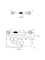
- FIG. 3 illustrates an embodiment, where a distributed generator 10 is connected to a utility grid 11. Between the generator 10 and the grid 11 is an impedance 12. The generator controls a current i DG at a grid connection point.
- ip DG ( t ) is the active current delivered by generator at a time instant t
- ip DG (t - 1) is the active current delivered by the generator at the time instant t - 1
- ⁇ ip DG ( t ) is the current variations between time instant t - 1 and t. Similar notations apply also to a reactive current
- Variations in active and reactive currents lead to voltage ⁇ V DG and/or frequency ⁇ ⁇ DG variations at the grid connection point, depending on the type of impedance the grid has.
- the variations may be very small due to voltage and/or frequency controls on the side of the utility grid.
- these variations will increase and, on the basis of the level of increase, islanding occurrence can be assessed.
- An estimate of the grid impedance may be calculated, for instance, by monitoring the changes ⁇ i DG of the generated current vector and changes ⁇ V DG of grid voltage vector:
- V DG ⁇ t - 1 V g ⁇ t - 1 + Z g ⁇ i DG ⁇ t - 1
- V DG t V g t - Z g ⁇ i DG t
- the current variation ⁇ i DG created by the DG leads to voltage variation ⁇ V DG at the distributed generator terminals.
- ⁇ V DG is then compared with a threshold value V trsh and if its value is larger than the threshold, islanding conditions are considered. Since the variations of voltage at DG terminals need to be larger than the threshold voltage, i.e. ⁇ V DG > V trsh , knowing the value of Z g,est , the current variations can be derived with regard to V trsh as: ⁇ ⁇ i DG > V trsh Z g
- FIG 4 illustrates another embodiment, where a value of grid impedance is used to calculate the right variation necessary to be injected to a grid connection point in order to detect islanding.
- a distributed generator 20 is connected to a utility grid 21. Between the generator 20 and the grid 21 is an impedance 22.
- the generator 20 controls a current i DG at a grid connection point 23.
- the embodiment comprises an apparatus 23 for detecting islanding conditions of the distributed generator 23.
- An apparatus 24 controls the generator 20.
- the apparatus 24 comprises an impedance calculation block 241, and an islanding detection block 242 and a generator controller 243.
- the generator controller may, as in the embodiment of Figure 4 , give an output current reference i * to the generator 20.
- the generator 20 then produces the output current on the basis of the reference.
- an estimate Z g,est of a grid impedance is first calculated in the impedance calculation block 241.
- the calculation may be done, for instance, using the algorithm described by equations 3 to 5.
- the estimated impedance Z g,est is then passed to an islanding detection block 242 which adapts an output power variation in such a way that the variations created in the grid are sufficiently high to determine islanding conditions.
- the islanding detection block 242 may, for instance, calculate a value for a variation reference parameter ⁇ P on the basis of the estimated impedance Z g,est .
- the generator controller 243 may then control the output of the distributed generator 23, on the basis of the variation reference ⁇ P , to induce variations in the grid.
- the controller 243 may, for instance, modify the current reference i * to contain a variation ⁇ i DG,ref , which, in turn, induces variation ⁇ i DG in the output current.
- the islanding condition may be assessed.
- the islanding detection block 242 determines the islanding conditions, for instance by monitoring the voltage variations. The amount of increase in the induced variations is compared to a threshold and if it exceeds the threshold value, islanding is assumed.
- the grid response may also be monitored in other quantities, for instance frequency or phase quantities.
- the level of the threshold may also be determined on the basis of the estimated grid impedance, for instance as in equation 6.
- Impedances between grid and distributed generator may be different for different arrangements. However, impedance between a grid and a distributed generator in one arrangement typically stays constant. By observing a steady state grid response in grid-connected mode, the threshold can be lowered closer to the nuisance trip limit, thus permitting to lower the grid variations even more. Another aspect of lowering the threshold is that by lowering the threshold value as close as possible to the limit where nuisance trip in grid-connected mode may happen, a higher sensitivity of the method in the is-landed mode may be achieved.
Landscapes
- Engineering & Computer Science (AREA)
- Power Engineering (AREA)
- Supply And Distribution Of Alternating Current (AREA)
- Control Of Eletrric Generators (AREA)
Abstract
Description
- The invention relates to distributed power generation and particularly to detecting islanding conditions for distributed generators.
- Lately, distributed generation (DG) based on renewable energy resources has shown a significant growth facilitated by policy makers, global concerns about climate change, availability of affordable energy shortage technologies, interest in clean energy production, etc. Energy suppliers using power plants based on fossil fuel (coal, natural gas, etc.) are also investing in an extension of energy generation portfolio by renewable alternatives such as wind turbines and photovoltaic systems.
- However, for connecting such systems to the utility grid, several requirements are to be met. In case of photovoltaic systems (PV), these requirements are typically published by standardizing institutions, such as IEC and IEEE, but also by local regulating authorities. One of the requirements, mandatory in many parts of the world, is that photovoltaic systems should be able to detect islanding conditions.
- Islanding refers to a condition of a distributed generator continuing to power a part of a distribution network even though power from an electric utility is no longer present.
Figures 1a and 1b show a difference between a grid-connected mode and an islanding mode. InFigure 1a , aswitching device 1, e.g. circuit breaker or fuse, is closed, and distributed generators operate in grid-connected mode. InFigure 1b , theswitching device 1 is opened and thelower part 2 of the network is no longer connected to the main grid. However, if the power generated by distributed generators closely matches the power required by the load, the network can continue operation in islanding mode. - Islanding can be dangerous to utility workers, who may not realize that the particular part of the network is still powered even though there is no power from the main grid. Also, islanding can lead to damages to customer equipment, especially in situations of re-closing into an island. For that reason, distributed generators may have to be able to detect islanding and immediately stop power production.
- Historically many methods for detecting islanding conditions have been developed. These methods can be categorized in three main groups: passive, active, and communication-based methods.
- Passive methods monitor one or more grid variables and, based on deviation of the variables from allowed thresholds, a decision of disconnecting (detection of islanding) can be made.
- Active methods deliberately disturb the grid and, on the basis of the grid response to that disturbance (variation of grid electrical quantities), decide whether or not islanding occurred.
- Communication-based methods make use of a communication means with an external unit (owned, for instance, by the distribution system operator) which signalizes the opening of the switching equipment to all distributed generators in that part of the network.
- Each of the above methods has its own strengths and weaknesses. Active methods are the most frequently encountered in today's market. An advantage of the active methods is a very small non-detection zone and ease of implementation in a microprocessor. However, active methods may have a disadvantage due to the disturbances they introduce into the grid, disturbances which very often are associated with power quality. In some cases, large current variations produced for observing the islanding detection may have a negative influence on the power quality.
- The variations may be empirically selected in order to ensure that the distributed generator does not miss islanding conditions. The variation may be chosen to be higher than necessary just to provide a safety margin. The maximum variation may be limited by the regulating authorities.
- While current variations produced by distributed generators are fixed for a certain manufacturer, a grid response to these variations is dependent on the grid impedance seen by the distributed generator. Consequently, the grid response is different for different impedances (or different locations). Therefore, the disturbances created by the active methods may not be optimal for all locations and operating conditions.
- An object of the present invention is to provide a method and an apparatus for implementing the method so as to overcome the above problems. The objects of the invention are achieved by a method and an apparatus which are characterized by what is stated in the independent claims. The preferred embodiments of the invention are disclosed in the dependent claims.
- The invention is based on the idea of adaptive self adjustment of the variations induced to the grid for different values of grid impedances. The variations may be adjusted on the basis of an estimated grid impedance. A threshold value to which a grid response is compared may also be adjusted.
- The disclosed adaptive adjustment for different values of grid impedance can help diminish an impact on power quality caused by potentially large power variations. An impact on other distributed generators connected to the same feeder may also diminish, thus minimizing the risk of exceeding their nuisance trip limits (a limit at which a small disturbance in the network, such as connection/disconnection of a load, causes a fault event on the distributed generator) due to potentially large grid voltage variations.
- In the following the invention will be described in greater detail by means of preferred embodiments with reference to the attached drawings, in which
-
Figures 1a and 1b illustrate a main difference between a grid connected mode and an islanding mode of a distributed network; -
Figure 2 illustrates a relation between voltage, impedance and current; -
Figure 3 illustrates an embodiment, where a distributed generator is connected to a utility grid; and -
Figure 4 illustrates an embodiment, where a value of grid impedance is used to calculate the right variation necessary to be injected to a grid connection point in order to detect islanding. - As an example, a grid response in terms of voltage variations is detailed below.
Figure 2 illustrates a relation between voltage variation ΔVDG , grid impedance Zg and an output current variation ΔiDG . The output current variation ΔiDG of a distributed generator is represented by a solid line. The voltage variation ΔVDG at the output of the distributed generator is represented by a dashed line. - Because of a direct relation between these quantities, two situations can be found where the voltage variation gets a large magnitude. If the current variation ΔiDG is large, the voltage variation ΔVDG is large. Similarly, if grid impedance Zg is large, the voltage variation ΔVDG is large.
- If grid impedance Zg is known, one can control the current variation ΔiDG in such a way that a voltage drop over that impedance Zg is constant and controllable over time. A controlled voltage variation ΔVDG,ctrd is represented a dotted line in
Figure 2 . The voltage variation can be controlled to be as large as necessary above the threshold but not too large. - Therefore, a following method for detecting islanding conditions may be used. First, grid impedance is estimated. To achieve this, monitoring of grid parameters such as voltage, frequency or current may be necessary. A variation may then be induced on a first electrical quantity of the grid. In order to minimize an impact of the induced variance on the grid, a magnitude of the induced variation may be optimized on the grid on the basis of the estimated grid impedance. The first electrical quantity may, for instance, be the output current of the distributed generator. The variation may, for instance, be induced by determining a variation reference on the basis of the estimated impedance, and by controlling the distributed generator, on the basis of the variation reference, to induce the variation on the first electrical quantity.
- As the variations of the first electrical quantity cause variations to a second electrical quantity of the grid, a grid response, in a form of the variations of the second electrical quantity, may then be monitored. The islanding conditions may be determined on the basis of the monitored response. The second electrical quantity may, for instance, be a voltage, frequency or phase of the grid at a connection point of the distributed generator. The variation of a second electrical quantity is determined to estimate the grid impedance.
- Then, the variation of the second electrical quantity may be compared with a set threshold. The islanding conditions may then be determined on the basis of the comparison. The threshold does not have to be fixed. A level for the threshold may, for instance, be determined on the basis of a steady state grid response in grid-connected mode.
-
Figure 3 illustrates an embodiment, where a distributedgenerator 10 is connected to autility grid 11. Between thegenerator 10 and thegrid 11 is animpedance 12. The generator controls a current iDG at a grid connection point. An active component and a reactive component of the current iDG may be represented as follows:

where ipDG (t) is the active current delivered by generator at a time instant t, ipDG(t - 1) is the active current delivered by the generator at the time instant t - 1 and ΔipDG (t) is the current variations between time instant t - 1 and t. Similar notations apply also to a reactive current iqDG. - Variations in active and reactive currents lead to voltage ΔVDG and/or frequency ΔƒDG variations at the grid connection point, depending on the type of impedance the grid has. In case the utility grid is present (grid-connected mode), the variations may be very small due to voltage and/or frequency controls on the side of the utility grid. However, in a situation that the grid source is disconnected (islanding mode), these variations will increase and, on the basis of the level of increase, islanding occurrence can be assessed.
- The method of the disclosure may be used in the embodiment of
Figure 3 . An estimate of the grid impedance may be calculated, for instance, by monitoring the changes ΔiDG of the generated current vector and changes ΔVDG of grid voltage vector:

- Assuming that the grid voltage Vg does not change significantly, an estimate Zg,est of the grid impedance may be calculated as follows:

- The current variation ΔiDG created by the DG leads to voltage variation ΔVDG at the distributed generator terminals. ΔVDG is then compared with a threshold value Vtrsh and if its value is larger than the threshold, islanding conditions are considered. Since the variations of voltage at DG terminals need to be larger than the threshold voltage, i.e. ΔVDG > Vtrsh, knowing the value of Zg,est , the current variations can be derived with regard to Vtrsh as:

-
Figure 4 illustrates another embodiment, where a value of grid impedance is used to calculate the right variation necessary to be injected to a grid connection point in order to detect islanding. A distributedgenerator 20 is connected to autility grid 21. Between thegenerator 20 and thegrid 21 is animpedance 22. Thegenerator 20 controls a current iDG at agrid connection point 23. The embodiment comprises anapparatus 23 for detecting islanding conditions of the distributedgenerator 23. Anapparatus 24 controls thegenerator 20. Theapparatus 24 comprises animpedance calculation block 241, and anislanding detection block 242 and agenerator controller 243. The generator controller may, as in the embodiment ofFigure 4 , give an output current reference i* to thegenerator 20. Thegenerator 20 then produces the output current on the basis of the reference. - On the basis of a voltage measurement at a point of
connection 23 with the utility grid, an estimate Zg,est of a grid impedance is first calculated in theimpedance calculation block 241. The calculation may be done, for instance, using the algorithm described by equations 3 to 5. - The estimated impedance Zg,est is then passed to an
islanding detection block 242 which adapts an output power variation in such a way that the variations created in the grid are sufficiently high to determine islanding conditions. Theislanding detection block 242 may, for instance, calculate a value for a variation reference parameter ΔP on the basis of the estimated impedance Zg,est . Thegenerator controller 243 may then control the output of the distributedgenerator 23, on the basis of the variation reference ΔP, to induce variations in the grid. Thecontroller 243 may, for instance, modify the current reference i* to contain a variation ΔiDG,ref, which, in turn, induces variation ΔiDG in the output current. - On the basis of the grid response to the variations, the islanding condition may be assessed. The
islanding detection block 242 determines the islanding conditions, for instance by monitoring the voltage variations. The amount of increase in the induced variations is compared to a threshold and if it exceeds the threshold value, islanding is assumed. The grid response may also be monitored in other quantities, for instance frequency or phase quantities. - If islanding condition is assumed, a decision of disconnecting the distributed
generator 23 from the grid may be made. The level of the threshold may also be determined on the basis of the estimated grid impedance, for instance as in equation 6. - Impedances between grid and distributed generator may be different for different arrangements. However, impedance between a grid and a distributed generator in one arrangement typically stays constant. By observing a steady state grid response in grid-connected mode, the threshold can be lowered closer to the nuisance trip limit, thus permitting to lower the grid variations even more. Another aspect of lowering the threshold is that by lowering the threshold value as close as possible to the limit where nuisance trip in grid-connected mode may happen, a higher sensitivity of the method in the is-landed mode may be achieved.
- It will be obvious to a person skilled in the art that, as the technology advances, the inventive concept can be implemented in various ways. The invention and its embodiments are not limited to the examples described above but may vary within the scope of the claims.
Claims (5)
- A method for detecting islanding conditions for a distributed generator connected to a grid, wherein the method comprises steps of:estimating a grid impedance,inducing a variation on a value of a first electrical quantity of the grid, wherein a magnitude of the induced variation is optimized on the basis of the estimated grid impedance in order to minimize an impact of the induced variation on the grid,monitoring a grid response to the variation, anddetermining islanding conditions on the basis of the monitored response.
- A method according to claim 1, wherein inducing a variation on the grid comprises
determining a variation reference on the basis of the estimated impedance,
controlling the distributed generator, on the basis of the variations reference, to induce a variation on the first electrical quantity. - A method according to claim 1 or 2, wherein monitoring the grid response comprises
determining a variation in a second electrical quantity of the grid, such as voltage, frequency or phase, induced by the variations of the first electrical quantity,
comparing the variation in the second electrical quantity with a set threshold, and
making a decision of disconnecting the generator on the basis of the comparison. - A method according to any one of claims 1 to 3, wherein comparing the determined quantity with the set threshold comprises
determining a level for the threshold on the basis of a steady grid response in grid connected mode. - An apparatus for detecting islanding conditions of a distributed generator connected to a grid, wherein the apparatus comprises:means for estimating a grid impedance,means for inducing a variation on a value of a first electrical quantity of the grid, wherein a magnitude of the induced variation is optimized on the basis of the estimated grid impedance in order to minimize an impact of the induced variation on the grid,means for monitoring a grid response to the variation, andmeans for determining islanding conditions on the basis of the monitored response.
Priority Applications (3)
| Application Number | Priority Date | Filing Date | Title |
|---|---|---|---|
| EP11158034.6A EP2501014B1 (en) | 2011-03-14 | 2011-03-14 | Method and apparatus for detecting islanding conditions of distributed generator |
| CN201210063665.8A CN102684219B (en) | 2011-03-14 | 2012-03-12 | Method and apparatus for detecting islanding conditions of distributed generator |
| US13/419,645 US20120239215A1 (en) | 2011-03-14 | 2012-03-14 | Method and apparatus for detecting islanding conditions of distributed generator |
Applications Claiming Priority (1)
| Application Number | Priority Date | Filing Date | Title |
|---|---|---|---|
| EP11158034.6A EP2501014B1 (en) | 2011-03-14 | 2011-03-14 | Method and apparatus for detecting islanding conditions of distributed generator |
Publications (3)
| Publication Number | Publication Date |
|---|---|
| EP2501014A1 EP2501014A1 (en) | 2012-09-19 |
| EP2501014A9 true EP2501014A9 (en) | 2013-01-16 |
| EP2501014B1 EP2501014B1 (en) | 2016-05-11 |
Family
ID=44597255
Family Applications (1)
| Application Number | Title | Priority Date | Filing Date |
|---|---|---|---|
| EP11158034.6A Active EP2501014B1 (en) | 2011-03-14 | 2011-03-14 | Method and apparatus for detecting islanding conditions of distributed generator |
Country Status (3)
| Country | Link |
|---|---|
| US (1) | US20120239215A1 (en) |
| EP (1) | EP2501014B1 (en) |
| CN (1) | CN102684219B (en) |
Families Citing this family (14)
| Publication number | Priority date | Publication date | Assignee | Title |
|---|---|---|---|---|
| CN102904225B (en) * | 2012-10-08 | 2014-11-12 | 华南理工大学 | Pilot protection method for distribution network with distributed power supply |
| US10289080B2 (en) | 2012-10-11 | 2019-05-14 | Flexgen Power Systems, Inc. | Multi-generator applications using variable speed and solid state generators for efficiency and frequency stabilization |
| US9312699B2 (en) | 2012-10-11 | 2016-04-12 | Flexgen Power Systems, Inc. | Island grid power supply apparatus and methods using energy storage for transient stabilization |
| US9553517B2 (en) | 2013-03-01 | 2017-01-24 | Fllexgen Power Systems, Inc. | Hybrid energy storage system and methods |
| DE102013111870A1 (en) * | 2013-10-28 | 2015-04-30 | Sma Solar Technology Ag | Inverter and detection method for an inverter for detecting a network fault |
| CN103795090B (en) * | 2014-01-29 | 2016-02-24 | 广东电网公司电力科学研究院 | Based on the emergency control method that the generator reactive of WAMS is exerted oneself |
| US10574055B2 (en) | 2014-12-30 | 2020-02-25 | Flexgen Power Systems, Inc. | Transient power stabilization device with active and reactive power control |
| US10673239B2 (en) * | 2015-09-18 | 2020-06-02 | Abb Power Grids Switzerland Ag | Micro-grid having a diesel generator with clutch |
| US10892638B2 (en) | 2017-08-03 | 2021-01-12 | Heila Technologies, Inc. | Automatic detection of distributed energy resources system parameters |
| CA3071845A1 (en) | 2017-08-03 | 2019-02-07 | Heila Technologies, Inc. | Grid asset manager |
| CN109031045B (en) * | 2018-08-21 | 2020-09-29 | 东北大学 | Active power-voltage cross correlation degree island detection method based on self-adaptive threshold selection |
| US10971931B2 (en) | 2018-11-13 | 2021-04-06 | Heila Technologies, Inc. | Decentralized hardware-in-the-loop scheme |
| EP3996231B1 (en) * | 2020-11-10 | 2023-10-11 | Rolls-Royce Solutions GmbH | Method and apparatus for detecting of an islanding of a distributed electrical power system |
| CN113346477B (en) * | 2021-05-08 | 2023-09-19 | 深圳市禾望电气股份有限公司 | Power grid parameter estimation method and system |
Family Cites Families (9)
| Publication number | Priority date | Publication date | Assignee | Title |
|---|---|---|---|---|
| US6429546B1 (en) * | 1998-11-20 | 2002-08-06 | Georgia Tech Research Corporation | Systems and methods for preventing islanding of grid-connected electrical power systems |
| US6603290B2 (en) * | 2001-11-26 | 2003-08-05 | Visteon Global Technologies, Inc. | Anti-islanding detection scheme for distributed power generation |
| US7016793B2 (en) * | 2003-10-01 | 2006-03-21 | General Electric Company | Method and apparatus for anti-islanding protection of distributed generations |
| US7427815B1 (en) * | 2003-11-14 | 2008-09-23 | General Electric Company | Method, memory media and apparatus for detection of grid disconnect |
| US7408268B1 (en) * | 2005-08-04 | 2008-08-05 | Magnetek, S.P.A. | Anti-islanding method and system for distributed power generation systems |
| EP1764894A1 (en) * | 2005-09-19 | 2007-03-21 | ABB Schweiz AG | Method for detecting islanding operation of a distributed generator |
| US8334618B2 (en) * | 2009-11-13 | 2012-12-18 | Eaton Corporation | Method and area electric power system detecting islanding by employing controlled reactive power injection by a number of inverters |
| JP5605548B2 (en) * | 2010-04-12 | 2014-10-15 | 富士電機株式会社 | Grid interconnection device |
| KR101120367B1 (en) * | 2010-06-22 | 2012-03-02 | 성균관대학교산학협력단 | Apparatus and method for anti-islanding of power conditioning system |
-
2011
- 2011-03-14 EP EP11158034.6A patent/EP2501014B1/en active Active
-
2012
- 2012-03-12 CN CN201210063665.8A patent/CN102684219B/en active Active
- 2012-03-14 US US13/419,645 patent/US20120239215A1/en not_active Abandoned
Also Published As
| Publication number | Publication date |
|---|---|
| EP2501014A1 (en) | 2012-09-19 |
| CN102684219B (en) | 2015-07-01 |
| EP2501014B1 (en) | 2016-05-11 |
| US20120239215A1 (en) | 2012-09-20 |
| CN102684219A (en) | 2012-09-19 |
Similar Documents
| Publication | Publication Date | Title |
|---|---|---|
| EP2501014B1 (en) | Method and apparatus for detecting islanding conditions of distributed generator | |
| Zamani et al. | A novel hybrid islanding detection method using dynamic characteristics of synchronous generator and signal processing technique | |
| US8497599B2 (en) | Electrical generator network and a local electrical system | |
| US9170306B2 (en) | Islanding detection method and system | |
| TWI568123B (en) | Method and device for feeding electrical energy into an electrical supply grid | |
| US9494637B2 (en) | Method for detecting islanding operation of distributed power generator | |
| EP2590291B1 (en) | Method and apparatus for detecting islanding conditions of a distributed grid | |
| US9494635B2 (en) | Islanding detection in electricity distribution network | |
| WO2013142553A2 (en) | System and method for islanding detection and protection | |
| EP2645517A1 (en) | Improvement for islanding detection reliability in electricity distribution network | |
| US20150333503A1 (en) | Centralized dc curtailment for overvoltage protection | |
| Maki et al. | Problems related to islanding protection of distributed generation in distribution network | |
| US10024920B2 (en) | Systems and methods for swing angle estimation in an electrical power system | |
| EP2858201A1 (en) | Detection of islanding condition in electricity network | |
| Raju et al. | Evaluation of Passive Islanding Detection Methods for Line to Ground Unsymmetrical Fault in Three Phase Microgrid Systems: Microgrid Islanding Detection Method | |
| CN210629117U (en) | Wind turbine generator system island cutting device with high voltage ride through function | |
| Alhadrawi et al. | Review of microgrid protection strategies: current status and future prospects | |
| CA3060181C (en) | Method for detecting formation of a separate system | |
| Hairi et al. | Sensitivity and stability analysis of loss of main protection in active distribution networks | |
| Lukač et al. | Anti-islanding protection of distributed generators with regard to sensitivity in a balance and power system stability | |
| CN110768297A (en) | Wind turbine generator set island switching-out method and device with high voltage ride through function | |
| CN104267317B (en) | Islanding detection method based on reactance layered switching | |
| KR101682561B1 (en) | Method and system for controlling low-voltage ride through of a wind farm | |
| Pradhan et al. | Performance of Distance Relaying Scheme under High Penetration of RES | |
| Patil et al. | A novel method for islanding detection of distribution system with distributed generator |
Legal Events
| Date | Code | Title | Description |
|---|---|---|---|
| PUAI | Public reference made under article 153(3) epc to a published international application that has entered the european phase |
Free format text: ORIGINAL CODE: 0009012 |
|
| AK | Designated contracting states |
Kind code of ref document: A1 Designated state(s): AL AT BE BG CH CY CZ DE DK EE ES FI FR GB GR HR HU IE IS IT LI LT LU LV MC MK MT NL NO PL PT RO RS SE SI SK SM TR |
|
| AX | Request for extension of the european patent |
Extension state: BA ME |
|
| 17P | Request for examination filed |
Effective date: 20121227 |
|
| 17Q | First examination report despatched |
Effective date: 20150528 |
|
| GRAP | Despatch of communication of intention to grant a patent |
Free format text: ORIGINAL CODE: EPIDOSNIGR1 |
|
| INTG | Intention to grant announced |
Effective date: 20151103 |
|
| GRAS | Grant fee paid |
Free format text: ORIGINAL CODE: EPIDOSNIGR3 |
|
| GRAA | (expected) grant |
Free format text: ORIGINAL CODE: 0009210 |
|
| AK | Designated contracting states |
Kind code of ref document: B1 Designated state(s): AL AT BE BG CH CY CZ DE DK EE ES FI FR GB GR HR HU IE IS IT LI LT LU LV MC MK MT NL NO PL PT RO RS SE SI SK SM TR |
|
| REG | Reference to a national code |
Ref country code: GB Ref legal event code: FG4D |
|
| REG | Reference to a national code |
Ref country code: CH Ref legal event code: EP |
|
| REG | Reference to a national code |
Ref country code: AT Ref legal event code: REF Ref document number: 799347 Country of ref document: AT Kind code of ref document: T Effective date: 20160515 |
|
| REG | Reference to a national code |
Ref country code: IE Ref legal event code: FG4D |
|
| REG | Reference to a national code |
Ref country code: DE Ref legal event code: R096 Ref document number: 602011026327 Country of ref document: DE |
|
| REG | Reference to a national code |
Ref country code: LT Ref legal event code: MG4D |
|
| REG | Reference to a national code |
Ref country code: NL Ref legal event code: MP Effective date: 20160511 |
|
| PG25 | Lapsed in a contracting state [announced via postgrant information from national office to epo] |
Ref country code: LT Free format text: LAPSE BECAUSE OF FAILURE TO SUBMIT A TRANSLATION OF THE DESCRIPTION OR TO PAY THE FEE WITHIN THE PRESCRIBED TIME-LIMIT Effective date: 20160511 Ref country code: NL Free format text: LAPSE BECAUSE OF FAILURE TO SUBMIT A TRANSLATION OF THE DESCRIPTION OR TO PAY THE FEE WITHIN THE PRESCRIBED TIME-LIMIT Effective date: 20160511 Ref country code: FI Free format text: LAPSE BECAUSE OF FAILURE TO SUBMIT A TRANSLATION OF THE DESCRIPTION OR TO PAY THE FEE WITHIN THE PRESCRIBED TIME-LIMIT Effective date: 20160511 Ref country code: NO Free format text: LAPSE BECAUSE OF FAILURE TO SUBMIT A TRANSLATION OF THE DESCRIPTION OR TO PAY THE FEE WITHIN THE PRESCRIBED TIME-LIMIT Effective date: 20160811 |
|
| REG | Reference to a national code |
Ref country code: AT Ref legal event code: MK05 Ref document number: 799347 Country of ref document: AT Kind code of ref document: T Effective date: 20160511 |
|
| PG25 | Lapsed in a contracting state [announced via postgrant information from national office to epo] |
Ref country code: HR Free format text: LAPSE BECAUSE OF FAILURE TO SUBMIT A TRANSLATION OF THE DESCRIPTION OR TO PAY THE FEE WITHIN THE PRESCRIBED TIME-LIMIT Effective date: 20160511 Ref country code: GR Free format text: LAPSE BECAUSE OF FAILURE TO SUBMIT A TRANSLATION OF THE DESCRIPTION OR TO PAY THE FEE WITHIN THE PRESCRIBED TIME-LIMIT Effective date: 20160812 Ref country code: ES Free format text: LAPSE BECAUSE OF FAILURE TO SUBMIT A TRANSLATION OF THE DESCRIPTION OR TO PAY THE FEE WITHIN THE PRESCRIBED TIME-LIMIT Effective date: 20160511 Ref country code: LV Free format text: LAPSE BECAUSE OF FAILURE TO SUBMIT A TRANSLATION OF THE DESCRIPTION OR TO PAY THE FEE WITHIN THE PRESCRIBED TIME-LIMIT Effective date: 20160511 Ref country code: PT Free format text: LAPSE BECAUSE OF FAILURE TO SUBMIT A TRANSLATION OF THE DESCRIPTION OR TO PAY THE FEE WITHIN THE PRESCRIBED TIME-LIMIT Effective date: 20160912 Ref country code: SE Free format text: LAPSE BECAUSE OF FAILURE TO SUBMIT A TRANSLATION OF THE DESCRIPTION OR TO PAY THE FEE WITHIN THE PRESCRIBED TIME-LIMIT Effective date: 20160511 Ref country code: RS Free format text: LAPSE BECAUSE OF FAILURE TO SUBMIT A TRANSLATION OF THE DESCRIPTION OR TO PAY THE FEE WITHIN THE PRESCRIBED TIME-LIMIT Effective date: 20160511 |
|
| PG25 | Lapsed in a contracting state [announced via postgrant information from national office to epo] |
Ref country code: EE Free format text: LAPSE BECAUSE OF FAILURE TO SUBMIT A TRANSLATION OF THE DESCRIPTION OR TO PAY THE FEE WITHIN THE PRESCRIBED TIME-LIMIT Effective date: 20160511 Ref country code: RO Free format text: LAPSE BECAUSE OF FAILURE TO SUBMIT A TRANSLATION OF THE DESCRIPTION OR TO PAY THE FEE WITHIN THE PRESCRIBED TIME-LIMIT Effective date: 20160511 Ref country code: SK Free format text: LAPSE BECAUSE OF FAILURE TO SUBMIT A TRANSLATION OF THE DESCRIPTION OR TO PAY THE FEE WITHIN THE PRESCRIBED TIME-LIMIT Effective date: 20160511 Ref country code: CZ Free format text: LAPSE BECAUSE OF FAILURE TO SUBMIT A TRANSLATION OF THE DESCRIPTION OR TO PAY THE FEE WITHIN THE PRESCRIBED TIME-LIMIT Effective date: 20160511 Ref country code: DK Free format text: LAPSE BECAUSE OF FAILURE TO SUBMIT A TRANSLATION OF THE DESCRIPTION OR TO PAY THE FEE WITHIN THE PRESCRIBED TIME-LIMIT Effective date: 20160511 |
|
| REG | Reference to a national code |
Ref country code: DE Ref legal event code: R097 Ref document number: 602011026327 Country of ref document: DE |
|
| PG25 | Lapsed in a contracting state [announced via postgrant information from national office to epo] |
Ref country code: PL Free format text: LAPSE BECAUSE OF FAILURE TO SUBMIT A TRANSLATION OF THE DESCRIPTION OR TO PAY THE FEE WITHIN THE PRESCRIBED TIME-LIMIT Effective date: 20160511 Ref country code: SM Free format text: LAPSE BECAUSE OF FAILURE TO SUBMIT A TRANSLATION OF THE DESCRIPTION OR TO PAY THE FEE WITHIN THE PRESCRIBED TIME-LIMIT Effective date: 20160511 Ref country code: AT Free format text: LAPSE BECAUSE OF FAILURE TO SUBMIT A TRANSLATION OF THE DESCRIPTION OR TO PAY THE FEE WITHIN THE PRESCRIBED TIME-LIMIT Effective date: 20160511 Ref country code: BE Free format text: LAPSE BECAUSE OF FAILURE TO SUBMIT A TRANSLATION OF THE DESCRIPTION OR TO PAY THE FEE WITHIN THE PRESCRIBED TIME-LIMIT Effective date: 20160511 |
|
| PLBE | No opposition filed within time limit |
Free format text: ORIGINAL CODE: 0009261 |
|
| STAA | Information on the status of an ep patent application or granted ep patent |
Free format text: STATUS: NO OPPOSITION FILED WITHIN TIME LIMIT |
|
| REG | Reference to a national code |
Ref country code: FR Ref legal event code: PLFP Year of fee payment: 7 |
|
| 26N | No opposition filed |
Effective date: 20170214 |
|
| PG25 | Lapsed in a contracting state [announced via postgrant information from national office to epo] |
Ref country code: SI Free format text: LAPSE BECAUSE OF FAILURE TO SUBMIT A TRANSLATION OF THE DESCRIPTION OR TO PAY THE FEE WITHIN THE PRESCRIBED TIME-LIMIT Effective date: 20160511 |
|
| PG25 | Lapsed in a contracting state [announced via postgrant information from national office to epo] |
Ref country code: MC Free format text: LAPSE BECAUSE OF FAILURE TO SUBMIT A TRANSLATION OF THE DESCRIPTION OR TO PAY THE FEE WITHIN THE PRESCRIBED TIME-LIMIT Effective date: 20160511 |
|
| REG | Reference to a national code |
Ref country code: IE Ref legal event code: MM4A |
|
| PG25 | Lapsed in a contracting state [announced via postgrant information from national office to epo] |
Ref country code: LU Free format text: LAPSE BECAUSE OF NON-PAYMENT OF DUE FEES Effective date: 20170314 |
|
| PG25 | Lapsed in a contracting state [announced via postgrant information from national office to epo] |
Ref country code: IE Free format text: LAPSE BECAUSE OF NON-PAYMENT OF DUE FEES Effective date: 20170314 |
|
| REG | Reference to a national code |
Ref country code: FR Ref legal event code: PLFP Year of fee payment: 8 |
|
| PG25 | Lapsed in a contracting state [announced via postgrant information from national office to epo] |
Ref country code: MT Free format text: LAPSE BECAUSE OF NON-PAYMENT OF DUE FEES Effective date: 20170314 |
|
| PG25 | Lapsed in a contracting state [announced via postgrant information from national office to epo] |
Ref country code: AL Free format text: LAPSE BECAUSE OF FAILURE TO SUBMIT A TRANSLATION OF THE DESCRIPTION OR TO PAY THE FEE WITHIN THE PRESCRIBED TIME-LIMIT Effective date: 20160511 |
|
| PG25 | Lapsed in a contracting state [announced via postgrant information from national office to epo] |
Ref country code: HU Free format text: LAPSE BECAUSE OF FAILURE TO SUBMIT A TRANSLATION OF THE DESCRIPTION OR TO PAY THE FEE WITHIN THE PRESCRIBED TIME-LIMIT; INVALID AB INITIO Effective date: 20110314 |
|
| PG25 | Lapsed in a contracting state [announced via postgrant information from national office to epo] |
Ref country code: BG Free format text: LAPSE BECAUSE OF FAILURE TO SUBMIT A TRANSLATION OF THE DESCRIPTION OR TO PAY THE FEE WITHIN THE PRESCRIBED TIME-LIMIT Effective date: 20160511 |
|
| REG | Reference to a national code |
Ref country code: CH Ref legal event code: PFUS Owner name: ABB SCHWEIZ AG, CH Free format text: FORMER OWNER: ABB RESEARCH LTD., CH |
|
| PG25 | Lapsed in a contracting state [announced via postgrant information from national office to epo] |
Ref country code: CY Free format text: LAPSE BECAUSE OF NON-PAYMENT OF DUE FEES Effective date: 20160511 |
|
| REG | Reference to a national code |
Ref country code: DE Ref legal event code: R081 Ref document number: 602011026327 Country of ref document: DE Owner name: ABB SCHWEIZ AG, CH Free format text: FORMER OWNER: ABB RESEARCH LTD., ZUERICH, CH |
|
| PG25 | Lapsed in a contracting state [announced via postgrant information from national office to epo] |
Ref country code: MK Free format text: LAPSE BECAUSE OF FAILURE TO SUBMIT A TRANSLATION OF THE DESCRIPTION OR TO PAY THE FEE WITHIN THE PRESCRIBED TIME-LIMIT Effective date: 20160511 |
|
| REG | Reference to a national code |
Ref country code: GB Ref legal event code: 732E Free format text: REGISTERED BETWEEN 20200206 AND 20200212 |
|
| PG25 | Lapsed in a contracting state [announced via postgrant information from national office to epo] |
Ref country code: TR Free format text: LAPSE BECAUSE OF FAILURE TO SUBMIT A TRANSLATION OF THE DESCRIPTION OR TO PAY THE FEE WITHIN THE PRESCRIBED TIME-LIMIT Effective date: 20160511 |
|
| PG25 | Lapsed in a contracting state [announced via postgrant information from national office to epo] |
Ref country code: IS Free format text: LAPSE BECAUSE OF FAILURE TO SUBMIT A TRANSLATION OF THE DESCRIPTION OR TO PAY THE FEE WITHIN THE PRESCRIBED TIME-LIMIT Effective date: 20160911 |
|
| PGFP | Annual fee paid to national office [announced via postgrant information from national office to epo] |
Ref country code: FR Payment date: 20230324 Year of fee payment: 13 |
|
| PGFP | Annual fee paid to national office [announced via postgrant information from national office to epo] |
Ref country code: IT Payment date: 20230328 Year of fee payment: 13 Ref country code: CH Payment date: 20230402 Year of fee payment: 13 |
|
| PGFP | Annual fee paid to national office [announced via postgrant information from national office to epo] |
Ref country code: DE Payment date: 20240320 Year of fee payment: 14 Ref country code: GB Payment date: 20240320 Year of fee payment: 14 |