US10024920B2 - Systems and methods for swing angle estimation in an electrical power system - Google Patents
Systems and methods for swing angle estimation in an electrical power system Download PDFInfo
- Publication number
- US10024920B2 US10024920B2 US13/968,684 US201313968684A US10024920B2 US 10024920 B2 US10024920 B2 US 10024920B2 US 201313968684 A US201313968684 A US 201313968684A US 10024920 B2 US10024920 B2 US 10024920B2
- Authority
- US
- United States
- Prior art keywords
- power
- swing
- module
- end generator
- source
- Prior art date
- Legal status (The legal status is an assumption and is not a legal conclusion. Google has not performed a legal analysis and makes no representation as to the accuracy of the status listed.)
- Active, expires
Links
- 238000000034 method Methods 0.000 title claims abstract description 46
- 238000001514 detection method Methods 0.000 claims abstract description 90
- 230000008859 change Effects 0.000 claims description 19
- 230000009849 deactivation Effects 0.000 claims description 10
- 238000013459 approach Methods 0.000 description 16
- 238000005259 measurement Methods 0.000 description 11
- 238000012986 modification Methods 0.000 description 11
- 230000004048 modification Effects 0.000 description 11
- 238000004891 communication Methods 0.000 description 10
- 238000012545 processing Methods 0.000 description 10
- 230000005540 biological transmission Effects 0.000 description 6
- 230000009471 action Effects 0.000 description 4
- 230000008569 process Effects 0.000 description 3
- 238000010586 diagram Methods 0.000 description 2
- 238000000926 separation method Methods 0.000 description 2
- 230000001960 triggered effect Effects 0.000 description 2
- 238000003491 array Methods 0.000 description 1
- 238000000429 assembly Methods 0.000 description 1
- 230000000712 assembly Effects 0.000 description 1
- 230000000694 effects Effects 0.000 description 1
- 239000000835 fiber Substances 0.000 description 1
- 239000000463 material Substances 0.000 description 1
- 230000007935 neutral effect Effects 0.000 description 1
- 239000013307 optical fiber Substances 0.000 description 1
- 230000010355 oscillation Effects 0.000 description 1
- 230000003068 static effect Effects 0.000 description 1
- 230000001360 synchronised effect Effects 0.000 description 1
Images


Classifications
-
- H—ELECTRICITY
- H02—GENERATION; CONVERSION OR DISTRIBUTION OF ELECTRIC POWER
- H02J—CIRCUIT ARRANGEMENTS OR SYSTEMS FOR SUPPLYING OR DISTRIBUTING ELECTRIC POWER; SYSTEMS FOR STORING ELECTRIC ENERGY
- H02J3/00—Circuit arrangements for ac mains or ac distribution networks
- H02J3/24—Arrangements for preventing or reducing oscillations of power in networks
- H02J3/242—Arrangements for preventing or reducing oscillations of power in networks using phasor measuring units [PMU]
-
- G—PHYSICS
- G01—MEASURING; TESTING
- G01R—MEASURING ELECTRIC VARIABLES; MEASURING MAGNETIC VARIABLES
- G01R31/00—Arrangements for testing electric properties; Arrangements for locating electric faults; Arrangements for electrical testing characterised by what is being tested not provided for elsewhere
- G01R31/34—Testing dynamo-electric machines
- G01R31/343—Testing dynamo-electric machines in operation
-
- G—PHYSICS
- G01—MEASURING; TESTING
- G01R—MEASURING ELECTRIC VARIABLES; MEASURING MAGNETIC VARIABLES
- G01R19/00—Arrangements for measuring currents or voltages or for indicating presence or sign thereof
- G01R19/25—Arrangements for measuring currents or voltages or for indicating presence or sign thereof using digital measurement techniques
- G01R19/2513—Arrangements for monitoring electric power systems, e.g. power lines or loads; Logging
-
- G—PHYSICS
- G01—MEASURING; TESTING
- G01R—MEASURING ELECTRIC VARIABLES; MEASURING MAGNETIC VARIABLES
- G01R21/00—Arrangements for measuring electric power or power factor
- G01R21/133—Arrangements for measuring electric power or power factor by using digital technique
- G01R21/1331—Measuring real or reactive component, measuring apparent energy
-
- H—ELECTRICITY
- H02—GENERATION; CONVERSION OR DISTRIBUTION OF ELECTRIC POWER
- H02H—EMERGENCY PROTECTIVE CIRCUIT ARRANGEMENTS
- H02H3/00—Emergency protective circuit arrangements for automatic disconnection directly responsive to an undesired change from normal electric working condition with or without subsequent reconnection ; integrated protection
- H02H3/38—Emergency protective circuit arrangements for automatic disconnection directly responsive to an undesired change from normal electric working condition with or without subsequent reconnection ; integrated protection responsive to both voltage and current; responsive to phase angle between voltage and current
- H02H3/382—Emergency protective circuit arrangements for automatic disconnection directly responsive to an undesired change from normal electric working condition with or without subsequent reconnection ; integrated protection responsive to both voltage and current; responsive to phase angle between voltage and current involving phase comparison between current and voltage or between values derived from current and voltage
-
- H—ELECTRICITY
- H02—GENERATION; CONVERSION OR DISTRIBUTION OF ELECTRIC POWER
- H02J—CIRCUIT ARRANGEMENTS OR SYSTEMS FOR SUPPLYING OR DISTRIBUTING ELECTRIC POWER; SYSTEMS FOR STORING ELECTRIC ENERGY
- H02J3/00—Circuit arrangements for ac mains or ac distribution networks
- H02J3/24—Arrangements for preventing or reducing oscillations of power in networks
-
- Y—GENERAL TAGGING OF NEW TECHNOLOGICAL DEVELOPMENTS; GENERAL TAGGING OF CROSS-SECTIONAL TECHNOLOGIES SPANNING OVER SEVERAL SECTIONS OF THE IPC; TECHNICAL SUBJECTS COVERED BY FORMER USPC CROSS-REFERENCE ART COLLECTIONS [XRACs] AND DIGESTS
- Y02—TECHNOLOGIES OR APPLICATIONS FOR MITIGATION OR ADAPTATION AGAINST CLIMATE CHANGE
- Y02E—REDUCTION OF GREENHOUSE GAS [GHG] EMISSIONS, RELATED TO ENERGY GENERATION, TRANSMISSION OR DISTRIBUTION
- Y02E40/00—Technologies for an efficient electrical power generation, transmission or distribution
- Y02E40/70—Smart grids as climate change mitigation technology in the energy generation sector
-
- Y—GENERAL TAGGING OF NEW TECHNOLOGICAL DEVELOPMENTS; GENERAL TAGGING OF CROSS-SECTIONAL TECHNOLOGIES SPANNING OVER SEVERAL SECTIONS OF THE IPC; TECHNICAL SUBJECTS COVERED BY FORMER USPC CROSS-REFERENCE ART COLLECTIONS [XRACs] AND DIGESTS
- Y04—INFORMATION OR COMMUNICATION TECHNOLOGIES HAVING AN IMPACT ON OTHER TECHNOLOGY AREAS
- Y04S—SYSTEMS INTEGRATING TECHNOLOGIES RELATED TO POWER NETWORK OPERATION, COMMUNICATION OR INFORMATION TECHNOLOGIES FOR IMPROVING THE ELECTRICAL POWER GENERATION, TRANSMISSION, DISTRIBUTION, MANAGEMENT OR USAGE, i.e. SMART GRIDS
- Y04S10/00—Systems supporting electrical power generation, transmission or distribution
- Y04S10/22—Flexible AC transmission systems [FACTS] or power factor or reactive power compensating or correcting units
Definitions
- An electrical power system operates under a steady-state condition when there exists a balance between generated and consumed active power for the system.
- Power system disturbances may cause oscillations in machine rotor angles that can result in conditions like a power swing, when internal voltages of system generators slip relative to each other.
- Power system faults, line switching, generator disconnection, or the loss or sudden application of large amounts of load are examples of system disturbances that may cause a power swing event to occur in a power system.
- the system may return to a stable state or experience a large separation of load angle and eventually lose synchronism. Large power swings, stable or unstable, may cause unwanted relay operations at different locations in the system, which can aggravate the system disturbance and can result in major power outages or blackouts.
- asynchronous operation of interconnected generators in the power system as an effect of unstable power swing may initiate uncontrolled tripping of circuit breakers resulting in equipment damage and posing a safety concern for utility operators. Therefore, the asynchronous system areas may need to be separated from each other quickly and dynamically in order to avoid extensive equipment damage and shutdown of major portions of the system. In order to contain these risks, it is required as per international standards to have an optimal generator protection device, such as a generator relay, in place to isolate generators from the rest of the system within a half-slip cycle. The need to meet the international standards challenges protection engineers to ensure selective and reliable relay operation.
- SCV swing center voltage
- a high-speed communication network such as fiber optic or global positioning system (GPS) communication is used to obtain data at a source end from one or more generators at receiving end(s), which is at a remote location from the source end, for SCV estimation.
- GPS global positioning system
- the power swing may be detected by calculating a rate of change of the SCV.
- the time derivative of the SCV is given by below equation:
- a method for detection of power swing for at least a first range of swing angles between an internal voltage (E S ) of a source-end generator and an internal voltage (E R ) of a receiving-end generator includes obtaining a voltage magnitude (V S ) of the source-end generator, and a current magnitude (I S ) of the source-end generator.
- the method further includes estimating a total reactance (X) between the source-end generator and the receiving-end generator, and estimating a first swing angle ( ⁇ ) between the E S and the E R as a function of the obtained V S , the obtained I S and the estimated X.
- the method further includes detecting a power swing condition based on the estimated ⁇ .
- FIG. 1 depicts an electrical power system having multiple generators inter-connected in a mesh arrangement, in accordance with one embodiment.
- FIG. 2 is a block diagram of a power swing detection device, in accordance with one embodiment.
- FIG. 3 represents a two-source system and a vector phasor representation of the two-source system, in accordance with one embodiment of the invention.
- FIG. 4 is a flowchart depicting a method for detection of power swing in the electrical power system, in accordance with one embodiment of the invention.
- FIG. 5 is a flowchart depicting a method for detection of power swing in the electrical power system, in accordance with another embodiment of the invention.
- module may include either a single component or a plurality of components, which are either active, or passive, or both, and are connected or otherwise coupled together to provide the described function.
- Various embodiments of the present invention provide devices and methods to detect a power swing condition (herein referred to as “power swing”) in an electrical power system based on local measurements and one or more system parameters.
- the devices and methods may obtain local measurements including a voltage magnitude (V S ) of a source-end generator in the electrical system and a current magnitude (I S ) of the source-end generator.
- Various embodiments may further estimate one or more system parameters such as a total reactance (X) between the source-end generator and a receiving-end generator in the electrical system, for example.
- a first swing angle ( ⁇ ) between an internal voltage (E S ) of the source-end generator and an internal voltage (E R ) of the receiving-end generator may be estimated as a function of the obtained voltage V S , the obtained current magnitude I S and the estimated total reactance X.
- a power swing condition may be then detected based on the estimated value of ⁇ . In one embodiment, this technique of detecting power swing may be implemented for at least a first range of swing angles between E S and E R , as will be described later. Related systems are also presented.
- a power swing detection device and a related electrical power system is presented.
- FIG. 1 depicts an electrical power system 100 (herein referred to as “system 100 ”) having multiple generators 104 and 108 inter-connected in a mesh arrangement, in accordance with one embodiment of the invention.
- the system 100 may be used for interconnecting alternating current (AC) power grids or microgrids.
- the system 100 may include a source-end 102 and one or more receiving-ends 104 .
- source-end refers to a transmitting end of the system 100 and the term “receiving-end” refers to an end that receives power transmitted from the source-end 102 via a transmission link 106 such as, but not limited to, a transmission cable or a transmission line.
- the source-end 102 includes a generator 108 (herein referred to as a “source-end generator 108 ”) and each receiving-end 104 includes a generator 110 (herein together referred to as “receiving-end generator(s) 110 ”) configured to be electrically coupled to the source-end generator 108 .
- source-end generator 108 the generator 108
- receiving-end generator(s) 110 the generator 110
- power swing may occur between any two generators (for example, between the source-end generator 108 and any of receiving-end generators 110 ) or between two groups of generators.
- FIG. 1 illustrates three receiving-end generators 110 , any number of receiving-end generators may be deployed without deviating from the scope of the invention.
- every source-end generator may include, or be coupled to, a protection unit as described later.
- a power swing is a system phenomenon that is observed when a phase angle (herein referred to as a “swing angle”) of one power source starts to vary in time with respect to another source in the same electrical system network.
- the source-end generator 108 and one of the receiving-end generator 110 may be the two power sources.
- the term “swing angle ( ⁇ )” herein refers to a phase angular separation between an internal voltage (E S ) of the source-end generator 108 and an internal voltage (E R ) of any of the receiving-end generators 110 .
- ⁇ provides information about power swing condition in an electrical power system, in accordance with some embodiments.
- Components illustrated in the system 100 are exemplary and the system 100 may also include various other components (not shown in FIG. 1 ) such as, but not limited to, a turbine connected to the source-end generator 108 , an automatic voltage regulator (AVR), a step-up transformer, a line-side breaker, and one or more electrical loads, for example.
- AVR automatic voltage regulator
- the source-end 102 further includes a voltage transformer 114 for measuring a voltage magnitude (V S ) of the source-end generator 108 , and a current transformer 116 for measuring a current magnitude (I S ) of the source-end generator 108 .
- V S voltage magnitude
- I S current magnitude
- FIG. 1 a single voltage transformer 114 and a single current transformer 116 are shown in FIG. 1 , it will be appreciated by those skilled in the art that any number of current and voltage transformers may be deployed in the system 100 for sensing the local parameters such as I S and V S .
- the term “local measurement” herein refers to a parameter that can be measured within the source-end 102 without the need to communicate with receiving-end generators 110 .
- the system 100 further includes a circuit breaker (CB) 118 at the source-end 102 .
- the circuit breaker 118 is configured to electrically couple/decouple the source-end generator 108 with/from the receiving-end generators 110 .
- the circuit breaker 118 is a 52G generator circuit breaker.
- the circuit breaker 118 may be configured to generate a connection status of the source-end generator 108 .
- connection status refers to a status of the source-end generator 108 that indicates whether it is electrically connected to or disconnected from the rest of the system 100 .
- a high signal (for example, binary 1) may indicate that the circuit breaker 118 is closed and the source-end generator 108 is connected to the system 100
- a low signal (for example, binary 0) may indicate that the circuit breaker 118 is open and the source-end generator 108 is electrically disconnected from the system 100
- the connection status may be determined using other means.
- current feedback such as the presence or absence of a current magnitude I S is used to determine the connection status of the source-end generator 108 .
- a combination of current feedback and circuit breaker position feedback is used to determine the connection status of the source-end generator 108 .
- the circuit breaker 118 , the voltage transformer 114 and the current transformer 116 measure the corresponding data (such as, connection status, Vs, Is, and the like) in real-time.
- the system 100 may also estimate a system parameter such as a total reactance (X) between the source-end generator 108 and any of the receiving-end generators 110 .
- This estimation may be performed in real-time, in accordance with some embodiments.
- real-time may refer to the occurrence of event instantaneously, for example, in the order of milliseconds or microseconds.
- real-time may be near real-time having a predetermined tolerance (for example, two percent) with respect to instantaneous real-time.
- a utility operator or a protection engineer viewing the data may not perceive any delay during display of data.
- the system 100 further includes a power swing detection device 120 (herein referred to as “device 120 ”) at the source-end 102 .
- the term “power swing detection device” as used herein refers to a component that is configured to detect power swing and protect the source-end generator 108 during power swing condition. This protection may be achieved by triggering the circuit breaker 118 to trip or by triggering an alarm, when such a condition is detected. Tripping the circuit breaker 118 may result in the source-end generator 108 being isolated or decoupled from the rest of the system 100 .
- the device 120 may be a protection relay, such as, but not limited to, a digital, numeric, static, or electromechanical protection relay, in accordance with some embodiments.
- the device 120 may include a processing unit 122 and an I/O unit 124 , where the processing unit 122 may analyze data that is received at and transmitted from the I/O unit 124 .
- the processing unit 122 may include, for example, one or more application-specific processors, graphical processing units, digital signal processors, microcomputers, microcontrollers, application specific integrated circuits (ASICs), field programmable gate arrays (FPGAs), or other suitable devices in communication with one or more components of the system 100 .
- the I/O unit 124 may comprise one or more human I/O devices, which enable a utility operator or a protection engineer to communicate with the device 120 or one or more communications devices using any type of communications link.
- the I/O unit 124 interfaces with the voltage transformer 114 , the current transformer 116 , and the circuit breaker 118 to receive local parameters (such as the V S , the I S ) and the connection status, respectively.
- V S and I S may be analog inputs, for example, in the form of sine waveforms or square pulses, in accordance with certain embodiments.
- the I/O unit 124 is configured to filter noise and then convert the filtered analog input into digital samples. In another embodiment, during the power swing condition, the I/O unit 124 is configured to trigger an alarm, or send a trip command to the circuit breaker 118 to trip the circuit breaker 118 , or both.
- the device 120 may further include a protection unit 112 and a storage unit 126 .
- the protection unit 112 executes program code, such as a swing detection scheme residing in the storage unit 126 .
- the protection unit 112 is a relay that is provided with a swing detection scheme to detect whether the system 100 is approaching power swing condition between the source-end generator 108 and any of the receiving-end generators 110 or not.
- the processing unit 122 may execute this swing detection scheme.
- the processing unit 122 stores the received, processed, and transmitted data to, or reads from, the storage unit 126 , such as a hard disk drive, a floppy disk drive, a compact disk-read/write (CD-R/W) drive, a digital versatile disc (DVD) drive, a flash drive, or a solid-state storage device.
- the processing unit 122 may be integrated with the protection unit 112 .
- swing detection scheme refers to logic defined to detect a power swing condition and then selectively, reliably, and dependably protect the source-end generator 108 during unstable power swings, and retain the source-end generator 108 in operation during stable power swings.
- the device 120 protects the source-end generator 108 by triggering the alarm, generator circuit breaker trip action, or both.
- the device 120 may further include a time sync unit 134 , which may be configured to receive time sync signal(s) from an external time synchronizing device to synchronize the device 120 's internal clock, by means of which the device 120 may be synchronized with the absolute time. Any known technique for time synchronizing data, such as global positioning system (GPS) or timing protocols may be used without deviating from the scope of the invention.
- various components of the device 120 may communicate with each other via a communication bus 136 in the device 120 .
- One or more components shown in FIG. 1 may be integrated into a single component.
- the time sync unit 134 may be integrated with the I/O unit 124 .
- the functionalities of a component of the device 120 may be segregated or distributed across multiple components.
- some or all logic of the protection unit 112 may be stored in the storage unit 126 and processed in the processing unit 122 .
- the functionalities of the I/O unit 124 may be integrated into one or more modules of the protection unit 112 , in which case the I/O unit 124 may be omitted.
- the term “unit” within the device 120 refers to any configuration of hardware, with or without software, which implements the functionality described in conjunction therewith using any solution.
- the term “module” herein refers to program code that enables the processing unit 122 to implement the actions described in conjunction therewith using any solution. Regardless, it is understood that two or more units, modules, or systems may share some or all of their respective hardware or software.
- the device 120 may communicate with one or more other computing components using any type of communications link.
- the communications link may include, but is not limited to, wired links such as optical fiber, or wireless links.
- the system 100 may further include any combination of one or more types of networks, or utilize any combination of various types of transmission techniques and protocols.
- FIG. 2 is a block diagram of a power swing detection device 200 (herein referred to as “device 200 ”), in accordance with one embodiment of the invention.
- the device 200 is similar to the device 120 , except that a detailed view of the protection unit 112 is shown in FIG. 2 .
- various components of the device 120 may be equally implemented in the device 200 .
- the protection unit 112 includes a voltage determination (VD) module 202 coupled to the I/O unit 124 and is configured to obtain a voltage magnitude (V S ) of the source-end generator 108 .
- VD voltage determination
- V S voltage magnitude
- the protection unit 112 further includes a current determination (CD) module 204 coupled to the I/O unit 124 and is configured to obtain a current magnitude (I S ) of the source-end generator 108 .
- the VD module 202 and the CD module 204 are configured to receive V S and I S , respectively, from the respective voltage and current transformers 114 and 116 .
- the VD module 202 and the CD module 204 may be integrated with the respective voltage and current transformers 114 and 116 to measure V S and I S directly.
- a phasor measurement unit (PMU) may be used to measure phasor values such as V S and I S .
- the voltage and current transformers 114 and 116 may be omitted or implemented in addition to the PMU.
- the protection unit 112 further includes a reactance estimation (RE) module 206 coupled to the I/O unit 124 and is configured to estimate a total reactance (X) between the source-end generator 108 and any of the receiving-end generators 110 .
- X the total reactance for detecting power swing since impedances are generally dominated by reactance instead of resistance.
- the RE module 206 estimates X as a function of a maximum magnitude of current (I max ) determined during the power swing and a maximum magnitude of real power (P max ) determined during the power swing.
- I max maximum magnitude of current
- P max maximum magnitude of real power
- X may be estimated using system topology and line parameters.
- the protection unit 112 additionally includes a load angle determination (LAD) module 208 coupled to the I/O unit 124 and is configured to obtain a load angle ( ⁇ ) between V S and I S .
- LAD load angle determination
- ⁇ load angle
- a may be obtained as a part of phasor values obtained using the PMU.
- the protection unit 112 further includes a swing angle estimation (SAE) module 210 coupled to the modules 202 , 204 , 206 and 208 .
- SAE swing angle estimation
- the SAE module 210 is configured to estimate a first swing angle ( ⁇ ) between E S and E R as a function of the obtained V S , the obtained I S and the estimated X.
- the SAE module 210 is configured to estimate the value of ⁇ as a function of obtained ⁇ , in addition to the obtained V S , the obtained I S , and the estimated X.
- the value of ⁇ may be derived from the equations of real power (P) and current (I S ) given below:
- E S is assumed equal to E R and is referenced by ‘E,’ in accordance with various embodiments. Adding this assumption in equations 2 and 3, the following equations for P and I S may be derived.
- I S 2 ⁇ X 2 2 ⁇ E 2 X ⁇ sin ⁇ ( ⁇ 2 ) ⁇ sin ⁇ ( ⁇ 2 ) . ⁇ eq ⁇ - ⁇ 6
- ⁇ is derived by combining equations 4 and 6 as given in the equations below:
- P is determined using instantaneous values of line to neutral voltage (V) and line current (I) for each phase, which are V a *I a , V b *I b and V c *I c (where, a, b and c correspond to three phases in case the system 100 is a three-phase AC power system).
- V line to neutral voltage
- I line current
- the sum of V a *I a , V b *I b and V c *I c results in instantaneous three phase real power (P).
- P may be determined using the product of phasor values, that is, V S , I S and a function of ⁇ (for example, cos ⁇ ) determined, for example, from PMU.
- the protection unit 112 further includes a detection module 212 coupled to the SAE module 210 .
- the detection module 212 in such embodiments is configured to detect power swing based on the estimated ⁇ . Any known technique of detecting power swing based on ⁇ may be used herein without deviating from the scope of the invention.
- a threshold value is defined and compared with the estimated ⁇ . In such an embodiment, when ⁇ exceeds this defined threshold value, the system is defined as out-of-step or unstable, as a result of which the circuit breaker 118 is tripped to isolate the source-end generator 108 from the rest of the system 100 , or an alarm is triggered.
- the SAE and detection modules 210 and 212 may use additional parameter(s) to detect power swing.
- the protection unit 112 includes a real power determination (real PD) module 214 and a reactive power determination (reactive PD) module 216 .
- the real PD module 214 is configured to determine P based on the obtained V S and I S .
- the reactive PD module 216 is configured to determine a reactive power value (Q) based on the obtained I S and the estimated X.
- Q may be determined using the below equation:
- the SAE module 210 may be configured to estimate an additional parameter such as a rate of change of swing angle ( ⁇ dot over ( ⁇ ) ⁇ ) as a function of the P and Q determined using the modules 214 and 216 , respectively.
- ⁇ dot over ( ⁇ ) ⁇ a rate of change of swing angle
- equations ⁇ and 9 may be used along with equation 10 for apparent power (S) to obtain equations 11 and 12:
- a rate of change of P ( ⁇ dot over (P) ⁇ ) and a rate of change of Q ( ⁇ dot over (Q) ⁇ ) may be derived from equations 11 and 12:
- Equations 13 and 14 may be solved to express ⁇ dot over ( ⁇ ) ⁇ in terms of the rate of change of P ( ⁇ dot over (P) ⁇ ) and Q ( ⁇ dot over (Q) ⁇ ).
- ⁇ . 2 ⁇ ( P ⁇ Q . - Q ⁇ P . P 2 + Q 2 ) eq ⁇ - ⁇ 15
- ⁇ dot over (P) ⁇ and ⁇ dot over (Q) ⁇ may be determined using the following equations:
- the detection module 212 may be configured to detect the power swing based on the estimated ⁇ and ⁇ dot over ( ⁇ ) ⁇ . Any known technique of detecting power swing based on ⁇ and ⁇ dot over ( ⁇ ) ⁇ may be used herein without deviating from the scope of the invention.
- the swing energy transfers back and forth between ⁇ and ⁇ dot over ( ⁇ ) ⁇ ; therefore the power swing or an out-of-step condition may be detected using a weighted sum of the squares of ⁇ and ⁇ dot over ( ⁇ ) ⁇ .
- power swing or out-of-step condition is determined when the below condition is met:
- configurations of various modules in the device 200 may be used for all values of swing angles.
- various configurations described above for the RE module 206 , the SAE module 210 , and the detection module 212 may be provided for only a first range of swing angles between E S and E R .
- the first range of swing angles may include large values of ⁇ .
- 90 to 180 degrees may be defined as large values of ⁇ .
- 120 to 180 degrees may be defined as large values of ⁇ .
- the second range of swing angles may include small values of ⁇ .
- 0 to 90 degrees may be defined as small values of ⁇ .
- 0 to 30 degrees may be defined as small values of ⁇ .
- the magnitude of the current (I S ) is also small. Therefore, for small values of the 0, the power swing may be detected by comparing the magnitude of I S with a current threshold value (I min ).
- a utility operator may define I min anywhere between, for example, 1.1 to 1.2 pu. Specifically, in another example, I min may be defined as 1.1 pu. In such embodiments, a swing angle that may cause I S to flow below 1.1 pu may be defined as a small value of ⁇ .
- the protection unit 112 additionally includes a comparison module 218 coupled to the CD module 204 and the SAE module 210 .
- the comparison module 218 is configured to compare the I S obtained from the CD module 204 with I min . In one embodiment, when the obtained I S is greater than or equal to the I min , the comparison module 218 is configured to notify the SAE and detection modules 210 and 212 to estimate ⁇ and detect power swing based on the estimated ⁇ as described above. Alternatively, in another embodiment, when the obtained I S is less than the I min , the comparison module 218 is configured to send a deactivation signal to the SAE and detection modules 210 and 212 for deactivation of these two modules. Deactivation of SAE and detection modules 210 and 212 results in discontinuing the process of estimation of ⁇ and detection of power swing.
- the comparison module 218 is configured to send modification signals to the SAE and detection modules 210 and 212 to modify the configurations of these modules in order to compute different swing angle using a different approach.
- the protection unit 112 may additionally include a maximum power determination module 220 that is coupled to the comparison module 218 and is configured to determine a maximum magnitude of power (P max ) transmitted from the source-end generator 108 to any of the receiving-end generators 110 .
- the real PD module 214 may be used to determine P based on the obtained V S and I S .
- the modification signal received at the SAE module 210 triggers the SAE module 210 to change its configuration to estimate a second swing angle ( ⁇ 1 ) between E S and E R as a function of the determined P and P max .
- equation 4 may be re-written approximately (replacing ⁇ with ⁇ 1 ) as below:
- ⁇ 1 may be determined from equation 19 as per the equation below:
- P max is determined from equation 19 as a function of E and X.
- the modification signal received at the detection module 212 triggers the detection module 212 to change its configuration to detect the power swing based on this ⁇ 1 .
- the modification signal received at the detection module 212 triggers the detection module 212 to change its configuration to detect the power swing based on ⁇ 1 and a rate of change of ⁇ 1 ( ⁇ dot over ( ⁇ ) ⁇ ).
- the SAE module 210 may be configured to additionally estimate ⁇ dot over ( ⁇ ) ⁇ 1 as a function of ⁇ dot over (P) ⁇ and P max .
- ⁇ dot over ( ⁇ ) ⁇ 1 may be determined using the equation below:
- the protection unit 112 may optionally include a fault detection module 222 to determine a fault condition at the source-end 102 .
- the fault detection module 222 determines whether it is a normal condition or a fault condition.
- the detection module 212 differentiates power swing condition from fault condition and sends this information to the fault detection module 222 for performing appropriate action.
- the fault detection module 222 may be implemented in a device other than the device 200 . In such embodiments, upon detection of the fault condition, various modules shown in FIG. 2 may be bypassed and the fault detection module 222 may be configured to send a fault notification to the detection module 212 (or some other module) in order to trip the circuit breaker 118 .
- the device 200 determines whether the power swing is stable or unstable. Any known technique may be used for determining stable or unstable power swing. In one exemplary embodiment, when ⁇ increases for some time duration and then starts to decrease, such a power swing is determined as a stable swing. However, when ⁇ increases continuously for the entire monitored time duration, such a power swing is determined as an unstable swing.
- FIG. 3 represents a two-source system 300 and a vector phasor representation 302 of the two-source system 300 , that is, the source-end 102 and the receiving-end 104 , in accordance with one embodiment.
- the two-source system 300 is a configuration of a simplest network for studying the power swing phenomenon, as shown in FIG. 3 .
- the source-end generator 108 has a swing angle equal to ⁇ , and this angle may vary during the power swing.
- the receiving-end generator 110 represents an infinite bus and its angle may not vary with time. This simple network may be used to model the power swings taking place in more complex networks.
- the angle difference between the two sources 108 and 110 represented by ⁇ , may increase as a function of time.
- FIG. 4 is a flowchart depicting a method 400 for detecting power swing in an electrical power system (such as 100 ), in accordance with one embodiment of the invention.
- the method 400 detects power swing between a source-end generator (such as 108 ) and a receiving-end generator (such as one of the receiving-end generators 110 ) based on local measurements and one or more system parameters.
- a power swing detection device such as 120
- a protection unit such as 112
- a relay may be provided with a swing detection scheme to detect power swing between the source-end generator and receiving-end generators.
- a voltage determination (VD) module (such as 202 ) obtains V S and a current determination (CD) module (such as 204 ) obtains I S .
- VD and CD modules are configured to receive V S and I S , respectively, from respective current (such as 116 ) and voltage transformers (such as 114 ).
- these modules may be integrated with the respective current and voltage transformers to measure V S and I S directly.
- a phasor measurement unit PMU may be used to measure phasor values such as V S and I S .
- a total reactance (X) between the source-end generator and the receiving-end generator is estimated.
- a reactance estimation (RE) module (such as 206 ) estimates X as a function of a maximum magnitude of current (I max ) determined during the power swing and a maximum magnitude of real power (P max ) determined during the power swing. Any other known estimation technique may be used to estimate X without deviating from the scope of the invention.
- a load angle ( ⁇ ) between V S and I S may be obtained.
- ⁇ may be obtained as a part of phasor values obtained using the PMU.
- a first swing angle ( ⁇ ) between E S and E R is estimated as a function of the obtained V S , the obtained I S and the estimated X.
- a SAE module (such as 210 ) is used to estimate ⁇ as a function of the obtained V S , the obtained I S and the estimated X.
- ⁇ may be estimated as a function of obtained ⁇ , in addition to the obtained V S , the obtained I S , and the estimated X.
- ⁇ may be derived from the equations of real power (P) and current (I S ) given below. ⁇ may be computed as described above in various embodiments of FIG. 2 .
- the power swing is detected based on the estimated value of ⁇ .
- a threshold value may be defined and a detection module (such as 212 ) may be used to compare the estimated ⁇ with this threshold value.
- the system is determined to be out-of-step or unstable, as a result of which the circuit breaker 118 is tripped to isolate the source-end generator 108 from the rest of the system 100 , or an alarm is triggered.
- the SAE and detection modules may use additional parameter(s) such as a rate of change of swing angle ( ⁇ dot over ( ⁇ ) ⁇ ) as a function of the P and Q to detect power swing.
- ⁇ dot over ( ⁇ ) ⁇ may be estimated as described above in various embodiments of FIG. 2 .
- the detection module 212 may be configured to detect the power swing based on the estimated ⁇ and ⁇ dot over ( ⁇ ) ⁇ . Any known technique of detecting power swing based on ⁇ and ⁇ dot over ( ⁇ ) ⁇ may be used herein without deviating from the scope of the invention.
- power swing or out-of-step condition may be determined as per equation 18.
- configurations of various modules described in the method 400 may be used for all values of swing angles.
- various configurations described above for the RE module, SAE module, and detection module 212 may be provided for only a first range of swing angles between E S and E R , as described above in conjunction with FIG. 2 .
- ⁇ that is, second range of swing angles
- the second range of swing angles may include small values of ⁇ , as described above in conjunction with FIG. 2 .
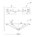
- FIG. 5 is a flowchart depicting a method 500 for detection of power swing in an electrical power system (such as 100 ), in accordance with another embodiment of the invention.
- Steps 502 and 504 are same as steps 402 and 404 , respectively of the method 400 .
- I S obtained at step 504 is compared with a current threshold value (I min ).
- a comparison module such as 218 ) detects power swing by comparing the magnitude of I S with I min .
- steps 508 to 512 are executed. Steps 508 to 512 are same as steps 406 to 410 , respectively, of the method 400 .
- the comparison module may be configured to notify the SAE and detection modules to estimate the value of ⁇ and to detect power swing based on the estimated value of ⁇ as described in steps 406 to 410 .
- the SAE and detection modules may use ⁇ dot over ( ⁇ ) ⁇ as a function of the P and Q to detect power swing.
- the detection module may be configured to detect the power swing based on the estimated ⁇ and ⁇ dot over ( ⁇ ) ⁇ .
- steps 514 to 520 are executed, in accordance with some embodiments.
- a real power value (P) is determined based on the obtained V S and I S .
- a maximum magnitude of power (P max ) transmitted from the source-end generator to the receiving-end generator is determined.
- the comparison module may be configured to send modification signals to the SAE and detection modules to modify the configurations of these modules in order to compute a different swing angle using a different approach.
- the modification signal received at the SAE module may trigger the SAE module to change its configuration to estimate a second swing angle ( ⁇ 1 ) between E S and E R as a function of the determined P and P max .
- ⁇ 1 may be determined using equation 20.
- step 520 when the obtained I S is less than the I min , power swing is detected based on estimated ⁇ 1 .
- the modification signal received at the detection module may trigger the detection module to change its configuration to detect the power swing based on estimated ⁇ 1 .
- the modification signal received at the detection module 212 triggers the detection module 212 to change its configuration to detect the power swing based on ⁇ 1 and a rate of change of ⁇ 1 ( ⁇ dot over ( ⁇ ) ⁇ 1 ).
- the SAE module 210 is configured to additionally estimate ⁇ dot over ( ⁇ ) ⁇ 1 using equation 21.
- the comparison module when the obtained I S is less than the I min , the comparison module is configured to send a deactivation signal to the SAE and detection modules for deactivation of these two modules. Deactivation of SAE and detection modules may result in discontinuing the process of estimation of ⁇ and detection of power swing.
- the devices, systems, and methods in accordance with embodiments of the invention may obviate the need for remote measurements (and hence obviate the need for communication required with remote components such as receiving-end generators and associated components) for power swing detection using the swing detection scheme in various embodiments.
- Local measurements and one or more system parameters are used in various embodiments for power swing detection.
- Various embodiments may be implemented for generator protection or transmission-level OOS protection. Certain embodiments provide approaches to accurately detect power swing even when the value of ⁇ is small.
- the devices, systems, and methods described in various embodiments of the invention may be applied to any type of protection device, and is not limited to UR family of protection.
- Various embodiments of the invention are not limited to use in application areas such as an electric grid or a microgrid, and may be extended to any other type of application areas in the electrical power system.
Abstract
Description
where, E is an internal voltage of a source-end generator
where, {dot over (S)} is a rate of change of S.
where,
P(t(k)) represents a real power measured at a time instance t(k),
P(t(k−1)) represents a real power measured at a time instance t(k−1); t(k−1) is a time instance prior to t(k),
Q(t(k)) represents a reactive power measured at the time instance t(k), and
Q(t(k−1)) represents a reactive power measured at the time instance t(k−1)
where, θmax and {dot over (θ)}max are maximum allowed swing angle and maximum allowed rate of change of swing angle, respectively.
Claims (17)
Priority Applications (6)
| Application Number | Priority Date | Filing Date | Title |
|---|---|---|---|
| US13/968,684 US10024920B2 (en) | 2013-08-16 | 2013-08-16 | Systems and methods for swing angle estimation in an electrical power system |
| JP2014154365A JP6397249B2 (en) | 2013-08-16 | 2014-07-30 | System and method for fluctuation angle estimation in power systems |
| CA2858611A CA2858611C (en) | 2013-08-16 | 2014-08-07 | Systems and methods for swing angle estimation in an electrical power system |
| EP14180548.1A EP2840674B1 (en) | 2013-08-16 | 2014-08-11 | Systems and methods for power swing angle estimation in an electrical power system |
| CN201410401864.4A CN104377722B (en) | 2013-08-16 | 2014-08-15 | The system and method estimated for pivot angle in electric system |
| US14/519,526 US10436823B2 (en) | 2013-08-16 | 2014-10-21 | Systems and methods for swing angle estimation in an electrical power system |
Applications Claiming Priority (1)
| Application Number | Priority Date | Filing Date | Title |
|---|---|---|---|
| US13/968,684 US10024920B2 (en) | 2013-08-16 | 2013-08-16 | Systems and methods for swing angle estimation in an electrical power system |
Related Child Applications (1)
| Application Number | Title | Priority Date | Filing Date |
|---|---|---|---|
| US14/519,526 Continuation-In-Part US10436823B2 (en) | 2013-08-16 | 2014-10-21 | Systems and methods for swing angle estimation in an electrical power system |
Publications (2)
| Publication Number | Publication Date |
|---|---|
| US20150051850A1 US20150051850A1 (en) | 2015-02-19 |
| US10024920B2 true US10024920B2 (en) | 2018-07-17 |
Family
ID=51298658
Family Applications (1)
| Application Number | Title | Priority Date | Filing Date |
|---|---|---|---|
| US13/968,684 Active 2036-06-18 US10024920B2 (en) | 2013-08-16 | 2013-08-16 | Systems and methods for swing angle estimation in an electrical power system |
Country Status (5)
| Country | Link |
|---|---|
| US (1) | US10024920B2 (en) |
| EP (1) | EP2840674B1 (en) |
| JP (1) | JP6397249B2 (en) |
| CN (1) | CN104377722B (en) |
| CA (1) | CA2858611C (en) |
Families Citing this family (4)
| Publication number | Priority date | Publication date | Assignee | Title |
|---|---|---|---|---|
| US9909940B2 (en) * | 2015-04-27 | 2018-03-06 | General Electric Company | System and method for non-invasive generator damping torque estimation |
| JP6787181B2 (en) * | 2017-02-28 | 2020-11-18 | 株式会社Soken | Relay device |
| CN108599270A (en) * | 2018-04-27 | 2018-09-28 | 国家电网公司东北分部 | A kind of electrical power system wide-area coordination consumption method considering wind-powered electricity generation randomness |
| WO2023087226A1 (en) * | 2021-11-18 | 2023-05-25 | Abb Schweiz Ag | Method of determining fault of power system |
Citations (22)
| Publication number | Priority date | Publication date | Assignee | Title |
|---|---|---|---|---|
| JPH03257386A (en) | 1990-03-07 | 1991-11-15 | Toshiba Corp | Preventing method of false determination of estimation of power swing of generator |
| US5731943A (en) | 1996-01-04 | 1998-03-24 | Schweitzer Engineering Laboratories, Inc. | Protective relay having out-of-step logic capability |
| EP0869599A2 (en) | 1997-04-02 | 1998-10-07 | Kabushiki Kaisha Toshiba | Method and apparatus for detecting out-of-step in electric power system |
| US6104182A (en) * | 1997-10-15 | 2000-08-15 | Siemens Ag | Method of deriving a signal indicating an oscillation in an electric power supply system |
| US6476521B1 (en) | 2000-05-31 | 2002-11-05 | Abb Ab | Power oscillation protection |
| CN1429043A (en) | 2001-12-28 | 2003-07-09 | 致福股份有限公司 | Method for locking user's identification card and mobile telephone by using short message |
| US20060067095A1 (en) * | 2004-09-29 | 2006-03-30 | Daqing Hou | Systems and methods for protection of electrical networks |
| JP4092617B2 (en) | 2001-12-03 | 2008-05-28 | 学校法人日本大学 | Step-out detection method and apparatus for power system |
| CN101807789A (en) | 2009-02-18 | 2010-08-18 | 上海电机学院 | Out-of-step protection method for synchronous motor |
| US20110022240A1 (en) | 2009-07-23 | 2011-01-27 | Athula Dayanarth Rajapaske | Rotor Angle Stability Prediction Using Post Disturbance Voltage Trajectories |
| US7930117B2 (en) | 2007-09-28 | 2011-04-19 | Schweitzer Engineering Laboratories, Inc. | Systems and methods for power swing and out-of-step detection using time stamped data |
| US20110102952A1 (en) * | 2008-06-26 | 2011-05-05 | Siemens Aktiengesellschaft | Method for production of an oscillating signal and of an electrical protection device or measurement instrument having an oscillation identification device |
| US20120123602A1 (en) | 2010-11-17 | 2012-05-17 | Electric Power Research Institute, Inc. | Application of phasor measurement units (pmu) for controlled system separation |
| US8207708B2 (en) | 2007-03-23 | 2012-06-26 | Komatsu Ltd. | Power generation control method of hybrid construction machine and hybrid construction machine |
| US20120292904A1 (en) | 2010-01-26 | 2012-11-22 | Tarnowski German Claudio | Method for emulation of synchronous machine |
| US8340930B2 (en) | 2009-06-15 | 2012-12-25 | Abb Technology Ag | Arrangement for protecting equipment of a power system |
| US8369055B2 (en) | 2007-12-13 | 2013-02-05 | Areva T&D Uk Ltd | Method for setting free detection of out of step condition in electrical power system |
| US20130066480A1 (en) | 2011-09-07 | 2013-03-14 | Quanta Associates, L.P | Real-time monitoring of electric power system voltage stability margins |
| US20140032138A1 (en) | 2012-07-24 | 2014-01-30 | Binod Shrestha | Apparatus and method for out-of-step protection using the analysis of trajectories of electrical measurements in state plane |
| US20140071565A1 (en) | 2011-05-06 | 2014-03-13 | Siemens Aktiengesellschaft | Method and protective device for detecting a symmetrical short-circuit in a multiphase electrical power supply network |
| US20140118864A1 (en) | 2012-10-31 | 2014-05-01 | General Electric Company | Method and system for power swing detection in a generator |
| US20150051852A1 (en) | 2013-08-16 | 2015-02-19 | General Electric Company | Systems and methods for swing angle estimation in an electrical power system |
Family Cites Families (6)
| Publication number | Priority date | Publication date | Assignee | Title |
|---|---|---|---|---|
| JPS61170667A (en) * | 1985-01-25 | 1986-08-01 | Kansai Electric Power Co Inc:The | Method for estimating voltage and reactance of electric power system |
| JPH08265979A (en) * | 1995-03-22 | 1996-10-11 | Tokyo Electric Power Co Inc:The | External reactance estimator for power system |
| JPH0946908A (en) * | 1995-07-28 | 1997-02-14 | Toshiba Corp | Stabilizing equipment of power system |
| JP3174525B2 (en) * | 1997-03-07 | 2001-06-11 | 三菱電機株式会社 | Modeling method, prediction method, and system stabilization control method |
| JPH11289669A (en) * | 1998-03-31 | 1999-10-19 | Tokyo Electric Power Co Inc:The | Power system stabilizing apparatus |
| US7710729B2 (en) * | 2007-07-27 | 2010-05-04 | British Columbia Transmission Corporation | Method and system of real-time estimation of transmission line parameters in on-line power flow calculations |
-
2013
- 2013-08-16 US US13/968,684 patent/US10024920B2/en active Active
-
2014
- 2014-07-30 JP JP2014154365A patent/JP6397249B2/en active Active
- 2014-08-07 CA CA2858611A patent/CA2858611C/en active Active
- 2014-08-11 EP EP14180548.1A patent/EP2840674B1/en active Active
- 2014-08-15 CN CN201410401864.4A patent/CN104377722B/en active Active
Patent Citations (23)
| Publication number | Priority date | Publication date | Assignee | Title |
|---|---|---|---|---|
| JPH03257386A (en) | 1990-03-07 | 1991-11-15 | Toshiba Corp | Preventing method of false determination of estimation of power swing of generator |
| US5731943A (en) | 1996-01-04 | 1998-03-24 | Schweitzer Engineering Laboratories, Inc. | Protective relay having out-of-step logic capability |
| EP0869599A2 (en) | 1997-04-02 | 1998-10-07 | Kabushiki Kaisha Toshiba | Method and apparatus for detecting out-of-step in electric power system |
| US6104182A (en) * | 1997-10-15 | 2000-08-15 | Siemens Ag | Method of deriving a signal indicating an oscillation in an electric power supply system |
| US6476521B1 (en) | 2000-05-31 | 2002-11-05 | Abb Ab | Power oscillation protection |
| JP4092617B2 (en) | 2001-12-03 | 2008-05-28 | 学校法人日本大学 | Step-out detection method and apparatus for power system |
| CN1429043A (en) | 2001-12-28 | 2003-07-09 | 致福股份有限公司 | Method for locking user's identification card and mobile telephone by using short message |
| US20060067095A1 (en) * | 2004-09-29 | 2006-03-30 | Daqing Hou | Systems and methods for protection of electrical networks |
| US7457088B2 (en) | 2004-09-29 | 2008-11-25 | Schweitzer Engineering Laboratories, Inc. | Systems and methods for protection of electrical networks |
| US8207708B2 (en) | 2007-03-23 | 2012-06-26 | Komatsu Ltd. | Power generation control method of hybrid construction machine and hybrid construction machine |
| US7930117B2 (en) | 2007-09-28 | 2011-04-19 | Schweitzer Engineering Laboratories, Inc. | Systems and methods for power swing and out-of-step detection using time stamped data |
| US8369055B2 (en) | 2007-12-13 | 2013-02-05 | Areva T&D Uk Ltd | Method for setting free detection of out of step condition in electrical power system |
| US20110102952A1 (en) * | 2008-06-26 | 2011-05-05 | Siemens Aktiengesellschaft | Method for production of an oscillating signal and of an electrical protection device or measurement instrument having an oscillation identification device |
| CN101807789A (en) | 2009-02-18 | 2010-08-18 | 上海电机学院 | Out-of-step protection method for synchronous motor |
| US8340930B2 (en) | 2009-06-15 | 2012-12-25 | Abb Technology Ag | Arrangement for protecting equipment of a power system |
| US20110022240A1 (en) | 2009-07-23 | 2011-01-27 | Athula Dayanarth Rajapaske | Rotor Angle Stability Prediction Using Post Disturbance Voltage Trajectories |
| US20120292904A1 (en) | 2010-01-26 | 2012-11-22 | Tarnowski German Claudio | Method for emulation of synchronous machine |
| US20120123602A1 (en) | 2010-11-17 | 2012-05-17 | Electric Power Research Institute, Inc. | Application of phasor measurement units (pmu) for controlled system separation |
| US20140071565A1 (en) | 2011-05-06 | 2014-03-13 | Siemens Aktiengesellschaft | Method and protective device for detecting a symmetrical short-circuit in a multiphase electrical power supply network |
| US20130066480A1 (en) | 2011-09-07 | 2013-03-14 | Quanta Associates, L.P | Real-time monitoring of electric power system voltage stability margins |
| US20140032138A1 (en) | 2012-07-24 | 2014-01-30 | Binod Shrestha | Apparatus and method for out-of-step protection using the analysis of trajectories of electrical measurements in state plane |
| US20140118864A1 (en) | 2012-10-31 | 2014-05-01 | General Electric Company | Method and system for power swing detection in a generator |
| US20150051852A1 (en) | 2013-08-16 | 2015-02-19 | General Electric Company | Systems and methods for swing angle estimation in an electrical power system |
Non-Patent Citations (13)
| Title |
|---|
| Benmouyal et al., "Zero-Setting Power-Swing Blocking Protection", Schweitzer Engineering Laboratories, Inc, 2004, pp. 1-29. |
| C. Liu et al, "Application of a Novel Fuzzy Neural Network to Real-Time Transient Stability Swings Prediction Based on Synchronized Phasor Measurements," IEEE Transactions on Power Systems, vol. 14, Issue No. 2, May 1999. |
| Danku et al., "Fast Prediction of the Power-Swing Curve Across Transmission Lines During Wide Area Disturbances", Power Systems Conference, PSC '09., Mar. 10-13, 2009, Location: Clemson, SC, pp. 1-5. |
| European Search Report and Opinion issued in connection with corresponding EP Application No. 14180548.1 dated Aug. 28, 2015. |
| European Search Report and Opinion issued in connection with related EP Application No. 15190082.6 dated Aug. 18, 2016. |
| Fischer et al., "Do System Impedances Really Affect Power Swings-Applying Power Swing Protection Elements Without Complex System Studies", Previously presented at the 2012 Texas A&M Conference for Protective Relay Engineers, Mar. 15, 2013, pp. 1-12. |
| Fischer et al., "Do System Impedances Really Affect Power Swings—Applying Power Swing Protection Elements Without Complex System Studies", Previously presented at the 2012 Texas A&M Conference for Protective Relay Engineers, Mar. 15, 2013, pp. 1-12. |
| Khoradshadi-Zadeh, "Evaluation and Performance Comparison of Power Swing Detection Algorithms", IEEE Power Engineering Society General Meeting, vol. 2, Jun. 12-16, 2005, pp. 1842-1848. |
| Machine Translation and Copy of First Office Action and Search issued in connection with corresponding CN Application No. 201410401864.4 dated Aug. 31, 2017. |
| Mechraoui A et al., "A New Blocking Principle With Phase and Earth Fault Detection During Fast Power Swings for Distance Protection", IEEE Transactions on Power Delivery, IEEE Service center, New York, vol. 10, Issue No. 3, pp. 1242-1248, Jul. 1, 1995. |
| Paudyal et al. "Application of Equal Area Criterion Conditions in the Time Domain for Out-of-Step Protection", IEEE Transactions on Power Delivery, vol. No. 25, Issue No. 02, pp. 600-609, Apr. 2010. |
| Segui T et al., "Fundamental Basis for Distance Relaying with Parametrical Estimation", IEEE Transactions on Power Delivery, New York, vol. No. 15, Issue No. 2, Apr. 1, 2000. |
| Stanton et al. "A Center-of-Inertia Transform Applied to Transient Responses of Nonlinear Power Systems", Proceedings of the Twenty-First Annual North-American Power Symposium, pp. 205-210, Oct. 1989. |
Also Published As
| Publication number | Publication date |
|---|---|
| CN104377722A (en) | 2015-02-25 |
| CA2858611C (en) | 2022-01-18 |
| JP6397249B2 (en) | 2018-09-26 |
| EP2840674B1 (en) | 2020-12-02 |
| JP2015037378A (en) | 2015-02-23 |
| CA2858611A1 (en) | 2015-02-16 |
| EP2840674A2 (en) | 2015-02-25 |
| EP2840674A3 (en) | 2015-09-30 |
| US20150051850A1 (en) | 2015-02-19 |
| CN104377722B (en) | 2019-11-22 |
Similar Documents
| Publication | Publication Date | Title |
|---|---|---|
| US10436823B2 (en) | Systems and methods for swing angle estimation in an electrical power system | |
| Laaksonen | Advanced islanding detection functionality for future electricity distribution networks | |
| Alinezhad et al. | Out-of-step protection based on equal area criterion | |
| US11056874B2 (en) | Fault detection and protection during steady state using traveling waves | |
| US8773829B2 (en) | Method and system for power swing detection in a generator | |
| Meghwani et al. | A new protection scheme for DC microgrid using line current derivative | |
| US10833507B2 (en) | Island detection and control of a microgrid | |
| Ten et al. | Evaluation of ROCOF relay performances on networks with distributed generation | |
| US9494635B2 (en) | Islanding detection in electricity distribution network | |
| EP2645517B1 (en) | Improvement for islanding detection reliability in electricity distribution network | |
| Habib et al. | Decentralized multi-agent system for protection and the power restoration process in microgrids | |
| US10024920B2 (en) | Systems and methods for swing angle estimation in an electrical power system | |
| Mazloomzadeh et al. | Islanding detection using synchronized measurement in smart microgrids | |
| Ravikumar et al. | State-of-the-art islanding detection and decoupling systems for utility and industrial power systems | |
| Bugdal et al. | Performance analysis of the ROCOF and Vector Shift methods using a dynamic protection modelling approach | |
| Cintuglu et al. | Islanding detection in microgrids | |
| EP3469385A1 (en) | Overcurrent element in time domain | |
| Conti | Protection issues and state of the art for microgrids with inverter-interfaced distributed generators | |
| Pena et al. | Synchrophasor-based anti-islanding detection | |
| Laaksonen | IED functionalities fulfilling future smart grid requirements | |
| Holder et al. | Investigation of transmission line protection performance in an electric grid with electronically coupled generation | |
| CA2907443C (en) | Systems and methods for swing angle estimation in an electrical power system | |
| Olofsson | Transmission line protection performance in presence of power electronic-interfaced devices: Impact and needed countermeasures in the Swedish transmission system |
Legal Events
| Date | Code | Title | Description |
|---|---|---|---|
| AS | Assignment |
Owner name: GENERAL ELECTRIC COMPANY, NEW YORK Free format text: ASSIGNMENT OF ASSIGNORS INTEREST;ASSIGNORS:PAN, YAN;PREMERLANI, WILLIAM JAMES;REEL/FRAME:031025/0820 Effective date: 20130813 |
|
| STCF | Information on status: patent grant |
Free format text: PATENTED CASE |
|
| MAFP | Maintenance fee payment |
Free format text: PAYMENT OF MAINTENANCE FEE, 4TH YEAR, LARGE ENTITY (ORIGINAL EVENT CODE: M1551); ENTITY STATUS OF PATENT OWNER: LARGE ENTITY Year of fee payment: 4 |
|
| AS | Assignment |
Owner name: GE INFRASTRUCTURE TECHNOLOGY LLC, SOUTH CAROLINA Free format text: ASSIGNMENT OF ASSIGNORS INTEREST;ASSIGNOR:GENERAL ELECTRIC COMPANY;REEL/FRAME:065727/0001 Effective date: 20231110 |