EP2500980A1 - Crimping terminal and method for crimping terminal - Google Patents
Crimping terminal and method for crimping terminal Download PDFInfo
- Publication number
- EP2500980A1 EP2500980A1 EP10829832A EP10829832A EP2500980A1 EP 2500980 A1 EP2500980 A1 EP 2500980A1 EP 10829832 A EP10829832 A EP 10829832A EP 10829832 A EP10829832 A EP 10829832A EP 2500980 A1 EP2500980 A1 EP 2500980A1
- Authority
- EP
- European Patent Office
- Prior art keywords
- conductor
- press bond
- crimp pieces
- electric wire
- pair
- Prior art date
- Legal status (The legal status is an assumption and is not a legal conclusion. Google has not performed a legal analysis and makes no representation as to the accuracy of the status listed.)
- Withdrawn
Links
Images


Classifications
-
- H—ELECTRICITY
- H01—ELECTRIC ELEMENTS
- H01R—ELECTRICALLY-CONDUCTIVE CONNECTIONS; STRUCTURAL ASSOCIATIONS OF A PLURALITY OF MUTUALLY-INSULATED ELECTRICAL CONNECTING ELEMENTS; COUPLING DEVICES; CURRENT COLLECTORS
- H01R43/00—Apparatus or processes specially adapted for manufacturing, assembling, maintaining, or repairing of line connectors or current collectors or for joining electric conductors
- H01R43/04—Apparatus or processes specially adapted for manufacturing, assembling, maintaining, or repairing of line connectors or current collectors or for joining electric conductors for forming connections by deformation, e.g. crimping tool
- H01R43/048—Crimping apparatus or processes
-
- H—ELECTRICITY
- H01—ELECTRIC ELEMENTS
- H01R—ELECTRICALLY-CONDUCTIVE CONNECTIONS; STRUCTURAL ASSOCIATIONS OF A PLURALITY OF MUTUALLY-INSULATED ELECTRICAL CONNECTING ELEMENTS; COUPLING DEVICES; CURRENT COLLECTORS
- H01R4/00—Electrically-conductive connections between two or more conductive members in direct contact, i.e. touching one another; Means for effecting or maintaining such contact; Electrically-conductive connections having two or more spaced connecting locations for conductors and using contact members penetrating insulation
- H01R4/10—Electrically-conductive connections between two or more conductive members in direct contact, i.e. touching one another; Means for effecting or maintaining such contact; Electrically-conductive connections having two or more spaced connecting locations for conductors and using contact members penetrating insulation effected solely by twisting, wrapping, bending, crimping, or other permanent deformation
- H01R4/18—Electrically-conductive connections between two or more conductive members in direct contact, i.e. touching one another; Means for effecting or maintaining such contact; Electrically-conductive connections having two or more spaced connecting locations for conductors and using contact members penetrating insulation effected solely by twisting, wrapping, bending, crimping, or other permanent deformation by crimping
- H01R4/183—Electrically-conductive connections between two or more conductive members in direct contact, i.e. touching one another; Means for effecting or maintaining such contact; Electrically-conductive connections having two or more spaced connecting locations for conductors and using contact members penetrating insulation effected solely by twisting, wrapping, bending, crimping, or other permanent deformation by crimping for cylindrical elongated bodies, e.g. cables having circular cross-section
- H01R4/184—Electrically-conductive connections between two or more conductive members in direct contact, i.e. touching one another; Means for effecting or maintaining such contact; Electrically-conductive connections having two or more spaced connecting locations for conductors and using contact members penetrating insulation effected solely by twisting, wrapping, bending, crimping, or other permanent deformation by crimping for cylindrical elongated bodies, e.g. cables having circular cross-section comprising a U-shaped wire-receiving portion
-
- H—ELECTRICITY
- H01—ELECTRIC ELEMENTS
- H01R—ELECTRICALLY-CONDUCTIVE CONNECTIONS; STRUCTURAL ASSOCIATIONS OF A PLURALITY OF MUTUALLY-INSULATED ELECTRICAL CONNECTING ELEMENTS; COUPLING DEVICES; CURRENT COLLECTORS
- H01R4/00—Electrically-conductive connections between two or more conductive members in direct contact, i.e. touching one another; Means for effecting or maintaining such contact; Electrically-conductive connections having two or more spaced connecting locations for conductors and using contact members penetrating insulation
- H01R4/10—Electrically-conductive connections between two or more conductive members in direct contact, i.e. touching one another; Means for effecting or maintaining such contact; Electrically-conductive connections having two or more spaced connecting locations for conductors and using contact members penetrating insulation effected solely by twisting, wrapping, bending, crimping, or other permanent deformation
- H01R4/18—Electrically-conductive connections between two or more conductive members in direct contact, i.e. touching one another; Means for effecting or maintaining such contact; Electrically-conductive connections having two or more spaced connecting locations for conductors and using contact members penetrating insulation effected solely by twisting, wrapping, bending, crimping, or other permanent deformation by crimping
- H01R4/188—Electrically-conductive connections between two or more conductive members in direct contact, i.e. touching one another; Means for effecting or maintaining such contact; Electrically-conductive connections having two or more spaced connecting locations for conductors and using contact members penetrating insulation effected solely by twisting, wrapping, bending, crimping, or other permanent deformation by crimping having an uneven wire-receiving surface to improve the contact
-
- H—ELECTRICITY
- H01—ELECTRIC ELEMENTS
- H01R—ELECTRICALLY-CONDUCTIVE CONNECTIONS; STRUCTURAL ASSOCIATIONS OF A PLURALITY OF MUTUALLY-INSULATED ELECTRICAL CONNECTING ELEMENTS; COUPLING DEVICES; CURRENT COLLECTORS
- H01R43/00—Apparatus or processes specially adapted for manufacturing, assembling, maintaining, or repairing of line connectors or current collectors or for joining electric conductors
- H01R43/04—Apparatus or processes specially adapted for manufacturing, assembling, maintaining, or repairing of line connectors or current collectors or for joining electric conductors for forming connections by deformation, e.g. crimping tool
- H01R43/058—Crimping mandrels
Definitions
- the present invention relates to a press bond terminal of an open barrel type having a conductor press bond part with a U-shaped cross section used in, for example, an electrical equipment system of an automobile, and a method for pressing and bonding a terminal using the press bond terminal.
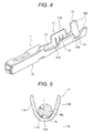
- Fig. 4 is a perspective view showing a configuration of a conventional press bond terminal described in, for example, Patent Reference 1.
- This press bond terminal 1 includes an electrical connection part 10 connected to a terminal of the other connector side (not shown) in the front of a longitudinal direction (also a longitudinal direction of a conductor of an electric wire connected) of the terminal, and includes a conductor press bond part 11 crimped to the conductor in which the distal end of the electric wire (not shown) is exposed in the back of the electrical connection part 10, and further includes a coating crimp part 12 crimped to the portion having an insulating coating in the electric wire in the back of the conductor press bond part 11.
- a first joining part 13 for joining the electrical connection part 10 to the conductor press bond part 11 is included between the electrical connection part 10 and the conductor press bond part 11
- a second joining part 14 for joining the conductor press bond part 11 to the coating crimp part 12 is included between the conductor press bond part 11 and the coating crimp part 12.
- the conductor press bond part 11 is formed in substantially a U-shaped cross section opened upward by a base plate 11A and a pair of conductor crimp pieces 11B, 11B which is extended upward from both right and left lateral edges of the base plate 11A and is crimped so as to wrap the conductor of the electric wire disposed on an inner surface of the base plate 11A.
- the coating crimp part 12 is formed in substantially a U-shaped cross section by a base plate 12A and a pair of coating crimp pieces 12B, 12B which is extended upward from both right and left lateral edges of the base plate 12A and is crimped so as to wrap the electric wire (that is, the portion having the insulating coating) disposed on an inner surface of the base plate 12A.
- an inner surface of the conductor press bond part 11 is provided with plural serrations 18 with a recessed groove shape extending in a direction orthogonal to the longitudinal direction (that is, the longitudinal direction of the terminal) of the conductor of the electric wire.
- the press bond terminal In the case of pressing and bonding the conductor press bond part 11 of this press bond terminal 1 to the conductor of the distal end of the electric wire, the press bond terminal is placed on a placement surface (that is, an upper surface) of a lower mold (that is, an anvil) (not shown) and also, the conductor of the distal end of the electric wire is inserted between the conductor crimp pieces of the conductor press bond part and a conductor Wa is placed on an upper surface of the base plate 11A as shown in Fig. 5 .
- the range from the base plate 11A to the root of a pair of conductor crimp pieces 11B, 11B is formed as a curved wall 11H with a radius R of curvature larger than a radius r of the conductor Wa, with the result that the conductor Wa guided between the conductor crimp pieces 11B, 11B is placed in a state of making contact with an inner surface of the base plate 11A of the conductor press bond part 11.
- the distal end sides of the conductor crimp pieces are gradually laid inward by a guide inclined surface of the upper mold and by further downward moving the upper mold (that is, the crimper) relatively with respect to the lower mold, finally, the distal ends of the conductor crimp pieces 11B are rounded so as to be folded back to the side of the conductor Wa by a curved surface ranging from the guide inclined surface of the upper mold to a chevron-shaped part of the center, and the distal ends of the conductor crimp pieces 11B are mutually bitten into the conductor Wa while being rubbed together and thereby, the conductor crimp pieces 11B are crimped so as to wrap the conductor Wa.
- the conductor press bond part 11 of the press bond terminal 1 can be connected to the conductor Wa of the electric wire by press bonding.
- the coating crimp pieces 12B are gradually bent inward and are crimped to the portion having the insulating coating in the electric wire. This allows the press bond terminal 1 to be electrically and mechanically connected to the electric wire.
- the radius R of curvature of the curved wall 11H constructing the range from the base plate 11A of the conductor press bond part 11 to the root of a pair of conductor crimp pieces 11B, 11B is set so as to become larger than the radius r of the conductor Wa of the electric wire wrapped inward, so that a pressure of contact between the terminal and the conductor at the time of obtaining a press bond state finally does not become very high and there is a problem that contact resistance tends to become unstable.
- an object of the invention is to provide a press bond terminal capable of improving electrical connection performance by increasing a pressure of contact between an electric wire and the terminal, and a method for pressing and bonding the terminal using the press bond terminal.
- the radius R of curvature of the inner surface of the curved wall (that is, the range from the base plate of the conductor press bond part to the root of a pair of conductor crimp pieces) is set smaller than the radius r of the conductor of the electric wire, so that when the conductor of the electric wire is inserted between the conductor crimp pieces before press bonding, the conductor abuts on inner surfaces of the conductor crimp pieces in the middle of a height direction of the conductor crimp pieces and stops, and is held in a state of no contact with the base plate of the conductor press bond part.
- the conductor of the electric wire is pushed on the base plate of the conductor press bond part and accordingly, the curved wall (the range from the base plate to the root of the conductor crimp pieces) is outward pushed out by being subjected to a pressure from the conductor and a pressure from the conductor crimp pieces. Then, in a state of outward pushing out the curved wall, the distal ends of the conductor crimp pieces are finally crimped so as to be bitten into the conductor to complete the press bonding.
- the press bond terminal of (1) described above is pressed and bonded to the conductor of the electric wire using the upper mold and the lower mold, so that the spring-back force can effectively be generated with respect to the terminal, and the terminal can be connected to the electric wire by stable contact resistance.
- Figs. 1(a) and 1(b) are main configuration diagrams of a press bond terminal of an embodiment
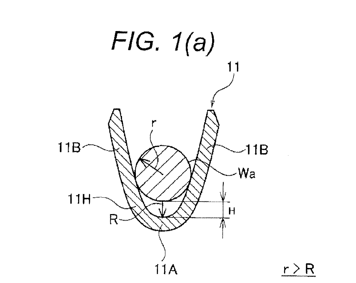
- Fig. 1(a) is a sectional view showing a relation between a conductor press bond part of the press bond terminal and a conductor of an electric wire
- Fig. 1(b) is a diagram showing an initial stage of an operation in the case of pressing and bonding the conductor press bond part to the conductor
- Figs. 2(a) to 2(c) are step explanatory diagrams in the case of pressing and bonding the same press bond terminal to the conductor
- Fig. 2(a) is a diagram of the conductor press bond part showing a state in which conductor crimp pieces start to be laid inward
- FIG. 2(b) is a diagram showing a state in which the conductor crimp pieces start to be rounded inward
- Fig. 2(c) is a diagram showing a state in which the conductor crimp pieces are rounded so as to be folded back to the conductor side
- Fig. 3 is a sectional view showing a state of finally pressing and bonding the same press bond terminal to the conductor, and a chain line in the drawing exaggeratedly shows the original shape of the conductor press bond part of the press bond terminal of the embodiment, and a two-dot chain line in the drawing exaggeratedly shows the original shape of a conductor press bond part of a conventional general press bond terminal.
- a conductor press bond part 11 connected by being pressed and bonded to the distal end of a conductor Wa of an electric wire is formed in substantially a U-shaped cross section opened upward by a base plate 11A and a pair of conductor crimp pieces 11B, 11B extended upward from both right and left lateral edges of the base plate 11A as shown in Fig. 1(a) .
- the range from the base plate 11A to the root of a pair of conductor crimp pieces 11B, 11B is formed as a curved wall 11H with substantially a circular arc shape and when a radius of curvature of an inner surface of the curved wall 11H is R and a radius of the conductor Wa of the electric wire is r, the curved wall 11H is characterized by being set so as to satisfy R ⁇ r.
- the conductor press bond part 11 of the press bond terminal is arranged between a lower mold (an anvil) 101 and an upper mold (a crimper) 102 of a press bond device and also, the distal end of the conductor Wa of the electric wire is inserted between a pair of conductor crimp pieces 11B, 11B.
- the radius R of curvature of the inner surface of the curved wall 11H (that is, the range from the base plate 11A of the conductor press bond part 11 to the root of a pair of conductor crimp pieces 11B, 11B) is set smaller than the radius r of the conductor of the electric wire, so that the conductor Wa abuts on inner surfaces of the conductor crimp pieces 11B in the middle of a height direction of the conductor crimp pieces 11B and stops, and is held in a state of no contact with the base plate 11A of the conductor press bond part 11.
- the conductor is held in a state in which there is a gap H between the conductor Wa and an inner surface of the base plate 11A.
- the conductor Wa of the electric wire is pushed on the base plate 11A of the conductor press bond part 11 and accordingly, the curved wall 11H (the range from the base plate 11A to the root of the conductor crimp pieces 11B) is outward pushed out by being subjected to a pressure from the conductor Wa and a pressure from the conductor crimp pieces 11B. Then, in a state of outward pushing out the curved wall 11H, the distal ends of the conductor crimp pieces 11B are finally crimped so as to be bitten into the conductor Wa to complete the press bonding.
- a great spring-back force by which the curved wall 11H returns to the original shape (that is, shape shown by 11Y) with small curvature is generated in the curved wall 11H.
- the spring-back forces S generated at shoulder parts 11C which are the boundaries between the base plate 11A and the root of the conductor crimp pieces 11B become greater than spring-back forces in the case of returning to the original shape (that is, shape shown by 11X) with large curvature like a conventional press bond terminal, and act as a contact pressure of making close contact with the conductor Wa wrapped inward, with the result that adhesion between the conductor Wa and the terminal increases and contact resistance is low to become stable.
- the spring-back force can effectively be generated with respect to the terminal, so that the terminal can be connected to the electric wire by stable contact resistance.
Landscapes
- Engineering & Computer Science (AREA)
- Manufacturing & Machinery (AREA)
- Connections Effected By Soldering, Adhesion, Or Permanent Deformation (AREA)
- Manufacturing Of Electrical Connectors (AREA)
Abstract
Description
- The present invention relates to a press bond terminal of an open barrel type having a conductor press bond part with a U-shaped cross section used in, for example, an electrical equipment system of an automobile, and a method for pressing and bonding a terminal using the press bond terminal.
-
Fig. 4 is a perspective view showing a configuration of a conventional press bond terminal described in, for example, Patent Reference 1. - This press bond terminal 1 includes an
electrical connection part 10 connected to a terminal of the other connector side (not shown) in the front of a longitudinal direction (also a longitudinal direction of a conductor of an electric wire connected) of the terminal, and includes a conductorpress bond part 11 crimped to the conductor in which the distal end of the electric wire (not shown) is exposed in the back of theelectrical connection part 10, and further includes acoating crimp part 12 crimped to the portion having an insulating coating in the electric wire in the back of the conductorpress bond part 11. Also, a first joiningpart 13 for joining theelectrical connection part 10 to the conductorpress bond part 11 is included between theelectrical connection part 10 and the conductorpress bond part 11, and a second joining part 14 for joining the conductorpress bond part 11 to thecoating crimp part 12 is included between the conductorpress bond part 11 and thecoating crimp part 12. - The conductor
press bond part 11 is formed in substantially a U-shaped cross section opened upward by abase plate 11A and a pair ofconductor crimp pieces base plate 11A and is crimped so as to wrap the conductor of the electric wire disposed on an inner surface of thebase plate 11A. Also, thecoating crimp part 12 is formed in substantially a U-shaped cross section by abase plate 12A and a pair ofcoating crimp pieces base plate 12A and is crimped so as to wrap the electric wire (that is, the portion having the insulating coating) disposed on an inner surface of thebase plate 12A. - Also, an inner surface of the conductor
press bond part 11 is provided withplural serrations 18 with a recessed groove shape extending in a direction orthogonal to the longitudinal direction (that is, the longitudinal direction of the terminal) of the conductor of the electric wire. - In the case of pressing and bonding the conductor
press bond part 11 of this press bond terminal 1 to the conductor of the distal end of the electric wire, the press bond terminal is placed on a placement surface (that is, an upper surface) of a lower mold (that is, an anvil) (not shown) and also, the conductor of the distal end of the electric wire is inserted between the conductor crimp pieces of the conductor press bond part and a conductor Wa is placed on an upper surface of thebase plate 11A as shown inFig. 5 . Normally, the range from thebase plate 11A to the root of a pair ofconductor crimp pieces curved wall 11H with a radius R of curvature larger than a radius r of the conductor Wa, with the result that the conductor Wa guided between theconductor crimp pieces base plate 11A of the conductorpress bond part 11. - By downward moving an upper mold (that is, a crimper) relatively with respect to the lower mold in this state, the distal end sides of the conductor crimp pieces are gradually laid inward by a guide inclined surface of the upper mold and by further downward moving the upper mold (that is, the crimper) relatively with respect to the lower mold, finally, the distal ends of the
conductor crimp pieces 11B are rounded so as to be folded back to the side of the conductor Wa by a curved surface ranging from the guide inclined surface of the upper mold to a chevron-shaped part of the center, and the distal ends of theconductor crimp pieces 11B are mutually bitten into the conductor Wa while being rubbed together and thereby, theconductor crimp pieces 11B are crimped so as to wrap the conductor Wa. - By the above operation, the conductor
press bond part 11 of the press bond terminal 1 can be connected to the conductor Wa of the electric wire by press bonding. In addition, similarly in thecoating crimp part 12, using the lower mold and the upper mold, thecoating crimp pieces 12B are gradually bent inward and are crimped to the portion having the insulating coating in the electric wire. This allows the press bond terminal 1 to be electrically and mechanically connected to the electric wire. -
- Patent Reference 1:
JP-A-2006-228759 Fig. 1 ) - Incidentally, in the case of the conventional press bond terminal described above, the radius R of curvature of the
curved wall 11H constructing the range from thebase plate 11A of the conductorpress bond part 11 to the root of a pair ofconductor crimp pieces - In view of the circumstances described above, an object of the invention is to provide a press bond terminal capable of improving electrical connection performance by increasing a pressure of contact between an electric wire and the terminal, and a method for pressing and bonding the terminal using the press bond terminal.
-
- (1) In order to solve the problem described above, a first aspect of the invention provides a press bond terminal having a conductor press bond part connected by being pressed and bonded to a distal end of a conductor of an electric wire, the conductor press bond part being formed in substantially a U-shaped cross section opened upward by a base plate and a pair of conductor crimp pieces extended upward from both right and left lateral edges of the base plate, the press bond terminal being electrically connected to the electric wire by inserting the conductor of the electric wire between the pair of conductor crimp pieces in the case of being pressed and bonded to the electric wire and inward rounding the pair of conductor crimp pieces to crimp the conductor crimp pieces so as to wrap the conductor with the base plate by a press bond operation of a lower mold and an upper mold of a press bond device in its insertion state, wherein a range from the base plate to the root of the pair of conductor crimp pieces is formed as a curved wall with substantially a circular arc shape and when a radius of curvature of an inner surface of the curved wall is R and a radius of the conductor of the electric wire is r, the curved wall is set so as to satisfy R<r.
-
- (2) In order to solve the problem described above, a second aspect of the invention provides a method for pressing and bonding a terminal, wherein a press bond terminal of (1) described above is arranged between an upper mold and a lower mold of a press bond device and also a distal end of a conductor of the electric wire is inserted between the pair of conductor crimp pieces and the upper mold is downward moved relatively with respect to the lower mold in its insertion state and thereby the pair of conductor crimp pieces is laid inward by action of a guide inclined surface of the upper mold and further the upper mold is downward moved relatively with respect to the lower mold and thereby the pair of conductor crimp pieces is rounded inward so as to be folded back to the conductor side by action of a curved surface ranging from the guide inclined surface of the upper mold to a chevron-shaped part of the center and finally distal ends of the conductor crimp pieces are mutually bitten into the conductor while being rubbed together and thereby both conductor crimp pieces are crimped so as to wrap the conductor with the base plate.
- According to the press bond terminal of (1) described above, the radius R of curvature of the inner surface of the curved wall (that is, the range from the base plate of the conductor press bond part to the root of a pair of conductor crimp pieces) is set smaller than the radius r of the conductor of the electric wire, so that when the conductor of the electric wire is inserted between the conductor crimp pieces before press bonding, the conductor abuts on inner surfaces of the conductor crimp pieces in the middle of a height direction of the conductor crimp pieces and stops, and is held in a state of no contact with the base plate of the conductor press bond part. When press bond processing is performed by downward moving the upper mold of the press bond device relatively with respect to the lower mold from this state, the distal ends of a pair of conductor crimp pieces are gradually laid inward by making contact with a guide inclined surface of the upper mold and by further downward moving the upper mold relatively with respect to the lower mold, the distal ends of a pair of conductor crimp pieces abut on a curved surface ranging from the guide inclined surface of the upper mold to a chevron-shaped part of the center and thereby are guided inward and are rounded so as to be folded back to the side of the conductor and, finally, the distal ends of both conductor crimp pieces are mutually bitten into the conductor while being rubbed together and thereby, both conductor crimp pieces are crimped so as to wrap the conductor with the base plate.
- In the case of that series of operations, the conductor of the electric wire is pushed on the base plate of the conductor press bond part and accordingly, the curved wall (the range from the base plate to the root of the conductor crimp pieces) is outward pushed out by being subjected to a pressure from the conductor and a pressure from the conductor crimp pieces. Then, in a state of outward pushing out the curved wall, the distal ends of the conductor crimp pieces are finally crimped so as to be bitten into the conductor to complete the press bonding.
- Therefore, in a final press bond state, a great spring-back force by which the curved wall returns to the original shape with small curvature is generated in the curved wall. Particularly, the spring-back forces generated at the boundaries (the portions called "shoulder parts") between the base plate and the root of the conductor crimp pieces act as a contact pressure of making close contact with the conductor wrapped inward, with the result that adhesion between the conductor and the terminal increases and contact resistance is low to become stable, and electrical connection performance can be improved.
- According to the method for pressing and bonding the terminal of (2) described above, the press bond terminal of (1) described above is pressed and bonded to the conductor of the electric wire using the upper mold and the lower mold, so that the spring-back force can effectively be generated with respect to the terminal, and the terminal can be connected to the electric wire by stable contact resistance.
-
- [
Fig. 1] Figs. 1(a) and 1(b) are main configuration diagrams of a press bond terminal of an embodiment of the invention, andFig. 1(a) is a sectional view showing a relation between a conductor press bond part of the press bond terminal and a conductor of an electric wire, andFig. 1(b) is a diagram showing an initial stage of an operation in the case of pressing and bonding the conductor press bond part to the conductor. - [
Fig. 2] Figs. 2(a) to 2(c) are step explanatory diagrams in the case of pressing and bonding the press bond terminal to the conductor, andFig. 2(a) is a diagram of the conductor press bond part showing a state in which conductor crimp pieces start to be laid inward, andFig. 2(b) is a diagram showing a state in which the conductor crimp pieces start to be rounded inward, andFig. 2(c) is a diagram showing a state in which the conductor crimp pieces are rounded so as to be folded back to the conductor side. - [
Fig. 3] Fig. 3 is a sectional view showing a state of finally pressing and bonding the press bond terminal to the conductor, and a chain line in the drawing shows the original shape of the conductor press bond part of the press bond terminal of the embodiment, and a two-dot chain line in the drawing shows the original shape of a conductor press bond part of a conventional general press bond terminal. - [
Fig. 4] Fig. 4 is a perspective view showing a configuration of a conventional press bond terminal. - [
Fig. 5] Fig. 5 is a diagram showing a relation between the conductor press bond part of the conventional press bond terminal and a conductor of an electric wire. - An embodiment of the invention will hereinafter be described using the drawings.
-
Figs. 1(a) and 1(b) are main configuration diagrams of a press bond terminal of an embodiment, andFig. 1(a) is a sectional view showing a relation between a conductor press bond part of the press bond terminal and a conductor of an electric wire, andFig. 1(b) is a diagram showing an initial stage of an operation in the case of pressing and bonding the conductor press bond part to the conductor, andFigs. 2(a) to 2(c) are step explanatory diagrams in the case of pressing and bonding the same press bond terminal to the conductor, andFig. 2(a) is a diagram of the conductor press bond part showing a state in which conductor crimp pieces start to be laid inward, andFig. 2(b) is a diagram showing a state in which the conductor crimp pieces start to be rounded inward, andFig. 2(c) is a diagram showing a state in which the conductor crimp pieces are rounded so as to be folded back to the conductor side.Fig. 3 is a sectional view showing a state of finally pressing and bonding the same press bond terminal to the conductor, and a chain line in the drawing exaggeratedly shows the original shape of the conductor press bond part of the press bond terminal of the embodiment, and a two-dot chain line in the drawing exaggeratedly shows the original shape of a conductor press bond part of a conventional general press bond terminal. - In the press bond terminal of the present embodiment, a conductor
press bond part 11 connected by being pressed and bonded to the distal end of a conductor Wa of an electric wire is formed in substantially a U-shaped cross section opened upward by abase plate 11A and a pair ofconductor crimp pieces base plate 11A as shown inFig. 1(a) . Then, the range from thebase plate 11A to the root of a pair ofconductor crimp pieces curved wall 11H with substantially a circular arc shape and when a radius of curvature of an inner surface of thecurved wall 11H is R and a radius of the conductor Wa of the electric wire is r, thecurved wall 11H is characterized by being set so as to satisfy R<r. - In the case of pressing and bonding this press bond terminal to the electric wire, as shown in
Fig. 1(b) , the conductorpress bond part 11 of the press bond terminal is arranged between a lower mold (an anvil) 101 and an upper mold (a crimper) 102 of a press bond device and also, the distal end of the conductor Wa of the electric wire is inserted between a pair ofconductor crimp pieces curved wall 11H (that is, the range from thebase plate 11A of the conductorpress bond part 11 to the root of a pair ofconductor crimp pieces conductor crimp pieces 11B in the middle of a height direction of theconductor crimp pieces 11B and stops, and is held in a state of no contact with thebase plate 11A of the conductorpress bond part 11. In other words, the conductor is held in a state in which there is a gap H between the conductor Wa and an inner surface of thebase plate 11A. - When press bond processing is performed by downward moving the
upper mold 102 of the press bond device relatively with respect to thelower mold 101 from this state, as shown inFig. 2(a) , the distal ends of a pair ofconductor crimp pieces inclined surface 110 of theupper mold 102 and by further downward moving theupper mold 102 relatively with respect to thelower mold 101, as shown inFigs. 2(b) and 2(c) , the distal ends of a pair ofconductor crimp pieces curved surfaces 111 ranging from the guideinclined surface 110 of the upper mold to a chevron-shaped part 112 of the center and thereby are guided inward and are rounded so as to be folded back to the side of the conductor Wa and, finally as shown inFig. 3 , the distal ends of bothconductor crimp pieces conductor crimp pieces base plate 11A. - In the case of this series of operations, the conductor Wa of the electric wire is pushed on the
base plate 11A of the conductorpress bond part 11 and accordingly, thecurved wall 11H (the range from thebase plate 11A to the root of theconductor crimp pieces 11B) is outward pushed out by being subjected to a pressure from the conductor Wa and a pressure from theconductor crimp pieces 11B. Then, in a state of outward pushing out thecurved wall 11H, the distal ends of theconductor crimp pieces 11B are finally crimped so as to be bitten into the conductor Wa to complete the press bonding. - Therefore, in a final press bond state shown in
Fig. 3 , a great spring-back force by which thecurved wall 11H returns to the original shape (that is, shape shown by 11Y) with small curvature is generated in thecurved wall 11H. Particularly, the spring-back forces S generated atshoulder parts 11C which are the boundaries between thebase plate 11A and the root of theconductor crimp pieces 11B become greater than spring-back forces in the case of returning to the original shape (that is, shape shown by 11X) with large curvature like a conventional press bond terminal, and act as a contact pressure of making close contact with the conductor Wa wrapped inward, with the result that adhesion between the conductor Wa and the terminal increases and contact resistance is low to become stable. - As described above, in the case of pressing and bonding the press bond terminal of the embodiment to the conductor Wa of the electric wire using the
upper mold 102 and thelower mold 101, the spring-back force can effectively be generated with respect to the terminal, so that the terminal can be connected to the electric wire by stable contact resistance. - The present application is based on Japanese patent application (patent application No.
2009-258534 -
- 11
- CONDUCTOR PRESS BOND PART
- 11A
- BASE PLATE
- 11B
- CONDUCTOR CRIMP PIECE
- 11H
- CURVED WALL
- 101
- LOWER MOLD
- 102
- UPPER MOLD
- 110
- GUIDE INCLINED SURFACE
- 111
- CURVED SURFACE
- 112
- CHEVRON-SHAPED PART
- Wa
- CONDUCTOR OF ELECTRIC WIRE
Claims (2)
- A press bond terminal having a conductor press bond part connected by being pressed and bonded to a distal end of a conductor of an electric wire, the conductor press bond part being formed in substantially a U-shaped cross section opened upward by a base plate and a pair of conductor crimp pieces extended upward from both right and left lateral edges of the base plate, the press bond terminal being electrically connected to the electric wire by inserting the conductor of the electric wire between the pair of conductor crimp pieces in the case of being pressed and bonded to the electric wire and inward rounding the pair of conductor crimp pieces to crimp the conductor crimp pieces so as to wrap the conductor with the base plate by a press bond operation of a lower mold and an upper mold of a press bond device in its insertion state, wherein a range from the base plate to the root of the pair of conductor crimp pieces is formed as a curved wall with substantially a circular arc shape and when a radius of curvature of an inner surface of the curved wall is R and a radius of the conductor of the electric wire is r, the curved wall is set so as to satisfy R<r.
- A method for pressing and bonding a terminal, wherein a press bond terminal as claimed in claim 1 is arranged between an upper mold and a lower mold of a press bond device and also a distal end of a conductor of the electric wire is inserted between the pair of conductor crimp pieces and the upper mold is downward moved relatively with respect to the lower mold in its insertion state and thereby the pair of conductor crimp pieces is laid inward by action of a guide inclined surface of the upper mold and further the upper mold is downward moved relatively with respect to the lower mold and thereby the pair of conductor crimp pieces is rounded inward so as to be folded back to the conductor side by action of a curved surface ranging from the guide inclined surface of the upper mold to a chevron-shaped part of the center and finally distal ends of the conductor crimp pieces are mutually bitten into the conductor while being rubbed together and thereby both conductor crimp pieces are crimped so as to wrap the conductor with the base plate.
Applications Claiming Priority (2)
| Application Number | Priority Date | Filing Date | Title |
|---|---|---|---|
| JP2009258534A JP2011103262A (en) | 2009-11-12 | 2009-11-12 | Crimping terminal and method for crimping terminal |
| PCT/JP2010/068880 WO2011058872A1 (en) | 2009-11-12 | 2010-10-25 | Crimping terminal and method for crimping terminal |
Publications (2)
| Publication Number | Publication Date |
|---|---|
| EP2500980A1 true EP2500980A1 (en) | 2012-09-19 |
| EP2500980A4 EP2500980A4 (en) | 2014-12-03 |
Family
ID=43991531
Family Applications (1)
| Application Number | Title | Priority Date | Filing Date |
|---|---|---|---|
| EP10829832.4A Withdrawn EP2500980A4 (en) | 2009-11-12 | 2010-10-25 | CRIMPING TERMINAL, AND METHOD FOR CRIMPING TERMINAL |
Country Status (5)
| Country | Link |
|---|---|
| US (1) | US9048606B2 (en) |
| EP (1) | EP2500980A4 (en) |
| JP (1) | JP2011103262A (en) |
| CN (1) | CN102598416A (en) |
| WO (1) | WO2011058872A1 (en) |
Families Citing this family (5)
| Publication number | Priority date | Publication date | Assignee | Title |
|---|---|---|---|---|
| JP5846114B2 (en) * | 2012-12-19 | 2016-01-20 | 住友電装株式会社 | Manufacturing method of electric wire with terminal and electric wire with terminal |
| JP5579342B1 (en) | 2013-02-23 | 2014-08-27 | 古河電気工業株式会社 | Cylindrical body, crimp terminal, manufacturing method thereof, and crimp terminal manufacturing apparatus |
| JP5920284B2 (en) * | 2013-05-17 | 2016-05-18 | 住友電装株式会社 | Electric wire with terminal |
| JP6421737B2 (en) * | 2015-10-21 | 2018-11-14 | 株式会社オートネットワーク技術研究所 | Manufacturing method of electric wire with terminal, crimping jig, and electric wire with terminal |
| JP6713009B2 (en) * | 2018-02-15 | 2020-06-24 | 株式会社オートネットワーク技術研究所 | Terminals and connectors |
Family Cites Families (13)
| Publication number | Priority date | Publication date | Assignee | Title |
|---|---|---|---|---|
| US3032602A (en) * | 1959-12-16 | 1962-05-01 | Gen Motors Corp | Electrical connector |
| US3404368A (en) * | 1965-08-04 | 1968-10-01 | Amp Inc | Electrical connector of the plug or socket variety |
| US4142771A (en) * | 1974-10-16 | 1979-03-06 | Amp Incorporated | Crimp-type terminal |
| JPH0754727B2 (en) * | 1991-01-25 | 1995-06-07 | 日本オートマチックマシン株式会社 | Caulking device for wire terminals |
| US5445535A (en) * | 1994-05-02 | 1995-08-29 | General Motors Corporation | Insulation displacement terminal |
| JP2001217013A (en) | 2000-02-02 | 2001-08-10 | Sumitomo Wiring Syst Ltd | Terminal fitting |
| JP3940258B2 (en) * | 2000-09-22 | 2007-07-04 | 矢崎総業株式会社 | How to connect terminals and wires |
| EP1503454B1 (en) * | 2003-07-30 | 2015-08-05 | Furukawa Electric Co. Ltd. | Terminal crimping structure for aluminium wire and producing method |
| JP4250103B2 (en) * | 2004-03-12 | 2009-04-08 | Smk株式会社 | Crimping device |
| JP4078564B2 (en) | 2006-06-02 | 2008-04-23 | 住友電装株式会社 | Female terminal fitting |
| JP2008177033A (en) * | 2007-01-18 | 2008-07-31 | Yazaki Corp | Terminal crimping device |
| JP4983467B2 (en) * | 2007-08-02 | 2012-07-25 | 住友電装株式会社 | Terminal crimping device, terminal crimped wire manufacturing method, and terminal crimped wire |
| JP2009258534A (en) | 2008-04-21 | 2009-11-05 | Sharp Corp | Flicker adjustment sheet and flicker adjustment method for display using same |
-
2009
- 2009-11-12 JP JP2009258534A patent/JP2011103262A/en not_active Abandoned
-
2010
- 2010-10-25 US US13/508,637 patent/US9048606B2/en not_active Expired - Fee Related
- 2010-10-25 EP EP10829832.4A patent/EP2500980A4/en not_active Withdrawn
- 2010-10-25 CN CN2010800492152A patent/CN102598416A/en active Pending
- 2010-10-25 WO PCT/JP2010/068880 patent/WO2011058872A1/en not_active Ceased
Also Published As
| Publication number | Publication date |
|---|---|
| WO2011058872A1 (en) | 2011-05-19 |
| US9048606B2 (en) | 2015-06-02 |
| US20120231678A1 (en) | 2012-09-13 |
| CN102598416A (en) | 2012-07-18 |
| JP2011103262A (en) | 2011-05-26 |
| EP2500980A4 (en) | 2014-12-03 |
Similar Documents
| Publication | Publication Date | Title |
|---|---|---|
| EP2495813A1 (en) | Crimp terminal | |
| EP2495814A1 (en) | Crimp terminal | |
| US10003136B2 (en) | Crimp terminal and crimping structure with respect to electrical wire thereof | |
| JP5107693B2 (en) | Crimping structure and crimping method | |
| EP2169771A1 (en) | A terminal fitting, a terminal fitting chain, a wire with a terminal fitting, a processing device therefor and a connecting method therefor | |
| EP2151893A1 (en) | A terminal fitting and a crimping method | |
| US9065190B2 (en) | Crimp terminal, crimp structure of crimp terminal, and crimping method of crimp terminal | |
| EP2309600A1 (en) | Compression terminal, splicing terminal, and electric wire compressing structure | |
| US20150364835A1 (en) | Method of manufacturing connection structural body, connection structural body, wire harness, crimping member and crimping device | |
| CN105191001A (en) | Crimping terminal | |
| JP2020107615A (en) | Cable assembly | |
| US9048606B2 (en) | Press bond terminal and method for pressing and bonding terminal | |
| US20200287300A1 (en) | Connection Terminal, Method Of Connecting Wires Using The Same And Pressing Die | |
| CN100470931C (en) | Pressure-bonding connector | |
| US20190044252A1 (en) | Wire with terminal | |
| JP2010097781A (en) | Manufacturing method of electric wire with terminal fitting, and terminal crimping device | |
| JP5506028B2 (en) | Crimping device | |
| JP2018041549A (en) | Crimp terminal | |
| CN115668646A (en) | Terminal and electric wire with terminal | |
| JP2007059304A (en) | Electric wire with terminal and manufacturing method thereof | |
| EP2187478A1 (en) | A terminal fitting, a wire connection structure and a connecting method | |
| JP5607851B2 (en) | Method for manufacturing connection structure and crimping device | |
| JP4057301B2 (en) | Flat cable connection terminal and connection method between flat cable and connection terminal | |
| JP2000058144A (en) | ID terminal | |
| JP2025186769A (en) | Conductor crimping method for crimp connection terminals |
Legal Events
| Date | Code | Title | Description |
|---|---|---|---|
| PUAI | Public reference made under article 153(3) epc to a published international application that has entered the european phase |
Free format text: ORIGINAL CODE: 0009012 |
|
| 17P | Request for examination filed |
Effective date: 20120510 |
|
| AK | Designated contracting states |
Kind code of ref document: A1 Designated state(s): AL AT BE BG CH CY CZ DE DK EE ES FI FR GB GR HR HU IE IS IT LI LT LU LV MC MK MT NL NO PL PT RO RS SE SI SK SM TR |
|
| DAX | Request for extension of the european patent (deleted) | ||
| A4 | Supplementary search report drawn up and despatched |
Effective date: 20141030 |
|
| RIC1 | Information provided on ipc code assigned before grant |
Ipc: H01R 4/18 20060101AFI20141024BHEP Ipc: H01R 43/048 20060101ALI20141024BHEP |
|
| 17Q | First examination report despatched |
Effective date: 20170117 |
|
| STAA | Information on the status of an ep patent application or granted ep patent |
Free format text: STATUS: THE APPLICATION HAS BEEN WITHDRAWN |
|
| 18W | Application withdrawn |
Effective date: 20170515 |