EP2500751B1 - Siphon drainage type rainfall remote-measurement device and method with self-compensation function - Google Patents
Siphon drainage type rainfall remote-measurement device and method with self-compensation function Download PDFInfo
- Publication number
- EP2500751B1 EP2500751B1 EP10827849.0A EP10827849A EP2500751B1 EP 2500751 B1 EP2500751 B1 EP 2500751B1 EP 10827849 A EP10827849 A EP 10827849A EP 2500751 B1 EP2500751 B1 EP 2500751B1
- Authority
- EP
- European Patent Office
- Prior art keywords
- rainfall
- water level
- siphon
- measuring tube
- siphon drainage
- Prior art date
- Legal status (The legal status is an assumption and is not a legal conclusion. Google has not performed a legal analysis and makes no representation as to the accuracy of the status listed.)
- Active
Links
- 238000000034 method Methods 0.000 title claims description 36
- 238000005259 measurement Methods 0.000 title claims description 25
- XLYOFNOQVPJJNP-UHFFFAOYSA-N water Substances O XLYOFNOQVPJJNP-UHFFFAOYSA-N 0.000 claims description 58
- 230000003321 amplification Effects 0.000 claims description 16
- 238000001914 filtration Methods 0.000 claims description 16
- 238000003199 nucleic acid amplification method Methods 0.000 claims description 16
- 230000005540 biological transmission Effects 0.000 claims description 8
- 230000000630 rising effect Effects 0.000 claims description 8
- 238000006243 chemical reaction Methods 0.000 claims description 7
- 125000004122 cyclic group Chemical group 0.000 description 2
- 238000010586 diagram Methods 0.000 description 2
- 230000008054 signal transmission Effects 0.000 description 2
- 238000004458 analytical method Methods 0.000 description 1
- 238000009530 blood pressure measurement Methods 0.000 description 1
- 238000004364 calculation method Methods 0.000 description 1
- 238000005265 energy consumption Methods 0.000 description 1
- 230000007774 longterm Effects 0.000 description 1
- 238000004519 manufacturing process Methods 0.000 description 1
- 230000002265 prevention Effects 0.000 description 1
- 230000002123 temporal effect Effects 0.000 description 1
Images
Classifications
-
- G—PHYSICS
- G01—MEASURING; TESTING
- G01W—METEOROLOGY
- G01W1/00—Meteorology
- G01W1/14—Rainfall or precipitation gauges
Definitions
- the present invention relates to rainfall measurement, and particularly to a method and apparatus for the remote siphon drainage type rainfall measurement with self-compensation function.
- Rainfall measurement is needed in the fields of meteorology, water conservation, geological disaster prevention, etc.
- the existing apparatus for remote automatic rainfall measurement uses a tipping bucket sensor, but its accuracy is relatively low, and the measurement error is typically ⁇ 4%.
- the existing apparatus for the siphon drainage type rainfall measurement relies on a paper-tape recording equipment with mechanical mechanism, which needs workers arrive at the scene to observe the recorded plot on the paper-tape to obtain the amount of rainfall, and its measurement error is ⁇ 2%.
- the message on the paper can not be transmitted remotely. Therefore, there is a need for a method and apparatus for remote measurement, which not only meet the requirements of the low power consumption in the wild, but also realize high-accuracy survey of the rainfall.
- Chinese utility model CN201021943Y discloses a combined tipping bucket and siphon drainage rain gauge. Another siphon drainage rain gauge is described in FR 2 713 784 A1 .
- the purpose of the present invention is to provide a method and an apparatus for the remote siphon drainage type rainfall measurement with self-compensation function, which can realize on-site survey with low power consumption, automatic data transmission with long distance, automatic drainage by making use of the siphon theory and the self-compensation function during siphon drainage.
- the technical solutions the invention takes to solve the technical problems are a method for remote siphon drainage type rainfall measurement with self-compensation as defined in claim 1 and an apparatus for carrying out that method as defined in claim 2.
- the present invention can realize on-site survey with low power consumption, automatic data transmission with long distance, automatic drainage by making use of the siphon theory and the self-compensation function during siphon drainage. It will greatly improve the accuracy of the remote automatic rainfall measurement.
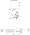
- an exit at the bottom of a water butt (2) is connected to the bottom of a rainfall measuring tube (13) via a water hose (14).
- a siphon (5) is in the wall of the rainfall measuring tube (13).
- the rainfall measuring tube (13) and a measuring device (6) are installed on a support bracket (9).
- the measuring device (6) is connected with a pressure sensor (12) which is installed in the bottom of the rainfall measuring tube (13) through a signal transmission lines (8), and it is also connected with a battery (11) through a power line (10).
- the whole apparatus is installed in an outer barrel (1).
- the water butt (2) is fixed on a support ring (3) and the support ring is in the outer barrel (1).
- the measuring device (6) is connected to an antenna (7).
- the measuring device (6) described includes a amplification and filtering circuit, an A/D conversion circuit, a single-chip microcomputer and a remote transmission module GSM or GPRS.
- One terminal of the amplification and filtering circuit is connected with the pressure sensor (12), and the other terminal is connected with the remote transmission module GSM or GPRS via the A/D conversion circuit and the single-chip microcomputer.
- the amplification and filtering circuit described uses differential structure or integrated instrument amplifier to constitute the amplification and filtering circuit.
- the input signal is the output voltage signal of the pressure sensor which is in proportional to the water level, and the output signal is the output voltage signal of the amplification and filtering circuit.
- the outermost portion of this apparatus is a protection barrel; the upper portion of the internal portion of the apparatus is a water butt (2), which collects natural rainfall.
- the rain flows through the water hose (14) into the rainfall measuring tube (13) below.
- the rainfall measuring tube (13) is a cylindrical hollow tube.
- the pressure sensor (12) can measure the water level of the rainfall measuring tube, while the water level is in proportion to the rainfall.
- the siphon phenomenon occurs, and the water inside the rainfall measuring tube (13) will be discharged through the siphon automatically.
- the measuring device will process the signal of the pressure sensor (12) by a series of steps, such as amplification, filtering, A/D conversion, value conversion, compensation calculations, encoding and remote transmission to realize the remote automatic rainfall measurement.
- the battery (11) is the power of the measuring device (6) and pressure sensor (12). Because of using the automatic drainage realized by siphon principle and rainfall measurement realized by pressure measurement, the power consumption of the apparatus is very low, and it's possible to use a battery for long-term supply.
- the key feature of the measuring device (6) is the self-compensation algorithm described later, which makes the precision of the device much higher than the existing tipping-bucket rain recorder and siphon rainfall recorder.
- the component of the measuring device is shown in FIG. 2 .
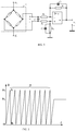
- the amplification and filtering circuit in FIG. 2 is an integrated operational amplifier of low power consumption, low temporal and thermal drift and low noise, which takes use of differential line structure.
- the circuit is shown in FIG. 3 . It can also use a variety of integrated instrument amplifier modules to constitute the amplification and filtering circuit.
- u i is the input voltage signal of the amplification and filtering circuit, which is also the output voltage signal of the pressure sensor that is in proportion to the water level.
- u o is the output voltage signal of the amplification and filtering circuit.
- A/D conversion circuit can be implemented with almost any kind of successive comparing parallel A/D converter or ⁇ - ⁇ type serial A/D converter.
- the present invention uses a 16 bit ⁇ - ⁇ type serial A/D converter (MAX1415 or MAX7705).
- Single chip microcomputer can be any product available. Considering of the power consumption, the present invention selects MSP430F series of TI. Specific model: MSP 430F135, or MSP 430F149.
- Remote transmission module GSM or GPRS can use productions of U.S. SIMCOM, German Siemens, or Taiwan BenQ, and the present invention uses sim300c of SIMCOM or BENQ M23 of BenQ.
- the method of rainfall measurement according to the present invention is as follows.
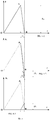
- FIG. 4-1 reflects the variation process of the water level of the rainfall measuring tube with rainfall.
- Segment O ⁇ A reflects the water level of the rainfall measuring tube rising by the rain.
- h N When the water level of the measuring tube reaches h N , siphon phenomenon occurs, and then the water level of the measuring tube falls.
- Segment A-B reflects this, and this process relies on siphon principle.
- point B In the cycle of water level of the rainfall measuring tube rising and falling, point B is the point O of the next cycle of water level, and the water level starts rising from the point B.
- FIG. 4-1 shows the variation process of the water level of the measuring tube with rainfall, and it is broken down into FIG. 4-2 and FIG. 4-3.
- FIG. 4-2 shows the variation process of the water level of the measuring tube without rainfall.
- FIG. 4-3 shows the changing of the water level caused by rainfall.
- Dotted line O-A-B in FIG. 4-2 and FIG. 4-3 is the actual changing curve of the water level shown in FIG. 4-1 .
- the actual changing curve of the water level without rainfall shown in FIG. 4-2 is the full line in t 1 ⁇ t ⁇ t' 2 .
- the chain line in t' 2 ⁇ t ⁇ t 2 is the extended line of the full line in t 1 ⁇ t ⁇ t' 2 .
- the chain line in t' 2 ⁇ t ⁇ t 2 will not exist in the siphon process without rainfall.
- the full line in t 1 ⁇ t ⁇ t' 2 and the chain line in t' 2 ⁇ t ⁇ t 2 are obtained by the subtraction between the curve of FIG. 4-1 and the curve of FIG. 4-3 . It can be drawn from FIG. 4-1, FIG. 4-2 and FIG. 4-3 that the falling rate of water level in the siphon process with rainfall (As shown in FIG. 4-1 , segment A-B) is slower than the rate without rainfall (As shown in FIG.
- h ( t ) represents the actual curve of the changing water level of the measuring tube with rainfall
- h 1 ( t ) represents the segment of the changing water level in the siphon process without rainfall and its extended line ( h 1 ( t ) include the full line and the chain line)
- h 2 ( t ) represents the changing of the water level caused by rainfall in t 1 ⁇ t ⁇ t 2 when siphon phenomenon occurs.
- h(t) in formula (1) is measured by the measuring system shown in FIG. 1 .
- the full line part of h 1 ( t ) is measured by the calibration test after the siphon and measuring tube are made and extended according to the slope of itself.
- the length of extended line is determined by t 2
- t 2 is determined by the rainfall rate.
- t 2 is big when the rainfall rate is big.
- t 2 is small when the rainfall rate is small.
- the time of every cycle of single measurement is unequal usually.
- h N is the maximum value of h(t), and the value of h N is determined by the structure of siphon and measuring tube.
- h N is a constant value in every single measurement.
- the actual curve of h ( t ) is not necessarily a straight line (usually a broken line), and h 2 ( t ) is not necessarily the translation of segment O-A of h ( t ).
- ⁇ h N ( j ) in formula (2) is the rainfall in t 1 ⁇ t ⁇ t 2 , i.e., in the siphon drainage process during a cycle of the j +1 th change of the water level of the measuring tube, and the cycle is showed in FIG. 4-1 .
- ⁇ h N equals to ⁇ h N ( j ), FIG. 4-3 .
- n means the loop showed in FIG.
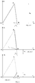
- the corresponding graphical representation of formula (3) is shown in FIG. 6 .
- the single cycle expressed by FIG. 6-1 is the same as the single cycle expressed by FIG. 4-1 .
- (t 20 , t 11 and t 21 in FIG. 6-1 are corresponding with 0, t 1 and t 2 in FIG. 4-1 Separately).
- h(t) in formula (3) is measured actually.
- h 1 ( t ) in t 1 (n+1) ⁇ t ⁇ t' 2(n+1) is the inherent siphon drainage line that has been predetermined
- h 1 ( t ) is an extended line of the inherent siphon drainage line.
- t 2(n+1) can be determined by the moment when the cycle reaches its bottom in FIG. 6-1 , and this can be realized by the corresponding programs at MCU in the measuring device.
Landscapes
- Life Sciences & Earth Sciences (AREA)
- Environmental & Geological Engineering (AREA)
- Hydrology & Water Resources (AREA)
- Engineering & Computer Science (AREA)
- Atmospheric Sciences (AREA)
- Biodiversity & Conservation Biology (AREA)
- Ecology (AREA)
- Environmental Sciences (AREA)
- Measurement Of Levels Of Liquids Or Fluent Solid Materials (AREA)
Description
- The present invention relates to rainfall measurement, and particularly to a method and apparatus for the remote siphon drainage type rainfall measurement with self-compensation function.
- Rainfall measurement is needed in the fields of meteorology, water conservation, geological disaster prevention, etc. For the remote rainfall measurement in the wild, considering the power consumption during drainage, the existing apparatus for remote automatic rainfall measurement uses a tipping bucket sensor, but its accuracy is relatively low, and the measurement error is typically ±4%. The existing apparatus for the siphon drainage type rainfall measurement relies on a paper-tape recording equipment with mechanical mechanism, which needs workers arrive at the scene to observe the recorded plot on the paper-tape to obtain the amount of rainfall, and its measurement error is ± 2%. The message on the paper can not be transmitted remotely. Therefore, there is a need for a method and apparatus for remote measurement, which not only meet the requirements of the low power consumption in the wild, but also realize high-accuracy survey of the rainfall.
- Chinese utility model
CN201021943Y discloses a combined tipping bucket and siphon drainage rain gauge. Another siphon drainage rain gauge is described inFR 2 713 784 A1 - The purpose of the present invention is to provide a method and an apparatus for the remote siphon drainage type rainfall measurement with self-compensation function, which can realize on-site survey with low power consumption, automatic data transmission with long distance, automatic drainage by making use of the siphon theory and the self-compensation function during siphon drainage.
- The technical solutions the invention takes to solve the technical problems are a method for remote siphon drainage type rainfall measurement with self-compensation as defined in
claim 1 and an apparatus for carrying out that method as defined inclaim 2. - The advantages of the present invention are as follows.
- The present invention can realize on-site survey with low power consumption, automatic data transmission with long distance, automatic drainage by making use of the siphon theory and the self-compensation function during siphon drainage. It will greatly improve the accuracy of the remote automatic rainfall measurement.
-
-
FIG. 1 is a schematic of a measuring apparatus according to the present invention; -
FIG. 2 is a block diagram of a measuring device according to the present invention; -
FIG. 3 is circuit diagram of the amplification and filtering circuit according to the present invention; -
FIG. 4 is an illustration of omitted rainfall ΔhN in the siphon process; -
FIG. 4-1 is a plot illustrating the siphon process with rainfall; -
FIG. 4-2 is a plot illustrating the siphon process without rainfall; -
FIG. 4-3 is a plot illustrating rainfall in the siphon process with rainfall; -
FIG. 5 is the cyclic O-A-B graph drawn on the coordinate paper by the existing siphon rainfall recorder; -
FIG. 6 is a plot that shows the n+1th cycle of the water level of the measuring tube rising and falling by siphon drainage; -
FIG. 6-1 is a plot that shows the n+1th cycle of the water level of the measuring tube rising and falling by siphon drainage with rainfall; -
FIG. 6-2 is a plot that shows the siphon process without rainfall; -
FIG. 6-3 is a plot that shows the rainfall in the siphon process with rainfall. - In the drawings: (1) - Outer barrel, (2) -Water butt, (3) - Support ring, (4) - The height of siphon, (5) - Siphon, (6) - Measuring device, (7) - Antenna, (8) - Signal transmission lines, (9) - Support bracket, (10) - Power line, (11) - Battery, (12) - Pressure sensor, (13) - Rainfall measuring tube, (14) - Water hose.
- The description below will be made to the embodiments of the present invention in conjunction with the annexed drawings .
- As shown in
FIG. 1 , an exit at the bottom of a water butt (2) is connected to the bottom of a rainfall measuring tube (13) via a water hose (14). A siphon (5) is in the wall of the rainfall measuring tube (13). The rainfall measuring tube (13) and a measuring device (6) are installed on a support bracket (9). The measuring device (6) is connected with a pressure sensor (12) which is installed in the bottom of the rainfall measuring tube (13) through a signal transmission lines (8), and it is also connected with a battery (11) through a power line (10). The whole apparatus is installed in an outer barrel (1). The water butt (2) is fixed on a support ring (3) and the support ring is in the outer barrel (1). The measuring device (6) is connected to an antenna (7). - As shown in
FIG. 2 andFIG. 3 , the measuring device (6) described includes a amplification and filtering circuit, an A/D conversion circuit, a single-chip microcomputer and a remote transmission module GSM or GPRS. One terminal of the amplification and filtering circuit is connected with the pressure sensor (12), and the other terminal is connected with the remote transmission module GSM or GPRS via the A/D conversion circuit and the single-chip microcomputer. - The amplification and filtering circuit described uses differential structure or integrated instrument amplifier to constitute the amplification and filtering circuit. The input signal is the output voltage signal of the pressure sensor which is in proportional to the water level, and the output signal is the output voltage signal of the amplification and filtering circuit.
- As shown in
FIG. 1 , the outermost portion of this apparatus is a protection barrel; the upper portion of the internal portion of the apparatus is a water butt (2), which collects natural rainfall. The rain flows through the water hose (14) into the rainfall measuring tube (13) below. The rainfall measuring tube (13) is a cylindrical hollow tube. In the bottom of rainfall measuring tube (13), there is a rainproof pressure sensor (12). According to the principle that the pressure of the bottom of the rainfall measuring tube is in proportion to the water level of the rainfall measuring tube, the pressure sensor (12) can measure the water level of the rainfall measuring tube, while the water level is in proportion to the rainfall. There is a siphon (5) in the wall of the rainfall measuring tube (13) which is used for the automatic water drainage of the rainfall measuring tube (13). According to the siphon principle, when the water level of the measuring tube reaches a certain height (The dashed line inFIG. 1 means the height of siphon (4)), the siphon phenomenon occurs, and the water inside the rainfall measuring tube (13) will be discharged through the siphon automatically. The measuring device will process the signal of the pressure sensor (12) by a series of steps, such as amplification, filtering, A/D conversion, value conversion, compensation calculations, encoding and remote transmission to realize the remote automatic rainfall measurement. The battery (11) is the power of the measuring device (6) and pressure sensor (12). Because of using the automatic drainage realized by siphon principle and rainfall measurement realized by pressure measurement, the power consumption of the apparatus is very low, and it's possible to use a battery for long-term supply. - The key feature of the measuring device (6) is the self-compensation algorithm described later, which makes the precision of the device much higher than the existing tipping-bucket rain recorder and siphon rainfall recorder. The component of the measuring device is shown in
FIG. 2 . - The amplification and filtering circuit in
FIG. 2 is an integrated operational amplifier of low power consumption, low temporal and thermal drift and low noise, which takes use of differential line structure. The circuit is shown inFIG. 3 . It can also use a variety of integrated instrument amplifier modules to constitute the amplification and filtering circuit. u i is the input voltage signal of the amplification and filtering circuit, which is also the output voltage signal of the pressure sensor that is in proportion to the water level. u o is the output voltage signal of the amplification and filtering circuit. - A/D conversion circuit can be implemented with almost any kind of successive comparing parallel A/D converter or Σ-Δ type serial A/D converter. In order to give consideration to speed, cost and power consumption, the present invention uses a 16 bit Σ -Δ type serial A/D converter (MAX1415 or MAX7705).
- Single chip microcomputer (MCU) can be any product available. Considering of the power consumption, the present invention selects MSP430F series of TI. Specific model: MSP 430F135, or MSP 430F149.
- Remote transmission module GSM or GPRS can use productions of U.S. SIMCOM, German Siemens, or Taiwan BenQ, and the present invention uses sim300c of SIMCOM or BENQ M23 of BenQ.
- The method of rainfall measurement according to the present invention is as follows.
- Drainage realized by siphon principle does not need energy, and this is a good way to reduce energy consumption for the automatic measurement in the wild. Assume that the rainfall speed is invariable,
FIG. 4-1 reflects the variation process of the water level of the rainfall measuring tube with rainfall. Segment O→A reflects the water level of the rainfall measuring tube rising by the rain. When the water level of the measuring tube reaches h N, siphon phenomenon occurs, and then the water level of the measuring tube falls. Segment A-B reflects this, and this process relies on siphon principle. In the cycle of water level of the rainfall measuring tube rising and falling, point B is the point O of the next cycle of water level, and the water level starts rising from the point B. The existing siphon rainfall recorder uses a set of mechanical structure to make the height of the nib changing with the water level of the measuring tube. After this, the cyclic curve O-A-B can be drawn on the coordinate paper (as shown inFIG. 5 ). After the rain stops, the meteorologist counts the amount of segment O-A on the coordinate paper (the amount of h N, n), then measures the height of the segment which does not reach point A in the last cycle (h x) (as shown inFIG. 5 ). h Σ = n·hN +hX. h Σ, the rainfall of this rainfall process. When the water level of the measuring tube reaches the height of h N (siphon height), the siphon phenomenon occurs, and the water level starts to fall (segment A-B, as shown inFIG. 4-1 ). As the rain does not stop, rainfall Δh N will be omitted in Δt=t 2 -t 1 (As shown inFIG. 4-1 ) if h N is used to calculate rainfall only. The value of Δh N is shown inFIG. 4-3 . Δh N is the full line in t 1 ≤t≤t2, and it is in parallel with segment O-A. Therefore, the total omitted rainfall of h Σ(h Σ = n·h N+h X) measured by the existing siphon rainfall recorder is Δh Σ(Δh Σ=n·Δh N). The actual rainfall should be h Σ+Δh Σ = n·h N+h X+ n·Δh N. - According to the analysis above, the present invention puts forward a compensation algorithm to eliminate errors in the siphon process.
FIG. 4-1 shows the variation process of the water level of the measuring tube with rainfall, and it is broken down intoFIG. 4-2 and FIG. 4-3. FIG. 4-2 shows the variation process of the water level of the measuring tube without rainfall.FIG. 4-3 shows the changing of the water level caused by rainfall. Dotted line O-A-B inFIG. 4-2 and FIG. 4-3 is the actual changing curve of the water level shown inFIG. 4-1 . The actual changing curve of the water level without rainfall shown inFIG. 4-2 is the full line in t 1≤t≤t'2. The chain line in t'2≤t≤t 2 is the extended line of the full line in t 1≤t≤t'2. The chain line in t'2≤t≤t 2 will not exist in the siphon process without rainfall. The full line in t1≤t≤t'2 and the chain line in t'2≤t≤t 2 are obtained by the subtraction between the curve ofFIG. 4-1 and the curve ofFIG. 4-3 . It can be drawn fromFIG. 4-1, FIG. 4-2 and FIG. 4-3 that the falling rate of water level in the siphon process with rainfall (As shown inFIG. 4-1 , segment A-B) is slower than the rate without rainfall (As shown inFIG. 4-2 , the full line in t 1 ≤t≤t'2 ), the reason is that there is rainfall in the former siphon process. To illustrate this, the rainfall rate in t 1 ≤t≤t2 and 0≤t≤t 1 will be assumed to be the same, and the curve ofFIG. 4-3 is in parallel with the segment O-A inFIG. 4-1 . It can be seen from the siphon principle that the curve of the falling water level in t 1≤t≤t'2 is a fixed line after the measurement tube and the siphon being made, and it won't change with rainfall. In actual measurement, the segment of the changing water level corresponding to the actual rainfall in t 1≤t≤t 2 (As shown inFIG. 4-3 ) will be obtained, after the actual curve of the changing water level of the measuring tube in the siphon process(As shown inFIG. 4-1 , segment A-B) minus the segment of the changing water level in the siphon process without rainfall and its extended line (As shown inFIG. 4-2 , the full line in t 1≤t≤t'2 and the chain line in t'2≤t≤-t2 ), so as to obtain Δh N. It should be noted that, as the actual rainfall rate is not constant, the segments O-A and A-B ofFIG. 4-1 are not linear in actual measurement. However, the actual segment of changing water level in the siphon process without rainfall is linear. So, the expression of compensation in actual measurement can be obtained fromFIG. 4 . h(t) represents the actual curve of the changing water level of the measuring tube with rainfall, h 1(t) represents the segment of the changing water level in the siphon process without rainfall and its extended line (h 1(t) include the full line and the chain line), h 2(t) represents the changing of the water level caused by rainfall in t1≤t≤t2 when siphon phenomenon occurs. The expression of rainfall with compensation in single measurement (0≤t≤t2 ) is:
- h(t) in formula (1) is measured by the measuring system shown in
FIG. 1 . The full line part of h 1(t) is measured by the calibration test after the siphon and measuring tube are made and extended according to the slope of itself. The length of extended line is determined by t 2 , and t 2 is determined by the rainfall rate. t 2 is big when the rainfall rate is big. t 2 is small when the rainfall rate is small. The time of every cycle of single measurement is unequal usually. h N is the maximum value of h(t), and the value of h N is determined by the structure of siphon and measuring tube. h N is a constant value in every single measurement. As the actual rainfall rate is changing, the actual curve of h(t) is not necessarily a straight line (usually a broken line), and h2 (t) is not necessarily the translation of segment O-A of h(t). - According to the formula upper, the rainfall at any time can be expressed as:

- Δh N (j) in formula (2) is the rainfall in t1≤t≤t2, i.e., in the siphon drainage process during a cycle of the j+1th change of the water level of the measuring tube, and the cycle is showed in
FIG. 4-1 . (Δh N equals to Δh N (j),FIG. 4-3 ). As the rainfall rate is not constant, each Δh N(j) is generally different, i.e., Δh N (j-1)≠Δh N (j)≠Δh N (j+1) and if i<0, then Δh N (i)=0. n, means the loop showed inFIG. 4-1 has completed n cycles, the value of n can be 0, 1, 2, ...... ; K is a scale factor for converting the water level of the measuring tube into the rainfall. According to the formula (1), h s(n+1)(t) is expressed as:
- The formula (3) expresses any cycle of the water level of the measuring tube rising and falling by siphon drainage in rainfall process. When n=0, the formula (3) expresses the first cycle. The corresponding graphical representation of formula (3) is shown in
FIG. 6 . When n=0, the single cycle expressed byFIG. 6-1 is the same as the single cycle expressed byFIG. 4-1 . (t20, t 11 and t 21 inFIG. 6-1 are corresponding with 0, t 1 and t 2 inFIG. 4-1 Separately). h(t) in formula (3) is measured actually. h 1(t) in t 1(n+1)≤t≤t' 2(n+1) is the inherent siphon drainage line that has been predetermined, while in t'2(n+1)≤t≤t2(n+1), h 1(t) is an extended line of the inherent siphon drainage line. t2(n+1) can be determined by the moment when the cycle reaches its bottom inFIG. 6-1 , and this can be realized by the corresponding programs at MCU in the measuring device. After obtaining t 2(n+1), the programs of the MCU will make the extended line of the inherent siphon drainage line, and then h 1(t) will be totally determined in t 1(n+1)≤t≤t 2(n+1). The result of formula (3) is substituted to the formula (2) to obtain the measured value of rainfall with compensation h rain(t).
Claims (4)
- A method for remote siphon drainage type rainfall measurement with self-compensation, characterized in comprising:
expressing the amount of rainfall at any time with self-compensation as: h N is a water level at which a siphon phenomenon occurs;Δh N (j) in formula (1) is the amount of rainfall in t 1(n+1) ≤t≤t 2(n+1) , i.e., in the siphon drainage process during a cycle of the j+1th change of a water level of a measuring tube;each Δh N (j) is generally different, i.e. Δh N (j-1) ≠ Δh N (j) ≠ Δh N (j+1) and if i<0, then Δh N (i)=0;n is an integer ≥ 0 which denotes that the loop of the change of the water level of the measuring tube has completed n cycles;K is a scale factor for converting the water level of the measuring tube into the amount of rainfall;h s(n+1)(t) is expressed as:
 h(t) is an actual water level measured by the measuring tube;h 1(t) in t 1(n+1)≤t≤t'2(n+1) is an inherent siphon drainage line, which is a known relationship that has been predetermined,h 1(t) in t'2(n+1)≤t≤t 2(n+1) is an extended line of the inherent siphon drainage line;t 2(n+1) is determined by the moment when the cycle of the water level of the measuring tube rising and falling by siphon drainage reaches its lowest point, and this is realized by corresponding programs at a single-chip microcomputer MCU in a measuring device ; after obtaining t 2(n+1), the programs of the MCU will make the extended line of the inherent siphon drainage line, and then h 1(t) will be totally determined in t 1(n+1)≤t≤t 2(n+1);substituting the result of formula (2) to formula (1) to obtain the measured value of the amount of rainfall with compensation h rain(t),
wherein Δh N is the change of the water level of the measuring tube during the actual siphon process with rainfall, minus the change of the water level in the siphon process without rainfall and its extended line, extended to the time point (B) where the actual siphon process with rainfall is completed. - An apparatus for carrying out the method according to claim 1, characterized in that:an exit at the bottom of a water butt (2) is connected to the bottom of a rainfall measuring tube (13) via a water hose (14);a siphon (5) is in the wall of the rainfall measuring tube (13);the rainfall measuring tube (13) and the measuring device (6) are installed on a support bracket (9);the measuring device (6) includes the single-chip microcomputer;the measuring device (6) is connected with a pressure sensor (12) installed in the bottom of the rainfall measuring tube (13) and a battery (11); andthe whole apparatus is installed in an outer barrel (1).
- The apparatus of claim 2, characterized in that the measuring device (6) further includes an amplification and filtering circuit, an A/D conversion circuit and a remote transmission module GSM or GPRS; one terminal of the amplification and filtering circuit is connected with the pressure sensor (12), and the other terminal is connected with the remote transmission module GSM or GPRS via the A/D conversion circuit and the single-chip microcomputer.
- The apparatus of claim 2, characterized in that the amplification and filtering circuit uses a differential structure or an integrated instrument amplifier to constitute the amplification and filtering circuit, and an input signal is an output voltage signal of the pressure sensor which is proportional to the water level, and the output signal is the output voltage signal of the amplification and filtering circuit.
Applications Claiming Priority (2)
| Application Number | Priority Date | Filing Date | Title |
|---|---|---|---|
| CN2009101541691A CN101718881B (en) | 2009-11-09 | 2009-11-09 | Self-compensation remote siphon drainage type measuring method and device for rainfall capacity |
| PCT/CN2010/076190 WO2011054235A1 (en) | 2009-11-09 | 2010-08-20 | Siphon drainage type rainfall remote-measurement device and method with self-compensation function |
Publications (3)
| Publication Number | Publication Date |
|---|---|
| EP2500751A1 EP2500751A1 (en) | 2012-09-19 |
| EP2500751A4 EP2500751A4 (en) | 2017-05-17 |
| EP2500751B1 true EP2500751B1 (en) | 2019-12-04 |
Family
ID=42433483
Family Applications (1)
| Application Number | Title | Priority Date | Filing Date |
|---|---|---|---|
| EP10827849.0A Active EP2500751B1 (en) | 2009-11-09 | 2010-08-20 | Siphon drainage type rainfall remote-measurement device and method with self-compensation function |
Country Status (4)
| Country | Link |
|---|---|
| US (1) | US9588253B2 (en) |
| EP (1) | EP2500751B1 (en) |
| CN (1) | CN101718881B (en) |
| WO (1) | WO2011054235A1 (en) |
Families Citing this family (16)
| Publication number | Priority date | Publication date | Assignee | Title |
|---|---|---|---|---|
| CN101718881B (en) | 2009-11-09 | 2011-01-05 | 中国计量学院 | Self-compensation remote siphon drainage type measuring method and device for rainfall capacity |
| ES2436693B1 (en) * | 2012-06-29 | 2014-08-22 | Geonica, S.A. | PLUVIOMETER WITH AUTOMATIC PRIMING SIPHONE |
| CN102866437B (en) * | 2012-10-23 | 2014-07-09 | 东北林业大学 | Rapid measuring method for water amount of rain container |
| CN103362202A (en) * | 2013-07-12 | 2013-10-23 | 浙江海河环境科技有限公司 | Automatic switching system for initial rainwater collection |
| CN103675952A (en) * | 2013-12-08 | 2014-03-26 | 无锡蚂蚁微威科技有限公司 | Rain gauge with curve neck |
| CN104748820A (en) * | 2015-03-17 | 2015-07-01 | 周庆华 | Automatic muddy water weighting instrument |
| CN104729883A (en) * | 2015-03-17 | 2015-06-24 | 周庆华 | Automatic runoff and sediment monitor water inlet siphon type regulating device |
| CN105068156A (en) * | 2015-09-15 | 2015-11-18 | 成都汉康信息产业有限公司 | Rainfall detector for geological disaster |
| CN106197546A (en) * | 2016-07-29 | 2016-12-07 | 南京工业职业技术学院 | A kind of automatic detection and the rainwater supervising device of report |
| CN109459804B (en) * | 2018-11-26 | 2023-08-15 | 南京信息工程大学 | a rain gauge |
| CN109343156B (en) * | 2018-12-10 | 2020-12-15 | 安徽沃特水务科技有限公司 | Rain-proof amount report missing remote measurement terminal machine |
| CN109444993B (en) * | 2018-12-10 | 2023-08-22 | 南京信息工程大学 | Ultrasonic rain gauge based on MSP single-chip microcomputer and rain measuring method |
| CN114488353B (en) * | 2022-01-05 | 2026-04-14 | 广州极飞科技股份有限公司 | Rainfall measuring method and device, storage medium and electronic equipment |
| CN114442201A (en) * | 2022-01-24 | 2022-05-06 | 张锦霞 | Intelligent rainfall measuring rain gauge |
| JP2025039192A (en) * | 2023-09-08 | 2025-03-21 | Tstジャパン株式会社 | Rain gauge and rainwater container for rain gauge |
| CN117824745B (en) * | 2023-12-25 | 2026-06-05 | 江苏凯伦建材股份有限公司 | A test device for a membrane-coated metal roof siphon drainage system |
Family Cites Families (18)
| Publication number | Priority date | Publication date | Assignee | Title |
|---|---|---|---|---|
| CN87210894U (en) * | 1987-07-22 | 1988-04-06 | 云南省西双版纳州水文站 | Siphoning rain monthly gange |
| US4836018A (en) * | 1988-10-17 | 1989-06-06 | Charles Dispenza | Rain gauge with improved syphon discharge |
| FR2663129B1 (en) * | 1990-06-12 | 1993-01-29 | Oneill Andre | RAINFALL TO INTERMEDIATE TANK. |
| FR2713784B1 (en) * | 1993-12-13 | 1997-06-06 | Michel Haug | Rain gauge with contacts and automatic emptying. |
| US6027639A (en) * | 1996-04-30 | 2000-02-22 | Stormwater Treatment Llc | Self-cleaning siphon-actuated radial flow filter basket |
| US6649048B2 (en) * | 2001-11-20 | 2003-11-18 | Stormwater Management | Filter cartridge with regulated surface cleaning mechanism |
| CN2819241Y (en) * | 2005-06-07 | 2006-09-20 | 河海大学 | Rainfall metering controller |
| US8512555B1 (en) * | 2006-08-23 | 2013-08-20 | Contech Engineered Solutions LLC | Filter assembly, system and method |
| US8104499B2 (en) * | 2007-01-29 | 2012-01-31 | Abdul Rashid | Precision siphon operated septic field dosing system with filtration and backwash |
| DE102007004705A1 (en) * | 2007-01-31 | 2008-08-07 | Elsner Elektronik Gmbh | Rainfall gauge |
| KR100872502B1 (en) * | 2007-02-06 | 2008-12-10 | 대한민국 | Weight and Drain Cross Precipitation |
| CN201021943Y (en) * | 2007-02-12 | 2008-02-13 | 河海大学 | A digital rain gauge with siphon correction |
| US8110099B2 (en) * | 2007-05-09 | 2012-02-07 | Contech Stormwater Solutions Inc. | Stormwater filter assembly |
| CN100595607C (en) * | 2007-05-16 | 2010-03-24 | 张敏 | Electronic Siphon Rain Gauge |
| CN201449459U (en) * | 2009-06-23 | 2010-05-05 | 南京信息工程大学 | a rain sensor |
| CN101718881B (en) * | 2009-11-09 | 2011-01-05 | 中国计量学院 | Self-compensation remote siphon drainage type measuring method and device for rainfall capacity |
| US8662328B2 (en) * | 2010-09-23 | 2014-03-04 | 9224-9838 Quebec Inc. | Interconnecting container system |
| US8820346B2 (en) * | 2012-02-23 | 2014-09-02 | Thomas L. CORBETT | Self-actuating drainage device and method of operation |
-
2009
- 2009-11-09 CN CN2009101541691A patent/CN101718881B/en active Active
-
2010
- 2010-08-20 EP EP10827849.0A patent/EP2500751B1/en active Active
- 2010-08-20 WO PCT/CN2010/076190 patent/WO2011054235A1/en not_active Ceased
-
2012
- 2012-04-27 US US13/457,559 patent/US9588253B2/en active Active
Non-Patent Citations (1)
| Title |
|---|
| None * |
Also Published As
| Publication number | Publication date |
|---|---|
| CN101718881B (en) | 2011-01-05 |
| WO2011054235A1 (en) | 2011-05-12 |
| US9588253B2 (en) | 2017-03-07 |
| CN101718881A (en) | 2010-06-02 |
| EP2500751A4 (en) | 2017-05-17 |
| EP2500751A1 (en) | 2012-09-19 |
| US20120253675A1 (en) | 2012-10-04 |
Similar Documents
| Publication | Publication Date | Title |
|---|---|---|
| US9588253B2 (en) | Method and apparatus for remote siphon drainage type rainfall measurement with self-compensation function | |
| CN101451903B (en) | A device and method for testing the deflection of a semi-closed single connected pipe bridge | |
| CN205175854U (en) | Automatic monitoring device of runoff and silt | |
| US4965756A (en) | Method and apparatus for calibration of electronic gas meters | |
| CN203310718U (en) | Device for measuring density and liquid level height of engine fuel oil | |
| CN101162165A (en) | Low gas content gas-liquid two-phase flow measuring apparatus based on capacitance sensor and standard venturi tube | |
| CN101871266B (en) | Automatic acquisition system for concrete cooling water data | |
| US4953386A (en) | Method and apparatus for proving electronic gas meters | |
| CN103345004B (en) | Adopt rainfall monitoring network and the method for fiber grating siphon rainfall recorder | |
| CN103528791B (en) | Bottom-sitting type round-the-clock bed load sediment real-time monitor and measuring method thereof | |
| CN204613432U (en) | A kind of Novel siphon rain gauge device | |
| CN112067841A (en) | Device and method for measuring flow velocity of open channel by liquid level time difference | |
| CN102435230A (en) | Triangular Weir Slope Area Runoff Flow Measurement System | |
| RU176710U1 (en) | DEVICE FOR MEASURING PHYSICAL PARAMETERS IN A WELL | |
| CN111173496A (en) | Oil well liquid production amount metering device and method | |
| CN113945999A (en) | Analog detection device and metering method for optical rainfall sensor | |
| CN108387277A (en) | Irrigated area integrated water level flow wireless measurement method and device | |
| CN108332712A (en) | Differential Settlement Profiler meter and Settlement Profiler monitoring method | |
| CN101586979B (en) | A constant-flow bubble type automatic water level measurement method | |
| CN101586981A (en) | Constant-flow bubble type automatic water level measurement device with micro power consumption | |
| US4926678A (en) | Method and apparatus for proving electronic gas meters at low flow rates | |
| CN205785187U (en) | A kind of vertical deformation detection device | |
| CN105259209B (en) | L NG evaporation rate measuring system and calculating method | |
| CN203364917U (en) | High-precision water level gauge and osmometer | |
| CN100432705C (en) | Capacitance rainfall metering method and device by drop method |
Legal Events
| Date | Code | Title | Description |
|---|---|---|---|
| PUAI | Public reference made under article 153(3) epc to a published international application that has entered the european phase |
Free format text: ORIGINAL CODE: 0009012 |
|
| 17P | Request for examination filed |
Effective date: 20120425 |
|
| AK | Designated contracting states |
Kind code of ref document: A1 Designated state(s): AL AT BE BG CH CY CZ DE DK EE ES FI FR GB GR HR HU IE IS IT LI LT LU LV MC MK MT NL NO PL PT RO SE SI SK SM TR |
|
| DAX | Request for extension of the european patent (deleted) | ||
| RA4 | Supplementary search report drawn up and despatched (corrected) |
Effective date: 20170418 |
|
| RIC1 | Information provided on ipc code assigned before grant |
Ipc: G01W 1/14 20060101AFI20170410BHEP |
|
| STAA | Information on the status of an ep patent application or granted ep patent |
Free format text: STATUS: EXAMINATION IS IN PROGRESS |
|
| 17Q | First examination report despatched |
Effective date: 20180423 |
|
| GRAP | Despatch of communication of intention to grant a patent |
Free format text: ORIGINAL CODE: EPIDOSNIGR1 |
|
| STAA | Information on the status of an ep patent application or granted ep patent |
Free format text: STATUS: GRANT OF PATENT IS INTENDED |
|
| INTG | Intention to grant announced |
Effective date: 20190710 |
|
| GRAS | Grant fee paid |
Free format text: ORIGINAL CODE: EPIDOSNIGR3 |
|
| GRAA | (expected) grant |
Free format text: ORIGINAL CODE: 0009210 |
|
| STAA | Information on the status of an ep patent application or granted ep patent |
Free format text: STATUS: THE PATENT HAS BEEN GRANTED |
|
| AK | Designated contracting states |
Kind code of ref document: B1 Designated state(s): AL AT BE BG CH CY CZ DE DK EE ES FI FR GB GR HR HU IE IS IT LI LT LU LV MC MK MT NL NO PL PT RO SE SI SK SM TR |
|
| REG | Reference to a national code |
Ref country code: GB Ref legal event code: FG4D |
|
| REG | Reference to a national code |
Ref country code: CH Ref legal event code: EP |
|
| REG | Reference to a national code |
Ref country code: AT Ref legal event code: REF Ref document number: 1210087 Country of ref document: AT Kind code of ref document: T Effective date: 20191215 |
|
| REG | Reference to a national code |
Ref country code: DE Ref legal event code: R096 Ref document number: 602010062281 Country of ref document: DE |
|
| REG | Reference to a national code |
Ref country code: IE Ref legal event code: FG4D |
|
| REG | Reference to a national code |
Ref country code: NL Ref legal event code: MP Effective date: 20191204 |
|
| REG | Reference to a national code |
Ref country code: LT Ref legal event code: MG4D |
|
| PG25 | Lapsed in a contracting state [announced via postgrant information from national office to epo] |
Ref country code: GR Free format text: LAPSE BECAUSE OF FAILURE TO SUBMIT A TRANSLATION OF THE DESCRIPTION OR TO PAY THE FEE WITHIN THE PRESCRIBED TIME-LIMIT Effective date: 20200305 Ref country code: NO Free format text: LAPSE BECAUSE OF FAILURE TO SUBMIT A TRANSLATION OF THE DESCRIPTION OR TO PAY THE FEE WITHIN THE PRESCRIBED TIME-LIMIT Effective date: 20200304 Ref country code: LV Free format text: LAPSE BECAUSE OF FAILURE TO SUBMIT A TRANSLATION OF THE DESCRIPTION OR TO PAY THE FEE WITHIN THE PRESCRIBED TIME-LIMIT Effective date: 20191204 Ref country code: SE Free format text: LAPSE BECAUSE OF FAILURE TO SUBMIT A TRANSLATION OF THE DESCRIPTION OR TO PAY THE FEE WITHIN THE PRESCRIBED TIME-LIMIT Effective date: 20191204 Ref country code: FI Free format text: LAPSE BECAUSE OF FAILURE TO SUBMIT A TRANSLATION OF THE DESCRIPTION OR TO PAY THE FEE WITHIN THE PRESCRIBED TIME-LIMIT Effective date: 20191204 Ref country code: BG Free format text: LAPSE BECAUSE OF FAILURE TO SUBMIT A TRANSLATION OF THE DESCRIPTION OR TO PAY THE FEE WITHIN THE PRESCRIBED TIME-LIMIT Effective date: 20200304 Ref country code: ES Free format text: LAPSE BECAUSE OF FAILURE TO SUBMIT A TRANSLATION OF THE DESCRIPTION OR TO PAY THE FEE WITHIN THE PRESCRIBED TIME-LIMIT Effective date: 20191204 Ref country code: LT Free format text: LAPSE BECAUSE OF FAILURE TO SUBMIT A TRANSLATION OF THE DESCRIPTION OR TO PAY THE FEE WITHIN THE PRESCRIBED TIME-LIMIT Effective date: 20191204 |
|
| PG25 | Lapsed in a contracting state [announced via postgrant information from national office to epo] |
Ref country code: HR Free format text: LAPSE BECAUSE OF FAILURE TO SUBMIT A TRANSLATION OF THE DESCRIPTION OR TO PAY THE FEE WITHIN THE PRESCRIBED TIME-LIMIT Effective date: 20191204 |
|
| PG25 | Lapsed in a contracting state [announced via postgrant information from national office to epo] |
Ref country code: AL Free format text: LAPSE BECAUSE OF FAILURE TO SUBMIT A TRANSLATION OF THE DESCRIPTION OR TO PAY THE FEE WITHIN THE PRESCRIBED TIME-LIMIT Effective date: 20191204 |
|
| PG25 | Lapsed in a contracting state [announced via postgrant information from national office to epo] |
Ref country code: PT Free format text: LAPSE BECAUSE OF FAILURE TO SUBMIT A TRANSLATION OF THE DESCRIPTION OR TO PAY THE FEE WITHIN THE PRESCRIBED TIME-LIMIT Effective date: 20200429 Ref country code: CZ Free format text: LAPSE BECAUSE OF FAILURE TO SUBMIT A TRANSLATION OF THE DESCRIPTION OR TO PAY THE FEE WITHIN THE PRESCRIBED TIME-LIMIT Effective date: 20191204 Ref country code: NL Free format text: LAPSE BECAUSE OF FAILURE TO SUBMIT A TRANSLATION OF THE DESCRIPTION OR TO PAY THE FEE WITHIN THE PRESCRIBED TIME-LIMIT Effective date: 20191204 Ref country code: RO Free format text: LAPSE BECAUSE OF FAILURE TO SUBMIT A TRANSLATION OF THE DESCRIPTION OR TO PAY THE FEE WITHIN THE PRESCRIBED TIME-LIMIT Effective date: 20191204 Ref country code: EE Free format text: LAPSE BECAUSE OF FAILURE TO SUBMIT A TRANSLATION OF THE DESCRIPTION OR TO PAY THE FEE WITHIN THE PRESCRIBED TIME-LIMIT Effective date: 20191204 |
|
| PG25 | Lapsed in a contracting state [announced via postgrant information from national office to epo] |
Ref country code: SM Free format text: LAPSE BECAUSE OF FAILURE TO SUBMIT A TRANSLATION OF THE DESCRIPTION OR TO PAY THE FEE WITHIN THE PRESCRIBED TIME-LIMIT Effective date: 20191204 Ref country code: SK Free format text: LAPSE BECAUSE OF FAILURE TO SUBMIT A TRANSLATION OF THE DESCRIPTION OR TO PAY THE FEE WITHIN THE PRESCRIBED TIME-LIMIT Effective date: 20191204 Ref country code: IS Free format text: LAPSE BECAUSE OF FAILURE TO SUBMIT A TRANSLATION OF THE DESCRIPTION OR TO PAY THE FEE WITHIN THE PRESCRIBED TIME-LIMIT Effective date: 20200404 |
|
| REG | Reference to a national code |
Ref country code: DE Ref legal event code: R097 Ref document number: 602010062281 Country of ref document: DE |
|
| REG | Reference to a national code |
Ref country code: AT Ref legal event code: MK05 Ref document number: 1210087 Country of ref document: AT Kind code of ref document: T Effective date: 20191204 |
|
| PLBE | No opposition filed within time limit |
Free format text: ORIGINAL CODE: 0009261 |
|
| STAA | Information on the status of an ep patent application or granted ep patent |
Free format text: STATUS: NO OPPOSITION FILED WITHIN TIME LIMIT |
|
| PG25 | Lapsed in a contracting state [announced via postgrant information from national office to epo] |
Ref country code: DK Free format text: LAPSE BECAUSE OF FAILURE TO SUBMIT A TRANSLATION OF THE DESCRIPTION OR TO PAY THE FEE WITHIN THE PRESCRIBED TIME-LIMIT Effective date: 20191204 |
|
| 26N | No opposition filed |
Effective date: 20200907 |
|
| PG25 | Lapsed in a contracting state [announced via postgrant information from national office to epo] |
Ref country code: AT Free format text: LAPSE BECAUSE OF FAILURE TO SUBMIT A TRANSLATION OF THE DESCRIPTION OR TO PAY THE FEE WITHIN THE PRESCRIBED TIME-LIMIT Effective date: 20191204 Ref country code: SI Free format text: LAPSE BECAUSE OF FAILURE TO SUBMIT A TRANSLATION OF THE DESCRIPTION OR TO PAY THE FEE WITHIN THE PRESCRIBED TIME-LIMIT Effective date: 20191204 Ref country code: PL Free format text: LAPSE BECAUSE OF FAILURE TO SUBMIT A TRANSLATION OF THE DESCRIPTION OR TO PAY THE FEE WITHIN THE PRESCRIBED TIME-LIMIT Effective date: 20191204 |
|
| PG25 | Lapsed in a contracting state [announced via postgrant information from national office to epo] |
Ref country code: IT Free format text: LAPSE BECAUSE OF FAILURE TO SUBMIT A TRANSLATION OF THE DESCRIPTION OR TO PAY THE FEE WITHIN THE PRESCRIBED TIME-LIMIT Effective date: 20191204 |
|
| PG25 | Lapsed in a contracting state [announced via postgrant information from national office to epo] |
Ref country code: MC Free format text: LAPSE BECAUSE OF FAILURE TO SUBMIT A TRANSLATION OF THE DESCRIPTION OR TO PAY THE FEE WITHIN THE PRESCRIBED TIME-LIMIT Effective date: 20191204 |
|
| REG | Reference to a national code |
Ref country code: CH Ref legal event code: PL |
|
| PG25 | Lapsed in a contracting state [announced via postgrant information from national office to epo] |
Ref country code: LU Free format text: LAPSE BECAUSE OF NON-PAYMENT OF DUE FEES Effective date: 20200820 Ref country code: LI Free format text: LAPSE BECAUSE OF NON-PAYMENT OF DUE FEES Effective date: 20200831 Ref country code: CH Free format text: LAPSE BECAUSE OF NON-PAYMENT OF DUE FEES Effective date: 20200831 |
|
| REG | Reference to a national code |
Ref country code: BE Ref legal event code: MM Effective date: 20200831 |
|
| PG25 | Lapsed in a contracting state [announced via postgrant information from national office to epo] |
Ref country code: IE Free format text: LAPSE BECAUSE OF NON-PAYMENT OF DUE FEES Effective date: 20200820 Ref country code: BE Free format text: LAPSE BECAUSE OF NON-PAYMENT OF DUE FEES Effective date: 20200831 |
|
| PG25 | Lapsed in a contracting state [announced via postgrant information from national office to epo] |
Ref country code: TR Free format text: LAPSE BECAUSE OF FAILURE TO SUBMIT A TRANSLATION OF THE DESCRIPTION OR TO PAY THE FEE WITHIN THE PRESCRIBED TIME-LIMIT Effective date: 20191204 Ref country code: MT Free format text: LAPSE BECAUSE OF FAILURE TO SUBMIT A TRANSLATION OF THE DESCRIPTION OR TO PAY THE FEE WITHIN THE PRESCRIBED TIME-LIMIT Effective date: 20191204 Ref country code: CY Free format text: LAPSE BECAUSE OF FAILURE TO SUBMIT A TRANSLATION OF THE DESCRIPTION OR TO PAY THE FEE WITHIN THE PRESCRIBED TIME-LIMIT Effective date: 20191204 |
|
| PG25 | Lapsed in a contracting state [announced via postgrant information from national office to epo] |
Ref country code: MK Free format text: LAPSE BECAUSE OF FAILURE TO SUBMIT A TRANSLATION OF THE DESCRIPTION OR TO PAY THE FEE WITHIN THE PRESCRIBED TIME-LIMIT Effective date: 20191204 |
|
| PGFP | Annual fee paid to national office [announced via postgrant information from national office to epo] |
Ref country code: GB Payment date: 20220825 Year of fee payment: 13 Ref country code: DE Payment date: 20220824 Year of fee payment: 13 |
|
| PGFP | Annual fee paid to national office [announced via postgrant information from national office to epo] |
Ref country code: FR Payment date: 20220823 Year of fee payment: 13 |
|
| REG | Reference to a national code |
Ref country code: DE Ref legal event code: R119 Ref document number: 602010062281 Country of ref document: DE |
|
| GBPC | Gb: european patent ceased through non-payment of renewal fee |
Effective date: 20230820 |
|
| PG25 | Lapsed in a contracting state [announced via postgrant information from national office to epo] |
Ref country code: GB Free format text: LAPSE BECAUSE OF NON-PAYMENT OF DUE FEES Effective date: 20230820 |
|
| PG25 | Lapsed in a contracting state [announced via postgrant information from national office to epo] |
Ref country code: GB Free format text: LAPSE BECAUSE OF NON-PAYMENT OF DUE FEES Effective date: 20230820 Ref country code: FR Free format text: LAPSE BECAUSE OF NON-PAYMENT OF DUE FEES Effective date: 20230831 Ref country code: DE Free format text: LAPSE BECAUSE OF NON-PAYMENT OF DUE FEES Effective date: 20240301 |