EP2500745A2 - Alignment method and system for radar of vehicle - Google Patents
Alignment method and system for radar of vehicle Download PDFInfo
- Publication number
- EP2500745A2 EP2500745A2 EP11180492A EP11180492A EP2500745A2 EP 2500745 A2 EP2500745 A2 EP 2500745A2 EP 11180492 A EP11180492 A EP 11180492A EP 11180492 A EP11180492 A EP 11180492A EP 2500745 A2 EP2500745 A2 EP 2500745A2
- Authority
- EP
- European Patent Office
- Prior art keywords
- radar
- vertical
- slope
- horizontal
- deviation angle
- Prior art date
- Legal status (The legal status is an assumption and is not a legal conclusion. Google has not performed a legal analysis and makes no representation as to the accuracy of the status listed.)
- Withdrawn
Links
Images


Classifications
-
- G—PHYSICS
- G01—MEASURING; TESTING
- G01S—RADIO DIRECTION-FINDING; RADIO NAVIGATION; DETERMINING DISTANCE OR VELOCITY BY USE OF RADIO WAVES; LOCATING OR PRESENCE-DETECTING BY USE OF THE REFLECTION OR RERADIATION OF RADIO WAVES; ANALOGOUS ARRANGEMENTS USING OTHER WAVES
- G01S13/00—Systems using the reflection or reradiation of radio waves, e.g. radar systems; Analogous systems using reflection or reradiation of waves whose nature or wavelength is irrelevant or unspecified
- G01S13/88—Radar or analogous systems specially adapted for specific applications
- G01S13/93—Radar or analogous systems specially adapted for specific applications for anti-collision purposes
- G01S13/931—Radar or analogous systems specially adapted for specific applications for anti-collision purposes of land vehicles
-
- G—PHYSICS
- G01—MEASURING; TESTING
- G01S—RADIO DIRECTION-FINDING; RADIO NAVIGATION; DETERMINING DISTANCE OR VELOCITY BY USE OF RADIO WAVES; LOCATING OR PRESENCE-DETECTING BY USE OF THE REFLECTION OR RERADIATION OF RADIO WAVES; ANALOGOUS ARRANGEMENTS USING OTHER WAVES
- G01S7/00—Details of systems according to groups G01S13/00, G01S15/00, G01S17/00
- G01S7/02—Details of systems according to groups G01S13/00, G01S15/00, G01S17/00 of systems according to group G01S13/00
- G01S7/40—Means for monitoring or calibrating
- G01S7/4004—Means for monitoring or calibrating of parts of a radar system
- G01S7/4026—Antenna boresight
-
- G—PHYSICS
- G01—MEASURING; TESTING
- G01S—RADIO DIRECTION-FINDING; RADIO NAVIGATION; DETERMINING DISTANCE OR VELOCITY BY USE OF RADIO WAVES; LOCATING OR PRESENCE-DETECTING BY USE OF THE REFLECTION OR RERADIATION OF RADIO WAVES; ANALOGOUS ARRANGEMENTS USING OTHER WAVES
- G01S7/00—Details of systems according to groups G01S13/00, G01S15/00, G01S17/00
- G01S7/02—Details of systems according to groups G01S13/00, G01S15/00, G01S17/00 of systems according to group G01S13/00
- G01S7/40—Means for monitoring or calibrating
- G01S7/4052—Means for monitoring or calibrating by simulation of echoes
-
- G—PHYSICS
- G01—MEASURING; TESTING
- G01S—RADIO DIRECTION-FINDING; RADIO NAVIGATION; DETERMINING DISTANCE OR VELOCITY BY USE OF RADIO WAVES; LOCATING OR PRESENCE-DETECTING BY USE OF THE REFLECTION OR RERADIATION OF RADIO WAVES; ANALOGOUS ARRANGEMENTS USING OTHER WAVES
- G01S13/00—Systems using the reflection or reradiation of radio waves, e.g. radar systems; Analogous systems using reflection or reradiation of waves whose nature or wavelength is irrelevant or unspecified
- G01S13/02—Systems using reflection of radio waves, e.g. primary radar systems; Analogous systems
- G01S13/06—Systems determining position data of a target
- G01S13/08—Systems for measuring distance only
- G01S13/32—Systems for measuring distance only using transmission of continuous waves, whether amplitude-, frequency-, or phase-modulated, or unmodulated
- G01S13/34—Systems for measuring distance only using transmission of continuous waves, whether amplitude-, frequency-, or phase-modulated, or unmodulated using transmission of continuous, frequency-modulated waves while heterodyning the received signal, or a signal derived therefrom, with a locally-generated signal related to the contemporaneously transmitted signal
-
- G—PHYSICS
- G01—MEASURING; TESTING
- G01S—RADIO DIRECTION-FINDING; RADIO NAVIGATION; DETERMINING DISTANCE OR VELOCITY BY USE OF RADIO WAVES; LOCATING OR PRESENCE-DETECTING BY USE OF THE REFLECTION OR RERADIATION OF RADIO WAVES; ANALOGOUS ARRANGEMENTS USING OTHER WAVES
- G01S13/00—Systems using the reflection or reradiation of radio waves, e.g. radar systems; Analogous systems using reflection or reradiation of waves whose nature or wavelength is irrelevant or unspecified
- G01S13/02—Systems using reflection of radio waves, e.g. primary radar systems; Analogous systems
- G01S13/06—Systems determining position data of a target
- G01S13/08—Systems for measuring distance only
- G01S13/32—Systems for measuring distance only using transmission of continuous waves, whether amplitude-, frequency-, or phase-modulated, or unmodulated
- G01S13/36—Systems for measuring distance only using transmission of continuous waves, whether amplitude-, frequency-, or phase-modulated, or unmodulated with phase comparison between the received signal and the contemporaneously transmitted signal
- G01S13/40—Systems for measuring distance only using transmission of continuous waves, whether amplitude-, frequency-, or phase-modulated, or unmodulated with phase comparison between the received signal and the contemporaneously transmitted signal wherein the frequency of transmitted signal is adjusted to give a predetermined phase relationship
-
- G—PHYSICS
- G01—MEASURING; TESTING
- G01S—RADIO DIRECTION-FINDING; RADIO NAVIGATION; DETERMINING DISTANCE OR VELOCITY BY USE OF RADIO WAVES; LOCATING OR PRESENCE-DETECTING BY USE OF THE REFLECTION OR RERADIATION OF RADIO WAVES; ANALOGOUS ARRANGEMENTS USING OTHER WAVES
- G01S13/00—Systems using the reflection or reradiation of radio waves, e.g. radar systems; Analogous systems using reflection or reradiation of waves whose nature or wavelength is irrelevant or unspecified
- G01S13/88—Radar or analogous systems specially adapted for specific applications
- G01S13/93—Radar or analogous systems specially adapted for specific applications for anti-collision purposes
- G01S13/931—Radar or analogous systems specially adapted for specific applications for anti-collision purposes of land vehicles
- G01S2013/9321—Velocity regulation, e.g. cruise control
-
- G—PHYSICS
- G01—MEASURING; TESTING
- G01S—RADIO DIRECTION-FINDING; RADIO NAVIGATION; DETERMINING DISTANCE OR VELOCITY BY USE OF RADIO WAVES; LOCATING OR PRESENCE-DETECTING BY USE OF THE REFLECTION OR RERADIATION OF RADIO WAVES; ANALOGOUS ARRANGEMENTS USING OTHER WAVES
- G01S13/00—Systems using the reflection or reradiation of radio waves, e.g. radar systems; Analogous systems using reflection or reradiation of waves whose nature or wavelength is irrelevant or unspecified
- G01S13/88—Radar or analogous systems specially adapted for specific applications
- G01S13/93—Radar or analogous systems specially adapted for specific applications for anti-collision purposes
- G01S13/931—Radar or analogous systems specially adapted for specific applications for anti-collision purposes of land vehicles
- G01S2013/9327—Sensor installation details
- G01S2013/93271—Sensor installation details in the front of the vehicles
-
- G—PHYSICS
- G01—MEASURING; TESTING
- G01S—RADIO DIRECTION-FINDING; RADIO NAVIGATION; DETERMINING DISTANCE OR VELOCITY BY USE OF RADIO WAVES; LOCATING OR PRESENCE-DETECTING BY USE OF THE REFLECTION OR RERADIATION OF RADIO WAVES; ANALOGOUS ARRANGEMENTS USING OTHER WAVES
- G01S7/00—Details of systems according to groups G01S13/00, G01S15/00, G01S17/00
- G01S7/02—Details of systems according to groups G01S13/00, G01S15/00, G01S17/00 of systems according to group G01S13/00
- G01S7/40—Means for monitoring or calibrating
- G01S7/4004—Means for monitoring or calibrating of parts of a radar system
- G01S7/4026—Antenna boresight
- G01S7/403—Antenna boresight in azimuth, i.e. in the horizontal plane
-
- G—PHYSICS
- G01—MEASURING; TESTING
- G01S—RADIO DIRECTION-FINDING; RADIO NAVIGATION; DETERMINING DISTANCE OR VELOCITY BY USE OF RADIO WAVES; LOCATING OR PRESENCE-DETECTING BY USE OF THE REFLECTION OR RERADIATION OF RADIO WAVES; ANALOGOUS ARRANGEMENTS USING OTHER WAVES
- G01S7/00—Details of systems according to groups G01S13/00, G01S15/00, G01S17/00
- G01S7/02—Details of systems according to groups G01S13/00, G01S15/00, G01S17/00 of systems according to group G01S13/00
- G01S7/40—Means for monitoring or calibrating
- G01S7/4004—Means for monitoring or calibrating of parts of a radar system
- G01S7/4026—Antenna boresight
- G01S7/4034—Antenna boresight in elevation, i.e. in the vertical plane
-
- G—PHYSICS
- G01—MEASURING; TESTING
- G01S—RADIO DIRECTION-FINDING; RADIO NAVIGATION; DETERMINING DISTANCE OR VELOCITY BY USE OF RADIO WAVES; LOCATING OR PRESENCE-DETECTING BY USE OF THE REFLECTION OR RERADIATION OF RADIO WAVES; ANALOGOUS ARRANGEMENTS USING OTHER WAVES
- G01S7/00—Details of systems according to groups G01S13/00, G01S15/00, G01S17/00
- G01S7/02—Details of systems according to groups G01S13/00, G01S15/00, G01S17/00 of systems according to group G01S13/00
- G01S7/40—Means for monitoring or calibrating
- G01S7/4052—Means for monitoring or calibrating by simulation of echoes
- G01S7/4082—Means for monitoring or calibrating by simulation of echoes using externally generated reference signals, e.g. via remote reflector or transponder
- G01S7/4091—Means for monitoring or calibrating by simulation of echoes using externally generated reference signals, e.g. via remote reflector or transponder during normal radar operation
Definitions
- Exemplary embodiments of the present invention relate to an alignment method and system for a radar of a vehicle, and more particularly, to an alignment method and system for a radar of a vehicle, which can automatically detect a vertical or horizontal misalignment of a radar mounted to a vehicle.
- an adaptive cruise control (ACC) system of a vehicle is adapted to automatically control a throttle valve, a brake, a transmission, etc. of the vehicle based on a position of and a distance to a preceding vehicle that are detected from a radar mounted to a front part of the vehicle, to thereby appropriately perform acceleration and deceleration and maintain an appropriate distance to the preceding vehicle.
- ACC adaptive cruise control
- the radar is mounted to a front end module of the vehicle and detect a position of and a distance to a preceding vehicle, alignment for the directionality of the radar and analysis for a coordinate value are regarded very important in adaptive cruise control.
- a problem is caused in that, when a directionality issue of the radar mounted to the vehicle occurs and in particular misalignment of the radar occurs in a horizontal or vertical direction with respect to the ground, it is difficult to detect automatically and effectively the misalignment and alarm a driver. Accordingly, in the conventional art, even in the case where erroneous travel information for the preceding vehicle is provided due to the misalignment of the radar in the horizontal or vertical direction, it is impossible for a driver to verify whether the information is correct or not, and thus the likelihood of an accident during travel cannot help but increase.
- Embodiments of the present invention relate to an alignment method and system for a radar of a vehicle, which can automatically detect a vertical or horizontal misalignment of a radar mounted to a vehicle and can alarm a driver or automatically correct the misalignment.
- a vertical alignment method for a radar of a vehicle including the steps of: radiating radio wave to a forward ground by a radar which is installed on the vehicle; receiving reflected wave which is reflected from the ground; and determining whether or not a vertical misalignment of the radar occurs, based on the reflected wave.
- the step of determining whether or not a vertical misalignment of the radar occurs may be implemented based on a frequency spectrum of the reflected wave.
- the step of determining whether or not a vertical misalignment of the radar occurs may include the steps of: calculating a vertical deviation angle of the radar based on the frequency spectrum of the reflected wave; and checking whether or not the vertical deviation angle is larger than a predetermined threshold value.
- the vertical deviation angle may be determined by a distance between the radar and the forward ground that is obtained by the frequency spectrum of the reflected wave.
- the method may further include the step of alarming a driver in the case where it is determined that the vertical misalignment occurs.
- the method may further include the step of alarming a driver and deactivating the radar in the case where it is determined that the vertical misalignment occurs.
- the method may further include the step of compensating for the vertical deviation angle of the radar in the case where it is determined that the vertical misalignment occurs.
- the step of compensating for the vertical deviation angle of the radar may be implemented in such a way as to compensate for an array factor of a transmission antenna of the radar to thereby compensate for the vertical deviation angle in terms of software or physically compensate for the vertical deviation angle of the radar through driving a motor.
- a vertical alignment system for a radar of a vehicle including: a radar mounted to a vehicle and configured to radiate radio wave to a forward ground and receive reflected wave; and a misalignment determination unit configured to determine whether or not a vertical misalignment of the radar occurs, based on the reflected wave.
- the misalignment determination unit may determine whether or not a vertical misalignment of the radar occurs, based on a frequency spectrum of the reflected wave.
- the misalignment determination unit may calculate a vertical deviation angle based on the frequency spectrum of the reflected wave, and determine whether or not a vertical misalignment of the radar occurs, by comparing the vertical deviation angle with a predetermined threshold value.
- the vertical deviation angle may be determined by a distance between the radar and the forward ground that is obtained by the frequency spectrum of the reflected wave.
- the system may further include an alarm unit configured to alarm a driver in response to a misalignment determination result from the misalignment determination unit.
- the system may further include a compensation unit configured to compensate for the vertical deviation angle in response to a misalignment determination result from the misalignment determination unit.
- the compensation unit may compensate for an array factor of a transmission antenna of the radar to thereby compensate for the vertical deviation angle in terms of software, or physically compensate for the vertical deviation angle of the radar through driving a motor.
- a horizontal alignment method for a radar of a vehicle including the steps of: receiving a first horizontal slope from a first horizontal slope sensor installed in the radar of the vehicle and a second horizontal slope from a second horizontal slope sensor installed in a sensor cluster of the vehicle; and determining whether or not a horizontal misalignment of the radar occurs, based on the first horizontal slope and the second horizontal slope.
- the step of determining whether or not a horizontal misalignment of the radar occurs may include the steps of: calculating a difference between the first horizontal slope and the second horizontal slope; and checking whether or not the difference between the first horizontal slope and the second horizontal slope is larger than a predetermined horizontal slope threshold value.
- the method may further include the step of alarming a driver in the case where it is determined that the horizontal misalignment occurs.
- the method may further include the step of compensating for a horizontal deviation angle of the radar in the case where it is determined that the horizontal misalignment occurs.
- the step of compensating for the horizontal deviation angle of the radar may be implemented in such a way as to compensate for an array factor of a transmission antenna of the radar to thereby compensate for the horizontal deviation angle in terms of software or physically compensate for the horizontal deviation angle of the radar through driving a motor.
- a vertical alignment method for a radar of a vehicle including the steps of: receiving a first vertical slope from a first vertical slope sensor installed in the radar of the vehicle and a second vertical slope from a second vertical slope sensor installed in a sensor cluster of the vehicle; and determining whether or not a vertical misalignment of the radar occurs, based on the first vertical slope and the second vertical slope.
- the step of determining whether or not a vertical misalignment of the radar occurs may include the steps of: calculating a difference between the first vertical slope and the second vertical slope; and checking whether or not the difference between the first vertical slope and the second vertical slope is larger than a predetermined vertical slope threshold value.
- the method may further include the step of alarming a driver in the case where it is determined that the vertical misalignment occurs.
- the method may further include the step of compensating for a vertical deviation angle of the radar in the case where it is determined that the vertical misalignment occurs.
- the step of compensating for the vertical deviation angle of the radar may be implemented in such a way as to compensate for an array factor of a transmission antenna of the radar to thereby compensate for the vertical deviation angle in terms of software or physically compensate for the vertical deviation angle of the radar through driving a motor.
- FIG. 1 is a conceptual view explaining a vertical alignment method and system for a radar of a vehicle in accordance with a first embodiment of the present invention
- FIG. 2 is a graph showing a frequency spectrum of a reflected wave depending upon a radio wave radiation angle of a radar of a vehicle;
- FIG. 3 is a schematic block diagram showing the configuration of the vertical alignment system for a radar of a vehicle according to the first embodiment of the present invention
- FIG. 4 is a flow chart showing the vertical alignment method for a radar of a vehicle according to the first embodiment of the present invention
- FIG. 5 is a conceptual view explaining a horizontal alignment method for a radar of a vehicle in accordance with a second embodiment of the present invention
- FIG. 6 is a conceptual view explaining a vertical alignment method for a radar of a vehicle in accordance with a third embodiment of the present invention.
- FIG. 7 is a schematic block diagram showing the configuration of a horizontal or vertical alignment system for a radar of a vehicle according to the second and third embodiments of the present invention.
- FIG. 8 is a flow chart showing the horizontal alignment method for a radar of a vehicle according to the second embodiment of the present invention.
- FIG. 9 is a flow chart showing the vertical alignment method for a radar of a vehicle according to the third embodiment of the present invention.
- FIG. 1 is a conceptual view explaining a vertical alignment method and system for a radar of a vehicle in accordance with a first embodiment of the present invention
- FIG. 2 is a graph showing a frequency spectrum of a reflected wave depending upon a radio wave radiation angle of a radar of a vehicle
- FIG. 3 is a schematic block diagram showing the configuration of the vertical alignment system for a radar of a vehicle according to the first embodiment of the present invention
- FIG. 4 is a flow chart showing the vertical alignment method for a radar of a vehicle according to the first embodiment of the present invention.
- a first embodiment of the present invention will be described below with reference to FIGS. 1 to 4 .
- a vertical alignment system for a radar of a vehicle in accordance with a first embodiment of the present invention includes a radar 150 mounted to a vehicle 100 and configured to radiate radio wave to a forward ground 200 and receive reflected wave; a travel control system 310 configured to determine whether or not a vertical misalignment of the radar 150 occurs, based on the reflected wave; an alarm unit 320 configured to alarm a driver in response to a misalignment determination result from the travel control system 310; and a compensation unit 330 configured to compensate for a vertical deviation angle of the radar 150 in response to the misalignment determination result from the travel control system 310.
- the radar 150 installed on the vehicle 100 radiates radio wave to the forward ground 200 (S401).
- the radio wave is radiated in such a way as to define a predetermined angle between a straightforward direction and the ground 200 as shown in FIG. 1 .
- the radar 150 is normally aligned in the vertical direction, the radio wave is radiated while defining an angle of ⁇ ref in FIG. 1 that is stored in advance in the travel control system 310 and the like.
- various kinds of radio wave may be used depending upon a type of a transmission antenna of the radar 150.
- the radio wave can be radiated to the ground.
- a field of view FOV
- main beam main lobe
- the radio wave can be radiated to the ground. This can be realized by appropriately designing an array factor of the array antenna.
- the radar 150 receives the reflected wave which is reflected from the ground 200 upon radiation of the radio wave (S402).
- a frequency spectrum for example, a clutter spectrum, of the received reflected wave may be used as shown in FIG. 2 .
- the travel control system 310 determines whether or not a vertical misalignment of the radar 150 occurs, based on the reflected wave, in particular, the frequency spectrum of the reflected wave. To this end, the travel control system 310 first calculates a vertical deviation angle of the radar 150 based on the frequency spectrum of the reflected wave (S403). In detail, as described above, if the radar 150 is normally aligned in the vertical direction, the radio wave is radiated while defining the angle of ⁇ ref in FIG. 1 . However, if the radar 150 is misaligned upward or downward in the vertical direction, the radio wave is radiated while being deviated by a certain deviation angle ⁇ v_off as shown in FIG. 1 . The deviation angle ⁇ v_off can be calculated from a distance d clt between the radar 150 and the ground 200, which will be described below in detail.
- the distance d clt between the radar 150 and the forward ground 200 can be obtained from the frequency spectrum of the reflected wave shown in FIG. 2 . That is to say, when observing the frequency spectrum, in particular, the clutter spectrum, of the reflected wave shown in FIG. 2 , in the case where the radar 150 is aligned in a normal range, the frequency spectrum of the radar 150 is also detected in the "normal range" as shown in FIG. 2 . However, if the radar 150 goes beyond the normal range and is deviated downward in the vertical direction so that the distance d clt decreases, the frequency spectrum of the reflected wave is distributed in a lower frequency range than the normal range as shown in FIG. 2 .
- the radar 150 goes beyond the normal range and is deviated upward in the vertical direction so that the distance d clt increases, the frequency spectrum of the reflected wave is distributed in a higher frequency range than the normal range as shown in FIG. 2 . Accordingly, by measuring a degree to which a certain wave form goes beyond the normal range of the frequency on the frequency spectrum of the reflected wave, the distance d clt between the radar 150 and the forward ground 200 can be measured.
- the deviation angle ⁇ v_off is calculated as in the following Mathematical Equations 1 and 2.
- the travel control system 310 checks whether or not the deviation angle ⁇ v_off (precisely, the absolute value of ⁇ v_off ) is larger than a predetermined threshold value ⁇ v_th (S404). If the deviation angle ⁇ v_off is larger than the predetermined threshold value ⁇ v_th , it is determined that the radar 150 is misaligned in the vertical direction and the sequence proceeds to step S405. If the deviation angle ⁇ v_off is not larger than the predetermined threshold value ⁇ v_th , the sequence returns to the step S401 so that the above-described steps are repeated.
- the travel control system 310 may cause the alarm unit 320 to issue an alarm to the driver through a sound or a visual display, and in addition, may deactivate the radar 150.
- the travel control system 310 may cause the compensation unit 330 to compensate for the vertical deviation angle ⁇ v_off of the radar 150.
- the compensation of the vertical deviation angle ⁇ v_off may be implemented in such a way as to compensate for an array factor of a transmission antenna of the radar 150 to thereby compensate for the vertical deviation angle ⁇ v_off in terms of software or physically compensate for the vertical deviation angle ⁇ v_off of the radar 150 through driving a motor (not shown). Namely, by compensating for or correcting the array factor of the transmission antenna in terms of software, the radiation direction of the radio wave or a main beam and a side beam radiated from the radar 150 may be corrected. Otherwise, a driving unit, such as a step motor, installed at the radar 150 may be used to physically correct the radiation direction of the radar 150.
- the alignment method and system for a radar of a vehicle in accordance with the first embodiment of the present invention can automatically detect a vertical or horizontal misalignment of a radar mounted to the front part of a vehicle and can alarm a driver or automatically correct the misalignment.
- FIG. 5 is a conceptual view explaining a horizontal alignment method for a radar of a vehicle in accordance with a second embodiment of the present invention
- FIG. 6 is a conceptual view explaining a vertical alignment method for a radar of a vehicle in accordance with a third embodiment of the present invention
- FIG. 7 is a schematic block diagram showing the configuration of a horizontal or vertical alignment system for a radar of a vehicle according to the second and third embodiments of the present invention
- FIG. 8 is a flow chart showing the horizontal alignment method for a radar of a vehicle according to the second embodiment of the present invention
- FIG. 9 is a flow chart showing the vertical alignment method for a radar of a vehicle according to the third embodiment of the present invention.
- a horizontal or vertical alignment system for a radar of a vehicle includes a horizontal or vertical slope sensor 1151 installed in a radar 1150 of a vehicle 1100; a horizontal or vertical slope sensor 1111 installed in a sensor cluster 1110 of the vehicle 1100; a travel control system 1310 configured to determine whether or not a horizontal or vertical misalignment of the radar 1150 occurs, based on a first horizontal or vertical slope from the horizontal or vertical slope sensor 1151 and a second horizontal or vertical slope from the horizontal or vertical slope sensor 1111; an alarm unit 1320 configured to alarm a driver in response to a misalignment determination result from the travel control system 1310; and a compensation unit 1330 configured to compensate for a horizontal or vertical deviation angle of the radar 1150 in response to the misalignment determination result from the travel control system 1310.
- a first horizontal slope is received from the slope sensor installed in the radar 1150 of the vehicle 1100, in particular, the horizontal slope sensor 1151, and a second horizontal slope is received from the slope sensor installed in the sensor cluster 1110 of the vehicle 1100, in particular, the horizontal slope sensor 1111 (S1401).
- the horizontal slope sensor 1151 is mounted in the radar 1150 which is installed at an appropriate position of the vehicle 1100, and senses a leftward and rightward slope when viewed in the horizontal direction, that is, in the straightforward direction of the vehicle 1100. Therefore, the horizontal slope sensor 1151 senses a degree to which the radar 1150 is deviated from the horizontal direction.
- the horizontal slope sensor 1111 is mounted in the sensor cluster 1110 of the vehicle 1100, and senses a leftward and rightward slope when viewed in the horizontal direction, that is, in the straightforward direction of the vehicle 1100. Therefore, the horizontal slope sensor 1111 senses a degree to which the body of the vehicle 1100 is deviated from the horizontal direction.
- the sensor cluster 1110 is mainly installed under a console box which is positioned near the center of gravity of the vehicle 1100, and has various sensors mounted therein.
- the travel control system 1310 determines whether or not a horizontal misalignment of the radar 1150 occurs, based on the first horizontal slope and the second horizontal slope. Describing this in a stepwise manner, the travel control system 1310 calculates a difference between the first horizontal slope and the second horizontal slope (S1402). Then, the travel control system 1310 checks whether or not the difference between the first horizontal slope and the second horizontal slope is larger than a predetermined threshold value ⁇ h_th , and thereby determines whether or not the misalignment occurs (S1403).
- the travel control system 1310 may determine whether or not a horizontal misalignment of the radar 1150 occurs. If it is determined as a determination result of the step S1403 that a misalignment occurs, the sequence proceeds to step S1404. Otherwise, the sequence returns to the step S1401 so that the above-described steps are repeated.
- a horizontal misalignment of the radar 1150 occurs, it is alarmed to a driver that the radar 1150 is misaligned in the horizontal direction, and a horizontal deviation angle ⁇ h_off of the radar 1150 is compensated for (S1404).
- the travel control system 1310 may cause the alarm unit 1320 to issue an alarm to the driver through a sound or a visual display.
- the travel control system 1310 may cause the compensation unit 1330 to compensate for the horizontal deviation angle ⁇ h_off of the radar 1150.
- the compensation of the horizontal deviation angle ⁇ h_off may be implemented in such a way as to compensate for an array factor of a transmission antenna of the radar 1150 to thereby compensate for the horizontal deviation angle ⁇ h_off in terms of software or physically compensate for the horizontal deviation angle ⁇ h_off of the radar 1150 through driving a motor (not shown).
- a motor not shown
- the radiation direction of the radio wave or a main beam and a side beam radiated from the radar 1150 may be corrected.
- a driving unit such as a step motor, installed at the radar 1150 may be used to physically correct the radiation direction of the radar 1150.
- the alignment method and system for a radar of a vehicle in accordance with the second embodiment of the present invention can automatically detect a horizontal misalignment of a radar mounted to a vehicle and can alarm a driver or automatically correct the misalignment.
- a first vertical slope is received from the slope sensor installed in the radar 1150 of the vehicle 1100, in particular, the vertical slope sensor 1151, and a second vertical slope is received from the slope sensor installed in the sensor cluster 1110 of the vehicle 1100, in particular, the vertical slope sensor 1111 (S1501).
- the vertical slope sensor 1151 is mounted in the radar 1150, and senses an upward and downward slope when viewed in the vertical direction, that is, in the upward and downward direction of the vehicle 1100. Therefore, the vertical slope sensor 1151 senses a degree to which the radar 1150 is deviated from the vertical direction.
- the vertical slope sensor 1111 is mounted in the sensor cluster 1110 of the vehicle 1100, and senses an upward and downward slope when viewed in the vertical direction, that is, in the upward and downward direction of the vehicle 1100. Therefore, the vertical slope sensor 1111 senses a degree to which the body of the vehicle 1100 is deviated from the vertical direction.
- the travel control system 1310 determines whether or not a vertical misalignment of the radar 1150 occurs, based on the first vertical slope and the second vertical slope. Describing this in a stepwise manner, the travel control system 1310 calculates a difference between the first vertical slope and the second vertical slope (S1502). Then, the travel control system 1310 checks whether or not the difference between the first vertical slope and the second vertical slope is larger than a predetermined threshold value ⁇ v_th , and thereby determines whether or not the misalignment occurs (S1503).
- the travel control system 1310 may determine whether or not a vertical misalignment of the radar 1150 occurs. If it is determined as a determination result of the step S1503 that a misalignment occurs, the sequence proceeds to step S1504. Otherwise, the sequence returns to the step S1501 so that the above-described steps are repeated.
- a vertical misalignment of the radar 1150 occurs, it is alarmed to a driver that the radar 1150 is misaligned in the vertical direction, and a vertical deviation angle ⁇ v_off of the radar 1150 is compensated for (S1504).
- the travel control system 1310 may cause the alarm unit 1320 to issue an alarm to the driver through a sound or a visual display.
- the travel control system 1310 may cause the compensation unit 1330 to compensate for the vertical deviation angle ⁇ v_off of the radar 1150.
- the compensation of the vertical deviation angle ⁇ v_off may be implemented in such a way as to compensate for an array factor of a transmission antenna of the radar 1150 to thereby compensate for the vertical deviation angle ⁇ v_off in terms of software or physically compensate for the vertical deviation angle ⁇ v_off of the radar 1150 through driving a motor (not shown). Namely, by compensating for or correcting the array factor of the transmission antenna in terms of software, the radiation direction of the radio wave or a main beam and a side beam radiated from the radar 1150 may be corrected. Otherwise, a driving unit, such as a step motor, installed at the radar 1150 may be used to physically correct the radiation direction of the radar 1150.
- a driving unit such as a step motor
- the alignment method and system for a radar of a vehicle in accordance with the third embodiment of the present invention can automatically detect a vertical misalignment of a radar mounted to a vehicle and can alarm a driver or automatically correct the misalignment.
- the alignment method and system for a radar of a vehicle provide advantages in that it is possible to automatically detect a vertical or horizontal misalignment of a radar mounted to a vehicle and to alarm a driver or automatically correct the misalignment.
Landscapes
- Engineering & Computer Science (AREA)
- Radar, Positioning & Navigation (AREA)
- Remote Sensing (AREA)
- Physics & Mathematics (AREA)
- Computer Networks & Wireless Communication (AREA)
- General Physics & Mathematics (AREA)
- Electromagnetism (AREA)
- Radar Systems Or Details Thereof (AREA)
Abstract
Description
- The present application claims priority under 35 U.S.C 119(a) to Korean Application Nos.
10-2011-0024043 10-2011-0024044, filed on March 17, 2011 - Exemplary embodiments of the present invention relate to an alignment method and system for a radar of a vehicle, and more particularly, to an alignment method and system for a radar of a vehicle, which can automatically detect a vertical or horizontal misalignment of a radar mounted to a vehicle.
- In general, an adaptive cruise control (ACC) system of a vehicle is adapted to automatically control a throttle valve, a brake, a transmission, etc. of the vehicle based on a position of and a distance to a preceding vehicle that are detected from a radar mounted to a front part of the vehicle, to thereby appropriately perform acceleration and deceleration and maintain an appropriate distance to the preceding vehicle.
- In the adaptive cruise control system, because the radar is mounted to a front end module of the vehicle and detect a position of and a distance to a preceding vehicle, alignment for the directionality of the radar and analysis for a coordinate value are regarded very important in adaptive cruise control.
- However, in the conventional art, a problem is caused in that, when a directionality issue of the radar mounted to the vehicle occurs and in particular misalignment of the radar occurs in a horizontal or vertical direction with respect to the ground, it is difficult to detect automatically and effectively the misalignment and alarm a driver. Accordingly, in the conventional art, even in the case where erroneous travel information for the preceding vehicle is provided due to the misalignment of the radar in the horizontal or vertical direction, it is impossible for a driver to verify whether the information is correct or not, and thus the likelihood of an accident during travel cannot help but increase.
- Embodiments of the present invention relate to an alignment method and system for a radar of a vehicle, which can automatically detect a vertical or horizontal misalignment of a radar mounted to a vehicle and can alarm a driver or automatically correct the misalignment.
- In accordance with one aspect of the present invention, there is provided a vertical alignment method for a radar of a vehicle, including the steps of: radiating radio wave to a forward ground by a radar which is installed on the vehicle; receiving reflected wave which is reflected from the ground; and determining whether or not a vertical misalignment of the radar occurs, based on the reflected wave.
- The step of determining whether or not a vertical misalignment of the radar occurs may be implemented based on a frequency spectrum of the reflected wave.
- The step of determining whether or not a vertical misalignment of the radar occurs may include the steps of: calculating a vertical deviation angle of the radar based on the frequency spectrum of the reflected wave; and checking whether or not the vertical deviation angle is larger than a predetermined threshold value. The vertical deviation angle may be determined by a distance between the radar and the forward ground that is obtained by the frequency spectrum of the reflected wave.
- The method may further include the step of alarming a driver in the case where it is determined that the vertical misalignment occurs.
- The method may further include the step of alarming a driver and deactivating the radar in the case where it is determined that the vertical misalignment occurs.
- The method may further include the step of compensating for the vertical deviation angle of the radar in the case where it is determined that the vertical misalignment occurs. The step of compensating for the vertical deviation angle of the radar may be implemented in such a way as to compensate for an array factor of a transmission antenna of the radar to thereby compensate for the vertical deviation angle in terms of software or physically compensate for the vertical deviation angle of the radar through driving a motor.
- In accordance with another aspect of the present invention, there is provided a vertical alignment system for a radar of a vehicle, including: a radar mounted to a vehicle and configured to radiate radio wave to a forward ground and receive reflected wave; and a misalignment determination unit configured to determine whether or not a vertical misalignment of the radar occurs, based on the reflected wave.
- The misalignment determination unit may determine whether or not a vertical misalignment of the radar occurs, based on a frequency spectrum of the reflected wave.
- The misalignment determination unit may calculate a vertical deviation angle based on the frequency spectrum of the reflected wave, and determine whether or not a vertical misalignment of the radar occurs, by comparing the vertical deviation angle with a predetermined threshold value.
- The vertical deviation angle may be determined by a distance between the radar and the forward ground that is obtained by the frequency spectrum of the reflected wave.
- The system may further include an alarm unit configured to alarm a driver in response to a misalignment determination result from the misalignment determination unit.
- The system may further include a compensation unit configured to compensate for the vertical deviation angle in response to a misalignment determination result from the misalignment determination unit. The compensation unit may compensate for an array factor of a transmission antenna of the radar to thereby compensate for the vertical deviation angle in terms of software, or physically compensate for the vertical deviation angle of the radar through driving a motor.
- In accordance with another aspect of the present invention, there is provided a horizontal alignment method for a radar of a vehicle, including the steps of: receiving a first horizontal slope from a first horizontal slope sensor installed in the radar of the vehicle and a second horizontal slope from a second horizontal slope sensor installed in a sensor cluster of the vehicle; and determining whether or not a horizontal misalignment of the radar occurs, based on the first horizontal slope and the second horizontal slope.
- The step of determining whether or not a horizontal misalignment of the radar occurs may include the steps of: calculating a difference between the first horizontal slope and the second horizontal slope; and checking whether or not the difference between the first horizontal slope and the second horizontal slope is larger than a predetermined horizontal slope threshold value.
- The method may further include the step of alarming a driver in the case where it is determined that the horizontal misalignment occurs.
- The method may further include the step of compensating for a horizontal deviation angle of the radar in the case where it is determined that the horizontal misalignment occurs.
- The step of compensating for the horizontal deviation angle of the radar may be implemented in such a way as to compensate for an array factor of a transmission antenna of the radar to thereby compensate for the horizontal deviation angle in terms of software or physically compensate for the horizontal deviation angle of the radar through driving a motor.
- In accordance with another aspect of the present invention, there is provided a vertical alignment method for a radar of a vehicle, including the steps of: receiving a first vertical slope from a first vertical slope sensor installed in the radar of the vehicle and a second vertical slope from a second vertical slope sensor installed in a sensor cluster of the vehicle; and determining whether or not a vertical misalignment of the radar occurs, based on the first vertical slope and the second vertical slope.
- The step of determining whether or not a vertical misalignment of the radar occurs may include the steps of: calculating a difference between the first vertical slope and the second vertical slope; and checking whether or not the difference between the first vertical slope and the second vertical slope is larger than a predetermined vertical slope threshold value.
- The method may further include the step of alarming a driver in the case where it is determined that the vertical misalignment occurs.
- The method may further include the step of compensating for a vertical deviation angle of the radar in the case where it is determined that the vertical misalignment occurs.
- The step of compensating for the vertical deviation angle of the radar may be implemented in such a way as to compensate for an array factor of a transmission antenna of the radar to thereby compensate for the vertical deviation angle in terms of software or physically compensate for the vertical deviation angle of the radar through driving a motor.
- The above and other aspects, features and other advantages will be more clearly understood from the following detailed description taken in conjunction with the accompanying drawings, in which:
-
FIG. 1 is a conceptual view explaining a vertical alignment method and system for a radar of a vehicle in accordance with a first embodiment of the present invention; -
FIG. 2 is a graph showing a frequency spectrum of a reflected wave depending upon a radio wave radiation angle of a radar of a vehicle; -
FIG. 3 is a schematic block diagram showing the configuration of the vertical alignment system for a radar of a vehicle according to the first embodiment of the present invention; -
FIG. 4 is a flow chart showing the vertical alignment method for a radar of a vehicle according to the first embodiment of the present invention; -
FIG. 5 is a conceptual view explaining a horizontal alignment method for a radar of a vehicle in accordance with a second embodiment of the present invention; -
FIG. 6 is a conceptual view explaining a vertical alignment method for a radar of a vehicle in accordance with a third embodiment of the present invention; -
FIG. 7 is a schematic block diagram showing the configuration of a horizontal or vertical alignment system for a radar of a vehicle according to the second and third embodiments of the present invention; -
FIG. 8 is a flow chart showing the horizontal alignment method for a radar of a vehicle according to the second embodiment of the present invention; and -
FIG. 9 is a flow chart showing the vertical alignment method for a radar of a vehicle according to the third embodiment of the present invention. - Hereinafter, embodiments of the present invention will be described with reference to accompanying drawings. However, the embodiments are for illustrative purposes only and are not intended to limit the scope of the invention.
-
FIG. 1 is a conceptual view explaining a vertical alignment method and system for a radar of a vehicle in accordance with a first embodiment of the present invention,FIG. 2 is a graph showing a frequency spectrum of a reflected wave depending upon a radio wave radiation angle of a radar of a vehicle,FIG. 3 is a schematic block diagram showing the configuration of the vertical alignment system for a radar of a vehicle according to the first embodiment of the present invention, andFIG. 4 is a flow chart showing the vertical alignment method for a radar of a vehicle according to the first embodiment of the present invention. A first embodiment of the present invention will be described below with reference toFIGS. 1 to 4 . - Referring to
FIG. 3 , a vertical alignment system for a radar of a vehicle in accordance with a first embodiment of the present invention includes aradar 150 mounted to avehicle 100 and configured to radiate radio wave to aforward ground 200 and receive reflected wave; atravel control system 310 configured to determine whether or not a vertical misalignment of theradar 150 occurs, based on the reflected wave; analarm unit 320 configured to alarm a driver in response to a misalignment determination result from thetravel control system 310; and acompensation unit 330 configured to compensate for a vertical deviation angle of theradar 150 in response to the misalignment determination result from thetravel control system 310. - Hereafter, operations of the vertical alignment system for a radar of a vehicle according to the first embodiment of the present invention will be described with reference to
FIGS. 1 to 4 . - First, the
radar 150 installed on thevehicle 100 radiates radio wave to the forward ground 200 (S401). At this time, the radio wave is radiated in such a way as to define a predetermined angle between a straightforward direction and theground 200 as shown inFIG. 1 . If theradar 150 is normally aligned in the vertical direction, the radio wave is radiated while defining an angle of θref inFIG. 1 that is stored in advance in thetravel control system 310 and the like. As the radiated radio wave, various kinds of radio wave may be used depending upon a type of a transmission antenna of theradar 150. For example, in the case where a transmission antenna with one antenna element is used, by configuring the single element in such a manner that a field of view (FOV) in the range of which the radio wave is radiated can be widened in the vertical direction, the radio wave can be radiated to the ground. Also, in the case where an array antenna with at least two antenna elements is used, by forming a side beam (side lobe) directed toward the ground separately from a main beam (main lobe) directed straightforward toward a target, the radio wave can be radiated to the ground. This can be realized by appropriately designing an array factor of the array antenna. - Then, the
radar 150 receives the reflected wave which is reflected from theground 200 upon radiation of the radio wave (S402). In the present embodiment, a frequency spectrum, for example, a clutter spectrum, of the received reflected wave may be used as shown inFIG. 2 . - Next, the
travel control system 310 determines whether or not a vertical misalignment of theradar 150 occurs, based on the reflected wave, in particular, the frequency spectrum of the reflected wave. To this end, thetravel control system 310 first calculates a vertical deviation angle of theradar 150 based on the frequency spectrum of the reflected wave (S403). In detail, as described above, if theradar 150 is normally aligned in the vertical direction, the radio wave is radiated while defining the angle of θref inFIG. 1 . However, if theradar 150 is misaligned upward or downward in the vertical direction, the radio wave is radiated while being deviated by a certain deviation angle θv_off as shown inFIG. 1 . The deviation angle θv_off can be calculated from a distance dclt between theradar 150 and theground 200, which will be described below in detail. - First, the distance dclt between the
radar 150 and theforward ground 200 can be obtained from the frequency spectrum of the reflected wave shown inFIG. 2 . That is to say, when observing the frequency spectrum, in particular, the clutter spectrum, of the reflected wave shown inFIG. 2 , in the case where theradar 150 is aligned in a normal range, the frequency spectrum of theradar 150 is also detected in the "normal range" as shown inFIG. 2 . However, if theradar 150 goes beyond the normal range and is deviated downward in the vertical direction so that the distance dclt decreases, the frequency spectrum of the reflected wave is distributed in a lower frequency range than the normal range as shown inFIG. 2 . Further, if theradar 150 goes beyond the normal range and is deviated upward in the vertical direction so that the distance dclt increases, the frequency spectrum of the reflected wave is distributed in a higher frequency range than the normal range as shown inFIG. 2 . Accordingly, by measuring a degree to which a certain wave form goes beyond the normal range of the frequency on the frequency spectrum of the reflected wave, the distance dclt between theradar 150 and theforward ground 200 can be measured. - The deviation angle θv_off is calculated as in the following Mathematical Equations 1 and 2.
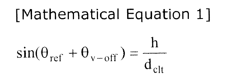

- In the above Mathematical Equations, if θv_off is positive (+), it represents that the
radar 150 is deviated downward from a reference position, and if θv_off is negative (-), it represents that theradar 150 is deviated upward from the reference position. - The
travel control system 310 checks whether or not the deviation angle θv_off (precisely, the absolute value of θv_off) is larger than a predetermined threshold value θv_th(S404). If the deviation angle θv_off is larger than the predetermined threshold value θv_th, it is determined that theradar 150 is misaligned in the vertical direction and the sequence proceeds to step S405. If the deviation angle θv_off is not larger than the predetermined threshold value θv_th, the sequence returns to the step S401 so that the above-described steps are repeated. - In the case where it is determined in the step S404 that the
radar 150 is misaligned in the vertical direction, it is alarmed to a driver that theradar 150 is misaligned in the vertical direction, the alarm is made and theradar 150 is deactivated, or the vertical deviation angle θv_off of theradar 150 is compensated for (S405). In other words, when it is determined that theradar 150 is misaligned in the vertical direction, thetravel control system 310 may cause thealarm unit 320 to issue an alarm to the driver through a sound or a visual display, and in addition, may deactivate theradar 150. - Moreover, when it is determined that the
radar 150 is misaligned in the vertical direction, thetravel control system 310 may cause thecompensation unit 330 to compensate for the vertical deviation angle θv_off of theradar 150. In this case, the compensation of the vertical deviation angle θv_off may be implemented in such a way as to compensate for an array factor of a transmission antenna of theradar 150 to thereby compensate for the vertical deviation angle θv_off in terms of software or physically compensate for the vertical deviation angle θv_off of theradar 150 through driving a motor (not shown). Namely, by compensating for or correcting the array factor of the transmission antenna in terms of software, the radiation direction of the radio wave or a main beam and a side beam radiated from theradar 150 may be corrected. Otherwise, a driving unit, such as a step motor, installed at theradar 150 may be used to physically correct the radiation direction of theradar 150. - Thus, the alignment method and system for a radar of a vehicle in accordance with the first embodiment of the present invention can automatically detect a vertical or horizontal misalignment of a radar mounted to the front part of a vehicle and can alarm a driver or automatically correct the misalignment.
-
FIG. 5 is a conceptual view explaining a horizontal alignment method for a radar of a vehicle in accordance with a second embodiment of the present invention,FIG. 6 is a conceptual view explaining a vertical alignment method for a radar of a vehicle in accordance with a third embodiment of the present invention,FIG. 7 is a schematic block diagram showing the configuration of a horizontal or vertical alignment system for a radar of a vehicle according to the second and third embodiments of the present invention,FIG. 8 is a flow chart showing the horizontal alignment method for a radar of a vehicle according to the second embodiment of the present invention, andFIG. 9 is a flow chart showing the vertical alignment method for a radar of a vehicle according to the third embodiment of the present invention. - Referring to
FIG. 7 , a horizontal or vertical alignment system for a radar of a vehicle according to second and third embodiments of the present invention includes a horizontal orvertical slope sensor 1151 installed in aradar 1150 of avehicle 1100; a horizontal orvertical slope sensor 1111 installed in asensor cluster 1110 of thevehicle 1100; atravel control system 1310 configured to determine whether or not a horizontal or vertical misalignment of theradar 1150 occurs, based on a first horizontal or vertical slope from the horizontal orvertical slope sensor 1151 and a second horizontal or vertical slope from the horizontal orvertical slope sensor 1111; analarm unit 1320 configured to alarm a driver in response to a misalignment determination result from thetravel control system 1310; and acompensation unit 1330 configured to compensate for a horizontal or vertical deviation angle of theradar 1150 in response to the misalignment determination result from thetravel control system 1310. - First, a horizontal alignment method for a radar of a vehicle in accordance with the second embodiment of the present invention will be described below with reference to
FIGS. 5 ,7 and8 . - A first horizontal slope is received from the slope sensor installed in the
radar 1150 of thevehicle 1100, in particular, thehorizontal slope sensor 1151, and a second horizontal slope is received from the slope sensor installed in thesensor cluster 1110 of thevehicle 1100, in particular, the horizontal slope sensor 1111 (S1401). Thehorizontal slope sensor 1151 is mounted in theradar 1150 which is installed at an appropriate position of thevehicle 1100, and senses a leftward and rightward slope when viewed in the horizontal direction, that is, in the straightforward direction of thevehicle 1100. Therefore, thehorizontal slope sensor 1151 senses a degree to which theradar 1150 is deviated from the horizontal direction. - Also, the
horizontal slope sensor 1111 is mounted in thesensor cluster 1110 of thevehicle 1100, and senses a leftward and rightward slope when viewed in the horizontal direction, that is, in the straightforward direction of thevehicle 1100. Therefore, thehorizontal slope sensor 1111 senses a degree to which the body of thevehicle 1100 is deviated from the horizontal direction. Thesensor cluster 1110 is mainly installed under a console box which is positioned near the center of gravity of thevehicle 1100, and has various sensors mounted therein. - Next, the
travel control system 1310 determines whether or not a horizontal misalignment of theradar 1150 occurs, based on the first horizontal slope and the second horizontal slope. Describing this in a stepwise manner, thetravel control system 1310 calculates a difference between the first horizontal slope and the second horizontal slope (S1402). Then, thetravel control system 1310 checks whether or not the difference between the first horizontal slope and the second horizontal slope is larger than a predetermined threshold value θh_th, and thereby determines whether or not the misalignment occurs (S1403). That is to say, if the difference between the first horizontal slope and the second horizontal slope is larger than a predetermined threshold value θh_th, it represents that theradar 1150 is deviated no less than a predetermined degree with respect to the straightforward horizontal direction of thevehicle 1100. Through this, thetravel control system 1310 may determine whether or not a horizontal misalignment of theradar 1150 occurs. If it is determined as a determination result of the step S1403 that a misalignment occurs, the sequence proceeds to step S1404. Otherwise, the sequence returns to the step S1401 so that the above-described steps are repeated. - In the case where it is determined in the step S1403 that a horizontal misalignment of the
radar 1150 occurs, it is alarmed to a driver that theradar 1150 is misaligned in the horizontal direction, and a horizontal deviation angle θh_off of theradar 1150 is compensated for (S1404). In other words, when it is determined that theradar 1150 is misaligned in the horizontal direction, thetravel control system 1310 may cause thealarm unit 1320 to issue an alarm to the driver through a sound or a visual display. Further, when it is determined that theradar 1150 is misaligned in the horizontal direction, thetravel control system 1310 may cause thecompensation unit 1330 to compensate for the horizontal deviation angle θh_off of theradar 1150. In this case, the compensation of the horizontal deviation angle θh_off may be implemented in such a way as to compensate for an array factor of a transmission antenna of theradar 1150 to thereby compensate for the horizontal deviation angle θh_off in terms of software or physically compensate for the horizontal deviation angle θh_off of theradar 1150 through driving a motor (not shown). Namely, by compensating for or correcting the array factor of the transmission antenna in terms of software, the radiation direction of the radio wave or a main beam and a side beam radiated from theradar 1150 may be corrected. Or, a driving unit, such as a step motor, installed at theradar 1150 may be used to physically correct the radiation direction of theradar 1150. - Thus, the alignment method and system for a radar of a vehicle in accordance with the second embodiment of the present invention can automatically detect a horizontal misalignment of a radar mounted to a vehicle and can alarm a driver or automatically correct the misalignment.
- Next, a vertical alignment method for a radar of a vehicle in accordance with the third embodiment of the present invention will be described below with reference to
FIGS. 6, 7 and9 . Descriptions for the same components as those of the second embodiment will be omitted herein. - A first vertical slope is received from the slope sensor installed in the
radar 1150 of thevehicle 1100, in particular, thevertical slope sensor 1151, and a second vertical slope is received from the slope sensor installed in thesensor cluster 1110 of thevehicle 1100, in particular, the vertical slope sensor 1111 (S1501). Thevertical slope sensor 1151 is mounted in theradar 1150, and senses an upward and downward slope when viewed in the vertical direction, that is, in the upward and downward direction of thevehicle 1100. Therefore, thevertical slope sensor 1151 senses a degree to which theradar 1150 is deviated from the vertical direction. - Also, the
vertical slope sensor 1111 is mounted in thesensor cluster 1110 of thevehicle 1100, and senses an upward and downward slope when viewed in the vertical direction, that is, in the upward and downward direction of thevehicle 1100. Therefore, thevertical slope sensor 1111 senses a degree to which the body of thevehicle 1100 is deviated from the vertical direction. - Next, the
travel control system 1310 determines whether or not a vertical misalignment of theradar 1150 occurs, based on the first vertical slope and the second vertical slope. Describing this in a stepwise manner, thetravel control system 1310 calculates a difference between the first vertical slope and the second vertical slope (S1502). Then, thetravel control system 1310 checks whether or not the difference between the first vertical slope and the second vertical slope is larger than a predetermined threshold value θv_th, and thereby determines whether or not the misalignment occurs (S1503). That is to say, if the difference between the first vertical slope and the second vertical slope is larger than a predetermined threshold value θv_th, it represents that theradar 1150 is deviated no less than a predetermined degree with respect to the vertical direction of thevehicle 1100. Through this, thetravel control system 1310 may determine whether or not a vertical misalignment of theradar 1150 occurs. If it is determined as a determination result of the step S1503 that a misalignment occurs, the sequence proceeds to step S1504. Otherwise, the sequence returns to the step S1501 so that the above-described steps are repeated. - In the case where it is determined in the step S1503 that a vertical misalignment of the
radar 1150 occurs, it is alarmed to a driver that theradar 1150 is misaligned in the vertical direction, and a vertical deviation angle θv_off of theradar 1150 is compensated for (S1504). In other words, when it is determined that theradar 1150 is misaligned in the vertical direction, thetravel control system 1310 may cause thealarm unit 1320 to issue an alarm to the driver through a sound or a visual display. Further, when it is determined that theradar 1150 is misaligned in the vertical direction, thetravel control system 1310 may cause thecompensation unit 1330 to compensate for the vertical deviation angle θv_off of theradar 1150. In this case, the compensation of the vertical deviation angle θv_off may be implemented in such a way as to compensate for an array factor of a transmission antenna of theradar 1150 to thereby compensate for the vertical deviation angle θv_off in terms of software or physically compensate for the vertical deviation angle θv_off of theradar 1150 through driving a motor (not shown). Namely, by compensating for or correcting the array factor of the transmission antenna in terms of software, the radiation direction of the radio wave or a main beam and a side beam radiated from theradar 1150 may be corrected. Otherwise, a driving unit, such as a step motor, installed at theradar 1150 may be used to physically correct the radiation direction of theradar 1150. - Thus, the alignment method and system for a radar of a vehicle in accordance with the third embodiment of the present invention can automatically detect a vertical misalignment of a radar mounted to a vehicle and can alarm a driver or automatically correct the misalignment.
- As is apparent from the above descriptions, the alignment method and system for a radar of a vehicle according to the present invention provide advantages in that it is possible to automatically detect a vertical or horizontal misalignment of a radar mounted to a vehicle and to alarm a driver or automatically correct the misalignment.
- The embodiments of the present invention have been disclosed above for illustrative purposes. Those skilled in the art will appreciate that various modifications, additions and substitutions are possible, without departing from the scope and spirit of the invention as disclosed in the accompanying claims.
Claims (15)
- A vertical alignment method for a radar of a vehicle, characterized by comprising the steps of:radiating radio wave to a forward ground by a radar which is installed on the vehicle;receiving reflected wave which is reflected from the ground;calculating a vertical deviation angle of the radar based on a frequency spectrum of the reflected wave; andchecking whether or not the vertical deviation angle is larger than a predetermined threshold value.
- The method according to claim 1, characterized in that the vertical deviation angle is determined by a distance between the radar and the forward ground that is obtained by the frequency spectrum of the reflected wave.
- The method according to claim 1, characterized by further comprising the step of compensating for the vertical deviation angle of the radar in the case where it is determined that the vertical deviation angle is larger than the predetermined threshold value; and
characterized in that the step of compensating for the vertical deviation angle of the radar is implemented in such a way as to compensate for the vertical deviation angle in terms of software by compensating for an array factor of a transmission antenna of the radar. - The method according to claim 1, characterized by further comprising the step of compensating for the vertical deviation angle of the radar in the case where it is determined that the vertical deviation angle is larger than the predetermined threshold value; and
characterized in that the step of compensating for the vertical deviation angle of the radar is implemented in such a way as to physically compensate for the vertical deviation angle of the radar through driving a motor installed at the radar. - A vertical alignment system for a radar of a vehicle, characterized by comprising:a radar mounted to a vehicle and configured to radiate radio wave to a forward ground and receive reflected wave; anda misalignment determination unit configured to determine whether or not a vertical misalignment of the radar occurs, based on the reflected wave,and characterized in that the misalignment determination unit calculates a vertical deviation angle based on a frequency spectrum of the reflected wave, and determines whether or not a vertical misalignment of the radar occurs, by comparing the vertical deviation angle with a predetermined threshold value.
- The system according to claim 5, characterized in that the vertical deviation angle is determined by a distance between the radar and the forward ground that is obtained by the frequency spectrum of the reflected wave.
- The system according to claim 5, characterized by further comprising a compensation unit configured to compensate for the vertical deviation angle in response to a misalignment determination result from the misalignment determination unit; and
characterized in that the compensation unit compensates for an array factor of a transmission antenna of the radar to thereby compensate for the vertical deviation angle in terms of software. - The system according to claim 5, characterized by further comprising a compensation unit configured to compensate for the vertical deviation angle in response to a misalignment determination result from the misalignment determination unit; and
characterized in that the compensation unit physically compensates for the vertical deviation angle of the radar through driving a motor installed at the radar. - The system according to claim 5,
characterized in that the radar comprises an array antenna which has at least two antenna elements, and
the radio wave radiated to the forward ground comprises a side beam. - A horizontal alignment method for a radar of a vehicle, characterized by comprising the steps of:receiving a first horizontal slope from a first horizontal slope sensor installed in the radar of the vehicle and a second horizontal slope from a second horizontal slope sensor installed in a sensor cluster of the vehicle;calculating a difference between the first horizontal slope and the second horizontal slope; andchecking whether or not the difference between the first horizontal slope and the second horizontal slope is larger than a predetermined horizontal slope threshold value.
- The method according to claim 10, characterized by further comprising the step of compensating for a horizontal deviation angle of the radar in the case where it is determined that the difference between the first horizontal slope and the second horizontal slope is larger than the predetermined horizontal slope threshold value; and
characterized in that the step of compensating for the horizontal deviation angle of the radar is implemented in such a way as to compensate for an array factor of a transmission antenna of the radar to thereby compensate for the horizontal deviation angle in terms of software, or to physically compensate for the horizontal deviation angle of the radar through driving a motor installed at the radar. - A horizontal alignment system for a radar of a vehicle, characterized by comprising:a first horizontal slope sensor installed in a radar of a vehicle;a second horizontal slope sensor installed in a sensor cluster of the vehicle;a travel control system configured to determine whether or not a horizontal misalignment of the radar occurs, based on a first horizontal slope from the first horizontal slope sensor and a second horizontal slope from the second horizontal slope sensor; anda compensation unit configured to compensate for a horizontal deviation angle of the radar in response to a misalignment determination result from the travel control system,wherein the travel control system calculates a difference between the first horizontal slope and the second horizontal slope and checks whether or not the difference between the first horizontal slope and the second horizontal slope is larger than a predetermined horizontal slope threshold value
- A vertical alignment method for a radar of a vehicle, characterized by comprising the steps of:receiving a first vertical slope from a first vertical slope sensor installed in the radar of the vehicle and a second vertical slope from a second vertical slope sensor installed in a sensor cluster of the vehicle;calculating a difference between the first vertical slope and the second vertical slope; andchecking whether or not the difference between the first vertical slope and the second vertical slope is larger than a predetermined vertical slope threshold value.
- The method according to claim 13, characterized by further comprising the step of compensating for a vertical deviation angle of the radar in the case where it is determined that the difference between the first vertical slope and the second vertical slope is larger than the predetermined vertical slope threshold value; and
characterized in that the step of compensating for the vertical deviation angle of the radar is implemented in such a way as to compensate for an array factor of a transmission antenna of the radar to thereby compensate for the vertical deviation angle in terms of software, or to physically compensate for the vertical deviation angle of the radar through driving a motor installed at the radar. - A vertical alignment system for a radar of a vehicle, characterized by comprising:a first vertical slope sensor installed in a radar of a vehicle;a second vertical slope sensor installed in a sensor cluster of the vehicle;a travel control system configured to determine whether or not a vertical misalignment of the radar occurs, based on a first vertical slope from the first vertical slope sensor and a second vertical slope from the second vertical slope sensor; anda compensation unit configured to compensate for a vertical deviation angle of the radar in response to a misalignment determination result from the travel control system,wherein the travel control system calculates a difference between the first vertical slope and the second vertical slope and checks whether or not the difference between the first vertical slope and the second vertical slope is larger than a predetermined vertical slope threshold value.
Applications Claiming Priority (2)
| Application Number | Priority Date | Filing Date | Title |
|---|---|---|---|
| KR1020110024044A KR20120106143A (en) | 2011-03-17 | 2011-03-17 | Method of alignment of radar of vihecle in the horizontal or vertical direction |
| KR1020110024043A KR101248851B1 (en) | 2011-03-17 | 2011-03-17 | Method and System of Alignment of Radar of Vihecle in the Vertical Direction |
Publications (2)
| Publication Number | Publication Date |
|---|---|
| EP2500745A2 true EP2500745A2 (en) | 2012-09-19 |
| EP2500745A3 EP2500745A3 (en) | 2015-07-08 |
Family
ID=44651266
Family Applications (1)
| Application Number | Title | Priority Date | Filing Date |
|---|---|---|---|
| EP11180492.8A Withdrawn EP2500745A3 (en) | 2011-03-17 | 2011-09-08 | Alignment method and system for radar of vehicle |
Country Status (4)
| Country | Link |
|---|---|
| US (1) | US9523769B2 (en) |
| EP (1) | EP2500745A3 (en) |
| JP (2) | JP2012194169A (en) |
| CN (1) | CN102680952B (en) |
Cited By (1)
| Publication number | Priority date | Publication date | Assignee | Title |
|---|---|---|---|---|
| CN109313262A (en) * | 2016-02-26 | 2019-02-05 | 伟摩有限责任公司 | Radar installation estimation using unstructured data |
Families Citing this family (28)
| Publication number | Priority date | Publication date | Assignee | Title |
|---|---|---|---|---|
| US9423498B1 (en) * | 2012-09-25 | 2016-08-23 | Google Inc. | Use of motion data in the processing of automotive radar image processing |
| KR101997433B1 (en) * | 2012-11-23 | 2019-10-01 | 현대모비스 주식회사 | Method for detecting installation position of vehicle radar sensor |
| DE102013209494A1 (en) * | 2013-05-22 | 2014-11-27 | Robert Bosch Gmbh | Method and device for determining a misalignment of a radar sensor of a vehicle |
| DE102013209530A1 (en) * | 2013-05-23 | 2014-11-27 | Robert Bosch Gmbh | DETERMINATION OF AN ELVAGE DEJUSTING ANGLE OF A RADAR SENSOR OF A MOTOR VEHICLE |
| JP6321448B2 (en) | 2013-06-03 | 2018-05-09 | 株式会社デンソー | Radar apparatus and program |
| JP6464241B2 (en) * | 2013-06-03 | 2019-02-06 | 株式会社デンソー | Radar apparatus and program |
| KR101558660B1 (en) * | 2013-10-10 | 2015-10-07 | 현대자동차주식회사 | Apparatus for correcting beam angle of multi-layer lidar |
| JP6146285B2 (en) | 2013-12-02 | 2017-06-14 | 株式会社デンソー | Axis deviation judgment device |
| KR101993153B1 (en) * | 2014-02-27 | 2019-06-26 | 주식회사 만도 | Apparatus and method for vertical alignment of radar for vehicle |
| US10585170B2 (en) * | 2014-08-15 | 2020-03-10 | Robert Bosch Gbmh | Automotive radar alignment |
| JP6323256B2 (en) * | 2014-08-27 | 2018-05-16 | 株式会社デンソー | Detection device |
| JP6265149B2 (en) * | 2014-08-27 | 2018-01-24 | 株式会社デンソー | Detection device |
| US11137490B2 (en) * | 2014-09-16 | 2021-10-05 | Teknologian Tutkimuskeskus Vtt | Navigational aid with adaptive radar |
| KR20160081506A (en) | 2014-12-31 | 2016-07-08 | 현대모비스 주식회사 | Alignment correction system and a control method of a radar and the side of the vehicle |
| US20160223649A1 (en) * | 2015-01-30 | 2016-08-04 | Robert Bosch Gmbh | Systems and methods for radar vertical misalignment detection |
| KR101649987B1 (en) * | 2015-04-13 | 2016-08-23 | 주식회사 만도 | Installation angle distinction apparatus and distinction method thereof |
| JP2018059783A (en) * | 2016-10-04 | 2018-04-12 | 株式会社デンソー | Method for determining axial misalignment of object detection sensor |
| CN108614256A (en) * | 2016-12-12 | 2018-10-02 | 北京行易道科技有限公司 | Calibration system and method |
| TWI684778B (en) * | 2018-03-26 | 2020-02-11 | 為升電裝工業股份有限公司 | Anti-collision radar device for trailer-mounted vehicle |
| US11047955B2 (en) * | 2018-07-06 | 2021-06-29 | Lyft, Inc. | Calibrating a radar antenna |
| US11029390B2 (en) * | 2018-07-10 | 2021-06-08 | Ford Motor Company | Method and system for performing a vehicle height-radar alignment check to align a radar device provided in a vehicle |
| JP7339114B2 (en) * | 2019-10-09 | 2023-09-05 | 株式会社Soken | Axial misalignment estimator |
| US11360191B2 (en) * | 2019-12-27 | 2022-06-14 | Woven Planet North America, Inc. | Adaptive tilting radars for effective vehicle controls |
| US11305786B2 (en) * | 2020-05-01 | 2022-04-19 | Autoguide, LLC. | Maintaining consistent sensor output |
| KR102859813B1 (en) * | 2020-05-08 | 2025-09-16 | 주식회사 에이치엘클레무브 | Apparatus and Method for Detecting Vertical Misalignment of Radar Apparatus, and Radar Apparatus with the same |
| EP4293381B1 (en) * | 2022-06-15 | 2025-09-24 | Aptiv Technologies AG | Method for estimating a mounting position of a radar sensor |
| KR102587292B1 (en) * | 2022-07-25 | 2023-10-12 | 서울대학교산학협력단 | Radar placement and algorithm for ego-motion estimation |
| US20250172662A1 (en) * | 2023-11-29 | 2025-05-29 | Waymo Llc | Methods and Systems for Validating Automotive Radar Pitch using Elevation Sidelobe Measurements |
Citations (3)
| Publication number | Priority date | Publication date | Assignee | Title |
|---|---|---|---|---|
| US20040066325A1 (en) * | 2002-10-08 | 2004-04-08 | Zoratti Paul Kirk | Sensor alignment method and system |
| KR20110024043A (en) | 2009-09-01 | 2011-03-09 | 씨제이인터넷 주식회사 | System and method for providing online poker games with round dealing and blind betting |
| KR20110024044A (en) | 2009-09-01 | 2011-03-09 | 주식회사 동아지질 | Rod support of the ground improvement device |
Family Cites Families (23)
| Publication number | Priority date | Publication date | Assignee | Title |
|---|---|---|---|---|
| JP3082555B2 (en) * | 1994-01-19 | 2000-08-28 | トヨタ自動車株式会社 | In-vehicle radar device |
| JPH07253793A (en) * | 1994-03-15 | 1995-10-03 | Kaijo Corp | Directional beam stabilizing under water transmitting equipment |
| US5485156A (en) * | 1994-09-21 | 1996-01-16 | Alliedsignal Inc. | Antenna stabilization error correction system for radar |
| JPH10186024A (en) * | 1996-12-19 | 1998-07-14 | Yokogawa Denshi Kiki Kk | Range finder |
| JP2000056020A (en) * | 1998-08-07 | 2000-02-25 | Honda Motor Co Ltd | Object detection device |
| JP3664671B2 (en) * | 2001-08-02 | 2005-06-29 | 株式会社日立製作所 | Millimeter wave radar equipment |
| WO2003062852A1 (en) * | 2002-01-18 | 2003-07-31 | Hitachi,Ltd. | Radar device |
| DE10207437A1 (en) * | 2002-02-22 | 2003-09-11 | Bosch Gmbh Robert | Radar sensor for motor vehicles |
| JP2004085258A (en) * | 2002-08-23 | 2004-03-18 | Hitachi Ltd | Radar equipment |
| JP2004125739A (en) * | 2002-10-07 | 2004-04-22 | Omron Corp | Object detection apparatus and method |
| US6927699B2 (en) * | 2002-12-05 | 2005-08-09 | Denso Corporation | Object recognition apparatus for vehicle, and inter-vehicle distance control unit |
| JP2006047140A (en) * | 2004-08-05 | 2006-02-16 | Fujitsu Ten Ltd | Method and detector for detecting axial shift in radar system |
| US7327308B2 (en) * | 2005-04-28 | 2008-02-05 | Chung Shan Institute Of Science And Technology, Armaments Bureau, M.N.D. | Programmable method and test device for generating target for FMCW radar |
| US20070182623A1 (en) * | 2006-02-03 | 2007-08-09 | Shuqing Zeng | Method and apparatus for on-vehicle calibration and orientation of object-tracking systems |
| JP2006276023A (en) * | 2006-04-05 | 2006-10-12 | Omron Corp | Object detection apparatus and method |
| DE102008038615A1 (en) * | 2007-09-18 | 2009-03-19 | Continental Teves Ag & Co. Ohg | Sensor device and method for detecting the movement of a vehicle |
| DE102009009227B4 (en) * | 2008-02-21 | 2021-10-07 | Adc Automotive Distance Control Systems Gmbh | Method for the automatic alignment of a radiation sensor in a vehicle |
| JP2010127743A (en) * | 2008-11-27 | 2010-06-10 | Fujitsu Ten Ltd | Radar system and moving body |
| CN101750613A (en) * | 2008-12-02 | 2010-06-23 | 罗建平 | Vehicle velocity detection and display equipment and method |
| KR101053855B1 (en) * | 2009-01-22 | 2011-08-03 | 주식회사 만도 | Sensor vertical alignment regulator and sensor |
| CN101788659B (en) | 2009-01-22 | 2013-04-03 | 株式会社万都 | Apparatus and sensor for adjusting sensor vertical alignment |
| JP5551892B2 (en) * | 2009-06-19 | 2014-07-16 | 富士通テン株式会社 | Signal processing apparatus and radar apparatus |
| JPWO2011048831A1 (en) * | 2009-10-23 | 2013-03-07 | ボッシュ株式会社 | Obstacle detection device for vehicles |
-
2011
- 2011-08-19 JP JP2011179972A patent/JP2012194169A/en active Pending
- 2011-08-23 US US13/215,849 patent/US9523769B2/en active Active
- 2011-09-08 EP EP11180492.8A patent/EP2500745A3/en not_active Withdrawn
- 2011-09-15 CN CN201110272959.7A patent/CN102680952B/en active Active
-
2013
- 2013-06-19 JP JP2013129054A patent/JP2013213830A/en active Pending
Patent Citations (3)
| Publication number | Priority date | Publication date | Assignee | Title |
|---|---|---|---|---|
| US20040066325A1 (en) * | 2002-10-08 | 2004-04-08 | Zoratti Paul Kirk | Sensor alignment method and system |
| KR20110024043A (en) | 2009-09-01 | 2011-03-09 | 씨제이인터넷 주식회사 | System and method for providing online poker games with round dealing and blind betting |
| KR20110024044A (en) | 2009-09-01 | 2011-03-09 | 주식회사 동아지질 | Rod support of the ground improvement device |
Cited By (5)
| Publication number | Priority date | Publication date | Assignee | Title |
|---|---|---|---|---|
| CN109313262A (en) * | 2016-02-26 | 2019-02-05 | 伟摩有限责任公司 | Radar installation estimation using unstructured data |
| EP3420374A4 (en) * | 2016-02-26 | 2019-10-23 | Waymo Llc | RADAR MOUNTING ESTIMATION WITH UNSTRUCTURED DATA |
| AU2020201378B2 (en) * | 2016-02-26 | 2021-03-25 | Waymo Llc | Radar mounting estimation with unstructured data |
| US11016174B2 (en) | 2016-02-26 | 2021-05-25 | Waymo Llc | Radar mounting estimation with unstructured data |
| EP3913399A1 (en) * | 2016-02-26 | 2021-11-24 | Waymo LLC | Radar mounting estimation with unstructured data |
Also Published As
| Publication number | Publication date |
|---|---|
| CN102680952A (en) | 2012-09-19 |
| US20120235851A1 (en) | 2012-09-20 |
| EP2500745A3 (en) | 2015-07-08 |
| US9523769B2 (en) | 2016-12-20 |
| JP2013213830A (en) | 2013-10-17 |
| JP2012194169A (en) | 2012-10-11 |
| CN102680952B (en) | 2015-01-14 |
Similar Documents
| Publication | Publication Date | Title |
|---|---|---|
| EP2500745A2 (en) | Alignment method and system for radar of vehicle | |
| KR102179784B1 (en) | Method for calibrating sensors in automobiles for angle measurement, calculation devices, driver assistance systems, and automobiles | |
| KR102784531B1 (en) | Method for detecting angle measurement errors in radar sensors | |
| CN102066970B (en) | Radar sensor with frontal and lateral emission | |
| US10809355B2 (en) | Apparatus and method for detecting alignment of sensor and calibrating antenna pattern response in an automotive detection system | |
| US20110285571A1 (en) | Sensor and alignment adjusting method | |
| US8344940B2 (en) | Apparatus and sensor for adjusting sensor vertical alignment | |
| US9500748B2 (en) | Target recognition apparatus | |
| CN103907242A (en) | Radar system for a road vehicle with improved calibrating possibilities | |
| US10191148B2 (en) | Radar system for vehicle and method for measuring azimuth therein | |
| JP2007139690A (en) | Radar system | |
| KR101248851B1 (en) | Method and System of Alignment of Radar of Vihecle in the Vertical Direction | |
| KR20120106143A (en) | Method of alignment of radar of vihecle in the horizontal or vertical direction | |
| US20150048968A1 (en) | In-vehicle radar apparatus and target detection method thereof | |
| KR20150034349A (en) | Apparatus for compensating errors of sensors in a vehicle | |
| US10539659B2 (en) | Apparatus for detecting axial misalignment | |
| US11181614B2 (en) | Antenna array tilt and processing to eliminate false detections in a radar system | |
| EP1343020A1 (en) | Scanning radar | |
| CN112888961A (en) | Electronic device, control method for electronic device, and control program for electronic device | |
| US20240255612A1 (en) | Radar device | |
| US20250035743A1 (en) | Systems and methods for in-cabin sensor calibration | |
| KR101794620B1 (en) | Antenna beam center alignment method of radar system | |
| US20250189630A1 (en) | Alignment detection for a vehicle radar transceiver | |
| JP2022030095A (en) | Axis misalignment estimation device | |
| US12204020B2 (en) | Object detection device |
Legal Events
| Date | Code | Title | Description |
|---|---|---|---|
| PUAI | Public reference made under article 153(3) epc to a published international application that has entered the european phase |
Free format text: ORIGINAL CODE: 0009012 |
|
| 17P | Request for examination filed |
Effective date: 20110908 |
|
| AK | Designated contracting states |
Kind code of ref document: A2 Designated state(s): AL AT BE BG CH CY CZ DE DK EE ES FI FR GB GR HR HU IE IS IT LI LT LU LV MC MK MT NL NO PL PT RO RS SE SI SK SM TR |
|
| AX | Request for extension of the european patent |
Extension state: BA ME |
|
| RIC1 | Information provided on ipc code assigned before grant |
Ipc: G01S 13/93 20060101ALI20150216BHEP Ipc: G01S 7/40 20060101AFI20150216BHEP |
|
| PUAL | Search report despatched |
Free format text: ORIGINAL CODE: 0009013 |
|
| AK | Designated contracting states |
Kind code of ref document: A3 Designated state(s): AL AT BE BG CH CY CZ DE DK EE ES FI FR GB GR HR HU IE IS IT LI LT LU LV MC MK MT NL NO PL PT RO RS SE SI SK SM TR |
|
| AX | Request for extension of the european patent |
Extension state: BA ME |
|
| RIC1 | Information provided on ipc code assigned before grant |
Ipc: G01S 7/40 20060101AFI20150602BHEP Ipc: G01S 13/93 20060101ALI20150602BHEP |
|
| RAP1 | Party data changed (applicant data changed or rights of an application transferred) |
Owner name: HANWHA SYSTEMS CO., LTD. Owner name: HYUNDAI MOBIS CO., LTD. |
|
| 17Q | First examination report despatched |
Effective date: 20180227 |
|
| STAA | Information on the status of an ep patent application or granted ep patent |
Free format text: STATUS: THE APPLICATION IS DEEMED TO BE WITHDRAWN |
|
| 18D | Application deemed to be withdrawn |
Effective date: 20190827 |