EP2500732A2 - Specimen analyzer - Google Patents
Specimen analyzer Download PDFInfo
- Publication number
- EP2500732A2 EP2500732A2 EP12159459A EP12159459A EP2500732A2 EP 2500732 A2 EP2500732 A2 EP 2500732A2 EP 12159459 A EP12159459 A EP 12159459A EP 12159459 A EP12159459 A EP 12159459A EP 2500732 A2 EP2500732 A2 EP 2500732A2
- Authority
- EP
- European Patent Office
- Prior art keywords
- reagent container
- reagent
- housing
- container table
- specimen analyzer
- Prior art date
- Legal status (The legal status is an assumption and is not a legal conclusion. Google has not performed a legal analysis and makes no representation as to the accuracy of the status listed.)
- Withdrawn
Links
Images






Classifications
-
- G—PHYSICS
- G01—MEASURING; TESTING
- G01N—INVESTIGATING OR ANALYSING MATERIALS BY DETERMINING THEIR CHEMICAL OR PHYSICAL PROPERTIES
- G01N35/00—Automatic analysis not limited to methods or materials provided for in any single one of groups G01N1/00 - G01N33/00; Handling materials therefor
- G01N35/02—Automatic analysis not limited to methods or materials provided for in any single one of groups G01N1/00 - G01N33/00; Handling materials therefor using a plurality of sample containers moved by a conveyor system past one or more treatment or analysis stations
- G01N35/04—Details of the conveyor system
-
- G—PHYSICS
- G01—MEASURING; TESTING
- G01N—INVESTIGATING OR ANALYSING MATERIALS BY DETERMINING THEIR CHEMICAL OR PHYSICAL PROPERTIES
- G01N35/00—Automatic analysis not limited to methods or materials provided for in any single one of groups G01N1/00 - G01N33/00; Handling materials therefor
-
- G—PHYSICS
- G01—MEASURING; TESTING
- G01N—INVESTIGATING OR ANALYSING MATERIALS BY DETERMINING THEIR CHEMICAL OR PHYSICAL PROPERTIES
- G01N35/00—Automatic analysis not limited to methods or materials provided for in any single one of groups G01N1/00 - G01N33/00; Handling materials therefor
- G01N2035/00178—Special arrangements of analysers
- G01N2035/00306—Housings, cabinets, control panels (details)
-
- G—PHYSICS
- G01—MEASURING; TESTING
- G01N—INVESTIGATING OR ANALYSING MATERIALS BY DETERMINING THEIR CHEMICAL OR PHYSICAL PROPERTIES
- G01N35/00—Automatic analysis not limited to methods or materials provided for in any single one of groups G01N1/00 - G01N33/00; Handling materials therefor
- G01N2035/00346—Heating or cooling arrangements
- G01N2035/00435—Refrigerated reagent storage
-
- G—PHYSICS
- G01—MEASURING; TESTING
- G01N—INVESTIGATING OR ANALYSING MATERIALS BY DETERMINING THEIR CHEMICAL OR PHYSICAL PROPERTIES
- G01N35/00—Automatic analysis not limited to methods or materials provided for in any single one of groups G01N1/00 - G01N33/00; Handling materials therefor
- G01N35/02—Automatic analysis not limited to methods or materials provided for in any single one of groups G01N1/00 - G01N33/00; Handling materials therefor using a plurality of sample containers moved by a conveyor system past one or more treatment or analysis stations
- G01N35/04—Details of the conveyor system
- G01N2035/0439—Rotary sample carriers, i.e. carousels
- G01N2035/0443—Rotary sample carriers, i.e. carousels for reagents
-
- G—PHYSICS
- G01—MEASURING; TESTING
- G01N—INVESTIGATING OR ANALYSING MATERIALS BY DETERMINING THEIR CHEMICAL OR PHYSICAL PROPERTIES
- G01N35/00—Automatic analysis not limited to methods or materials provided for in any single one of groups G01N1/00 - G01N33/00; Handling materials therefor
- G01N35/02—Automatic analysis not limited to methods or materials provided for in any single one of groups G01N1/00 - G01N33/00; Handling materials therefor using a plurality of sample containers moved by a conveyor system past one or more treatment or analysis stations
- G01N35/04—Details of the conveyor system
- G01N2035/0439—Rotary sample carriers, i.e. carousels
- G01N2035/0453—Multiple carousels working in parallel
- G01N2035/0455—Coaxial carousels
Definitions
- the present invention relates to a specimen analyzer for analyzing a sample using a cooled reagent.
- specimen analyzers provided with a reagent refrigerator for cooling reagent within an accommodated reagent container, wherein the specimen analyzer analyzes specimens using the reagent cooled within a reagent refrigerator
- the reagent refrigerator disclosed in U.S. Patent Application Publication No. 2009/0004057 is configured to accommodate a reagent container within a reagent case that is cooled by Peltier element, and cool the reagent within the reagent container by circulating the air within the reagent case via a circulation unit, the reagent case being formed of a material that has excellent thermal conductivity, such as aluminum or the like.
- the reagent refrigerator disclosed in U.S. Patent Application Publication No. 2009/0004057 readily generates condensation, particularly in the reagent case, because the reagent case has high thermal conductivity and is cooled by a Peltier element.
- condensation water adhering to the reagent container may interfere with the reading of the barcode label adhered to the reagent container, and there is further concern that condensation water may penetrate into the reagent container.
- an object of the present invention is to provide a specimen analyzer capable of inhibiting adhesion of condensation water on the reagent container when the reagent container is set in the reagent refrigerator.
- adhesion of condensation water on the reagent container can be prevented when the reagent container is set within the reagent refrigerator.
- FIG. 1 is a perspective view showing the general structure of a specimen analyzer 1 of an embodiment of the present invention.
- the specimen analyzer 1 is an apparatus for performing specific measurements of a measurement sample prepared by mixing a reagent and a specimen collected from a human body, then analyzing the specimen based on the measurement results, and is, for example, a blood coagulation measuring apparatus, immunoanalyzer, or biochemical analyzer.
- the specimen analyzer 1 is configured by a measuring device 2, and a control device 4 that is electrically connected to the measuring device 2.
- a reagent refrigerator 10 for accommodating and cooling a plurality of reagent containers which hold reagent.
- the casing 5 of the measuring device 2 has a cover body 5A that can be opened and closed; at least part of the reagent refrigerator 10 can be exposed by opening the cover body 5A.
- FIG. 2 is a brief structural view of the specimen analyzer 1 f FIG. 1 .
- the measuring device 2 of the specimen analyzer 1 is provided with, in addition to the reagent refrigerator 10, a specimen supply unit 12, transport drive unit 13, dispensing section 14, measuring unit 15, reader 33, and control circuit 16.
- the specimen supply unit 12 has the function of setting a specimen rack that holds specimen containers (test tubes or the like) containing a specimen, and positioning each specimen container at a predetermined dispensing position by transporting the specimen rack.
- the transport drive unit 13 has the function of transporting the reagent container accommodated in the reagent refrigerator 10 to the predetermined dispensing position.
- the dispensing section 14 has the function of dispensing specimen and reagent from the specimen container and reagent container positioned at the predetermined dispensing positions to prepare a measurement sample.
- FIG. 3 is a plan view showing the reagent refrigerator 10 and the dispensing section 14. As shown in FIG. 3 , the dispensing section 14 has a plurality of dispensing units 25 through 29; each dispensing unit 25 through 29 is capable of dispensing reagent from within the reagent container accommodated in the reagent refrigerator 10.
- the dispensing unit 25 has a support 25a, an arm 25b wherein the base end is supported by the support 25a, and a pipette 25c provided at the tip of the arm 25b.
- the arm 25b is driven to pivot on the base end to rotate in horizontal directions and is further driven to ascend and descent in vertical directions.
- the pipette 25c is inserted into an aspiration hole 71 formed in the top surface of the reagent refrigerator 10, and aspirates reagent from the reagent container 300 (refer to FIG. 5 ) within the reagent refrigerator 10 via the horizontal rotation and vertical elevator action of the arm 25b.
- the other dispensing units 26 through 29 have structures identical to that of the dispensing unit 25, and their detailed description is therefore omitted.
- the measuring unit 15 has the function of performing specific measurements of the measurement sample prepared by mixing a specimen and reagent.
- the reader 33 is a barcode reader for reading a barcode adhered to the reagent container racks 310 and 320 (refer to FIG. 5 ) that accommodate the reagent container 300, and the reagent container 300 accommodated in the reagent refrigerator 10.
- the reagent container 300 has a side surface 300a. The barcode is adhered to the side surface 300a.
- the reader 33 is disposed outside the reagent refrigerator 10, and is capable of reading a barcode within the reagent refrigerator 10 through a slit (not shown in the drawing) which is formed in the reagent refrigerator 10 and is opened and closed via a shutter.
- the control circuit 16 has a CPU, memory such as RAM, ROM or the like, and a communication interface; the control circuit 16 has the function of controlling the operations of the reagent refrigerator 10, transport drive unit 13, dispensing unit 14, measuring unit 15, and reader 33, and transmitting and receiving various types of information to/from the control device , to which the control circuit 16 is connected so as to be capable of communication.
- the control device 4 is a personal computer 401 (PC), and includes a controller 4a, display 4b, and keyboard 4c for inputting information.
- the controller 4a has the functions of transmitting an operation start signal of the measuring device 2 to the control circuit 16 of the measuring device 2, and analyzing the information of the measurement result obtained by the measuring device 2.
- the display 4b has the function of displaying the analysis result obtained by the controller 4a.
- FIG. 5 is a side sectional view briefly showing the reagent refrigerator 10.
- the reagent refrigerator 10 is provided to refrigerate the reagent container 300 containing a reagent to be added to a specimen, and transport the reagent container 300 in a rotational direction around an axis O. The reagent is prevented from degenerating by being preserved at low temperature.
- the reagent refrigerator 10 is provided with a housing 20, and reagent container tables 21 and 22 arranged within the housing 20 and loaded with reagent containers 300 containing reagent.
- the reagent container tables 21 and 22 are configured by annular first reagent table 21, and an annular reagent container table 22 arranged concentrically with the first reagent container table 21 and on the outer side in the diameter direction of the first reagent container table 21.
- the first reagent container table 21 and the second reagent container table 22 are arranged so that the first reagent container rack 310 and the second reagent container rack 320 holding a plurality of reagent containers 300 are respectively detachable.
- the first reagent container table 21 and the second reagent container table 22 are respectively and independently rotatable in both clockwise and counterclockwise directions on the axis O via the transport drive unit 13. Hence, the reagent containers 300 set on the reagent container tables 21 and 22 are transported in rotational directions. Each reagent container 300 is positioned at the dispensing position of the dispensing units 25 through 29 by transporting the reagent container 300 in a rotational direction. Details of the structure of the transport drive unit 13 are described later.
- the reagent refrigerator 10 and the housing 20 are provided with a solid-bottom cylindrical shaped main body 65 with a bottom wall 63 forming the bottom part of the housing 20 and a circumferential wall (side wall) 64 rising from the periphery of a bottom wall 63, and a cover 66 that functions as a top wall of the reagent refrigerator 10 by closing the top opening of the main body 65.
- the sealed space circumscribed by the main body 65 and the cover 66 is a refrigeration chamber, and the plurality of reagent containers 300 set in the reagent container tables 21 and 22 within the refrigeration chamber are enclosed completely therein on the outside in the diameter direction (outside in the horizontal direction) by the circumferential wall 64.
- the cover 66 is configured by a fixed cover 67 that closes approximately the back half of the main body 65, and a movable cover 68 that closes the approximate front half of the main body 65 and is openable.
- the movable cover 68 is coupled to the front edge of the fixed cover 67 so as to oscillate through a hinge member 69.
- the cover 66 of the housing 20 has a plurality of aspiration holes 71 formed therein; these aspiration holes 71 are configured so that the pipette 25c of the dispensing units 25 through 29 can be inserted, and the reagent within the reagent container 300 held in the reagent refrigerator 10 can be aspirated from the top opening of the reagent container 300.
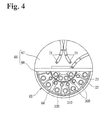
- FIG. 4 is a plan view of the reagent refrigerator showing the cover 66 in the open condition. When the cover 66 is open, the interior of the main body 65 is exposed, and the reagent racks 310 and 320 holding the reagent containers 300 can be inserted into the main body 65 and removed from the main body 65.
- the circumferential wall (side wall) 64 of the main body 65 of the housing 20 is formed of a material having low thermal conductivity.
- the bottom wall 63 has different material for the outer part 77 and the heat transfer layer 78; the outer part 77 is formed of the same low thermal conductivity material as the circumferential wall 64 and is linked to the bottom end of the circumferential wall 64.
- the heat transfer layer 78 of the bottom wall 63 is formed of a material that has a higher thermal conductivity than the circumferential wall 64 and the outer part 77, and protrudes upward from the outer part 77.
- the circumferential wall 64, bottom wall 63, and outer part 77 of the main body 65 may be formed of thermoplastic resin such as ABS and the like.
- the heat transfer layer 78 may be formed of a metal such as aluminum, iron, steel and the like.
- the outer surface of the circumferential wall 64 and the bottom wall 63 are covered by thermal shield layers 76 and 79 that have lower thermal conductivity.
- FIG. 6 is a horizontal cross sectional view of the inner bottom surface of the reagent refrigerator 10 viewed from above.
- the heat transfer layer 78 provided on the bottom wall 63 of the housing 20 is formed in a polygonal shape (hexagonal shape in the example of the drawing) in the plan view.
- part of the bottom surface of the heat transfer layer 78 is exposed below, and a cooler 80 is provided on this exposed surface.
- two coolers 80 are arranged at symmetrical positions centered on the central axis O of the reagent refrigerator 10 (that is, the center of rotation of the first and second reagent container tables 21 and 22).
- the cooler 80 is configured to cool the air within the reagent refrigerator 10 using the heat transfer layer 78 as a cooling medium by directly cooling the heat transfer layer 78 which has a high thermal conductivity. Note that the cooler 80 is not limited to using a Peltier element, and also may provide cooling, for example, by air cooling or water cooling the heat transfer layer 78.
- the planar shape of the heat transfer layer 78 is not limited a polygonal shape, and also may be circular.
- An upright wall member 81 is provided in the circumferential direction along the circumferential wall 64 on the inside of the circumferential wall 64 of the main body 65. As shown in FIG. 5 , the upright wall member 81 is positioned below the top surface of the first and second reagent container tables 21 and 22, and is separated form the inner surface of the circumferential wall 64 at the inner side of the circumferential wall 64. As shown in FIG. 6 , the upright wall member 81 is formed with an approximately circular shape in the plan view, and extends the approximate entire circumference of the housing 20. Note that the upright wall member 81 of the present embodiment has an approximately circular shape by curving a band-like plate in a polygonal shape.
- a mounting part 81a that protrudes inward in the diameter direction is provided at the bottom end of the upright wall member 81, and the upright wall member 81 is connected to the heat transfer layer 78 by the mounting part 81a being screwed to the top surface of the heat transfer layer 78.
- the upright wall member 81 is formed of metal, for example, aluminum, that is a material that has the same high thermal conductivity as the heat transfer layer 78.
- the upright wall member 81 connected to the heat transfer layer 78 and is cooled by the cooler 80.
- a heat sink (condensation promoting member) 82 is provided on the top surface of the heat transfer layer 78.
- the heat sink 82 is formed of a material having a high thermal conductivity such as aluminum, and increases the surface area by having a plurality of protuberances or fins. As shown in FIG. 6 , the heat sinks 82 are respectively provided positions above the two coolers 80, and are cooled by the coolers 80 through the heat transfer layer 78. Note that the heat transfer layer 78, upright wall member 81, and heat sink 82 configure the "second member" in the present embodiment.
- a cylindrical ventilation body 21d stands in the center of the first reagent container table 21, and a forced air fan (fan unit) 88 is provided within the ventilation body 21d.
- the forced air fan 88 is configured to blow the air taken in from above the ventilation body 21d downward in the ventilation body 21d, the ventilation body 21d being the air flow pass.
- the airflow produced by the forced air fan 88 therefore blows on the heat transfer layer 78 that is directly cooled by the cooler 80. The airflow is thus effectively cooled.
- the airflow produced by the forced air fan 88 flows outward in the radial direction after striking the heat transfer layer 78, and changes direction upward after striking the upright wall member 81, so that the air flows between the circumferential wall 64 (inside surface) of the reagent refrigerator 10 and the second reagent container table 22 and upward above the second reagent container table 22. Thereafter, the air flows in an inward radial direction along the bottom surface of the cover 66, and is taken into the top of the forced air body 21d so as to be once again blown downward by the forced air fan 88, hence, circulating the air within the reagent refrigerator 10.
- the reagent in the reagent container 300 placed in the first and second reagent container tables 21 and 22 is cooled to a desired temperature, for example, approximately 10 ⁇ , by the air circulated by the forced air fan 88.
- Condensation is facilitated by the heat transfer layer 78, upright wall member 81, and heat sink 82 because the high thermal conductivity heat transfer layer 78, upright wall member 81, and heat sink 82 are exposed in the region below the top surfaces of the first and second reagent container tables 21 and 22 and the heat transfer layer 78, upright wall member 81, and heat sink 82 are cooled by the coolers 80.
- condensation is inhibited mainly because the low thermal conductivity circumferential wall 64 (first member in the present invention) is arranged in the region above the top surfaces of the first and second reagent container tables 21 and 22.
- condensation is produced solely below the top surface of the first and second reagent container tables 21 and 22 and condensation is inhibited above the top surface of the first and second reagent container tables 21 and 22 even though warm outside air flows into the housing 20 when the movable cover 68 of the cover 66 is opened and a reagent container 30 is set inside the housing 20. Therefore, condensation water is prevented from adhering to the reagent container 300 even when the reagent container 300 comes into contact with the circumferential wall 64 while being set within the housing 20.
- the problem of condensation water adhering to the reagent container 300 and, for example, the problems of condensation water penetrating into the reagent container 300 and adversely affecting the reading of the barcode adhered on the reagent container 300 are likewise avoided.
- the circumferential wall 64 is directly cooled by the upright wall member 81 which is cooled by the cooler 80 since the upright wall member 81 is arranged a distance from the inner surface of the circumferential wall 64 on the inner side of the circumferential wall 64 of the housing 20.
- the circumferential wall 64 is therefore not overly cooled, and the formation of condensation on the circumferential wall 64 is inhibited.
- the upright wall member 81 is formed in a polygonal shape in plan view. As shown in FIG. 8 , the airflow at the inner surface of the upright wall member 81 is directed toward a corner angle 81b of the upright wall member 81, which changes the direction upward. Hence, the upright wall member 81 functions to direct the flow of the air upward.
- the air is effectively cooled since the airflow is within the entire inner surface of the upright wall member 81, which is cooled by the cooler 80.
- a cover heater 95 (refer to FIG. 5 ) is provided inside the cover 66, and the cover 66 is warmed by the cover heater 95.
- a channel 72 which extends along the movement track of the arm 25b of the dispensing units 25 through 29, is formed in the top surface of the cover 66, and an aspirating hole 71 is formed in the channel 72.
- the cover 66 becomes thin in the part of the channel 72, and is therefore easily cooled by the cool air in the housing 20 so that external air readily condenses. Condensation formation is prevented in the channel 72 and penetration of condensation water into the housing 20 from the aspirating hole 71 is prevented by providing the cover heater 95 inside the cover 66 in the region of the channel 72.
- the first and second reagent container tables 21 and 22 are driven in rotation by the transport drive unit 13.
- the transport drive unit 13 has a first drive body 97 and a second drive body 98 configured by stepper motors or the like.
- the first and second drive bodies 97 and 98 are arranged at the side of the housing 20, and a re connected to the first and second reagent container tables 21 and 22 through a power transmission device 99.
- the power transmission device 99 is configured by a first driven pulley 100, second driven pulley 101, first drive pulley 102, second drive pulley 103, first transmission belt 104, and second transmission belt 105.
- the first driven pulley 100 and the second driven pulley 101 are arranged on the center axis O of the reagent refrigerator 10, and are supported by the bottom part of the housing 20 so as to be relatively mutually rotatable.
- the first reagent container table 21 is connected to the first driven pulley 100, and the second reagent container table 22 is connected to the second driven pulley 101.
- the first driven pulley 102 is mounted on the output shaft of the first drive body 97
- the second drive pulley 103 is mounted on the output shaft of the second drive body 98.
- the first drive belt 104 is reeved around the first driven pulley 100 and the first drive pulley 102
- the second drive belt 105 is reeved around the second driven pulley 101 and the second drive pulley 103.
- the first reagent container table 21 can be rotated through the first drive pulley 102, first transmission belt 104, and first driven pulley 100 by operating the first drive body 97; the second reagent container table 22 can be rotated through the second drive pulley 103, first transmission belt 105, and second driven pulley 101 by operating the second drive body 98.
- a first insertion opening 107 and a second insertion opening 108 are formed in the circumferential wall 64 of the housing 20 for the first drive transmission belt 104 and the second drive transmission belt 105 to pass through.
- a chamber 109 At the side of the reagent refrigerator 10 is formed a chamber 109 to maintain airtightness and that is circumscribed by a heat insulating material; the receptacle 109 is connected to the reagent refrigerator 10 through the first insertion opening 107 and the second insertion opening 108.
- the first and second transmission belts 104 and 105 are arranged in the chamber 109. Therefore, since cool air is prevented within the chamber 109 even though the cool air within the housing 20 leaks from the first and second insertion openings 107 and 108, there is no reduction in the cooling efficiency within the housing 20.
- first drive body 97 and the second drive body 98 are arranged at the side of the reagent refrigerator 10, condensation does not adhere to the first drive body 97 and the second drive body 98 even when condensation water formed within the reagent refrigerator 10 spreads downward from the reagent refrigerator 10, hence damage to the first drive body 97 and the second drive body 98 is prevented.
- first drive body 97 and the second drive body 98 are not limited to the side of the reagent refrigerator 10, and may be arranged anywhere, even outside the reagent refrigerator 10, with the exclusion of below the reagent refrigerator 10.
- the power transmission device 99 is a transmission device employing drive belts reeved on pulleys, the present invention is not limited to this arrangement inasmuch as other drive transmission device also may be used, such as a gear transmission device.
- FIG. 7 is a side cross sectional view briefly showing the enlarged essential parts within the reagent refrigerator 10.
- the first reagent container table 21 has a first placement part 21a with a top surface 21h for setting a reagent container 300, and a first support part 21b for supporting the first placement part 21a from the bottom side; the center part of the first support part 21b is connected to the first driven pulley 100 so as to be integratedly rotatable.
- a plurality of first openings 21c are formed with spacing in the circumferential direction from the center (region below the forced air fan 88) of the first support part 21b, and air flows vertically through the first openings 21c.
- the outer circumference end of the first support part 21b is positioned outside in the radial direction from the outer circumference end of the first placement part 21a, and a concave step part 21e is formed in an approximate L-shape at the top surface side of the circumferential edge of the first reagent container table 21.
- the second reagent container table 22 has a second placement part 22a with a top surface 22h for setting a reagent container 300, and a second support part 22b for supporting the second placement part 22a from the bottom side; the center part of the second support part 22b is connected to the second driven pulley 101 so as to be integratedly rotatable.
- a plurality of second openings 22c are formed with spacing in the circumferential direction of the second support part 22b, and air flows vertically through the second openings 22c.
- the first placement part 21a of the first reagent container table 21 is made of synthetic resin such as ABS or the like
- the second placement part 22a of the second reagent container table 22 is made of metal such as aluminum or the like.
- the first placement part 21a of the first reagent container table 21 may be made of metal
- the second placement part 22a of the second reagent container table 22 may be made of synthetic resin, or both may be made of synthetic resin or of metal. From the perspective of inhibiting formation of condensation, the placement parts 21a and 22a of the first and second reagent container tables 21 and 22 are most suitably both made of low conductivity synthetic resin.
- the outer peripheral edge of the first reagent container table 21 and the inner peripheral edge of the second reagent container table 22 overlap in a vertical direction so that no space occurs between the tables 21 and 22 in the plan view.
- the dimension of the overlap of the tables 21 and 22 is designated t.
- the outer peripheral edge of the first reagent container table 21 is arranged on the bottom side of the inner peripheral edge of the second reagent container table 22. That is, when the airflow direction C below the first and second reagent container tables 21 and 22 is set as standard, the outer peripheral edge of the first reagent container table 21 positioned upstream of the airflow direction C is disposed below the inner peripheral edge of the second reagent container table 22 positioned on the downstream side. Therefore, the air flowing below the first and second reagent container tables 21 and 22 is unlikely to escape upward through the gap of the first and second reagent container tables 21 and 22. Below the first and second reagent container tables 21 and 22, an airflow can be reliably produced from the center of the housing 20 to the circumferential wall 64 of the housing 20, thus suitably producing circulating air within the housing 20.
- the inner peripheral edge of the second reagent container table 22 is arranged to fit into the step part 21e of the first reagent container table 21, so that the top surface of the first reagent container table 21 and the top surface of the second reagent container table 22 are mutually at the same height.
- the heights of the reagent containers 300 of both reagent container tables 21 and 22 are the same, and the elevator strokes of the pipette 25c in the dispensing units 25 through 29 (refer to FIG. 3 ) are uniform when aspirating reagent from the reagent container 300. Operational control of the dispensing units 25 through 29 is therefore simplified.
- both tables 21 and 22 can rotate smoothly with little rotational friction even without a gap between the tables 21 and 22 in the plan view.
- an annular first circumferential channel 135 is formed in the outer circumferential side of the heat transfer layer 78 provided on the bottom wall 63 of the housing 20.
- the first circumferential channel 135 has the function of collecting condensation water formed by the heat transfer layer 78.
- the first circumferential channel 135 is polygonal in shape (hexagonal in the example of the drawing) in plan view similar to the heat transfer layer 78.
- a first drain hole 136 is formed in the bottom surface of the first circumferential channel 135.
- FIG. 9 is a cross sectional view on the A-A arrow line in FIG. 6 .
- the first drain hole 136 is connected to a first drain pipe 137.
- the condensation water collected in the first circumferential channel 135 is discharged from the first drain hole 136 by periodically operating a pump (not shown in the drawing) that is connected to the first drain pipe 137.
- a second circumferential channel 110 is formed in the bottom surface of the outer circumferential part 77 between the heat transfer layer 78 and the circumferential wall 64.
- the second circumferential channel 110 is positioned below the upright wall member 81. Accordingly, the condensation water formed on the upright wall member 81 and the condensation water formed on the outer circumferential part of the heat transfer layer 78 is mainly collected in the second circumferential channel 110.
- a second drain hole 121 and a third drain hole 131 are formed in the second circumferential channel 110.
- the third drain hole 131 is formed flush with the bottom surface (top surface of the outer circumferential part 77) of the second circumferential channel 110, and a third drain pipe 132 is connected to the third drain hole 131.
- the condensation water collected in the second circumferential channel 110 is discharge from the third drain hole 131 by periodically operating a pump (not shown in the drawing) connected to the third drain pipe 132.
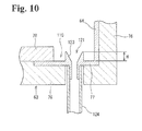
- FIG. 10 is a cross sectional view on the B-B arrow line in FIG. 6 .
- a cylindrical preventer 123 is formed on the circumferential edge of the second drain hole 121, and protrudes upward from the bottom surface of the second circumferential channel 110.
- the preventer 123 has an apex height H that is lower than the top surface of the heat transfer layer 78.
- the second drain hole 121 is connected to a third drain pipe 124. When an amount of condensation water is collected in the second circumferential channel 110 that exceeds the preventer 123, the condensation water overflows the preventer 123 and is naturally discharged from the second drain hole 121 to the outside.
- the forced air fan 88 generates an airflow that flows from top to bottom
- an airflow also may be generated that flows from bottom to top.
- the flow of the air below the first and second reagent container tables 21 and 22 also may flow inward in the radial direction toward the center axis O of the circumferential wall 64 of the housing 20.
- the upright wall member 81 also may be provided so as to contact the inner surface of the circumferential wall 64 of the housing 20, and also may be detached from the heat transfer layer 78.
- the upright wall member 81 also may be inclined so that the top part is positioned at the outside in the radial direction, thereby increasing the effect of changing the direction of the airflow.
- the first member of the present invention is configured by the circumferential wall 64 of the housing 20 of the reagent refrigerator 10 in the above embodiment
- the first member may be configured by a low thermal conductivity member that is separate from the circumferential wall 64, for example, a member arranged along the inner side of the circumferential wall 64.
- the circumferential wall 64 may be formed of a high thermal conductivity material such as metal. It is preferable that the first member is configured by the circumferential wall 64 of the housing 20 as in the above embodiment because the first member reduces the space for placement of the reagent container 300 within the housing 20 when the first member is configured by a member that is separate from the circumferential wall 64.
- the first member and the second member of the present invention are not limited to provision extending the entirety of the housing 20, inasmuch as the first and second members also may be provided at intervals or provided intermittently. Particularly the first member also may be provided in a part allowing easy touching of the reagent container 300 when setting the reagent container 300 in the housing 20.
- the part of the circumferential wall 64 of the housing 200 that is exposed when the movable cover 68 of the cover 66 is opened may be formed of low thermal conductivity material, while the other parts (parts normally hidden by the cover 66) are formed of high thermal conductivity material.
- the first member and the second member of the present invention also may both be configured by the circumferential wall 64.
- the part of the circumferential wall 64 above the top surface of the first and second reagent container tables 21 and 22 may be formed by a low thermally conductive material, and the part below the top surface of the first and second reagent container tables 21 and 22 may be formed of high thermally conductive material.
- the transport drive unit also may relatively rotate both reagent container tables 21 and 22 by rotating one or another of the first reagent container table 21 and the second reagent container table 22.
Landscapes
- Physics & Mathematics (AREA)
- Health & Medical Sciences (AREA)
- Life Sciences & Earth Sciences (AREA)
- Chemical & Material Sciences (AREA)
- Analytical Chemistry (AREA)
- Biochemistry (AREA)
- General Health & Medical Sciences (AREA)
- General Physics & Mathematics (AREA)
- Immunology (AREA)
- Pathology (AREA)
- Automatic Analysis And Handling Materials Therefor (AREA)
Abstract
Description
- The present invention relates to a specimen analyzer for analyzing a sample using a cooled reagent.
- There are known specimen analyzers provided with a reagent refrigerator for cooling reagent within an accommodated reagent container, wherein the specimen analyzer analyzes specimens using the reagent cooled within a reagent refrigerator (for example,
U.S. Patent Application Publication No. 2009/0004057 ). The reagent refrigerator disclosed inU.S. Patent Application Publication No. 2009/0004057 is configured to accommodate a reagent container within a reagent case that is cooled by Peltier element, and cool the reagent within the reagent container by circulating the air within the reagent case via a circulation unit, the reagent case being formed of a material that has excellent thermal conductivity, such as aluminum or the like. - The reagent refrigerator disclosed in
U.S. Patent Application Publication No. 2009/0004057 readily generates condensation, particularly in the reagent case, because the reagent case has high thermal conductivity and is cooled by a Peltier element. Hence, when the user sets a reagent container in the reagent case, there is concern that the reagent container may come into contact with the side walls and the like of the reagent case causing condensation water to adhere to the reagent container. Condensation water adhering to the reagent container may interfere with the reading of the barcode label adhered to the reagent container, and there is further concern that condensation water may penetrate into the reagent container. - In view of the aforesaid information, an object of the present invention is to provide a specimen analyzer capable of inhibiting adhesion of condensation water on the reagent container when the reagent container is set in the reagent refrigerator.
- The scope of the present invention is defined solely by the appended claims, and is not affected to any degree by the statements within this summary.
-
- (1) According to a first aspect of the present invention, a specimen analyzer comprising:
- a reagent refrigerator configured to store and cool a reagent container; a measurement unit configured to measure a specimen by using a reagent in the reagent container cooled by the reagent refrigerator; wherein the reagent refrigerator comprises: a housing configured so that an upper portion of the housing is openable and closable> a reagent container table configured so that the reagent container is set thereon, wherein
- the reagent container table is arranged within the housing so as to space away from a bottom of the housing; a first member arranged so as to face a side surface of the reagent container set on the reagent container table; and a second member arranged lower than the reagent container table, wherein the second member has a higher thermal conductivity than that of the first member.
-
- (2) The specimen analyzer of (1), wherein the first member is arranged along the outer periphery of the reagent container table.
- (3) The specimen analyzer of (1) or (2), wherein the first member configures at least a side wall of the housing above the reagent container table.
-
- (4) The specimen analyzer of any one of (1) through (3), wherein the reagent refrigerator has a cooling unit for cooling the air within the housing; and the cooling unit contacts at least part of the second member.
-
- (5) The specimen analyzer of (4), wherein the reagent refrigerator has a fan unit for circulating the air cooled by the cooling unit within the housing.
-
- (6) The specimen analyzer of claim 5, wherein the fan unit moves the air downward from above the reagent container table; and at least part of the second member is shaped to direct the air supplied from the fan unit upward from below the reagent container table.
-
- (7) The specimen analyzer of any one of (1) through (6), wherein the second member comprises an upright wall member in the peripheral direction along the inner side of the side wall of the housing.
-
- (8) The specimen analyzer of (7), wherein the upright wall member is arranged to open a space from a side wall of the housing.
-
- (9) The specimen analyzer of (7) or (8), wherein the second member configures the bottom of the housing and comprises a bottom wall member connected to the upright wall member.
-
- (10) The specimen analyzer of any one of (1) through (9), wherein at least part of the reagent container table is formed by a member that has lower thermal conductivity than the second member.
- (11) The specimen analyzer of any one of (1) through (10), wherein the first member is made of synthetic resin and the second member is made of metal.
- (12) The specimen analyzer of any one of (1) through (11), further comprising: a channel for collecting condensation water adhered to the second member; and a water discharge device for discharging the water collected in the channel.
According to (12), adhesion of moisture, such as condensation leaking form the housing, on the drive unit can be prevented. - (13) The specimen analyzer of (12), wherein the channel is provided in the bottom surface of the second member; and the water discharge channel is provided in the channel.
- (14) The specimen analyzer of any one of (1) through (13), further comprising a drive unit for driving the rotation of the reagent container table, wherein the drive unit is arranged outside the housing in a region other than below the housing.
- (15) The specimen analyzer of (14), comprising a power transmission unit, a part of which extends through the housing, to transmit the power of the drive unit to the reagent container table; and a chamber for preserving airtightness of a space within the housing, and accommodating at least one of part of the power transmission unit and part of the drive unit connected to part of the power transmission unit.
- (16) The specimen analyzer of any one of (1) through (3), wherein the reagent container table comprises: container a first reagent table with an outer peripheral edge part, arranged to open a space above the bottom part of the housing within the housing; an annular second reagent container table with an inner peripheral edge part, arranged on the outer periphery of the first reagent container table to open a space above the bottom part of the housing within the housing, wherein the specimen analyzer comprises: a drive unit for driving the relative rotations of the first reagent container table and the second reagent container table; a cooling unit for cooling the air within the housing; and a fan unit for circulating the air cooled by the cooling unit within the housing, wherein the outer peripheral edge part of the first reagent container table and the inner peripheral edge part of the second reagent container table are arranged so as to overlap in a vertical direction.
- (17) The specimen analyzer of (16), wherein the top surface of the reagent container of the first reagent container table and the top surface of the reagent container of the second reagent container table are arranged at identical heights.
- (18) The specimen analyzer of (16) or (17), wherein the first reagent container table and the second reagent container table are not in mutual contact.
- (19) The specimen analyzer of any one of (16) through (18), wherein with respect to the direction of airflow below the first reagent container table and the second reagent container table, the edge part of one of the reagent container tables positioned on the upstream side is arranged to be lower than the edge part of the other reagent container table positioned on the downstream side.
- According to the present invention, adhesion of condensation water on the reagent container can be prevented when the reagent container is set within the reagent refrigerator.
-
-
FIG. 1 is a perspective view showing the general structure of a specimen analyzer of an embodiment of the present invention; -
FIG. 2 is a brief structural view of the specimen analyzer ofFIG. 1 ; -
FIG. 3 is a brief plan view showing the reagent refrigerator and dispenser unit; -
FIG. 4 is a brief plan view showing top surface of the housing in an opened condition; -
FIG. 5 is a side cross sectional view briefly showing the reagent refrigerator ofFIG. 1 ; -
FIG. 6 is a horizontal cross sectional view of the inner bottom surface of the reagent refrigerator viewed from above; -
FIG. 7 is a side cross sectional view briefly showing the enlarged essential parts within the reagent refrigerator; -
FIG. 8 is a plan view showing part of the upright wall member; -
FIG. 9 is a cross sectional view on the A-A arrow line inFIG. 6 . -
FIG. 10 is a cross sectional view on the B-B arrow line inFIG. 6 . - The embodiments of the specimen analyzer of the present invention are described in detail hereinafter with reference to the accompanying drawings.
FIG. 1 is a perspective view showing the general structure of a specimen analyzer 1 of an embodiment of the present invention. - The specimen analyzer 1 is an apparatus for performing specific measurements of a measurement sample prepared by mixing a reagent and a specimen collected from a human body, then analyzing the specimen based on the measurement results, and is, for example, a blood coagulation measuring apparatus, immunoanalyzer, or biochemical analyzer. The specimen analyzer 1 is configured by a measuring
device 2, and acontrol device 4 that is electrically connected to themeasuring device 2. Provided within a casing 5 of the measuringdevice 2 is areagent refrigerator 10 for accommodating and cooling a plurality of reagent containers which hold reagent. The casing 5 of the measuringdevice 2 has acover body 5A that can be opened and closed; at least part of thereagent refrigerator 10 can be exposed by opening thecover body 5A. -
FIG. 2 is a brief structural view of the specimen analyzer 1 fFIG. 1 . The measuringdevice 2 of the specimen analyzer 1 is provided with, in addition to thereagent refrigerator 10, aspecimen supply unit 12,transport drive unit 13, dispensingsection 14, measuringunit 15,reader 33, andcontrol circuit 16. Thespecimen supply unit 12 has the function of setting a specimen rack that holds specimen containers (test tubes or the like) containing a specimen, and positioning each specimen container at a predetermined dispensing position by transporting the specimen rack. Thetransport drive unit 13 has the function of transporting the reagent container accommodated in thereagent refrigerator 10 to the predetermined dispensing position. - The dispensing
section 14 has the function of dispensing specimen and reagent from the specimen container and reagent container positioned at the predetermined dispensing positions to prepare a measurement sample.FIG. 3 is a plan view showing thereagent refrigerator 10 and the dispensingsection 14. As shown inFIG. 3 , the dispensingsection 14 has a plurality of dispensingunits 25 through 29; each dispensingunit 25 through 29 is capable of dispensing reagent from within the reagent container accommodated in thereagent refrigerator 10. - When describing a
single dispensing unit 25 by way of example, the dispensingunit 25 has asupport 25a, anarm 25b wherein the base end is supported by thesupport 25a, and apipette 25c provided at the tip of thearm 25b. Thearm 25b is driven to pivot on the base end to rotate in horizontal directions and is further driven to ascend and descent in vertical directions. Thepipette 25c is inserted into anaspiration hole 71 formed in the top surface of thereagent refrigerator 10, and aspirates reagent from the reagent container 300 (refer toFIG. 5 ) within thereagent refrigerator 10 via the horizontal rotation and vertical elevator action of thearm 25b. Theother dispensing units 26 through 29 have structures identical to that of the dispensingunit 25, and their detailed description is therefore omitted. - As shown in
FIG. 2 , the measuringunit 15 has the function of performing specific measurements of the measurement sample prepared by mixing a specimen and reagent. Thereader 33 is a barcode reader for reading a barcode adhered to thereagent container racks 310 and 320 (refer toFIG. 5 ) that accommodate thereagent container 300, and thereagent container 300 accommodated in thereagent refrigerator 10. As shown inFIG. 5 , thereagent container 300 has aside surface 300a. The barcode is adhered to theside surface 300a. Thereader 33 is disposed outside thereagent refrigerator 10, and is capable of reading a barcode within thereagent refrigerator 10 through a slit (not shown in the drawing) which is formed in thereagent refrigerator 10 and is opened and closed via a shutter. - As shown in
FIG. 2 , thecontrol circuit 16 has a CPU, memory such as RAM, ROM or the like, and a communication interface; thecontrol circuit 16 has the function of controlling the operations of thereagent refrigerator 10,transport drive unit 13, dispensingunit 14, measuringunit 15, andreader 33, and transmitting and receiving various types of information to/from the control device , to which thecontrol circuit 16 is connected so as to be capable of communication. - As shown in
FIG. 1 , thecontrol device 4 is a personal computer 401 (PC), and includes acontroller 4a,display 4b, and keyboard 4c for inputting information. Thecontroller 4a has the functions of transmitting an operation start signal of the measuringdevice 2 to thecontrol circuit 16 of the measuringdevice 2, and analyzing the information of the measurement result obtained by the measuringdevice 2. Thedisplay 4b has the function of displaying the analysis result obtained by thecontroller 4a. -
FIG. 5 is a side sectional view briefly showing thereagent refrigerator 10.
Thereagent refrigerator 10 is provided to refrigerate thereagent container 300 containing a reagent to be added to a specimen, and transport thereagent container 300 in a rotational direction around an axis O. The reagent is prevented from degenerating by being preserved at low temperature. Thereagent refrigerator 10 is provided with ahousing 20, and reagent container tables 21 and 22 arranged within thehousing 20 and loaded withreagent containers 300 containing reagent. - The reagent container tables 21 and 22 are configured by annular first reagent table 21, and an annular reagent container table 22 arranged concentrically with the first reagent container table 21 and on the outer side in the diameter direction of the first reagent container table 21. The first reagent container table 21 and the second reagent container table 22 are arranged so that the first
reagent container rack 310 and the secondreagent container rack 320 holding a plurality ofreagent containers 300 are respectively detachable. - The first reagent container table 21 and the second reagent container table 22 are respectively and independently rotatable in both clockwise and counterclockwise directions on the axis O via the
transport drive unit 13. Hence, thereagent containers 300 set on the reagent container tables 21 and 22 are transported in rotational directions. Eachreagent container 300 is positioned at the dispensing position of the dispensingunits 25 through 29 by transporting thereagent container 300 in a rotational direction. Details of the structure of thetransport drive unit 13 are described later. - As shown in
FIG. 5 , thereagent refrigerator 10 and thehousing 20 are provided with a solid-bottom cylindrical shapedmain body 65 with abottom wall 63 forming the bottom part of thehousing 20 and a circumferential wall (side wall) 64 rising from the periphery of abottom wall 63, and acover 66 that functions as a top wall of thereagent refrigerator 10 by closing the top opening of themain body 65. The sealed space circumscribed by themain body 65 and thecover 66 is a refrigeration chamber, and the plurality ofreagent containers 300 set in the reagent container tables 21 and 22 within the refrigeration chamber are enclosed completely therein on the outside in the diameter direction (outside in the horizontal direction) by thecircumferential wall 64. - As shown in
FIG. 3 , thecover 66 is configured by a fixedcover 67 that closes approximately the back half of themain body 65, and amovable cover 68 that closes the approximate front half of themain body 65 and is openable. Themovable cover 68 is coupled to the front edge of the fixedcover 67 so as to oscillate through ahinge member 69. - The
cover 66 of thehousing 20 has a plurality of aspiration holes 71 formed therein; these aspiration holes 71 are configured so that thepipette 25c of the dispensingunits 25 through 29 can be inserted, and the reagent within thereagent container 300 held in thereagent refrigerator 10 can be aspirated from the top opening of thereagent container 300. - Note that exchanging the reagent in the
reagent refrigerator 10 is accomplished for eachreagent container rack cover 5A (refer toFIG. 1 ) of the measuringdevice 2 to expose the front side of thereagent refrigerator 10, opening themovable cover 68 upward to open the front half of thereagent refrigerator 10.FIG. 4 is a plan view of the reagent refrigerator showing thecover 66 in the open condition. When thecover 66 is open, the interior of themain body 65 is exposed, and the reagent racks 310 and 320 holding thereagent containers 300 can be inserted into themain body 65 and removed from themain body 65. - As shown in
FIG. 5 , the circumferential wall (side wall) 64 of themain body 65 of thehousing 20 is formed of a material having low thermal conductivity. Thebottom wall 63 has different material for theouter part 77 and theheat transfer layer 78; theouter part 77 is formed of the same low thermal conductivity material as thecircumferential wall 64 and is linked to the bottom end of thecircumferential wall 64. - The
heat transfer layer 78 of thebottom wall 63 is formed of a material that has a higher thermal conductivity than thecircumferential wall 64 and theouter part 77, and protrudes upward from theouter part 77. Thecircumferential wall 64,bottom wall 63, andouter part 77 of themain body 65 may be formed of thermoplastic resin such as ABS and the like. Theheat transfer layer 78 may be formed of a metal such as aluminum, iron, steel and the like. The outer surface of thecircumferential wall 64 and thebottom wall 63 are covered by thermal shield layers 76 and 79 that have lower thermal conductivity. -
FIG. 6 is a horizontal cross sectional view of the inner bottom surface of thereagent refrigerator 10 viewed from above. As shown inFIG. 6 , theheat transfer layer 78 provided on thebottom wall 63 of thehousing 20 is formed in a polygonal shape (hexagonal shape in the example of the drawing) in the plan view. As shown inFIGS. 5 and6 . part of the bottom surface of theheat transfer layer 78 is exposed below, and a cooler 80 is provided on this exposed surface. In the present embodiment, twocoolers 80 are arranged at symmetrical positions centered on the central axis O of the reagent refrigerator 10 (that is, the center of rotation of the first and second reagent container tables 21 and 22). The cooler 80 is configured to cool the air within thereagent refrigerator 10 using theheat transfer layer 78 as a cooling medium by directly cooling theheat transfer layer 78 which has a high thermal conductivity. Note that the cooler 80 is not limited to using a Peltier element, and also may provide cooling, for example, by air cooling or water cooling theheat transfer layer 78. The planar shape of theheat transfer layer 78 is not limited a polygonal shape, and also may be circular. - An
upright wall member 81 is provided in the circumferential direction along thecircumferential wall 64 on the inside of thecircumferential wall 64 of themain body 65. As shown inFIG. 5 , theupright wall member 81 is positioned below the top surface of the first and second reagent container tables 21 and 22, and is separated form the inner surface of thecircumferential wall 64 at the inner side of thecircumferential wall 64. As shown inFIG. 6 , theupright wall member 81 is formed with an approximately circular shape in the plan view, and extends the approximate entire circumference of thehousing 20. Note that theupright wall member 81 of the present embodiment has an approximately circular shape by curving a band-like plate in a polygonal shape. - A mounting
part 81a that protrudes inward in the diameter direction is provided at the bottom end of theupright wall member 81, and theupright wall member 81 is connected to theheat transfer layer 78 by the mountingpart 81a being screwed to the top surface of theheat transfer layer 78. Theupright wall member 81 is formed of metal, for example, aluminum, that is a material that has the same high thermal conductivity as theheat transfer layer 78. Theupright wall member 81 connected to theheat transfer layer 78 and is cooled by the cooler 80. - A heat sink (condensation promoting member) 82 is provided on the top surface of the
heat transfer layer 78. Theheat sink 82 is formed of a material having a high thermal conductivity such as aluminum, and increases the surface area by having a plurality of protuberances or fins. As shown inFIG. 6 , the heat sinks 82 are respectively provided positions above the twocoolers 80, and are cooled by thecoolers 80 through theheat transfer layer 78. Note that theheat transfer layer 78,upright wall member 81, andheat sink 82 configure the "second member" in the present embodiment. - As shown in
FIG. 5 , in thereagent refrigerator 10, acylindrical ventilation body 21d stands in the center of the first reagent container table 21, and a forced air fan (fan unit) 88 is provided within theventilation body 21d. The forcedair fan 88 is configured to blow the air taken in from above theventilation body 21d downward in theventilation body 21d, theventilation body 21d being the air flow pass. The airflow produced by the forcedair fan 88 therefore blows on theheat transfer layer 78 that is directly cooled by the cooler 80. The airflow is thus effectively cooled. - The airflow produced by the forced
air fan 88 flows outward in the radial direction after striking theheat transfer layer 78, and changes direction upward after striking theupright wall member 81, so that the air flows between the circumferential wall 64 (inside surface) of thereagent refrigerator 10 and the second reagent container table 22 and upward above the second reagent container table 22. Thereafter, the air flows in an inward radial direction along the bottom surface of thecover 66, and is taken into the top of the forcedair body 21d so as to be once again blown downward by the forcedair fan 88, hence, circulating the air within thereagent refrigerator 10. The reagent in thereagent container 300 placed in the first and second reagent container tables 21 and 22 is cooled to a desired temperature, for example, approximately 10□, by the air circulated by the forcedair fan 88. - Condensation is facilitated by the
heat transfer layer 78,upright wall member 81, andheat sink 82 because the high thermal conductivityheat transfer layer 78,upright wall member 81, andheat sink 82 are exposed in the region below the top surfaces of the first and second reagent container tables 21 and 22 and theheat transfer layer 78,upright wall member 81, andheat sink 82 are cooled by thecoolers 80. On the other hand, condensation is inhibited mainly because the low thermal conductivity circumferential wall 64 (first member in the present invention) is arranged in the region above the top surfaces of the first and second reagent container tables 21 and 22. - Accordingly, condensation is produced solely below the top surface of the first and second reagent container tables 21 and 22 and condensation is inhibited above the top surface of the first and second reagent container tables 21 and 22 even though warm outside air flows into the
housing 20 when themovable cover 68 of thecover 66 is opened and a reagent container 30 is set inside thehousing 20. Therefore, condensation water is prevented from adhering to thereagent container 300 even when thereagent container 300 comes into contact with thecircumferential wall 64 while being set within thehousing 20. The problem of condensation water adhering to thereagent container 300 and, for example, the problems of condensation water penetrating into thereagent container 300 and adversely affecting the reading of the barcode adhered on thereagent container 300 are likewise avoided. - The
circumferential wall 64 is directly cooled by theupright wall member 81 which is cooled by the cooler 80 since theupright wall member 81 is arranged a distance from the inner surface of thecircumferential wall 64 on the inner side of thecircumferential wall 64 of thehousing 20. Thecircumferential wall 64 is therefore not overly cooled, and the formation of condensation on thecircumferential wall 64 is inhibited.
Theupright wall member 81 is formed in a polygonal shape in plan view. As shown inFIG. 8 , the airflow at the inner surface of theupright wall member 81 is directed toward acorner angle 81b of theupright wall member 81, which changes the direction upward. Hence, theupright wall member 81 functions to direct the flow of the air upward. The air is effectively cooled since the airflow is within the entire inner surface of theupright wall member 81, which is cooled by the cooler 80. - A cover heater 95 (refer to
FIG. 5 ) is provided inside thecover 66, and thecover 66 is warmed by thecover heater 95. Specifically, as shown inFIGS. 3 and5 , achannel 72, which extends along the movement track of thearm 25b of the dispensingunits 25 through 29, is formed in the top surface of thecover 66, and an aspiratinghole 71 is formed in thechannel 72. Thecover 66 becomes thin in the part of thechannel 72, and is therefore easily cooled by the cool air in thehousing 20 so that external air readily condenses. Condensation formation is prevented in thechannel 72 and penetration of condensation water into thehousing 20 from the aspiratinghole 71 is prevented by providing thecover heater 95 inside thecover 66 in the region of thechannel 72. - As shown in
FIG. 5 , the first and second reagent container tables 21 and 22 are driven in rotation by thetransport drive unit 13. Specifically, thetransport drive unit 13 has afirst drive body 97 and asecond drive body 98 configured by stepper motors or the like. The first andsecond drive bodies housing 20, and a re connected to the first and second reagent container tables 21 and 22 through apower transmission device 99. Thepower transmission device 99 is configured by a first drivenpulley 100, second drivenpulley 101,first drive pulley 102,second drive pulley 103,first transmission belt 104, andsecond transmission belt 105. The first drivenpulley 100 and the second drivenpulley 101 are arranged on the center axis O of thereagent refrigerator 10, and are supported by the bottom part of thehousing 20 so as to be relatively mutually rotatable. The first reagent container table 21 is connected to the first drivenpulley 100, and the second reagent container table 22 is connected to the second drivenpulley 101. - The first driven
pulley 102 is mounted on the output shaft of thefirst drive body 97, and thesecond drive pulley 103 is mounted on the output shaft of thesecond drive body 98. Thefirst drive belt 104 is reeved around the first drivenpulley 100 and thefirst drive pulley 102, and thesecond drive belt 105 is reeved around the second drivenpulley 101 and thesecond drive pulley 103. Therefore, the first reagent container table 21 can be rotated through thefirst drive pulley 102,first transmission belt 104, and first drivenpulley 100 by operating thefirst drive body 97; the second reagent container table 22 can be rotated through thesecond drive pulley 103,first transmission belt 105, and second drivenpulley 101 by operating thesecond drive body 98. - A
first insertion opening 107 and a second insertion opening 108 are formed in thecircumferential wall 64 of thehousing 20 for the firstdrive transmission belt 104 and the seconddrive transmission belt 105 to pass through. At the side of thereagent refrigerator 10 is formed achamber 109 to maintain airtightness and that is circumscribed by a heat insulating material; thereceptacle 109 is connected to thereagent refrigerator 10 through thefirst insertion opening 107 and thesecond insertion opening 108. Part of the drive shafts of the first andsecond drive bodies second transmission belts chamber 109. Therefore, since cool air is prevented within thechamber 109 even though the cool air within thehousing 20 leaks from the first andsecond insertion openings housing 20. - Since the
first drive body 97 and thesecond drive body 98 are arranged at the side of thereagent refrigerator 10, condensation does not adhere to thefirst drive body 97 and thesecond drive body 98 even when condensation water formed within thereagent refrigerator 10 spreads downward from thereagent refrigerator 10, hence damage to thefirst drive body 97 and thesecond drive body 98 is prevented. - Note that the
first drive body 97 and thesecond drive body 98 are not limited to the side of thereagent refrigerator 10, and may be arranged anywhere, even outside thereagent refrigerator 10, with the exclusion of below thereagent refrigerator 10. Although thepower transmission device 99 is a transmission device employing drive belts reeved on pulleys, the present invention is not limited to this arrangement inasmuch as other drive transmission device also may be used, such as a gear transmission device. -
FIG. 7 is a side cross sectional view briefly showing the enlarged essential parts within thereagent refrigerator 10.
As shown inFIG. 10 , the first reagent container table 21 has afirst placement part 21a with atop surface 21h for setting areagent container 300, and afirst support part 21b for supporting thefirst placement part 21a from the bottom side; the center part of thefirst support part 21b is connected to the first drivenpulley 100 so as to be integratedly rotatable. A plurality offirst openings 21c are formed with spacing in the circumferential direction from the center (region below the forced air fan 88) of thefirst support part 21b, and air flows vertically through thefirst openings 21c. The outer circumference end of thefirst support part 21b is positioned outside in the radial direction from the outer circumference end of thefirst placement part 21a, and aconcave step part 21e is formed in an approximate L-shape at the top surface side of the circumferential edge of the first reagent container table 21. - The second reagent container table 22 has a
second placement part 22a with atop surface 22h for setting areagent container 300, and asecond support part 22b for supporting thesecond placement part 22a from the bottom side; the center part of thesecond support part 22b is connected to the second drivenpulley 101 so as to be integratedly rotatable. A plurality ofsecond openings 22c are formed with spacing in the circumferential direction of thesecond support part 22b, and air flows vertically through thesecond openings 22c.
Note that in the present embodiment, thefirst placement part 21a of the first reagent container table 21 is made of synthetic resin such as ABS or the like, and thesecond placement part 22a of the second reagent container table 22 is made of metal such as aluminum or the like. Alternatively, thefirst placement part 21a of the first reagent container table 21 may be made of metal, and thesecond placement part 22a of the second reagent container table 22 may be made of synthetic resin, or both may be made of synthetic resin or of metal. From the perspective of inhibiting formation of condensation, theplacement parts - The outer peripheral edge of the first reagent container table 21, that is, the outer circumferential edge of the
first support part 22b, is arranged to be outside in the radial direction from the inner peripheral edge of the second reagent container table 22, that is, the inner circumferential edge of thesecond placement part 22a. Thus, the outer peripheral edge of the first reagent container table 21 and the inner peripheral edge of the second reagent container table 22 overlap in a vertical direction so that no space occurs between the tables 21 and 22 in the plan view. The dimension of the overlap of the tables 21 and 22 is designated t. - The outer peripheral edge of the first reagent container table 21 is arranged on the bottom side of the inner peripheral edge of the second reagent container table 22. That is, when the airflow direction C below the first and second reagent container tables 21 and 22 is set as standard, the outer peripheral edge of the first reagent container table 21 positioned upstream of the airflow direction C is disposed below the inner peripheral edge of the second reagent container table 22 positioned on the downstream side. Therefore, the air flowing below the first and second reagent container tables 21 and 22 is unlikely to escape upward through the gap of the first and second reagent container tables 21 and 22. Below the first and second reagent container tables 21 and 22, an airflow can be reliably produced from the center of the
housing 20 to thecircumferential wall 64 of thehousing 20, thus suitably producing circulating air within thehousing 20. - The inner peripheral edge of the second reagent container table 22 is arranged to fit into the
step part 21e of the first reagent container table 21, so that the top surface of the first reagent container table 21 and the top surface of the second reagent container table 22 are mutually at the same height. Thus, the heights of thereagent containers 300 of both reagent container tables 21 and 22 are the same, and the elevator strokes of thepipette 25c in the dispensingunits 25 through 29 (refer toFIG. 3 ) are uniform when aspirating reagent from thereagent container 300. Operational control of the dispensingunits 25 through 29 is therefore simplified. Moreover, there is no contact between the outer peripheral edge of the first reagent container table 21 and the inner peripheral edge of the second reagent container table 22, and both tables 21 and 22 can rotate smoothly with little rotational friction even without a gap between the tables 21 and 22 in the plan view. - As shown in
FIG. 6 , an annular firstcircumferential channel 135 is formed in the outer circumferential side of theheat transfer layer 78 provided on thebottom wall 63 of thehousing 20. The firstcircumferential channel 135 has the function of collecting condensation water formed by theheat transfer layer 78. The firstcircumferential channel 135 is polygonal in shape (hexagonal in the example of the drawing) in plan view similar to theheat transfer layer 78. Afirst drain hole 136 is formed in the bottom surface of the firstcircumferential channel 135. -
FIG. 9 is a cross sectional view on the A-A arrow line inFIG. 6 . Thefirst drain hole 136 is connected to afirst drain pipe 137. The condensation water collected in the firstcircumferential channel 135 is discharged from thefirst drain hole 136 by periodically operating a pump (not shown in the drawing) that is connected to thefirst drain pipe 137. - As shown in
FIG. 6 , since theheat transfer layer 78 provided on thebottom wall 63 of thereagent refrigerator 10 is formed higher than the outer peripheral part in the outside radial direction, a secondcircumferential channel 110 is formed in the bottom surface of the outercircumferential part 77 between theheat transfer layer 78 and thecircumferential wall 64. The secondcircumferential channel 110 is positioned below theupright wall member 81. Accordingly, the condensation water formed on theupright wall member 81 and the condensation water formed on the outer circumferential part of theheat transfer layer 78 is mainly collected in the secondcircumferential channel 110. - A
second drain hole 121 and athird drain hole 131 are formed in the secondcircumferential channel 110. As shown inFIG. 9 , thethird drain hole 131 is formed flush with the bottom surface (top surface of the outer circumferential part 77) of the secondcircumferential channel 110, and athird drain pipe 132 is connected to thethird drain hole 131. The condensation water collected in the secondcircumferential channel 110 is discharge from thethird drain hole 131 by periodically operating a pump (not shown in the drawing) connected to thethird drain pipe 132. -
FIG. 10 is a cross sectional view on the B-B arrow line inFIG. 6 . Acylindrical preventer 123 is formed on the circumferential edge of thesecond drain hole 121, and protrudes upward from the bottom surface of the secondcircumferential channel 110. Thepreventer 123 has an apex height H that is lower than the top surface of theheat transfer layer 78. Thesecond drain hole 121 is connected to athird drain pipe 124. When an amount of condensation water is collected in the secondcircumferential channel 110 that exceeds thepreventer 123, the condensation water overflows thepreventer 123 and is naturally discharged from thesecond drain hole 121 to the outside. - The present invention is not limited to the above embodiment and may be variously modified insofar as such modifications are within the scope of the claims.
- For example, although the forced
air fan 88 generates an airflow that flows from top to bottom, an airflow also may be generated that flows from bottom to top. The flow of the air below the first and second reagent container tables 21 and 22 also may flow inward in the radial direction toward the center axis O of thecircumferential wall 64 of thehousing 20. - The
upright wall member 81 also may be provided so as to contact the inner surface of thecircumferential wall 64 of thehousing 20, and also may be detached from theheat transfer layer 78. Theupright wall member 81 also may be inclined so that the top part is positioned at the outside in the radial direction, thereby increasing the effect of changing the direction of the airflow. - Although the first member of the present invention is configured by the
circumferential wall 64 of thehousing 20 of thereagent refrigerator 10 in the above embodiment, the first member may be configured by a low thermal conductivity member that is separate from thecircumferential wall 64, for example, a member arranged along the inner side of thecircumferential wall 64. In this case, thecircumferential wall 64 may be formed of a high thermal conductivity material such as metal. It is preferable that the first member is configured by thecircumferential wall 64 of thehousing 20 as in the above embodiment because the first member reduces the space for placement of thereagent container 300 within thehousing 20 when the first member is configured by a member that is separate from thecircumferential wall 64. - The first member and the second member of the present invention are not limited to provision extending the entirety of the
housing 20, inasmuch as the first and second members also may be provided at intervals or provided intermittently. Particularly the first member also may be provided in a part allowing easy touching of thereagent container 300 when setting thereagent container 300 in thehousing 20. For example, as shown inFIG. 4 , only the part of thecircumferential wall 64 of the housing 200 that is exposed when themovable cover 68 of thecover 66 is opened may be formed of low thermal conductivity material, while the other parts (parts normally hidden by the cover 66) are formed of high thermal conductivity material. - The first member and the second member of the present invention also may both be configured by the
circumferential wall 64. In this case, the part of thecircumferential wall 64 above the top surface of the first and second reagent container tables 21 and 22 may be formed by a low thermally conductive material, and the part below the top surface of the first and second reagent container tables 21 and 22 may be formed of high thermally conductive material. - The transport drive unit also may relatively rotate both reagent container tables 21 and 22 by rotating one or another of the first reagent container table 21 and the second reagent container table 22.
Claims (19)
- A specimen analyzer comprising:a reagent refrigerator configured to store and cool a reagent container;a measurement unit configured to measure a specimen by using a reagent in the reagent container cooled by the reagent refrigerator; whereinthe reagent refrigerator comprises:a housing configured so that an upper portion of the housing is openable and closable;a reagent container table configured so that the reagent container is set thereon, wherein the reagent container table is arranged within the housing so as to space away from a bottom of the housing;a first member arranged so as to face a side surface of the reagent container set on the reagent container table; anda second member arranged lower than the reagent container table, wherein the second member has a higher thermal conductivity than that of the first member.
- The specimen analyzer of claim 1, wherein
the first member is arranged along the outer periphery of the reagent container table. - The specimen analyzer of claim 1 or 2, wherein
the first member configures at least a side wall of the housing above the reagent container table. - The specimen analyzer of any one of claims 1 through 3, wherein
the reagent refrigerator has a cooling unit for cooling the air within the housing; and the cooling unit contacts at least part of the second member. - The specimen analyzer of claim 4, wherein
the reagent refrigerator has a fan unit for circulating the air cooled by the cooling unit within the housing. - The specimen analyzer of claim 5, wherein
the fan unit moves the air downward from above the reagent container table; and
at least part of the second member is shaped to direct the air supplied from the fan unit upward from below the reagent container table. - The specimen analyzer of any one of claims 1 through 6, wherein
the second member comprises an upright wall member in the peripheral direction along the inner side of the side wall of the housing. - The specimen analyzer of claim 7, wherein
the upright wall member is arranged to open a space from a side wall of the housing. - The specimen analyzer of claim 7 or 8, wherein
the second member configures the bottom of the housing and comprises a bottom wall member connected to the upright wall member. - The specimen analyzer of any one of claims 1 through 9, wherein
at least part of the reagent container table is formed by a member that has lower thermal conductivity than the second member. - The specimen analyzer of any one of claims 1 through 10, wherein
the first member is made of synthetic resin and the second member is made of metal. - The specimen analyzer of any one of claims 1 through 11, further comprising:a channel for collecting condensation water adhered to the second member; anda water discharge device for discharging the water collected in the channel.
- The specimen analyzer of claim 12, wherein
the channel is provided in the bottom surface of the second member; and
the water discharge channel is provided in the channel. - The specimen analyzer of any one of claims 1 through 13, further comprising a drive unit for driving the rotation of the reagent container table, wherein
the drive unit is arranged outside the housing in a region other than below the housing. - The specimen analyzer of claim 14, comprising
a power transmission unit, a part of which extends through the housing, to transmit the power of the drive unit to the reagent container table; and
a chamber for preserving airtightness of a space within the housing, and accommodating at least one of part of the power transmission unit and part of the drive unit connected to part of the power transmission unit. - The specimen analyzer of any one of claims 1 through 3, wherein
the reagent container table comprises:container a first reagent table with an outer peripheral edge part, arranged to open a space above the bottom part of the housing within the housing;an annular second reagent container table with an inner peripheral edge part, arranged on the outer periphery of the first reagent container table to open a space above the bottom part of the housing within the housing, whereinthe specimen analyzer comprises:whereina drive unit for driving the relative rotations of the first reagent container table and the second reagent container table;a cooling unit for cooling the air within the housing; anda fan unit for circulating the air cooled by the cooling unit within the housing,the outer peripheral edge part of the first reagent container table and the inner peripheral edge part of the second reagent container table are arranged so as to overlap in a vertical direction. - The specimen analyzer of claim 16, wherein
the top surface of the reagent container of the first reagent container table and the top surface of the reagent container of the second reagent container table are arranged at identical heights. - The specimen analyzer of claim 16 or 17, wherein
the first reagent container table and the second reagent container table are not in mutual contact. - The specimen analyzer of any one of claims 16 through 18, wherein
with respect to the direction of airflow below the first reagent container table and the second reagent container table, the edge part of one of the reagent container tables positioned on the upstream side is arranged to be lower than the edge part of the other reagent container table positioned on the downstream side.
Applications Claiming Priority (2)
| Application Number | Priority Date | Filing Date | Title |
|---|---|---|---|
| JP2011058481A JP5752449B2 (en) | 2011-03-16 | 2011-03-16 | Sample analyzer |
| JP2011058480A JP5753713B2 (en) | 2011-03-16 | 2011-03-16 | Sample analyzer |
Publications (2)
| Publication Number | Publication Date |
|---|---|
| EP2500732A2 true EP2500732A2 (en) | 2012-09-19 |
| EP2500732A3 EP2500732A3 (en) | 2016-05-04 |
Family
ID=45954322
Family Applications (1)
| Application Number | Title | Priority Date | Filing Date |
|---|---|---|---|
| EP12159459.2A Withdrawn EP2500732A3 (en) | 2011-03-16 | 2012-03-14 | Specimen analyzer |
Country Status (3)
| Country | Link |
|---|---|
| US (1) | US8999241B2 (en) |
| EP (1) | EP2500732A3 (en) |
| CN (1) | CN102680719B (en) |
Cited By (2)
| Publication number | Priority date | Publication date | Assignee | Title |
|---|---|---|---|---|
| GB2539192A (en) * | 2015-06-05 | 2016-12-14 | Stratec Biomedical Ag | Device, system and method for cooling a reagent compartment |
| CN111630393A (en) * | 2018-01-25 | 2020-09-04 | 希森美康株式会社 | Sample measuring device and method for circulating air in reagent store |
Families Citing this family (19)
| Publication number | Priority date | Publication date | Assignee | Title |
|---|---|---|---|---|
| USD787695S1 (en) * | 2014-09-05 | 2017-05-23 | Siemens Healthcare Diagnostics Products Gmbh | Blood testing apparatus |
| WO2016130962A1 (en) | 2015-02-13 | 2016-08-18 | Abbott Laboratories | Automated storage modules for diagnostic analyzer liquids and related systems and methods |
| CN104678117B (en) * | 2015-02-15 | 2018-01-16 | 石家庄禾柏生物技术股份有限公司 | A kind of temperature automatically controlled integrated quantitative sampling reagent adding device detector |
| WO2016143085A1 (en) * | 2015-03-11 | 2016-09-15 | 株式会社島津製作所 | Autosampler |
| JP6467047B2 (en) * | 2015-06-17 | 2019-02-06 | 株式会社日立ハイテクノロジーズ | Automatic analyzer |
| CN105137105B (en) * | 2015-08-28 | 2017-08-15 | 深圳市锦瑞生物科技有限公司 | A kind of Miniature biochemical analysis instrument |
| CN108885221A (en) | 2016-03-28 | 2018-11-23 | 株式会社日立高新技术 | Automatic analysing apparatus |
| CN105759066B (en) * | 2016-04-26 | 2018-05-22 | 绍兴普施康生物科技有限公司 | Full automatic blood-coagulation detection analysis instrument, method |
| CN108152521A (en) * | 2016-12-05 | 2018-06-12 | 深圳华大智造科技有限公司 | Reagent storing device |
| WO2019142343A1 (en) * | 2018-01-22 | 2019-07-25 | 株式会社島津製作所 | Sample temperature adjustment device |
| JP6959875B2 (en) | 2018-01-25 | 2021-11-05 | シスメックス株式会社 | Specimen measuring device, reagent container and sample measuring method |
| CN108226462A (en) * | 2018-03-05 | 2018-06-29 | 苏州长光华医生物医学工程有限公司 | A kind of immunity analysis instrument agent bin of good refrigeration effect |
| CN109188009B (en) * | 2018-10-26 | 2023-12-26 | 苏州长光华医生物医学工程有限公司 | Reagent storehouse structure |
| CN113646640B (en) | 2019-04-18 | 2025-02-25 | 株式会社日立高新技术 | Automatic analyzer, reagent cold storage in automatic analyzer, and reagent cold storage method |
| JP7414954B2 (en) * | 2020-03-11 | 2024-01-16 | 株式会社日立ハイテク | automatic analyzer |
| JP7426904B2 (en) | 2020-06-01 | 2024-02-02 | 株式会社日立ハイテク | automatic analyzer |
| JP7229975B2 (en) * | 2020-08-07 | 2023-02-28 | 日本電子株式会社 | Automated analyzer and cold storage |
| JP7504742B2 (en) * | 2020-09-29 | 2024-06-24 | キヤノンメディカルシステムズ株式会社 | Reagent storage and automatic analyzer |
| USD1035035S1 (en) * | 2022-11-11 | 2024-07-09 | Biosys Usa Llc | Biochemical analyzer |
Citations (2)
| Publication number | Priority date | Publication date | Assignee | Title |
|---|---|---|---|---|
| JPH02184345A (en) * | 1989-01-10 | 1990-07-18 | Nippon Tectron Co Ltd | Temperature controller for reagent bottle table |
| US20090004057A1 (en) | 2007-06-29 | 2009-01-01 | Naoto Sato | Automatic analyzer and reagent storage thereof |
Family Cites Families (6)
| Publication number | Priority date | Publication date | Assignee | Title |
|---|---|---|---|---|
| JPH0634932B2 (en) * | 1987-04-06 | 1994-05-11 | 日本テクトロン株式会社 | Temperature control structure for reagent bottle table |
| FR2801107B1 (en) * | 1999-11-16 | 2002-03-01 | Maxmat S A | BIOMEDICAL ANALYZER WITH TOTAL IDENTIFICATION OF SAMPLE TUBES AND REAGENTS OF A STORAGE MODULE |
| WO2005008219A2 (en) | 2003-07-18 | 2005-01-27 | Bio-Rad Laboratories, Inc. | System and method for multi-analyte detection |
| JP2009139269A (en) * | 2007-12-07 | 2009-06-25 | Hitachi High-Technologies Corp | Automatic analyzer |
| JP2010237021A (en) * | 2009-03-31 | 2010-10-21 | Sysmex Corp | Analyzer |
| JP5432779B2 (en) * | 2010-03-12 | 2014-03-05 | シスメックス株式会社 | Analysis equipment |
-
2012
- 2012-03-12 US US13/417,897 patent/US8999241B2/en active Active
- 2012-03-14 EP EP12159459.2A patent/EP2500732A3/en not_active Withdrawn
- 2012-03-15 CN CN201210067917.4A patent/CN102680719B/en active Active
Patent Citations (2)
| Publication number | Priority date | Publication date | Assignee | Title |
|---|---|---|---|---|
| JPH02184345A (en) * | 1989-01-10 | 1990-07-18 | Nippon Tectron Co Ltd | Temperature controller for reagent bottle table |
| US20090004057A1 (en) | 2007-06-29 | 2009-01-01 | Naoto Sato | Automatic analyzer and reagent storage thereof |
Cited By (5)
| Publication number | Priority date | Publication date | Assignee | Title |
|---|---|---|---|---|
| GB2539192A (en) * | 2015-06-05 | 2016-12-14 | Stratec Biomedical Ag | Device, system and method for cooling a reagent compartment |
| US10335794B2 (en) | 2015-06-05 | 2019-07-02 | Stratec Se | Device, system and method for cooling a reagent compartment |
| CN111630393A (en) * | 2018-01-25 | 2020-09-04 | 希森美康株式会社 | Sample measuring device and method for circulating air in reagent store |
| EP3745135A4 (en) * | 2018-01-25 | 2021-11-17 | Sysmex Corporation | SAMPLE MEASURING DEVICE AND METHOD OF CIRCULATING AIR IN THE STORAGE OF REAGENTS |
| US11994527B2 (en) | 2018-01-25 | 2024-05-28 | Sysmex Corporation | Sample measuring apparatus and method of circulating air in reagent storage |
Also Published As
| Publication number | Publication date |
|---|---|
| US8999241B2 (en) | 2015-04-07 |
| CN102680719A (en) | 2012-09-19 |
| CN102680719B (en) | 2015-08-05 |
| US20120237398A1 (en) | 2012-09-20 |
| EP2500732A3 (en) | 2016-05-04 |
Similar Documents
| Publication | Publication Date | Title |
|---|---|---|
| US8999241B2 (en) | Specimen analyzer | |
| JP5753713B2 (en) | Sample analyzer | |
| JP5634856B2 (en) | Reagent cold storage and sample analyzer equipped with the same | |
| CN107636470B (en) | Automatic analyzer | |
| US20110223064A1 (en) | Sample analyzer | |
| JP2012194072A (en) | Specimen analysis apparatus | |
| JP2013185980A (en) | Automatic analyzer | |
| JP7140545B2 (en) | Reagent storage and automatic analyzer | |
| JP2009270857A (en) | Automatic analyzer | |
| JP2023181437A (en) | automatic analyzer | |
| JP2016114610A (en) | Automatic analyzer | |
| JP6416673B2 (en) | Automatic analyzer | |
| CN113646640B (en) | Automatic analyzer, reagent cold storage in automatic analyzer, and reagent cold storage method | |
| JP5680383B2 (en) | Automatic analyzer | |
| JP6858037B2 (en) | Reagent cold insulation device, automatic analyzer and cold insulation system | |
| US12064770B2 (en) | Reagent storage and automatic analyzing apparatus | |
| JP2025075089A (en) | How to dry the reagent cooler | |
| JP2012145449A (en) | Specimen analyzer | |
| JP2006058212A (en) | Dispensing table equipped with heat-retaining function | |
| JP7332769B2 (en) | Reagent storage and automatic analyzer | |
| CN1795389B (en) | Used in the temperature control system in the automatic bioanalyzer | |
| JP7789223B2 (en) | automatic analyzer | |
| JP2002014107A (en) | Cooler for automatic biochemical analyzer | |
| JP2011117802A (en) | Automatic analyzer | |
| US20090232707A1 (en) | Apparatus for examining bodily fluids |
Legal Events
| Date | Code | Title | Description |
|---|---|---|---|
| PUAI | Public reference made under article 153(3) epc to a published international application that has entered the european phase |
Free format text: ORIGINAL CODE: 0009012 |
|
| AK | Designated contracting states |
Kind code of ref document: A2 Designated state(s): AL AT BE BG CH CY CZ DE DK EE ES FI FR GB GR HR HU IE IS IT LI LT LU LV MC MK MT NL NO PL PT RO RS SE SI SK SM TR |
|
| AX | Request for extension of the european patent |
Extension state: BA ME |
|
| PUAL | Search report despatched |
Free format text: ORIGINAL CODE: 0009013 |
|
| AK | Designated contracting states |
Kind code of ref document: A3 Designated state(s): AL AT BE BG CH CY CZ DE DK EE ES FI FR GB GR HR HU IE IS IT LI LT LU LV MC MK MT NL NO PL PT RO RS SE SI SK SM TR |
|
| AX | Request for extension of the european patent |
Extension state: BA ME |
|
| RIC1 | Information provided on ipc code assigned before grant |
Ipc: G01N 35/04 20060101ALI20160329BHEP Ipc: G01N 35/00 20060101AFI20160329BHEP |
|
| 17P | Request for examination filed |
Effective date: 20161024 |
|
| RBV | Designated contracting states (corrected) |
Designated state(s): AL AT BE BG CH CY CZ DE DK EE ES FI FR GB GR HR HU IE IS IT LI LT LU LV MC MK MT NL NO PL PT RO RS SE SI SK SM TR |
|
| STAA | Information on the status of an ep patent application or granted ep patent |
Free format text: STATUS: EXAMINATION IS IN PROGRESS |
|
| 17Q | First examination report despatched |
Effective date: 20200803 |
|
| STAA | Information on the status of an ep patent application or granted ep patent |
Free format text: STATUS: THE APPLICATION IS DEEMED TO BE WITHDRAWN |
|
| 18D | Application deemed to be withdrawn |
Effective date: 20240628 |