EP2500576A1 - Heat circulation pump - Google Patents
Heat circulation pump Download PDFInfo
- Publication number
- EP2500576A1 EP2500576A1 EP11002072A EP11002072A EP2500576A1 EP 2500576 A1 EP2500576 A1 EP 2500576A1 EP 11002072 A EP11002072 A EP 11002072A EP 11002072 A EP11002072 A EP 11002072A EP 2500576 A1 EP2500576 A1 EP 2500576A1
- Authority
- EP
- European Patent Office
- Prior art keywords
- terminal box
- motor
- motor housing
- plug
- circulation pump
- Prior art date
- Legal status (The legal status is an assumption and is not a legal conclusion. Google has not performed a legal analysis and makes no representation as to the accuracy of the status listed.)
- Granted
Links
Images

Classifications
-
- H—ELECTRICITY
- H02—GENERATION; CONVERSION OR DISTRIBUTION OF ELECTRIC POWER
- H02K—DYNAMO-ELECTRIC MACHINES
- H02K5/00—Casings; Enclosures; Supports
- H02K5/04—Casings or enclosures characterised by the shape, form or construction thereof
- H02K5/22—Auxiliary parts of casings not covered by groups H02K5/06-H02K5/20, e.g. shaped to form connection boxes or terminal boxes
- H02K5/225—Terminal boxes or connection arrangements
-
- F—MECHANICAL ENGINEERING; LIGHTING; HEATING; WEAPONS; BLASTING
- F04—POSITIVE - DISPLACEMENT MACHINES FOR LIQUIDS; PUMPS FOR LIQUIDS OR ELASTIC FLUIDS
- F04D—NON-POSITIVE-DISPLACEMENT PUMPS
- F04D13/00—Pumping installations or systems
- F04D13/02—Units comprising pumps and their driving means
- F04D13/06—Units comprising pumps and their driving means the pump being electrically driven
- F04D13/0606—Canned motor pumps
- F04D13/0626—Details of the can
-
- F—MECHANICAL ENGINEERING; LIGHTING; HEATING; WEAPONS; BLASTING
- F04—POSITIVE - DISPLACEMENT MACHINES FOR LIQUIDS; PUMPS FOR LIQUIDS OR ELASTIC FLUIDS
- F04D—NON-POSITIVE-DISPLACEMENT PUMPS
- F04D13/00—Pumping installations or systems
- F04D13/02—Units comprising pumps and their driving means
- F04D13/06—Units comprising pumps and their driving means the pump being electrically driven
- F04D13/0686—Mechanical details of the pump control unit
-
- F—MECHANICAL ENGINEERING; LIGHTING; HEATING; WEAPONS; BLASTING
- F04—POSITIVE - DISPLACEMENT MACHINES FOR LIQUIDS; PUMPS FOR LIQUIDS OR ELASTIC FLUIDS
- F04D—NON-POSITIVE-DISPLACEMENT PUMPS
- F04D13/00—Pumping installations or systems
- F04D13/02—Units comprising pumps and their driving means
- F04D13/06—Units comprising pumps and their driving means the pump being electrically driven
- F04D13/0693—Details or arrangements of the wiring
-
- F—MECHANICAL ENGINEERING; LIGHTING; HEATING; WEAPONS; BLASTING
- F04—POSITIVE - DISPLACEMENT MACHINES FOR LIQUIDS; PUMPS FOR LIQUIDS OR ELASTIC FLUIDS
- F04D—NON-POSITIVE-DISPLACEMENT PUMPS
- F04D29/00—Details, component parts, or accessories
- F04D29/02—Selection of particular materials
- F04D29/026—Selection of particular materials especially adapted for liquid pumps
-
- F—MECHANICAL ENGINEERING; LIGHTING; HEATING; WEAPONS; BLASTING
- F04—POSITIVE - DISPLACEMENT MACHINES FOR LIQUIDS; PUMPS FOR LIQUIDS OR ELASTIC FLUIDS
- F04D—NON-POSITIVE-DISPLACEMENT PUMPS
- F04D29/00—Details, component parts, or accessories
- F04D29/40—Casings; Connections of working fluid
- F04D29/42—Casings; Connections of working fluid for radial or helico-centrifugal pumps
- F04D29/426—Casings; Connections of working fluid for radial or helico-centrifugal pumps especially adapted for liquid pumps
-
- F—MECHANICAL ENGINEERING; LIGHTING; HEATING; WEAPONS; BLASTING
- F04—POSITIVE - DISPLACEMENT MACHINES FOR LIQUIDS; PUMPS FOR LIQUIDS OR ELASTIC FLUIDS
- F04D—NON-POSITIVE-DISPLACEMENT PUMPS
- F04D29/00—Details, component parts, or accessories
- F04D29/58—Cooling; Heating; Diminishing heat transfer
- F04D29/586—Cooling; Heating; Diminishing heat transfer specially adapted for liquid pumps
- F04D29/5893—Cooling; Heating; Diminishing heat transfer specially adapted for liquid pumps heat insulation or conduction
-
- H—ELECTRICITY
- H02—GENERATION; CONVERSION OR DISTRIBUTION OF ELECTRIC POWER
- H02K—DYNAMO-ELECTRIC MACHINES
- H02K11/00—Structural association of dynamo-electric machines with electric components or with devices for shielding, monitoring or protection
- H02K11/30—Structural association with control circuits or drive circuits
- H02K11/33—Drive circuits, e.g. power electronics
-
- H—ELECTRICITY
- H02—GENERATION; CONVERSION OR DISTRIBUTION OF ELECTRIC POWER
- H02K—DYNAMO-ELECTRIC MACHINES
- H02K5/00—Casings; Enclosures; Supports
- H02K5/04—Casings or enclosures characterised by the shape, form or construction thereof
- H02K5/10—Casings or enclosures characterised by the shape, form or construction thereof with arrangements for protection from ingress, e.g. water or fingers
-
- H—ELECTRICITY
- H02—GENERATION; CONVERSION OR DISTRIBUTION OF ELECTRIC POWER
- H02K—DYNAMO-ELECTRIC MACHINES
- H02K5/00—Casings; Enclosures; Supports
- H02K5/04—Casings or enclosures characterised by the shape, form or construction thereof
- H02K5/12—Casings or enclosures characterised by the shape, form or construction thereof specially adapted for operating in liquid or gas
- H02K5/128—Casings or enclosures characterised by the shape, form or construction thereof specially adapted for operating in liquid or gas using air-gap sleeves or air-gap discs
-
- H—ELECTRICITY
- H02—GENERATION; CONVERSION OR DISTRIBUTION OF ELECTRIC POWER
- H02K—DYNAMO-ELECTRIC MACHINES
- H02K7/00—Arrangements for handling mechanical energy structurally associated with dynamo-electric machines, e.g. structural association with mechanical driving motors or auxiliary dynamo-electric machines
- H02K7/14—Structural association with mechanical loads, e.g. with hand-held machine tools or fans
Landscapes
- Engineering & Computer Science (AREA)
- Mechanical Engineering (AREA)
- General Engineering & Computer Science (AREA)
- Power Engineering (AREA)
- Microelectronics & Electronic Packaging (AREA)
- Physics & Mathematics (AREA)
- Thermal Sciences (AREA)
- Structures Of Non-Positive Displacement Pumps (AREA)
- Motor Or Generator Frames (AREA)
Abstract
Description
Die Erfindung betrifft eine Heizungsumwälzpumpe mit den im Oberbegriff des Anspruchs 1 angegebenen Merkmalen.The invention relates to a heating circulation pump with the features specified in the preamble of claim 1.
Derartige Heizungsumwälzpumpen zählen zum Stand der Technik. Sie weisen typischerweise ein Pumpengehäuse mit einem Saug- und einem Druckstutzen sowie ein darin angeordnetes Pumpenlaufrad auf. Zum Antrieb des Pumpenlaufrads ist ein Elektromotor vorgesehen, dessen Welle das Pumpenlaufrad trägt. Der den Rotor umgebende Stator ist in einem Gehäuse angeordnet, welches an seiner zum Pumpengehäuse weisenden Seite einen Flansch oder dergleichen Anschlusselement aufweist, über den das Motorgehäuse, insbesondere das Statorgehäuse mit dem Pumpengehäuse verbunden ist. Zum elektrischen Anschluss des Motors ist ein Klemmenkasten vorgesehen, welcher an der vom Pumpengehäuse abgewandten Axialseite des Statorgehäuses angeordnet ist. Der Klemmenkasten umfasst typischerweise auch die Motorelektronik, also beispielsweise einen Frequenzumrichter. Eine Heizungspumpe der vorgenannten Art ist beispielsweise aus
Derartige Heizungsumwälzpumpen kleiner und mittlerer Bauart werden in Großserien hergestellt, weshalb auch kleinste Verbesserungen schon große Einsparungen bei Fertigung und/oder Montage bedeuten können. Es ist ein stetes Bestreben diese Pumpen einerseits technisch weiter zu verbessern und noch zuverlässiger zu gestalten andererseits die Herstellungs- und Montagekosten zu senken.Such heating circulation pumps of small and medium design are produced in large series, which is why even the smallest improvements can mean significant savings in production and / or assembly. It is a constant effort on the one hand to further improve these pumps technically and even more reliable on the other hand to reduce the manufacturing and assembly costs.
Diese Aufgabe wird gemäß der Erfindung durch eine Heizungsumwälzpumpe mit den in Anspruch 1 angegebenen Merkmalen gelöst. Vorteilhafte Ausgestaltungen der Erfindung sind in den Unteransprüchen der nachfolgenden Beschreibung und der Zeichnung angegeben.This object is achieved according to the invention by a heating circulation pump having the features specified in claim 1. Advantageous embodiments of the invention are specified in the subclaims of the following description and the drawing.
Die erfindungsgemäße Heizungsumwälzpumpe weist ein Pumpengehäuse mit darin angeordnetem Pumpenlaufrad auf, das von einem Elektromotor angetrieben ist, der in einem mit dem Pumpengehäuse verbundenen Motorgehäuse angeordnet ist. Am Motorgehäuse ist ein Klemmenkasten aus Kunststoff befestigt, der zur Aufnahme von elektrischen und/oder elektronischen Bauteilen der Motorsteuerung sowie zum elektrischen Anschluss des Motors vorgesehen und ausgebildet ist. Am Motorgehäuse ist weiterhin ein Erdungskontakt angeordnet. Außen am Klemmenkasten ist ein Stecker oder eine Muffe einer elektrischen Steckverbindung angeordnet, die zum elektrischen Anschluss des Motors bzw. der vorgeschalteten Motorelektronik vorgesehen ist. Dabei ist der Erdungskontakt am Motorgehäuse elektrisch leitend mit einem Erdungskontakt des Steckers oder der Muffe sowie mit mindestens einem Leiter im Inneren des Klemmenkastens verbunden. Gemäß der Erfindung ist die elektrische Verbindung zwischen dem am Motorgehäuse angeordneten Erdungskontakt und dem Erdungskontakt des Steckers oder der Muffe außerhalb des Klemmenkastens angeordnet.The heating circulation pump according to the invention has a pump housing with a pump impeller arranged therein, which is driven by an electric motor which is arranged in a motor housing connected to the pump housing. On the motor housing, a terminal box made of plastic is attached, which is provided and adapted for receiving electrical and / or electronic components of the motor control and for the electrical connection of the motor. On the motor housing a ground contact is still arranged. Outside the terminal box, a plug or a socket of an electrical connector is arranged, which is provided for the electrical connection of the engine or the upstream engine electronics. In this case, the ground contact on the motor housing is electrically connected to a ground contact of the plug or the sleeve and at least one conductor inside the terminal box. According to the invention, the electrical connection between the arranged on the motor housing ground contact and the ground contact of the plug or the sleeve outside the terminal box is arranged.
Grundgedanke der erfindungsgemäßen Lösung ist es, die elektrische Verbindung zwischen dem motorseitigen Erdungskontakt und dem stecker- bzw. muffenseitigen Erdungskontakt außerhalb des Klemmenkastens anzuordnen, um auf diese Weise zu ermöglichen, dass die elektrische Verbindung zwischen dem motorgehäuseseitigen Erdungskontakt und dem stecker- bzw. muffenseitigen Erdungskontakt außerhalb des Klemmenkastens zumindest außerhalb des Inneren des Klemmenkastens geführt werden kann. Eine solche Anordnung hat den Vorteil, dass die sonst beim Stand der Technik einhergehende thermische Kopplung zwischen Motorgehäuse und Klemmenkasten über die Erdung weitgehend vermieden werden kann, was insbesondere dann von Vorteil ist, wenn das Motorgehäuse gegenüber dem Klemmenkasten vergleichsweise warm oder vergleichsweise kalt ist.The basic idea of the solution according to the invention is to arrange the electrical connection between the motor-side ground contact and the plug or socket-side ground contact outside the terminal box, in order in this way to enable the electrical connection between the motor-housing-side ground contact and the plug or socket-side ground contact outside the terminal box at least outside the interior of the terminal box can be performed. Such an arrangement has the advantage that the otherwise associated with the prior art thermal coupling between the motor housing and the terminal box on the ground can be largely avoided, which is particularly advantageous if the motor housing relative to the terminal box is relatively warm or relatively cold.
Besonders vorteilhaft ist es dabei, wenn der Erdungskontakt des Steckers oder der Muffe abgezweigt ausgebildet ist, wobei die Abzweigung außerhalb des Klemmenkastens oder innerhalb der Klemmenkastenwandung liegt. Es erfolgt dann zwar nach wie vor eine Verbindung der Erdung mit mindestens einem Leiter in Inneren des Klemmenkastens, typischerweise auf einer darin befindlichen Platine, jedoch ist die elektrische Verbindung zum Stecker oder zur Muffe vom Erdungskotakt derselben quasi unter Umgehung des Klemmenkastens direkt zum Stecker oder der Muffe geführt, die am Klemmenkasten angeformt und zum elektrischen Anschluss vorgesehen ist. Durch die erfindungsgemäße Lösung wird erreicht, dass der Klemmenkasten, insbesondere die darin angeordneten wärmeempfindlichen Bauteile einer geringeren thermischen Belastung ausgesetzt sind, da die Wärmeleitung zwischen dem Motorgehäuse, welches die im Motor entstehende Abwärme ableitet, soweit sie über den Erdungskontakt erfolgt, teilt, sodass nur noch ein Teil der über den Erdungskontakt geführten Wärme in den Klemmenkasten geleitet und bei geeigneter Ausgestaltung ein Großteil dieser Wärme unter Umgehung des Klemmenkastens direkt zum Stecker bzw. zur Muffe geleitet wird. Zwar wird durch diese Wärmeleitung die Erdungsleitung des Anschlusskabels thermisch höher belastet als bei bekannten Lösungen, doch ist dies unproblematisch, da über die Leitungslänge die Wärme in der Regel problemlos abgebaut werden kann. Die vom Motorgehäuse über den Erdungskontakt in den Klemmenkasten eingebrachte Wärme ist jedoch deutlich geringer als bei bekannten Konstruktionen, da durch die Abzweigung außerhalb des Klemmenkastens oder innerhalb der Klemmenkastenwandung auch eine Abzweigung der Wärmeströme erfolgt, sodass bei geeigneter Ausbildung ein Großteil der über den Erdungskontakt geführten Wärme gar nicht erst in den Klemmenkasten gelangt.It is particularly advantageous if the grounding contact of the plug or the sleeve is formed branched off, wherein the branch is outside the terminal box or within the terminal box wall. Although there is still a connection of grounding with at least one conductor in the interior of the terminal box, typically on a board therein, but the electrical connection to the plug or socket of Erdungskotakt same quasi bypassing the terminal box directly to the plug or the Muff led, which is formed on the terminal box and provided for electrical connection. The inventive solution ensures that the terminal box, in particular the heat-sensitive components disposed therein are exposed to a lower thermal load, since the heat conduction between the motor housing, which dissipates the heat generated in the engine, as far as it is done via the ground contact shares so that only a part of the guided via the ground contact heat in the terminal box passed and a suitable design a large part of this heat, bypassing the terminal box is passed directly to the plug or socket. Although the earthing line of the connection cable is thermally charged higher than in known solutions by this heat conduction, but this is not a problem, since the heat can be degraded easily over the line length as a rule. However, the heat introduced by the motor housing via the grounding contact in the terminal box is significantly lower than in known constructions, since by the branch outside the terminal box or within the terminal box wall also a diversion of the heat flows, so if appropriate Training, most of the heat conducted via the earthing contact does not even get into the terminal box.
Ein weiterer Vorteil der erfindungsgemäßen Lösung ist nicht nur bei Seitens des Motors anstehender Wärme sondern auch umgekehrt bei dort anstehender Kälte gegeben, wie es beispielsweise bei einer Kühlmittelpumpe der Fall sein kann. Nun wird durch die erfindungsgemäße Ausbildung erreicht, dass das Klemmenkasteninnere nicht über diesen Erdungskontakt abgekühlt wird, was zu Kondenswasserbildung und Schäden an der Elektronik führen kann.Another advantage of the solution according to the invention is given not only at the side of the engine pending heat but also vice versa there pending cold, as it may be the case for example in a coolant pump. Now is achieved by the inventive design that the terminal box interior is not cooled via this grounding contact, which can lead to condensation and damage to the electronics.
Wenn die Abzweigung in der Klemmenkastenwandung liegt, ist diese vorteilhaft in einer Seitenwand oder im Boden des Klemmenkastens vorgesehen.If the branch lies in the terminal box wall, this is advantageously provided in a side wall or in the bottom of the terminal box.
Um den Wärmestrom in den Klemmenkasten durch den Erdungskontakt möglichst klein zu halten, ist gemäß der Erfindung vorgesehen, dass der in das Innere des Klemmenkastens führende Teil des Kontaktes einen kleinere Querschnitt als der zum Stecker oder zur Muffe führende Teil hat. Entsprechend der Querschnittsabmessungen erfolgt auch eine Aufteilung der Wärmeströme, sodass bei geeigneter Dimensionierung ein Großteil des vom Motorgehäuse an den Erdungskontakt abgegebenen Wärmestroms nicht in den Klemmenkasten sondern an diesem vorbei zum Stecker bzw. zur Muffe hin gelangt und dort an das Anschlusskabel und an die Außenumgebung abgeleitet werden kann.In order to keep the heat flow in the terminal box through the ground contact as small as possible, it is provided according to the invention that the leading into the interior of the terminal box part of the contact has a smaller cross-section than the part leading to the plug or sleeve. Corresponding to the cross-sectional dimensions, the heat flows are also distributed, so that with suitable dimensioning, a large part of the heat flow delivered by the motor housing to the ground contact does not pass into the terminal box but past it to the plug or socket, where it is dissipated to the connection cable and to the outside environment can be.
Vorteilhaft ist der Erdungskontakt so ausgebildet und angeordnet, dass er zu zwei Kontaktbeinen abgezweigt ist, von denen ein Bein in das Motorgehäuse eingreift und das andere Bein an der Außenseite des Motorgehäuses mit Abstand dazu angeordnet ist und Teil des Steckers bzw. der Muffe bildet. Bei einer solchen Anordnung kann die Abzweigung außerhalb der Klemmenkastenwandung großflächig vorgesehen sein, was wärmetechnisch besonders günstig ist.Advantageously, the grounding contact is designed and arranged so that it is branched off to two contact legs, one leg of which engages in the motor housing and the other leg is arranged on the outside of the motor housing at a distance therefrom and forms part of the plug or the sleeve. In such an arrangement, the branch be provided over a large area outside the terminal box wall, which is particularly favorable in terms of heat technology.
Vorteilhaft ist der Kontakt, insbesondere der Erdungskontakt als Blechteil ausgebildet, das durch Stanzen gebildet ist. Derartige Kontakte sind kostengünstig herstellbar.Advantageously, the contact, in particular the grounding contact designed as a sheet metal part, which is formed by punching. Such contacts are inexpensive to produce.
Zum Anschluss des Motors sind im Stecker oder in der Muffe zwei oder mehr zueinander elektrisch isolierte Kontakte vorgesehen. Diese sind gemäß einer vorteilhaften Weiterbildung der Erfindung baugleich mit dem Erdungskontakt und mit Abstand zueinander und zum Erdungskontakt angeordnet, wobei die nicht Erdungskontakte auch zum Motorgehäuse hin in Kunststoff eingebettet sind, der einen Teil des Klemmenkastens und/oder des Steckers bzw. der Muffe bildet. Eine solche Ausbildung ist besonders vorteilhaft, da sowohl für den Erdungskontakt als auch für die übrigen Kontakte gleiche Bauteile verwendet werden können, was die Teilevielfalt bei der Herstellung und die Handhabung insbesondere bei der Zuführung der Teile erheblich vereinfacht.To connect the motor two or more mutually electrically isolated contacts are provided in the plug or in the socket. These are arranged according to an advantageous embodiment of the invention identical to the ground contact and at a distance from each other and the ground contact, wherein the non-ground contacts are also embedded in the motor housing in plastic, which forms part of the terminal box and / or the plug or the sleeve. Such a design is particularly advantageous because the same components can be used for both the ground contact and for the other contacts, which greatly simplifies the variety of parts in the manufacture and handling especially in the supply of parts.
Dabei ist es besonders vorteilhaft, wenn der Erdungskontakt motorseitig in einer gegenüber der übrigen Wandung des Motorgehäuses erhabenen Vorsprung oder Erhebung eingreift. Dann nämlich ist neben diesem Vorsprung genügend Freiraum, in dem die übrigen Kontakte mit ihrem dort in Kunststoff eingebetteten Kontakten den erforderlichen Einbauraum finden.It is particularly advantageous if the ground contact engages the motor side in a relation to the other wall of the motor housing raised projection or survey. Then that is in addition to this projection enough space in which to find the remaining contacts with their embedded there in plastic contacts the required installation space.
Besonders vorteilhaft ist es, wenn der Erdungskontakt quer zur Einsteckrichtung mindestens einseitig aufgeweitet ausgebildet ist und zumindest in Höhe des aufgeweiteten Bereichs oder auch darüber hinaus eine Materialausnehmung aufweist. Hierdurch kann eine besonders intensive Kontaktierung mit dem Motorgehäuse hergestellt werden. Dann kann die motorgehäuseseitige Ausnehmung, insbesondere im Vorsprung der Wandung des Motorgehäuses in Steckrichtung des Kontaktes gerade ausgebildet sein, was insbesondere bei metallischen Gehäusen, die in Gusstechnik hergestellt werden, von Vorteil ist. Die Kontaktierung erfolgt dadurch intensiv, dass die Aufweitung größer als die lichte Weite der motorseitigen Ausnehmung ist, also dass der Erdungskontakt in diesem Bereich zumindest elastisch möglicherweise auch plastisch verformt wird. Um genügend Freiraum zur Aufnahme der Materialverformung zu gewährleisten, ist eine Materialausnehmung in Höhe der Aufweitung oder darüber hinaus vorgesehen, beispielsweise durch einen Schlitz oder dergleichen. Auf diese Weise wird eine sichere Kontaktierung zwischen dem Erdungskontakt und dem Motorgehäuse sichergestellt, ohne dass fertigungstechnisch zusätzlicher Bauaufwand erfolgt.It is particularly advantageous if the grounding contact is designed to be widened transversely to the insertion direction at least on one side and has a material recess at least at the level of the widened region or even beyond. As a result, a particularly intensive contact with the motor housing can be produced. Then, the motor housing side recess, in particular in the projection of Wall of the motor housing in the insertion direction of the contact to be straight, which is particularly in metallic housings, which are produced by casting, is advantageous. The contacting takes place intensively in that the widening is greater than the clear width of the motor-side recess, so that the grounding contact in this area is possibly also plastically deformed at least elastically. In order to ensure sufficient space for receiving the material deformation, a material recess in the amount of widening or beyond is provided, for example by a slot or the like. In this way, a secure contact between the grounding contact and the motor housing is ensured without manufacturing engineering additional construction costs.
Insbesondere beim Einsatz hochtourig laufender Permanentmagnetmotoren ist es von Vorteil, wenn der Klemmenkasten an der vom Pumpengehäuse abgewandten Axialseite des Motorgehäuses anschließt, da dann genügend Raum für die Aufnahme der Motorelektronik geschaffen werden kann und zwar im Wesentlichen unabhängig von der radialen und axialen Ausdehnung des Motors, insbesondere des Stators. Bei einer solchen axialen Anordnung des Klemmenkastens, d. h. wenn der Klemmenkasten in Achsrichtung der Motorwelle gesehen auf der von der Pumpe abgewandten Seite des Motorgehäuses angeordnet ist, dann ist es vorteilhaft den Stecker oder die Muffe zum Anschluss an der radialen Außenseite des Motorgehäuses und/oder des Klemmenkastens anzuordnen. Bei der vorgenannten Motorbauart ist der Motor häufig im Vergleich zur Pumpe schlanker ausgebildet. Auch weist die Pumpe Saug- und Druckstutzen auf, die bedingen, dass seitliche Freiräume entstehen, die häufig ungenutzt sind. Es ist daher vorteilhaft, in diesen Bereich den Stecker oder die Muffe anzuordnen, da dies die axiale Baulänge der Pumpe nicht vergrößert und räumlich Bereiche nutzt, die ohnehin gegeben und sonst nicht nutzbar sind. Dabei ist es insbesondere vorteilhaft, den Stecker oder die Muffe versetzt zum Klemmenkasten, vorzugsweise neben dem Motorgehäuse anzuordnen und zwar so, dass die Steckrichtung parallel zur Drehachse von Motor und Pumpe ist. Diese Anordnung hat auch den Vorteil, dass zum Aufstecken des Gegensteckers oder der Gegenmuffe kein zusätzlicher Freiraum benötigt wird, jedenfalls nur geringer radialer Freiraum neben der Heizungsumwälzpumpe, der in der Praxis ohnehin frei bleibt und ungenutzt ist.In particular, when using high-speed permanent magnet motors, it is advantageous if the terminal box connects to the axial side facing away from the pump housing axial side of the motor housing, since then sufficient space can be created for receiving the engine electronics and that is substantially independent of the radial and axial extent of the engine, in particular of the stator. In such an axial arrangement of the terminal box, that is, when the terminal box is arranged in the axial direction of the motor shaft on the side facing away from the pump side of the motor housing, it is advantageous for the connector or the sleeve for connection to the radial outside of the motor housing and / or To arrange terminal box. In the aforementioned engine design, the engine is often made slimmer in comparison to the pump. Also, the pump has suction and discharge nozzles, which cause lateral free spaces, which are often unused. It is therefore advantageous to arrange in this area the plug or the sleeve, as this does not increase the axial length of the pump and spatially uses areas that are given anyway and otherwise unusable. It is particularly advantageous, the plug or the sleeve offset from the terminal box, preferably to be arranged next to the motor housing in such a way that the plugging direction is parallel to the axis of rotation of the motor and pump. This arrangement also has the advantage that no additional clearance is needed for attaching the mating connector or the mating sleeve, at least only small radial clearance in addition to the heating circulation pump, which remains free in practice anyway and is unused.
Dabei ist es vorteilhaft, nicht nur die elektrischen Verbindungen zwischen Klemmenkasten und Motor bzw. zwischen Stecker oder Muffe und Anschlusskabel als Steckverbindung auszubilden, sondern darüber hinaus auch die mechanische Verbindung zwischen Klemmenkasten und Motor und/oder Pumpengehäuse. Dies kann dadurch erfolgen, dass mindestens eine Schnappverbindung zwischen diesen Bauteilen vorgesehen ist, wobei die Fügerichtung der Schnappverbindung mit der Fügerichtung des Erdungskontaktes übereinstimmt. Durch diese erdfindungsgemäße Ausbildung kann der Klemmenkasten werkzeugfrei aufgesteckt werden, wobei gleichzeitig mit Aufsteckung alle erforderlichen elektrischen Verbindungen zwischen Motor und Klemmenkasten geschlossen werden. Eine solche Anordnung ist insbesondere in der Großserienfertigung von Vorteil, da sie die Montage vereinfacht und verbilligt.It is advantageous not only to form the electrical connections between the terminal box and the motor or between the plug or socket and connecting cable as a plug connection, but also the mechanical connection between the terminal box and motor and / or pump housing. This can be done by providing at least one snap connection between these components, wherein the joining direction of the snap connection coincides with the joining direction of the grounding contact. By this Erddfindungsgemäße training of the terminal box can be attached without tools, while at the same time all necessary electrical connections between the motor and terminal box are closed with attachment. Such an arrangement is particularly advantageous in mass production because it simplifies assembly and cheaper.
Vorteilhaft ist der Klemmenkasten so ausgebildet, dass er hermetisch gegenüber der Umgebung und auch gegenüber dem Motor abgedichtet ist. Dabei erfolgt die Abdichtung gegenüber den herauszuführenden elektrischen Kontakten zweckmäßigerweise durch Eingießen derselben in die Klemmenkastenwandung.Advantageously, the terminal box is designed so that it is hermetically sealed from the environment and also with respect to the engine. The seal against the herauszuführenden electrical contacts is advantageously carried out by pouring the same in the terminal box wall.
Da der Klemmenkasten vor dem hermetischen Verschließen die elektrischen elektronischen Bauteile aufnehmen muss, ist es zweckmäßig, diesen nach Art eines konventionellen Klemmenkastens aus zwei Bauteilen aufzubauen, so beispielsweise einen Klemmenkastengrundkörper mit Deckel. Diese sind dann gemäß einer vorteilhaften Weiterbildung der Erfindung aus thermoplastischem Kunststoff gebildet und durch Schweißen miteinander verbunden. Hierdurch entsteht ein vollständig geschlossener und nach außen hin hermetisch gekapselter Klemmenkasten. Dabei kann die Schweißung vorteilhaft durch Laserschweißen erfolgen, wenn beispielsweise der Deckel aus einem für den Laserstrahl durchgängigen und der Grundkörper aus einem für den Laserstrahl nicht durchgängigen Material gebildet ist. Dann kann die Schweißnaht, was fertigungstechnisch besonders günstig ist, durch den Deckel hindurch in der Trennfuge zwischen Deckel und Grundkörper gebildet werden, indem dort das Material durch den Laserstrahl aufgeschmolzen wird.Since the terminal box must accommodate the electrical electronic components before hermetically closing, it is expedient to build this in the manner of a conventional terminal box of two components, such as a terminal box body with Cover. These are then formed according to an advantageous embodiment of the invention made of thermoplastic material and joined together by welding. This creates a completely closed and hermetically sealed terminal box to the outside. In this case, the welding can be advantageously carried out by laser welding, for example, if the cover is formed from a continuous for the laser beam and the base body of a non-continuous for the laser beam material. Then, the weld, which is particularly favorable in terms of manufacturing technology, can be formed through the cover in the parting line between the cover and the base body, where the material is melted by the laser beam.
Die Erfindung ist nachfolgend anhand von in der Zeichnung dargestellten Ausführungsbeispielen näher erläutert. Es zeigen:
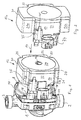
- Fig. 1
- in vereinfachter perspektivischer Darstellung eine Heizungsumwälzpumpe gemäß der Erfindung,
- Fig. 2
- einen Klemmenkasten mit radialen Erweiterungen in Darstellung entsprechend
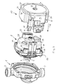
Fig. 1 , - Fig.3
- in perspektivischer Explosionsdarstellung Pumpe, Motor und Klemmenkasten,
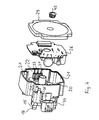
- Fig. 4
- in perspektivischer Explosionsdarstellung den Klemmenkasten gemäß
Fig. 3 in seinem Aufbau, - Fig. 5
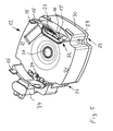
- eine perspektivische Ansicht des Klemmenkastens von unten,
- Fig. 6
- eine perspektivische Längsschnittdarstellung von Klemmenkasten und Motor mit angesetztem Pumpenlaufrad,
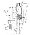
- Fig. 7
- in vergrößerter Darstellung einen Längsschnitt im Bereich des Erdungskontaktes zwischen Klemmenkasten und Motor und
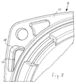
- Fig. 8
- in vergrößerter Darstellung eine Ansicht auf den Eckbereich des Motorgehäuseflansches von der Pumpenseite.
- Fig. 1
- in a simplified perspective view of a heating circulation pump according to the invention,
- Fig. 2
- a terminal box with radial extensions in illustration accordingly
Fig. 1 . - Figure 3
- in perspective exploded view pump, motor and terminal box,
- Fig. 4
- in a perspective exploded view of the terminal box according to
Fig. 3 in its construction, - Fig. 5
- a perspective view of the terminal box from below,
- Fig. 6
- a perspective longitudinal sectional view of the terminal box and motor with attached pump impeller,
- Fig. 7
- in an enlarged view a longitudinal section in the region of the ground contact between the terminal box and motor and
- Fig. 8
- in an enlarged view, a view of the corner region of the motor housing flange from the pump side.
Die anhand der
Die Heizungsumwälzpumpe weist weiterhin einen Motor auf, hier einem Nasslaufmotor, dessen Rotor 6 in einem Spaltrohr 7 läuft, das flüssigkeitsgefüllt ist. Umgeben wird das Spaltrohr 7 von einem Stator, d. h. von den umfangsseitig um das Spaltrohr 7 angeordneten Motorwicklungen, sowie einem Motorgehäuse 8, welches den Stator aufnimmt. Der Rotor 6 weist eine zentrale Welle 9 auf, die sich bis in das Pumpengehäuse 1 erstreckt und das Pumpenlaufrad 5 trägt, sodass die Drehbewegung des Rotors 6 auf das Pumpenlaufrad 5 übertragen wird.The heating circulation pump further has a motor, here a wet-running motor, the rotor 6 runs in a
Das Motorgehäuse 8 weist an seiner zum Pumpengehäuse 1 weisenden Seite einen Flansch 10 auf, mit dem es an das Pumpengehäuse 1 angeschlossen und über vier Schrauben 11 in den Eckbereichen des Flansches mit dem Pumpengehäuse 1 dicht und fest verbunden ist. In der dargestellten Ausführungsform bestehen Pumpengehäuse 1 und Motorgehäuse 8 aus Metall und sind als Gussteile gefertigt.The
Bei den hier dargestellten Heizungsumwälzpumpen ist das Motorgehäuse 8 als metallisches Gussgehäuse ausgebildet. Für die vorliegende Erfindung kann das Gehäuse jedoch auch durch einen vergossenen Stator gebildet werden, wie dies dann der Fall ist, wenn die Statorwicklung in Kunststoff eingegossen ist. Auch kann das Motorgehäuse als Kunststoffspritzgussteil ausgebildet sein. Es versteht sich, dass dann der weiter unten im Einzelnen beschriebene Erdungskontakt gesondert innerhalb des Kunststoffes eingegliedert ist und elektrisch leitend mit dem Statorblechpaket und dem dann metallisch ausgebildeten Spaltrohr des Motors verbunden ist.In the case of the heating circulation pumps shown here, the
Die Heizungsumwälzpumpe weist weiterhin einen Klemmenkasten 12 auf, der aus Kunststoff besteht und an der vom Pumpengehäuse 1 abgewandten Axialseite des Motorgehäuses 8 angebracht ist und das Motorgehäuse 8 zu seiner Axialseite vollständig und radial, d. h. umfangsseitig, teilweise übergreift.The heating circulation pump further has a
Die vorstehend und nachstehend aufgeführten Raumbezeichnungen axial und radial beziehen sich auf die Drehachse 13 des Rotors 6 bzw. des Pumpenlaufrades 5. Die Axialseiten sind also die Seiten, die zur Drehachse 13 im Wesentlichen senkrecht verlaufen, wohingegen Radialflächen die Flächen sind, welche sich parallel zur Drehachse erstrecken.The axial and radial space designations mentioned above and below relate to the axis of
Das Motorgehäuse 8 weist im Flanschbereich einen abgerundeten im Wesentlichen quadratischen Querschnitt auf, wohingegen der übrige Teil des Motorgehäuses 8, also der sich zum Klemmenkasten 12 anschließende Teil im Wesentlichen einen kreisrunden Querschnitt aufweist und daher eine zylindermantelförmige Umfangsfläche aufweist. Während Pumpengehäuse 1 und Motorgehäuse 8 mittels vier Schrauben 11 lösbar miteinander verbunden sind, ist der aus Kunststoff bestehende Klemmenkasten 12 am Motorgehäuse 1 durch Schnappverbindungen befestigt. Hierzu weist der Klemmenkasten 12 vier sich aus den Seitenwandungen 14 des Klemmenkastens zum Pumpengehäuse 1 hin erstreckende Zungen 15 auf, an deren Ende seitlich Schnappvorsprünge 16 angeordnet sind, die Schnappausnehmungen 17 im Motorgehäuse 8 hintergreifen, welche am Motorgehäuse 8 im bereich des Flansches 10 angeformt sind. Diese Schnappausnehmungen 17 sind jeweils durch eine Stufe in einer rohrförmigen vom Flansch 10 zum Klemmenkasten 12 weisenden Führung 18 am Motorgehäuse 8 gebildet (siehe
Beim Aufstecken des Klemmenkastens 12 auf das Motorgehäuse 8 in Achsrichtung, also in Aufsteckrichtung 19, gelangen die Zungen 15 in die fluchtend dazu angeordneten Führungen 18, wobei die Schnappvorsprünge 16 durch Querauslenkung der Zungen seitlich nach innen an den die Schnappausnehmungen 17 bildenden Stufen vorbeifahren und nach Überfahren derselben durch elastisches Rückstellen der Zungen 15 nach außen einrasten und damit den Klemmenkasten 12 auf dem Motorgehäuse 8 halten.When attaching the
Der Klemmenkasten 12 hat in Richtung der Drehachse 13 gesehen, eine im Wesentlichen rechteckige Außenkontur und ist in den Eckbereichen, also im Bereich gedachter axialer Verlängerungen der Schrauben 11 ausgespart ausgebildet, damit die Schrauben 11 auch bei aufgesetzten Klemmenkasten 12 für ein aus Axialrichtung aufgesetztes Werkzeug zugänglich sind. Diese Eckausnehmungen sind mit 20 gekennzeichnet.The
Bei dieser Formgebung ergeben sich bei der dargestellten vertikalen Einbaulage (Saugstutzen 2 und Druckstutzen 3 liegen vertikal übereinander) horizontale Randbereiche 21 und vertikale Randbereiche 22 des Klemmenkastens 12.In the case of this shaping,
Die vertikalen Randbereiche 22 werden bei der dargestellten Ausführungsform zur Herausführung elektrischer Kontakte genutzt, wohingegen die horizontalen Randbereich 21 zur Anordnung von Elektronikbauteilen innerhalb des Klemmenkastens genutzt werden. Da baugleiche Pumpen mit Elektromotoren mit unterschiedlicher Motorelektronik ausgestattet werden können, kann, wie beim Vergleich der Darstellung gemäß
In den vertikalen Randbereichen 22 sind die elektrischen Kontakte angeordnet, und zwar in Achsrichtung vom Klemmenkasten 12 in Richtung zum Pumpengehäuse 1 gesehen sind in dem rechten vertikalen Randbereich 22 die zur Motorwicklung führenden Kontakte 23 und im linken vertikalen Randbereich 22 die zu einem Steckanschluss vom elektrischen Anschluss des Motors herausgeführten Kontakte 24 angeordnet. Diese Kontakte 23 und 24 sind in der Schnittdarstellung gemäß
Alle Kontakte 23 und 24 sowie die weiteren an der linken Seite in dem vertikalen Randbereich 22 angeordneten Kontakte 25, welche zur Motorsteuerung dienen, enden im Klemmenkasten 12 an einer Platine 26, die in der Darstellung nach
Die Kontakte 23, 24 und 25 sind dicht in den aus thermoplastischem Kunststoff gebildeten Klemmenkasten 12 eingegossen und zwar die Kontakte 23 in den Boden 27 des Klemmenkastens 12 und die Kontakte 24 und 25 in den Boden 27 bzw. die daran angrenzende Seitenwand 14.The
Der Boden 27 des Klemmenkastens 12 ist vollständig geschlossen ausgebildet und zur Axialwand 28 des Motorgehäuses 8 beabstandet ausgebildet 8 (siehe
Die Schweißnaht 30 ist durch Laserschweißen von der Deckelseite ausgebildet. Hierzu ist der Deckel 29 aus einem für den Laserstrahl durchlässigem Material gefertigt, wohingegen der Grundkörper, also der Boden 27 und die Seitenwände 14, aus einem für den Laserstrahl im Wesentlichen undurchlässigem Material gefertigt sind. Die Schweißung erfolgt der Gestalt, dass der Laserstrahl von der Deckelseite aus auf die zum Deckel weisenden Stirnseiten der Seitenwände 14 gerichtet wird. Dabei gelangt der Laserstrahl durch den für den Laserstrahl durchlässigen Deckel 29 bis zu den Stirnseiten der Seitenwände 14, wo er das Material aufschmilzt, das aufgrund der Wärmeeinwirkung auch mit dem Deckelmaterial verschmilzt und auf diese Weise eine hermetische Schweißverbindung zwischen den Seitenwänden 14 und dem Deckel 29 bildet, wodurch der Klemmenkasten 12 nach außen hin hermetisch abgeschlossen ist. Dabei erfolgt die Verschweißung nicht nur im Bereich der außen liegenden Wände 14 sondern auch im Bereich der zentralen Ausnehmung 31, also an einer sonst zum Schweißen extrem schlecht zugänglichen Stelle.The
Der Klemmenkasten 12 ist durch eine zentrale Ausnehmung 31 durchsetzt, welche in axialer Richtung verläuft, durch einen Stopfen 42 abgeschlossen ist und nicht mit dem Inneren des Klemmenkastens verbunden ist. Diese Ausnehmung 31 führt zu einer ebenfalls mittels einer Schraube verschlossenen Öffnung in der Axialwand 28 des Motorgehäuses 8, über welche das freie Ende der Welle 9 zugänglich ist, um bei einem Blockieren des Rotors 6 diesen von Hand frei drehen zu können. Die diese Öffnung verschließende Schraube ist als eine Art Madenschraube mit Innensechskant ausgebildet, wobei die Innensechskantaufnahme so ausgebildet ist, dass die Schraube beim Entfernen am Werkzeug verbleibt, sodass bei Entfernen des Stopfens 42 mittels eines Schlüssels diese Schraube entfernt und dann mittels eines weiteren Werkzeugs die Welle 9 manuell gedreht werden kann. In umgekehrter Reihenfolge werden die Öffnungen dann wieder verschlossen. Die Ausnehmung 31 durchsetzt den Klemmenkasten 12 also in axialer Richtung, sodass sich ein hermetisch abgeschlossener Ringraum im Klemmenkasten 12 ergibt.The
Soweit es die zur Verbindung mit der Motorwicklung vorgesehenen Kontakte 23 angeht, sind diese nach Art einer Muffe 32 in den Boden des Klemmenkastens 12 und zwar in dem rechten vertikalen Randbereich 22 eingeformt. Am Motorgehäuse 8 ist ein an der Axialwand 28 axial zum Klemmenkasten 12 vorspringender Stecker 33 ausgebildet, welcher beim Aufstecken des Klemmenskastens 12 auf das Motorgehäuse 8 mit der Muffe 32 verbunden wird, worüber die elektrische Verbindung zwischen Klemmenkasten 12 und Motorwicklung hergestellt wird.As far as the
Auf der gegenüberliegenden linken Seite des vertikalen Randbereichs 22 des Klemmenkastens 12 sind die Kontakte 24 mit einem Bein zu einer Muffe 34 und die Kontakte 25 zu einer Muffe 35 herausgeführt. Einer der Kontakte 24, nämlich der in
Die Nichterdungskontakte 24, die von der Formgebung identisch mit dem Erdungskontakt ausgebildet sind, weisen ebenfalls ein Steckteil 36 mit Ausnehmung 37 auf, sind jedoch in dem Bereich des Steckteils 36 von Kunststoff umgossen, motorseitig ist hier ein Freiraum, da die Erhebung 39 quasi punktuell nur im Bereich des Steckteils 36 des Erdungskontaktes vorgesehen.The
Die Kontakte 24 und somit insbesondere auch der Erdungskontakt, der eine innige Verbindung mit dem Motorgehäuse 8 hat, ist in dem Boden 27 bzw. in der Seitenwand 14 zu zwei Beinen abgezweigt ausgebildet (siehe
Die Muffe 35, welche die Kontakte 25 aufnimmt, ist in ähnlicher Weise aus dem Klemmenkasten herausgeführt, jedoch durch die Seitenwand 14. Die dort gebildete Muffe 35 liegt in der Darstellung gemäß
Die Muffen 34 und 35 sind als Flachmuffen ausgebildet, derart, dass ihre Kontakte 24 bzw. 25 jeweils nebeneinander in einer im Wesentlichen parallel zum Motorgehäuse 8 angeordneten Ebene befindlich sind. Durch diese Anordnung ist der radiale Bauraum neben dem Motorgehäuse 8 bzw. Klemmenkasten 12 vergleichsweise klein.The
Wenn das Motorgehäuse nicht als metallisches Gussgehäuse sondern als Kunststoffgehäuse oder als den Stator umgebene Vergussmasse ausgebildet ist, dann ist die Ausnehmung 38 in der Erhebung des Motorgehäuses mit einem Kontakt versehen, beispielsweise durch eine hohlzylindrische metallische Muffe gebildet, die elektrisch leitend mit dem Statorblechpaket und dem metallischen Spaltrohr 7 verbunden ist, um die elektrische Sicherheit der Heizungsumwälzpumpe für den Fall, dass eines dieser Bauteile durch einen Statordefekt Spannung führt, gewährleistet ist.If the motor housing is not formed as a metallic cast housing but as a plastic housing or as a potting compound surrounding the stator, then the recess 38 is provided in the survey of the motor housing with a contact, for example, formed by a hollow cylindrical metallic sleeve which is electrically conductive with the stator lamination and the metallic
- 11
- - Pumpengehäuses- Pump housing
- 22
- - Saugstutzen- Suction nozzle
- 33
- - Druckstutzen- discharge nozzle
- 44
- - Saugmund- Suction mouth
- 55
- - Pumpenlaufrad- Pump impeller
- 66
- - Rotor- Rotor
- 77
- - Spaltrohr- Canned tube
- 88th
- - Motorgehäuse- Motor housing
- 99
- - Welle- Wave
- 1010
- - Flansch von 8- Flange of 8
- 1111
- - Schrauben- screws
- 1212
- - Klemmenkasten- Terminal box
- 12a12a
-
- Klemmenkasten in
Fig. 2 - Terminal box inFig. 2 - 1313
- - Drehachse von 9 und 5- rotation axis of 9 and 5
- 1414
- - Seitenwand des Klemmenkastens- Side wall of the terminal box
- 1515
- - Zungen von 12- tongues of 12
- 1616
- - Schnappvorsprünge an den Zungen- Snap tabs on the tongues
- 1717
- - Schnappausnehmungen- snap-action recesses
- 1818
- - Führungen- Guides
- 1919
- - Aufsteckrichtung- Aufsteckrichtung
- 2020
- - Eckausnehmungen- Corner cutouts
- 2121
- - horizontale Randbereiche des Klemmenkastens- Horizontal edge areas of the terminal box
- 21a21a
-
- horizontale Randbereiche des Klemmenkastens in
Fig. 2 - Horizontal edge areas of the terminal box inFig. 2 - 2222
- - vertikale Randbereiche- vertical border areas
- 2323
- - Kontakte zum Motor- Contacts to the engine
- 2424
- - Kontakte zur externen Stromversorgung- Contacts to the external power supply
- 2525
- - Kontakte für die Motorsteuerung- Contacts for the engine control
- 2626
- - Platine- Circuit board
- 2727
- - Boden des Klemmenkastens- bottom of the terminal box
- 2828
- - Axialwand des Motorgehäuses- Axial wall of the motor housing
- 2929
- - Deckel des Klemmenkastens- Cover of the terminal box
- 3030
- - Schweißnaht- Weld
- 3131
- - zentrale Ausnehmung im Klemmenkasten- Central recess in the terminal box
- 3232
- - Muffe im Boden des Klemmenkastens- Sleeve in the bottom of the terminal box
- 3333
- - Stecker am Motorgehäuse- Plug on the motor housing
- 3434
-
- Muffe der Kontakte 24- Sleeve of
contacts 24 - 3535
- - Muffe der Kontakte 25- Sleeve of contacts 25
- 3636
-
- Steckteil des Kontaktes 24- Plug-in part of the
contact 24 - 3737
- - Ausnehmung im Steckteil- recess in the male part
- 3838
-
- Ausnehmung in der Erhebung 39- Recess in the
survey 39 - 3939
- - Erhebung am Motorgehäuse- Survey on the motor housing
- 4040
-
- Schnappvorsprung an der Muffe 34- Snap projection on the
sleeve 34 - 4141
-
- Schnappvorsprung an der Muffe 35- Snap projection on the
sleeve 35 - 4242
- - Stopfen für die Ausnehmung 31- Plug for the recess 31st
Claims (14)
zur Einsteckrichtung (19) mindestens einseitig aufgeweitet ausgebildet ist und in Höhe des aufgeweiteten Bereichs eine Materialausnehmung (37) aufweist.Heating circulation pump according to one of the preceding claims, characterized in that the ground contact (24) transversely
to the plug-in direction (19) is formed widened at least on one side and at the level of the widened region has a material recess (37).
zwei thermoplastischen Bauelementen (14, 27 und 29) besteht, die durch Schweißen vorzugsweise Laserschweißen, zu einem hermetisch abgeschlossenen Klemmenkasten (12) verbunden sind.Heating circulation pump according to one of the preceding claims, characterized in that the terminal box (12) from
two thermoplastic components (14, 27 and 29), which are connected by welding, preferably laser welding, to a hermetically sealed terminal box (12).
Priority Applications (5)
| Application Number | Priority Date | Filing Date | Title |
|---|---|---|---|
| EP11002072.4A EP2500576B1 (en) | 2011-03-12 | 2011-03-12 | Heat circulation pump |
| PL11002072T PL2500576T3 (en) | 2011-03-12 | 2011-03-12 | Heat circulation pump |
| US14/004,607 US9543803B2 (en) | 2011-03-12 | 2012-02-24 | Heat circulation pump |
| PCT/EP2012/053221 WO2012123236A1 (en) | 2011-03-12 | 2012-02-24 | Heat circulation pump |
| CN201280013041.3A CN103429904B (en) | 2011-03-12 | 2012-02-24 | Heat circulation pump |
Applications Claiming Priority (1)
| Application Number | Priority Date | Filing Date | Title |
|---|---|---|---|
| EP11002072.4A EP2500576B1 (en) | 2011-03-12 | 2011-03-12 | Heat circulation pump |
Publications (2)
| Publication Number | Publication Date |
|---|---|
| EP2500576A1 true EP2500576A1 (en) | 2012-09-19 |
| EP2500576B1 EP2500576B1 (en) | 2016-06-29 |
Family
ID=44352317
Family Applications (1)
| Application Number | Title | Priority Date | Filing Date |
|---|---|---|---|
| EP11002072.4A Active EP2500576B1 (en) | 2011-03-12 | 2011-03-12 | Heat circulation pump |
Country Status (5)
| Country | Link |
|---|---|
| US (1) | US9543803B2 (en) |
| EP (1) | EP2500576B1 (en) |
| CN (1) | CN103429904B (en) |
| PL (1) | PL2500576T3 (en) |
| WO (1) | WO2012123236A1 (en) |
Cited By (6)
| Publication number | Priority date | Publication date | Assignee | Title |
|---|---|---|---|---|
| EP2750266A1 (en) * | 2012-12-27 | 2014-07-02 | Grundfos Holding A/S | Pump power unit |
| EP2950429A4 (en) * | 2013-01-25 | 2016-09-21 | Daikin Ind Ltd | Fluid device |
| WO2016199077A1 (en) * | 2015-06-12 | 2016-12-15 | Valeo Japan Co., Ltd. | Device for electrical connection between an electric motor and a supply unit of said motor, in particular for automotive vehicle compressor |
| WO2019166080A1 (en) * | 2018-02-28 | 2019-09-06 | Pierburg Pump Technology Gmbh | Electric motor vehicle auxiliary unit |
| WO2020057714A1 (en) * | 2018-09-17 | 2020-03-26 | Pierburg Pump Technology Gmbh | Motor vehicle auxiliary unit |
| WO2023186735A1 (en) * | 2022-03-29 | 2023-10-05 | KSB SE & Co. KGaA | Pump comprising a motor housing and an electronics housing detachably mounted on the motor housing |
Families Citing this family (12)
| Publication number | Priority date | Publication date | Assignee | Title |
|---|---|---|---|---|
| US20170054542A1 (en) * | 2015-08-19 | 2017-02-23 | Qualcomm Incorporated | Sounding design for channel feedback |
| CN105257601B (en) * | 2015-10-30 | 2017-08-15 | 江门市蓬江区硕泰电器有限公司 | A kind of attachment structure of pipeless pump stator and rotor |
| JP2018048606A (en) * | 2016-09-23 | 2018-03-29 | アイシン精機株式会社 | Pump system |
| DE202017101204U1 (en) * | 2017-03-02 | 2017-03-21 | Grundfos Holding A/S | heat circulating pump |
| IT201700069793A1 (en) * | 2017-06-22 | 2018-12-22 | Taco Italia S R L | Fluid circulator with heat sink |
| WO2019018446A1 (en) | 2017-07-17 | 2019-01-24 | Fractal Heatsink Technologies, LLC | Multi-fractal heat sink system and method |
| US11242855B2 (en) * | 2018-03-05 | 2022-02-08 | Denso Corporation | Electric pump |
| JP7115934B2 (en) * | 2018-08-21 | 2022-08-09 | 株式会社デンソー | motor device |
| DE102019104728A1 (en) * | 2019-02-25 | 2020-08-27 | Nidec Gpm Gmbh | Pump unit comprising a plug connector with pressure compensation element |
| DE102020216462A1 (en) * | 2020-12-22 | 2022-06-23 | Mahle International Gmbh | drive unit |
| CN113937943B (en) * | 2021-10-15 | 2023-02-03 | 合肥新沪屏蔽泵有限公司 | Motor cabinet and pump assembly |
| CN115566847A (en) * | 2022-10-08 | 2023-01-03 | 浙江威格泵业有限公司 | Wiring structure of motor |
Citations (7)
| Publication number | Priority date | Publication date | Assignee | Title |
|---|---|---|---|---|
| DE4418166A1 (en) * | 1994-05-04 | 1995-11-09 | Richard Halm | Wet-rotor sectioned-manifold motor for pumps |
| EP1437819A1 (en) * | 2003-01-10 | 2004-07-14 | Askoll Holding S.r.l. | Permanent magnet synchronous electric motor for circulation pumps of heating and conditioning systems |
| DE102004030721B3 (en) | 2004-06-25 | 2005-10-13 | Richard Halm | Canned electric motor for a central heating water circulation pump has a metal housing |
| WO2008019818A1 (en) * | 2006-08-14 | 2008-02-21 | Grundfos Management A/S | Stator arrangement for a pump unit |
| DE102007022070A1 (en) * | 2007-05-08 | 2008-11-13 | Wilo Ag | electric motor |
| EP2072828A1 (en) * | 2007-12-17 | 2009-06-24 | Grundfos Management A/S | Wet-running centrifugal pump |
| EP2166230A1 (en) * | 2008-09-19 | 2010-03-24 | Grundfos Management A/S | Pump power unit |
Family Cites Families (5)
| Publication number | Priority date | Publication date | Assignee | Title |
|---|---|---|---|---|
| CN1250844A (en) * | 1999-10-19 | 2000-04-19 | 杨俊栋 | Non-leakage magnetic pump |
| JP4034077B2 (en) * | 2002-01-30 | 2008-01-16 | カルソニックカンセイ株式会社 | Cand pump |
| JP4760527B2 (en) * | 2006-05-19 | 2011-08-31 | パナソニック電工株式会社 | Pump and liquid circulation device having the same |
| PT2320092E (en) * | 2007-01-18 | 2014-02-12 | Grundfos Management As | Pump unit |
| US8227947B2 (en) * | 2009-08-10 | 2012-07-24 | Stainless Motors, Inc. | Electric motor for use in hazardous environments |
-
2011
- 2011-03-12 PL PL11002072T patent/PL2500576T3/en unknown
- 2011-03-12 EP EP11002072.4A patent/EP2500576B1/en active Active
-
2012
- 2012-02-24 US US14/004,607 patent/US9543803B2/en active Active
- 2012-02-24 CN CN201280013041.3A patent/CN103429904B/en active Active
- 2012-02-24 WO PCT/EP2012/053221 patent/WO2012123236A1/en active Application Filing
Patent Citations (7)
| Publication number | Priority date | Publication date | Assignee | Title |
|---|---|---|---|---|
| DE4418166A1 (en) * | 1994-05-04 | 1995-11-09 | Richard Halm | Wet-rotor sectioned-manifold motor for pumps |
| EP1437819A1 (en) * | 2003-01-10 | 2004-07-14 | Askoll Holding S.r.l. | Permanent magnet synchronous electric motor for circulation pumps of heating and conditioning systems |
| DE102004030721B3 (en) | 2004-06-25 | 2005-10-13 | Richard Halm | Canned electric motor for a central heating water circulation pump has a metal housing |
| WO2008019818A1 (en) * | 2006-08-14 | 2008-02-21 | Grundfos Management A/S | Stator arrangement for a pump unit |
| DE102007022070A1 (en) * | 2007-05-08 | 2008-11-13 | Wilo Ag | electric motor |
| EP2072828A1 (en) * | 2007-12-17 | 2009-06-24 | Grundfos Management A/S | Wet-running centrifugal pump |
| EP2166230A1 (en) * | 2008-09-19 | 2010-03-24 | Grundfos Management A/S | Pump power unit |
Cited By (12)
| Publication number | Priority date | Publication date | Assignee | Title |
|---|---|---|---|---|
| EP2750266A1 (en) * | 2012-12-27 | 2014-07-02 | Grundfos Holding A/S | Pump power unit |
| WO2014102068A3 (en) * | 2012-12-27 | 2014-08-21 | Grundfos Holding A/S | Pump unit |
| CN104904099A (en) * | 2012-12-27 | 2015-09-09 | 格兰富控股联合股份公司 | Pump unit |
| US10855137B2 (en) | 2012-12-27 | 2020-12-01 | Grundfos Holding A/S | Pump unit |
| EP2950429A4 (en) * | 2013-01-25 | 2016-09-21 | Daikin Ind Ltd | Fluid device |
| US10233942B2 (en) | 2013-01-25 | 2019-03-19 | Daikin Industries, Ltd. | Fluid device |
| WO2016199077A1 (en) * | 2015-06-12 | 2016-12-15 | Valeo Japan Co., Ltd. | Device for electrical connection between an electric motor and a supply unit of said motor, in particular for automotive vehicle compressor |
| FR3037446A1 (en) * | 2015-06-12 | 2016-12-16 | Valeo Japan Co Ltd | DEVICE FOR ELECTRICAL CONNECTION BETWEEN AN ELECTRIC MOTOR AND A POWER SUPPLY UNIT OF THE MOTOR, IN PARTICULAR FOR A MOTOR VEHICLE COMPRESSOR |
| CN107787544A (en) * | 2015-06-12 | 2018-03-09 | 法雷奥日本株式会社 | For the device of the electrical connection between electric notor and the power subsystem of the motor, the compressor of motor vehicles is particularly used for |
| WO2019166080A1 (en) * | 2018-02-28 | 2019-09-06 | Pierburg Pump Technology Gmbh | Electric motor vehicle auxiliary unit |
| WO2020057714A1 (en) * | 2018-09-17 | 2020-03-26 | Pierburg Pump Technology Gmbh | Motor vehicle auxiliary unit |
| WO2023186735A1 (en) * | 2022-03-29 | 2023-10-05 | KSB SE & Co. KGaA | Pump comprising a motor housing and an electronics housing detachably mounted on the motor housing |
Also Published As
| Publication number | Publication date |
|---|---|
| CN103429904B (en) | 2016-08-31 |
| EP2500576B1 (en) | 2016-06-29 |
| US20140030124A1 (en) | 2014-01-30 |
| WO2012123236A1 (en) | 2012-09-20 |
| PL2500576T3 (en) | 2017-02-28 |
| US9543803B2 (en) | 2017-01-10 |
| CN103429904A (en) | 2013-12-04 |
Similar Documents
| Publication | Publication Date | Title |
|---|---|---|
| EP2500576B1 (en) | Heat circulation pump | |
| EP2500575B1 (en) | Heat circulation pump | |
| EP2500574B1 (en) | Heat circulation pump | |
| EP2500577B1 (en) | Heat circulation pump | |
| EP2322807B1 (en) | Pump unit | |
| EP2500578B1 (en) | Heat circulation pump | |
| EP1850014B1 (en) | Centrifugal pump | |
| EP1865202B1 (en) | Water pump for ponds, aquariums, fountains and similar | |
| EP1920522B1 (en) | Rotor cover and electric motor | |
| EP3179106A1 (en) | Electric motor driven liquid pump | |
| EP1404008A2 (en) | Electric motor with screwless plug-in mounting | |
| EP2607707B2 (en) | Electric motor | |
| WO2017102630A1 (en) | Electric drive unit having a housing | |
| EP3593441A1 (en) | Electric motor | |
| DE19954966A1 (en) | Electric drive unit | |
| DE102015122342A1 (en) | compressor | |
| WO2014102068A2 (en) | Pump unit | |
| WO2013092317A2 (en) | Electric motor | |
| EP3391509B1 (en) | Electric motor | |
| DE102016201312A1 (en) | pump means | |
| EP1334545B1 (en) | Stator of an electronically switched two-phase reluctance machine | |
| DE102017217153B4 (en) | DC motor through which liquid flows | |
| WO2014012752A1 (en) | Fan with electrical lead injection moulded into the housing | |
| EP3625877B1 (en) | Electric machine and method of production | |
| EP4184761A1 (en) | Pump-motor unit with centered stator |
Legal Events
| Date | Code | Title | Description |
|---|---|---|---|
| PUAI | Public reference made under article 153(3) epc to a published international application that has entered the european phase |
Free format text: ORIGINAL CODE: 0009012 |
|
| AK | Designated contracting states |
Kind code of ref document: A1 Designated state(s): AL AT BE BG CH CY CZ DE DK EE ES FI FR GB GR HR HU IE IS IT LI LT LU LV MC MK MT NL NO PL PT RO RS SE SI SK SM TR |
|
| AX | Request for extension of the european patent |
Extension state: BA ME |
|
| 17P | Request for examination filed |
Effective date: 20130313 |
|
| GRAP | Despatch of communication of intention to grant a patent |
Free format text: ORIGINAL CODE: EPIDOSNIGR1 |
|
| INTG | Intention to grant announced |
Effective date: 20160201 |
|
| GRAS | Grant fee paid |
Free format text: ORIGINAL CODE: EPIDOSNIGR3 |
|
| GRAA | (expected) grant |
Free format text: ORIGINAL CODE: 0009210 |
|
| AK | Designated contracting states |
Kind code of ref document: B1 Designated state(s): AL AT BE BG CH CY CZ DE DK EE ES FI FR GB GR HR HU IE IS IT LI LT LU LV MC MK MT NL NO PL PT RO RS SE SI SK SM TR |
|
| REG | Reference to a national code |
Ref country code: GB Ref legal event code: FG4D Free format text: NOT ENGLISH |
|
| REG | Reference to a national code |
Ref country code: CH Ref legal event code: EP |
|
| REG | Reference to a national code |
Ref country code: AT Ref legal event code: REF Ref document number: 809340 Country of ref document: AT Kind code of ref document: T Effective date: 20160715 |
|
| REG | Reference to a national code |
Ref country code: IE Ref legal event code: FG4D Free format text: LANGUAGE OF EP DOCUMENT: GERMAN |
|
| REG | Reference to a national code |
Ref country code: DE Ref legal event code: R096 Ref document number: 502011010018 Country of ref document: DE |
|
| REG | Reference to a national code |
Ref country code: LT Ref legal event code: MG4D |
|
| PG25 | Lapsed in a contracting state [announced via postgrant information from national office to epo] |
Ref country code: LT Free format text: LAPSE BECAUSE OF FAILURE TO SUBMIT A TRANSLATION OF THE DESCRIPTION OR TO PAY THE FEE WITHIN THE PRESCRIBED TIME-LIMIT Effective date: 20160629 Ref country code: NO Free format text: LAPSE BECAUSE OF FAILURE TO SUBMIT A TRANSLATION OF THE DESCRIPTION OR TO PAY THE FEE WITHIN THE PRESCRIBED TIME-LIMIT Effective date: 20160929 Ref country code: FI Free format text: LAPSE BECAUSE OF FAILURE TO SUBMIT A TRANSLATION OF THE DESCRIPTION OR TO PAY THE FEE WITHIN THE PRESCRIBED TIME-LIMIT Effective date: 20160629 |
|
| REG | Reference to a national code |
Ref country code: NL Ref legal event code: MP Effective date: 20160629 |
|
| PG25 | Lapsed in a contracting state [announced via postgrant information from national office to epo] |
Ref country code: SE Free format text: LAPSE BECAUSE OF FAILURE TO SUBMIT A TRANSLATION OF THE DESCRIPTION OR TO PAY THE FEE WITHIN THE PRESCRIBED TIME-LIMIT Effective date: 20160629 Ref country code: NL Free format text: LAPSE BECAUSE OF FAILURE TO SUBMIT A TRANSLATION OF THE DESCRIPTION OR TO PAY THE FEE WITHIN THE PRESCRIBED TIME-LIMIT Effective date: 20160629 Ref country code: LV Free format text: LAPSE BECAUSE OF FAILURE TO SUBMIT A TRANSLATION OF THE DESCRIPTION OR TO PAY THE FEE WITHIN THE PRESCRIBED TIME-LIMIT Effective date: 20160629 Ref country code: GR Free format text: LAPSE BECAUSE OF FAILURE TO SUBMIT A TRANSLATION OF THE DESCRIPTION OR TO PAY THE FEE WITHIN THE PRESCRIBED TIME-LIMIT Effective date: 20160930 Ref country code: HR Free format text: LAPSE BECAUSE OF FAILURE TO SUBMIT A TRANSLATION OF THE DESCRIPTION OR TO PAY THE FEE WITHIN THE PRESCRIBED TIME-LIMIT Effective date: 20160629 Ref country code: RS Free format text: LAPSE BECAUSE OF FAILURE TO SUBMIT A TRANSLATION OF THE DESCRIPTION OR TO PAY THE FEE WITHIN THE PRESCRIBED TIME-LIMIT Effective date: 20160629 |
|
| REG | Reference to a national code |
Ref country code: FR Ref legal event code: PLFP Year of fee payment: 7 |
|
| PG25 | Lapsed in a contracting state [announced via postgrant information from national office to epo] |
Ref country code: IS Free format text: LAPSE BECAUSE OF FAILURE TO SUBMIT A TRANSLATION OF THE DESCRIPTION OR TO PAY THE FEE WITHIN THE PRESCRIBED TIME-LIMIT Effective date: 20161029 Ref country code: CZ Free format text: LAPSE BECAUSE OF FAILURE TO SUBMIT A TRANSLATION OF THE DESCRIPTION OR TO PAY THE FEE WITHIN THE PRESCRIBED TIME-LIMIT Effective date: 20160629 Ref country code: RO Free format text: LAPSE BECAUSE OF FAILURE TO SUBMIT A TRANSLATION OF THE DESCRIPTION OR TO PAY THE FEE WITHIN THE PRESCRIBED TIME-LIMIT Effective date: 20160629 Ref country code: EE Free format text: LAPSE BECAUSE OF FAILURE TO SUBMIT A TRANSLATION OF THE DESCRIPTION OR TO PAY THE FEE WITHIN THE PRESCRIBED TIME-LIMIT Effective date: 20160629 Ref country code: SK Free format text: LAPSE BECAUSE OF FAILURE TO SUBMIT A TRANSLATION OF THE DESCRIPTION OR TO PAY THE FEE WITHIN THE PRESCRIBED TIME-LIMIT Effective date: 20160629 |
|
| PG25 | Lapsed in a contracting state [announced via postgrant information from national office to epo] |
Ref country code: SM Free format text: LAPSE BECAUSE OF FAILURE TO SUBMIT A TRANSLATION OF THE DESCRIPTION OR TO PAY THE FEE WITHIN THE PRESCRIBED TIME-LIMIT Effective date: 20160629 Ref country code: ES Free format text: LAPSE BECAUSE OF FAILURE TO SUBMIT A TRANSLATION OF THE DESCRIPTION OR TO PAY THE FEE WITHIN THE PRESCRIBED TIME-LIMIT Effective date: 20160629 Ref country code: PT Free format text: LAPSE BECAUSE OF FAILURE TO SUBMIT A TRANSLATION OF THE DESCRIPTION OR TO PAY THE FEE WITHIN THE PRESCRIBED TIME-LIMIT Effective date: 20161031 |
|
| REG | Reference to a national code |
Ref country code: DE Ref legal event code: R097 Ref document number: 502011010018 Country of ref document: DE |
|
| PLBE | No opposition filed within time limit |
Free format text: ORIGINAL CODE: 0009261 |
|
| STAA | Information on the status of an ep patent application or granted ep patent |
Free format text: STATUS: NO OPPOSITION FILED WITHIN TIME LIMIT |
|
| PG25 | Lapsed in a contracting state [announced via postgrant information from national office to epo] |
Ref country code: DK Free format text: LAPSE BECAUSE OF FAILURE TO SUBMIT A TRANSLATION OF THE DESCRIPTION OR TO PAY THE FEE WITHIN THE PRESCRIBED TIME-LIMIT Effective date: 20160629 |
|
| 26N | No opposition filed |
Effective date: 20170330 |
|
| STAA | Information on the status of an ep patent application or granted ep patent |
Free format text: STATUS: NO OPPOSITION FILED WITHIN TIME LIMIT |
|
| PG25 | Lapsed in a contracting state [announced via postgrant information from national office to epo] |
Ref country code: SI Free format text: LAPSE BECAUSE OF FAILURE TO SUBMIT A TRANSLATION OF THE DESCRIPTION OR TO PAY THE FEE WITHIN THE PRESCRIBED TIME-LIMIT Effective date: 20160629 Ref country code: BG Free format text: LAPSE BECAUSE OF FAILURE TO SUBMIT A TRANSLATION OF THE DESCRIPTION OR TO PAY THE FEE WITHIN THE PRESCRIBED TIME-LIMIT Effective date: 20160929 |
|
| REG | Reference to a national code |
Ref country code: CH Ref legal event code: PL |
|
| PG25 | Lapsed in a contracting state [announced via postgrant information from national office to epo] |
Ref country code: MC Free format text: LAPSE BECAUSE OF FAILURE TO SUBMIT A TRANSLATION OF THE DESCRIPTION OR TO PAY THE FEE WITHIN THE PRESCRIBED TIME-LIMIT Effective date: 20160629 |
|
| REG | Reference to a national code |
Ref country code: IE Ref legal event code: MM4A |
|
| REG | Reference to a national code |
Ref country code: FR Ref legal event code: PLFP Year of fee payment: 8 |
|
| PG25 | Lapsed in a contracting state [announced via postgrant information from national office to epo] |
Ref country code: LU Free format text: LAPSE BECAUSE OF NON-PAYMENT OF DUE FEES Effective date: 20170312 |
|
| PG25 | Lapsed in a contracting state [announced via postgrant information from national office to epo] |
Ref country code: IE Free format text: LAPSE BECAUSE OF NON-PAYMENT OF DUE FEES Effective date: 20170312 Ref country code: LI Free format text: LAPSE BECAUSE OF NON-PAYMENT OF DUE FEES Effective date: 20170331 Ref country code: CH Free format text: LAPSE BECAUSE OF NON-PAYMENT OF DUE FEES Effective date: 20170331 |
|
| REG | Reference to a national code |
Ref country code: BE Ref legal event code: MM Effective date: 20170331 |
|
| REG | Reference to a national code |
Ref country code: AT Ref legal event code: MM01 Ref document number: 809340 Country of ref document: AT Kind code of ref document: T Effective date: 20170312 |
|
| PG25 | Lapsed in a contracting state [announced via postgrant information from national office to epo] |
Ref country code: BE Free format text: LAPSE BECAUSE OF NON-PAYMENT OF DUE FEES Effective date: 20170331 |
|
| PG25 | Lapsed in a contracting state [announced via postgrant information from national office to epo] |
Ref country code: AT Free format text: LAPSE BECAUSE OF NON-PAYMENT OF DUE FEES Effective date: 20170312 |
|
| PG25 | Lapsed in a contracting state [announced via postgrant information from national office to epo] |
Ref country code: MT Free format text: LAPSE BECAUSE OF FAILURE TO SUBMIT A TRANSLATION OF THE DESCRIPTION OR TO PAY THE FEE WITHIN THE PRESCRIBED TIME-LIMIT Effective date: 20160629 |
|
| PG25 | Lapsed in a contracting state [announced via postgrant information from national office to epo] |
Ref country code: AL Free format text: LAPSE BECAUSE OF FAILURE TO SUBMIT A TRANSLATION OF THE DESCRIPTION OR TO PAY THE FEE WITHIN THE PRESCRIBED TIME-LIMIT Effective date: 20160629 |
|
| PG25 | Lapsed in a contracting state [announced via postgrant information from national office to epo] |
Ref country code: HU Free format text: LAPSE BECAUSE OF FAILURE TO SUBMIT A TRANSLATION OF THE DESCRIPTION OR TO PAY THE FEE WITHIN THE PRESCRIBED TIME-LIMIT; INVALID AB INITIO Effective date: 20110312 |
|
| PG25 | Lapsed in a contracting state [announced via postgrant information from national office to epo] |
Ref country code: CY Free format text: LAPSE BECAUSE OF NON-PAYMENT OF DUE FEES Effective date: 20160629 |
|
| PG25 | Lapsed in a contracting state [announced via postgrant information from national office to epo] |
Ref country code: MK Free format text: LAPSE BECAUSE OF FAILURE TO SUBMIT A TRANSLATION OF THE DESCRIPTION OR TO PAY THE FEE WITHIN THE PRESCRIBED TIME-LIMIT Effective date: 20160629 |
|
| REG | Reference to a national code |
Ref country code: DE Ref legal event code: R082 Ref document number: 502011010018 Country of ref document: DE |
|
| PGFP | Annual fee paid to national office [announced via postgrant information from national office to epo] |
Ref country code: FR Payment date: 20230324 Year of fee payment: 13 |
|
| PGFP | Annual fee paid to national office [announced via postgrant information from national office to epo] |
Ref country code: TR Payment date: 20230309 Year of fee payment: 13 Ref country code: PL Payment date: 20230302 Year of fee payment: 13 Ref country code: GB Payment date: 20230321 Year of fee payment: 13 Ref country code: DE Payment date: 20230321 Year of fee payment: 13 |
|
| PGFP | Annual fee paid to national office [announced via postgrant information from national office to epo] |
Ref country code: IT Payment date: 20230328 Year of fee payment: 13 |