EP1865202B1 - Water pump for ponds, aquariums, fountains and similar - Google Patents
Water pump for ponds, aquariums, fountains and similar Download PDFInfo
- Publication number
- EP1865202B1 EP1865202B1 EP07009460A EP07009460A EP1865202B1 EP 1865202 B1 EP1865202 B1 EP 1865202B1 EP 07009460 A EP07009460 A EP 07009460A EP 07009460 A EP07009460 A EP 07009460A EP 1865202 B1 EP1865202 B1 EP 1865202B1
- Authority
- EP
- European Patent Office
- Prior art keywords
- stator
- motor
- windings
- water pump
- poles
- Prior art date
- Legal status (The legal status is an assumption and is not a legal conclusion. Google has not performed a legal analysis and makes no representation as to the accuracy of the status listed.)
- Active
Links
Images


Classifications
-
- F—MECHANICAL ENGINEERING; LIGHTING; HEATING; WEAPONS; BLASTING
- F04—POSITIVE - DISPLACEMENT MACHINES FOR LIQUIDS; PUMPS FOR LIQUIDS OR ELASTIC FLUIDS
- F04D—NON-POSITIVE-DISPLACEMENT PUMPS
- F04D13/00—Pumping installations or systems
- F04D13/02—Units comprising pumps and their driving means
- F04D13/06—Units comprising pumps and their driving means the pump being electrically driven
- F04D13/0606—Canned motor pumps
- F04D13/064—Details of the magnetic circuit
-
- F—MECHANICAL ENGINEERING; LIGHTING; HEATING; WEAPONS; BLASTING
- F04—POSITIVE - DISPLACEMENT MACHINES FOR LIQUIDS; PUMPS FOR LIQUIDS OR ELASTIC FLUIDS
- F04D—NON-POSITIVE-DISPLACEMENT PUMPS
- F04D13/00—Pumping installations or systems
- F04D13/02—Units comprising pumps and their driving means
- F04D13/06—Units comprising pumps and their driving means the pump being electrically driven
- F04D13/0606—Canned motor pumps
- F04D13/0626—Details of the can
-
- H—ELECTRICITY
- H02—GENERATION; CONVERSION OR DISTRIBUTION OF ELECTRIC POWER
- H02K—DYNAMO-ELECTRIC MACHINES
- H02K3/00—Details of windings
- H02K3/04—Windings characterised by the conductor shape, form or construction, e.g. with bar conductors
- H02K3/18—Windings for salient poles
-
- H—ELECTRICITY
- H02—GENERATION; CONVERSION OR DISTRIBUTION OF ELECTRIC POWER
- H02K—DYNAMO-ELECTRIC MACHINES
- H02K5/00—Casings; Enclosures; Supports
- H02K5/04—Casings or enclosures characterised by the shape, form or construction thereof
- H02K5/12—Casings or enclosures characterised by the shape, form or construction thereof specially adapted for operating in liquid or gas
- H02K5/128—Casings or enclosures characterised by the shape, form or construction thereof specially adapted for operating in liquid or gas using air-gap sleeves or air-gap discs
-
- H—ELECTRICITY
- H02—GENERATION; CONVERSION OR DISTRIBUTION OF ELECTRIC POWER
- H02K—DYNAMO-ELECTRIC MACHINES
- H02K1/00—Details of the magnetic circuit
- H02K1/06—Details of the magnetic circuit characterised by the shape, form or construction
- H02K1/12—Stationary parts of the magnetic circuit
- H02K1/14—Stator cores with salient poles
- H02K1/146—Stator cores with salient poles consisting of a generally annular yoke with salient poles
-
- H—ELECTRICITY
- H02—GENERATION; CONVERSION OR DISTRIBUTION OF ELECTRIC POWER
- H02K—DYNAMO-ELECTRIC MACHINES
- H02K15/00—Methods or apparatus specially adapted for manufacturing, assembling, maintaining or repairing of dynamo-electric machines
- H02K15/06—Embedding prefabricated windings in machines
- H02K15/062—Windings in slots; salient pole windings
- H02K15/065—Windings consisting of complete sections, e.g. coils, waves
- H02K15/066—Windings consisting of complete sections, e.g. coils, waves inserted perpendicularly to the axis of the slots or inter-polar channels
Landscapes
- Engineering & Computer Science (AREA)
- Mechanical Engineering (AREA)
- General Engineering & Computer Science (AREA)
- Power Engineering (AREA)
- Structures Of Non-Positive Displacement Pumps (AREA)
- Connection Of Motors, Electrical Generators, Mechanical Devices, And The Like (AREA)
- Iron Core Of Rotating Electric Machines (AREA)
- Physical Water Treatments (AREA)
- Water Treatment By Sorption (AREA)
- Farming Of Fish And Shellfish (AREA)
Abstract
Description
Die Erfindung betrifft eine Wasserpumpe für Teiche, Aquarien, Springbrunnen oder dergleichen nach dem Oberbegriff des Anspruchs 1. Die Wasserpumpe soll für einen Leistungsbereich zwischen etwa 100 und 900 Watt ausgelegt sein. Derartige, im Teichbereich schon relativ große Pumpen weisen in der Praxis Asynchronmotoren auf, die einen hohen Materialaufwand haben und daher verhältnismäßig teuer sind. Auch ist deren Wirkungsgrad oft nicht zufriedenstellend.The invention relates to a water pump for ponds, aquariums, fountains or the like according to the preamble of claim 1. The water pump should be designed for a power range between about 100 and 900 watts. Such, in the pond area already relatively large pumps have in practice asynchronous, which have a high cost of materials and therefore are relatively expensive. Also, their efficiency is often not satisfactory.
Kleine Wasserpumpen werden teilweise bereits von Synchronmotoren angetrieben, die jedoch an aufwendige Steuerungseinrichtungen angebunden werden müssen. Hier fällt teilweise die Abdichtung der elektrischen Teile und Verbindungen schwer.Small water pumps are partly already driven by synchronous motors, but they need to be connected to complex control equipment. In some cases the sealing of the electrical parts and connections is difficult.
Bekannt sind Kühlwasserpumpen für Fahrzeuge (
Die Erfindung befaßt sich daher mit dem Problem, eine Wasserpumpe zu schaffen, deren Wirkungsgrad gegenüber herkömmlichen Pumpen der gleichen Leistungsklasse erhöht ist und die günstiger zu fertigen und komfortabel zu betreiben ist.The invention is therefore concerned with the problem of providing a water pump whose efficiency is increased over conventional pumps of the same power class and which is cheaper to manufacture and comfortable to operate.
Dieses Problem wird erfindungsgemäß durch eine Wasserpumpe mit den Merkmalen des Anspruchs 1 gelöst. Durch die Verwendung eines elektronisch kommutierten Motors kann der Wirkungsgrad der Pumpe in einem Leistungsbereich von etwa 100 bis 900 Watt erheblich erhöht werden, wobei die Herstellung des Pumpenmotors mit einem Stator aus einem Paket jeweils einteiliger Blechschnitte material- und kostengünstig zu bewirken ist. Indem eine Steuerelektronik zur Motorsteuerung direkt in die Pumpe integriert, innerhalb des Motorgehäuseteils angeordnet und mit dem Stator und den Spulen der Steuerelektronik wasserdicht vergossen wird, läßt sich ein eventueller Reparaturbedarf der Pumpe minimieren, da alle wesentlichen elektrischen und elektronischen Bauteile zusammenfaßt und durch den Verguß perfekt gegen Wassereindringen geschützt sind.This problem is solved by a water pump with the features of claim 1. By using an electronically commutated motor, the efficiency of the pump in a power range of about 100 to 900 watts can be significantly increased, the production of the pump motor with a stator from a package of one-piece laminations material and cost is to effect. By integrating a control electronics for motor control directly into the pump, arranged inside the motor housing part and with the stator and the coils of the control electronics is poured waterproof, a possible need for repair of the pump can be minimized, since all the essential electrical and electronic components summarized and are protected by the encapsulation perfectly against water intrusion.
Hinsichtlich Wirkungsgrad und Kosten kann die Pumpe optimiert werden, wenn als Rotor ein zweipoliger Permanentmagnet und ein Stator mit sechs Statorpolen und dementsprechend auf diesen aufgenommenen sechs Spulen verwendet wird. Der zweipolige Permanentmagnetrotor kann im wesentlichen aus einem einteiligen, zweipoligen Magnetring bestehen, der diametral magnetisiert ist. Ein solcher ist einfach und somit kostengünstig herzustellen.In terms of efficiency and cost, the pump can be optimized when the rotor is a two-pole permanent magnet and a stator with six stator poles and accordingly used on this recorded six coils. The two-pole permanent magnet rotor may consist essentially of a one-piece, two-pole magnetic ring which is diametrically magnetized. Such is easy and thus inexpensive to manufacture.
Der Stator besteht erfindungsgemäß aus einer Vielzahl aufeinandergestapelten Statorblechen, die einteilig gestanzt werden. Dies verringert den Montageaufwand gegenüber mehrteilig aufgebauten Statoren, bei denen die Statorpole einzeln eingesetzt sind.The stator according to the invention consists of a plurality of stacked stator laminations, which are stamped in one piece. This reduces the assembly effort compared to multi-part stators, in which the stator poles are used individually.
Weitere Vorteile und Einzelheiten ergeben sich aus den Unteransprüchen und einem in den Figuren dargestellten Ausführungsbeispiel, das im folgenden beschreiben wird; es zeigen:
- Fig. 1
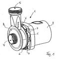
- eine perspektivische Außenansicht einer erfindungsgemäßen Pumpe,
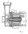
- Fig. 2
- einen Längsschnitt durch die Pumpe aus
Fig. 1 , - Fig. 3
- einen Querschnitt durch den Stator des Pumpenmotors in der Ebene 111 der
Fig. 2 bei Montage der Spulen, - Fig. 4
- den Gegenstand aus
Fig. 3 mit vollständig montierten Spulen und - Fig. 5
- eine perspektivische Darstellung des Gegenstands aus
Fig. 4 ohne Wicklungen auf den Spulen.
- Fig. 1
- an external perspective view of a pump according to the invention,
- Fig. 2
- a longitudinal section through the pump
Fig. 1 . - Fig. 3
- a cross section through the stator of the pump motor in the plane 111 of
Fig. 2 when mounting the coils, - Fig. 4
- the object out
Fig. 3 with fully assembled coils and - Fig. 5
- a perspective view of the subject
Fig. 4 without windings on the coils.
Die in
Das Innere der Pumpe ist in
Der Motor besteht im wesentlichen aus einem feststehenden Statorblechpaket 12, auf dem ebenfalls feststehende Spulen 13 aufgenommen sind, sowie einem Rotor 14, der bei der dargestellten Ausführungsform vorteilhaft als zweipoliger Permanentmagnet ausgebildet ist. Zwischen Rotor 14 und Welle 9 befindet sich mit beiden Teilen fest verbunden ein vorzugsweise massiver und geschlossener Eisenring 15, der den magnetischen Fluß des Motors merklich erhöht.The motor consists essentially of a fixed laminated
An der Motorrückseite ist eine Platine 16 angeordnet, die die gesamte Steuerelektronik beinhaltet. Schließlich verfügt der Motor über einen Erdkontakt 17 am Stator 12 und ein Erdungsbelch 18 an der rückwärtigen Seite des Motorgehäuseteils 3.At the rear of the engine, a circuit board 16 is arranged, which includes the entire control electronics. Finally, the motor has a ground contact 17 on the
Zur Abdichtung des wasserdurchflossenen Gehäuseteils 2 gegenüber dem die elektrischen Komponenten aufnehmenden Gehäuseteil 3 sind der Rotor 14 mit allen beweglichen Teilen und der 12 mit allen stromdurchflossenen Teilen voneinander durch ein den Rotor 14 umgebendes Spaltrohr 19 getrennt. Zum Pumpengehäuseteil 2 hin verbreitert sich das Spaltrohr 19 mit einem großen kragenartigen Flansch 19' zur vollständigen Trennung zwischen Pumpengehäuseteil 2 und Motorgehäuseteil 3. Das Innere des gesamten Motorgehäuseteils 3 ist sämtliche Freiräume ausfüllend vergossen, z.B. mit Kunstharz. Die Vergußmasse 20 umschließt damit auch die gesamte Steuerelektronik 16, so daß diese nicht nur gegen Feuchtigkeit, sondern auch mechanisch gegen Vibrationen geschützt ist. Gleichzeitig stützt die Vergußmasse 20 auch das Spaltrohr 19, und dieses kann kostengünstig aus äußerlich nicht verstärktem Kunststoff gefertigt sein.For sealing the water-carrying housing part 2 relative to the electrical components receiving
Die Steuerelektronik 16 kann eine nicht näher dargestellte Signalauswertungseinheit beinhalten, durch die empfangene Signale zur Drehzahlregelung des Pumpenmotors eingesetzt werden. Die Steuersignale können direkt auf die an den Motor übermittelte Netzspannung aufmoduliert werden. Dadurch entfällt die Notwendigkeit einer aufwendigen Phasen-Anschnittsteuerung zur Drehzahlregelung der Pumpe, wie sie bislang für konventionelle Motoren eingesetzt werden muß. Die Bedienung zur Drehzahlregelung kann insbesondere über einen über eine Fernbedienung ansteuerbaren Zwischenstecker erfolgen, der zwischen dem Netzstrom und dem Stromversorgungskabel für die Pumpe angebracht wird. Dieser Zwischenstrecker beinhaltet ein Empfangsmodul, das die von der Fernbedienung abgegebenen Signale zur Änderung der Motordrehzahl empfängt. Im Zwischensteckerelement werden diese Signale dann auf die Netzspannung aufmoduliert und dadurch an die Steuerelektronik der Pumpe weitergegeben. Das Zwischensteckerelement übernimmt damit nur die Rolle der Signalweitergabe, so daß keine Leistungselektronik erforderlich ist.The control electronics 16 may include a signal evaluation unit, not shown, are used by the received signals for speed control of the pump motor. The control signals can be directly modulated onto the mains voltage transmitted to the motor. This eliminates the need for a complex phase control gate for speed control of the pump, as it must be used for conventional engines so far. The operation for speed control can be done in particular via an activatable via a remote adapter plug, which is mounted between the mains and the power supply cable for the pump. This intermediate spacer includes a Reception module that receives the signals emitted by the remote control to change the engine speed. In the intermediate plug element these signals are then modulated onto the mains voltage and thereby passed on to the control electronics of the pump. The intermediate connector element thus assumes only the role of signal transmission, so that no power electronics is required.
Bei der erfindungsgemäßen Ausführungsform sind der Stator 12 und die zugeordneten Spulen 13 bevorzugt so ausgebildet, daß die Spulen 13 bei der Montage von den Innenseite aus auf Statorpole 22 des Stators 12 aufgeschoben werden können. Dies und der Aufbau des Stators 12 mit den Spulen 13 ist in den
Die Geometrieverhältnisse, die ein Aufschieben der Spulen 13 auf die Statorpole 22 ermöglichen, sind im wesentlichen in
Die erfindungsgemäße Pumpe ist dahingehend optimiert, daß einerseits ihre Abmessungen möglichst klein sein sollten, andererseits jedoch ihr Wirkungsgrad möglichst hoch, und das bei verbesserter Montagefreundlichkeit. Zur Erhöhung des Wirkungsgrades bei vorgegebenen Maximalabmessungen müssen die Geometrieverhältnisse so gewählt werden, daß die Spulen 13 einerseits noch aufgeschoben werden können und andererseits möglichst viele Wicklungen auf den Spulen 13 untergebracht werden können. Dazu ist eine Bogenlänge BL der Statorpole 22 zu definieren. Würde man im Inneren des Stators 12, in dem der Rotor 14 rotiert, einen maximal großen imaginären Kreis unterbringen, der die Statorpolinnenseiten 32 genau berührt, so könnte die Summe der Bogenlängen BL sämtlicher Pole 22 genau der Hälfte des Umfangs des definierten Kreises entsprechen. Zugunsten der unterzubringenden Kupfermenge auf den Spulenwicklungen und zur Vermeidung von Flußstreuungen wird vorzugsweise die Bogenlänge BL jedes Pols 22 jedoch um ca. 11 % bis 12 % gegenüber der soeben definierten ursprünglichen Länge reduziert.The pump according to the invention is optimized so that on the one hand their dimensions should be as small as possible, but on the other hand, their efficiency as high as possible, and with improved ease of installation. To increase the efficiency at predetermined maximum dimensions, the geometry ratios must be selected so that the
Vorteilhaft kann ein Winkel α zwischen zwei sich aus der Statormitte erstreckenden, die Polinnenkanten 42 des Statorpols tangierenden Geraden 50 angegeben werden, der ca. zwischen 0,88 mal 360° geteilt durch die Anzahl n der Statorpole 22 und ca. 0,89 mal 360° geteilt durch die Anzahl n der Statorpole 22 liegt. Bei so optimierten Bedingungen werden die Spulen 13 in die in
Der Stator 12 der dargestellten Ausführungsform hat genau sechs Pole 22. Je nach Anforderung ist es auch möglich, den Motor mit einem Stator 12 mit drei, neun, zwölf, fünfzehn etc. Polen auszustatten. Jedoch werden bei mehr als sechs Polen 22 die Abstände für die Wicklungen der Spulen 13 sehr eng, so daß sich der Montage- und Kostenaufwand erhöht. Ein nur dreipoliger Motor hingegen hat einen verringerten Wirkungsgrad.The
Die erfindungsgemäße Pumpe zeichnet sich durch hohe Montagefreundlichkeit, geringe Herstellungskosten, einen hohen Wirkungsgrad und eine optimierte Bedienfreundlichkeit aus. Sie ist wenig reparaturanfällig und daher nahezu wartungsfrei einsetzbar. Durch ihren hohen Wirkungsgrad und dem verringerten Materialaufwand wird sowohl bei der Herstellung als auch beim Betrieb einer derartigen Pumpe der Energieaufwand minimiert.The pump according to the invention is characterized by high ease of assembly, low production costs, high efficiency and optimized ease of use. It is not prone to repair and therefore almost maintenance-free. Due to their high efficiency and the reduced cost of materials, the energy consumption is minimized both in the production and in the operation of such a pump.
Claims (7)
- Water pump for ponds or the like, having a body (1) which comprises a pump-body portion (2) having an intake opening (4) and an outlet opening (5), in which pump-body portion (2) an impeller (8) having a shaft (9) is rotatably arranged, and which comprises a motor-housing portion (3) in which is held an electronically commutated electric motor, which electronically commutated electric motor has a stator (12) having a plurality of windings (13) arranged on stator poles (22) and has a rotor (14) rotating in the said windings (13), the stator (12) comprising a set of laminations which are each in one piece, and the stator (12) and the rotor (14), which takes the form of a two-pole permanent magnet, being separated from one another by a gap-creating tube (19), characterised in that the stator poles (22), which are each formed on the inside, to be substantially free of any widening, have windings (13) which are slid on from the interior of the stator (12), these components, together with an electronic control system (16) for the motor, are arranged in the motor-housing portion (3), and the stator (12), together with the windings (13) and the electronic control system (16), is encapsulated in the said motor-housing portion (3) to be sealed against water, in such a way that the interior of the entire motor-housing portion (3) is provided with an encapsulating material (20) which fills all the open spaces.
- Water pump according to claim 1, characterised in that the gap-creating tube (19) is composed of plastics material which is not reinforced externally.
- Water pump according to claim 1 or 2, characterised in that a solid iron ring (15) which is at least substantially closed is arranged between the rotor (14) and the shaft (9).
- Water pump according to one of claims 1 to 3, characterised in that the electronic control system (16) comprises a signal analysing unit which analyses signals modulated onto the mains voltage received and uses them to regulate the speed of the pump motor.
- Water pump according to one of claims 1 to 4, characterised in that the following geometrical conditions apply to the stator (12) and the windings (13):


where:a = length of the windings (13),A1 = minimum distance between two opposite inside faces (32) of polesA2 = length of the stator poles (22),b = width of the windings (13),B1 = minimum distance between the inner edges of two poles between which there is precisely one further stator pole (22),B2 = minimum distance in the installed state between the outside edges of two windings between which there is precisely one further winding (13),c = width of the stator poles (22),C = inside width of the windings (13). - Water pump according to one of claims 1 to 5, characterised in that the arcuate length (BL) of the inside face of a stator pole (32) is reduced by approximately 11% to 12% from the circumference of a circle touching the inside faces (32) of the stator poles divided by twice the number of stator poles (22) which there are.
- Water pump according to one of claims 1 to 6, characterised in that the following geometrical condition applies to the stator (12):

where:a = the angle between two straight lines (50) which extend from the centre of the stator and are tangent to the inner edges (42) of a stator pole (22),n = the number of stator poles (22) which there are.
Applications Claiming Priority (1)
| Application Number | Priority Date | Filing Date | Title |
|---|---|---|---|
| DE102006027001A DE102006027001A1 (en) | 2006-06-08 | 2006-06-08 | Water pump for especially ponds, aquariums, fountains and the like |
Publications (3)
| Publication Number | Publication Date |
|---|---|
| EP1865202A2 EP1865202A2 (en) | 2007-12-12 |
| EP1865202A3 EP1865202A3 (en) | 2008-06-04 |
| EP1865202B1 true EP1865202B1 (en) | 2010-08-11 |
Family
ID=38430477
Family Applications (1)
| Application Number | Title | Priority Date | Filing Date |
|---|---|---|---|
| EP07009460A Active EP1865202B1 (en) | 2006-06-08 | 2007-05-11 | Water pump for ponds, aquariums, fountains and similar |
Country Status (7)
| Country | Link |
|---|---|
| US (1) | US20070286752A1 (en) |
| EP (1) | EP1865202B1 (en) |
| CN (1) | CN101086260B (en) |
| AT (1) | ATE477420T1 (en) |
| CA (1) | CA2591191C (en) |
| DE (2) | DE102006027001A1 (en) |
| ES (1) | ES2349154T3 (en) |
Families Citing this family (14)
| Publication number | Priority date | Publication date | Assignee | Title |
|---|---|---|---|---|
| DE102009023231B4 (en) * | 2009-05-29 | 2021-05-06 | Brose Fahrzeugteile SE & Co. Kommanditgesellschaft, Würzburg | Stator for an electric motor |
| US8633623B2 (en) * | 2009-08-18 | 2014-01-21 | Xylem IP Holdings LLC. | Encapsulated submersible pump |
| US9016290B2 (en) | 2011-02-24 | 2015-04-28 | Joseph E. Kovarik | Apparatus for removing a layer of sediment which has settled on the bottom of a pond |
| DE102012209487A1 (en) * | 2012-06-05 | 2013-12-05 | Mahle International Gmbh | Hydrodynamic pump e.g. cooling water pump for internal combustion engine, has electric motor assembly that is provided with an internal rotor and stator that are arranged in or on the pump housing |
| US9130413B2 (en) * | 2012-07-25 | 2015-09-08 | Nidec Motor Corporation | Electric motor having a partially sealed housing |
| DE102012222358A1 (en) | 2012-12-05 | 2014-06-05 | Mahle International Gmbh | Electric fluid pump |
| DE102012222359A1 (en) * | 2012-12-05 | 2014-06-05 | Mahle International Gmbh | Electric fluid pump for use as coolant pumps used in automotive field, has split portion that is connected with hydraulic housing surrounding impeller and sealed with drive housing in drying section through flare or clip connection |
| DE202016103632U1 (en) | 2016-07-07 | 2016-07-29 | Michael Rupp | suction pump |
| US20190128267A1 (en) * | 2016-07-29 | 2019-05-02 | RELIAX MOTORES SA de CV | Integrated electric motor and fluid pump |
| CN108271728B (en) * | 2018-02-06 | 2023-12-05 | 广东博宇集团有限公司 | Aquarium |
| US11168690B2 (en) * | 2019-04-11 | 2021-11-09 | Schaeffler Technologies AG & Co. KG | Integrated motor and pump including axially placed coils |
| CN112354927B (en) * | 2020-03-29 | 2021-09-07 | 苏州市臻湖流体技术有限公司 | Intelligent cleaning linear pump |
| CN112392779A (en) * | 2020-11-27 | 2021-02-23 | 临城清泉水泵制造有限公司 | High-efficiency energy-saving submersible electric pump |
| CN114109847B (en) * | 2021-11-29 | 2024-03-19 | 汉江弘源襄阳碳化硅特种陶瓷有限责任公司 | Composite slurry pump body and manufacturing method thereof |
Family Cites Families (23)
| Publication number | Priority date | Publication date | Assignee | Title |
|---|---|---|---|---|
| US3791773A (en) * | 1972-06-09 | 1974-02-12 | Little Giant Corp | Submersible pump |
| DE3245973A1 (en) * | 1982-12-11 | 1984-06-14 | Allweiler Ag, 7760 Radolfzell | ENGINE PUMP UNIT |
| US4679313A (en) * | 1985-03-08 | 1987-07-14 | Kollmorgen Technologies Corporation | Method of making a servo motor with high energy product magnets |
| US4998865A (en) * | 1988-07-11 | 1991-03-12 | Aisan Kogyo Kabushiki Kaisha | Brushless DC pump with enclosed circuit board |
| US5096390A (en) * | 1990-10-16 | 1992-03-17 | Micropump Corporation | Pump assembly with integral electronically commutated drive system |
| GB2258765B (en) * | 1991-06-27 | 1996-01-10 | Dana Corp | Variable reluctance motor having foil wire wound coils |
| IT1259848B (en) * | 1992-11-27 | 1996-03-28 | Hydor Srl | SYNCHRONOUS ELECTRIC MOTOR, PARTICULARLY FOR IMMERSIBLE PUMPS AND INCORPORATING PUMP SUCH MOTOR |
| DE4301675A1 (en) * | 1993-01-22 | 1994-07-28 | Pierburg Gmbh | Electronic commutator electromotor, e.g. for fan or rotary pump |
| DE4434448C2 (en) * | 1994-09-27 | 1996-10-17 | Richard Halm | Wet rotor canned motor for pumps |
| DE4438130A1 (en) * | 1994-10-27 | 1996-05-02 | Wilo Gmbh | Canned motor |
| US6065946A (en) * | 1997-07-03 | 2000-05-23 | Servo Magnetics, Inc. | Integrated controller pump |
| DE19943862A1 (en) * | 1999-09-13 | 2001-03-15 | Wilo Gmbh | Wet rotor pump with mounting plate |
| JP3752594B2 (en) * | 2000-04-25 | 2006-03-08 | 愛三工業株式会社 | Magnetic coupling pump |
| DE10052797A1 (en) * | 2000-10-25 | 2002-05-08 | Bosch Gmbh Robert | Pump driven by an electric motor and method for producing such a pump |
| JPWO2002055870A1 (en) * | 2001-01-05 | 2004-05-20 | 株式会社日立製作所 | High pressure fuel supply pump |
| JP2002213385A (en) * | 2001-01-19 | 2002-07-31 | Ebara Corp | Canned motor and canned motor pump |
| US6821416B1 (en) * | 2002-09-19 | 2004-11-23 | Aquascape Designs, Inc. | Pond system and related pump |
| US20050063843A1 (en) * | 2003-09-18 | 2005-03-24 | Beckett Corporation | Submersible pump |
| JP4565870B2 (en) * | 2004-03-26 | 2010-10-20 | ミネベア株式会社 | Electric pump |
| US7474024B2 (en) * | 2004-09-15 | 2009-01-06 | Aisan Kogyo Kabushiki Kaisha | Electronic control unit and electric pump |
| DE102004056303A1 (en) * | 2004-11-22 | 2006-06-01 | Minebea Co., Ltd. | Statoranrordnung for an electrical machine, method for producing a stator assembly and DC motor |
| EP1884010B1 (en) * | 2005-05-17 | 2014-04-30 | Carter Fuel Systems, LLC | Bldc motor and pump assembly with encapsulated circuit board |
| DE102007016255B4 (en) * | 2006-04-28 | 2012-11-29 | Bühler Motor GmbH | rotary pump |
-
2006
- 2006-06-08 DE DE102006027001A patent/DE102006027001A1/en not_active Withdrawn
-
2007
- 2007-05-11 EP EP07009460A patent/EP1865202B1/en active Active
- 2007-05-11 DE DE502007004689T patent/DE502007004689D1/en active Active
- 2007-05-11 ES ES07009460T patent/ES2349154T3/en active Active
- 2007-05-11 AT AT07009460T patent/ATE477420T1/en active
- 2007-06-07 CA CA2591191A patent/CA2591191C/en active Active
- 2007-06-08 CN CN2007101102110A patent/CN101086260B/en active Active
- 2007-06-08 US US11/760,045 patent/US20070286752A1/en not_active Abandoned
Also Published As
| Publication number | Publication date |
|---|---|
| CA2591191A1 (en) | 2007-12-08 |
| EP1865202A2 (en) | 2007-12-12 |
| ES2349154T3 (en) | 2010-12-28 |
| CN101086260B (en) | 2012-04-04 |
| CN101086260A (en) | 2007-12-12 |
| CA2591191C (en) | 2015-01-27 |
| DE102006027001A1 (en) | 2007-12-13 |
| ATE477420T1 (en) | 2010-08-15 |
| US20070286752A1 (en) | 2007-12-13 |
| EP1865202A3 (en) | 2008-06-04 |
| DE502007004689D1 (en) | 2010-09-23 |
Similar Documents
| Publication | Publication Date | Title |
|---|---|---|
| EP1865202B1 (en) | Water pump for ponds, aquariums, fountains and similar | |
| DE102006034991B4 (en) | Electric power steering device | |
| EP2302219B1 (en) | Pump unit | |
| DE102010019502B4 (en) | Pump with integrated electronically commutated DC motor | |
| EP2500576B1 (en) | Heat circulation pump | |
| EP1648074B1 (en) | Electrical machine, in particular a DC motor | |
| DE102016202463A1 (en) | Electronic control device, engine control device and electric fluid pump | |
| EP3078099B1 (en) | Stator for an electronically commutated direct current motor | |
| DE112017002406B4 (en) | Drive device and pump device | |
| EP2500575A1 (en) | Heat circulation pump | |
| DE102008000124A1 (en) | Compressor, particularly electric motor propelled compressor, has electric motor which has stator and rotor, where stator is provided with stator connection plate | |
| WO2012123238A1 (en) | Heat circulation pump | |
| EP1648072A2 (en) | Stator assembly for an electric machine | |
| WO2008086879A1 (en) | Pump assembly | |
| WO2007023070A1 (en) | Rotor cover and electric motor | |
| WO2013092917A1 (en) | Electric motor | |
| DE102013020094A1 (en) | Electric motor, in particular radiator fan motor | |
| DE4310226A1 (en) | Electric motor excited by permanent magnets | |
| DE102008064132A1 (en) | Electric machine | |
| WO2013030108A2 (en) | Induction machine having an outside rotor | |
| DE102017222754A1 (en) | Gerotor pump | |
| EP3394960B1 (en) | Centrifugal pump, in particular circulation pump | |
| EP1691468B1 (en) | Pump unit | |
| EP3391509B1 (en) | Electric motor | |
| EP1420503B1 (en) | Motor casing |
Legal Events
| Date | Code | Title | Description |
|---|---|---|---|
| PUAI | Public reference made under article 153(3) epc to a published international application that has entered the european phase |
Free format text: ORIGINAL CODE: 0009012 |
|
| AK | Designated contracting states |
Kind code of ref document: A2 Designated state(s): AT BE BG CH CY CZ DE DK EE ES FI FR GB GR HU IE IS IT LI LT LU LV MC MT NL PL PT RO SE SI SK TR |
|
| AX | Request for extension of the european patent |
Extension state: AL BA HR MK YU |
|
| PUAL | Search report despatched |
Free format text: ORIGINAL CODE: 0009013 |
|
| AK | Designated contracting states |
Kind code of ref document: A3 Designated state(s): AT BE BG CH CY CZ DE DK EE ES FI FR GB GR HU IE IS IT LI LT LU LV MC MT NL PL PT RO SE SI SK TR |
|
| AX | Request for extension of the european patent |
Extension state: AL BA HR MK RS |
|
| 17P | Request for examination filed |
Effective date: 20081125 |
|
| 17Q | First examination report despatched |
Effective date: 20090112 |
|
| AKX | Designation fees paid |
Designated state(s): AT BE BG CH CY CZ DE DK EE ES FI FR GB GR HU IE IS IT LI LT LU LV MC MT NL PL PT RO SE SI SK TR |
|
| GRAP | Despatch of communication of intention to grant a patent |
Free format text: ORIGINAL CODE: EPIDOSNIGR1 |
|
| RTI1 | Title (correction) |
Free format text: WATER PUMP FOR PONDS, AQUARIUMS, FOUNTAINS AND SIMILAR |
|
| GRAS | Grant fee paid |
Free format text: ORIGINAL CODE: EPIDOSNIGR3 |
|
| GRAA | (expected) grant |
Free format text: ORIGINAL CODE: 0009210 |
|
| AK | Designated contracting states |
Kind code of ref document: B1 Designated state(s): AT BE BG CH CY CZ DE DK EE ES FI FR GB GR HU IE IS IT LI LT LU LV MC MT NL PL PT RO SE SI SK TR |
|
| REG | Reference to a national code |
Ref country code: GB Ref legal event code: FG4D Free format text: NOT ENGLISH |
|
| REG | Reference to a national code |
Ref country code: CH Ref legal event code: EP |
|
| REG | Reference to a national code |
Ref country code: IE Ref legal event code: FG4D Free format text: LANGUAGE OF EP DOCUMENT: GERMAN |
|
| REF | Corresponds to: |
Ref document number: 502007004689 Country of ref document: DE Date of ref document: 20100923 Kind code of ref document: P |
|
| REG | Reference to a national code |
Ref country code: NL Ref legal event code: T3 |
|
| REG | Reference to a national code |
Ref country code: ES Ref legal event code: FG2A Effective date: 20101215 |
|
| LTIE | Lt: invalidation of european patent or patent extension |
Effective date: 20100811 |
|
| PG25 | Lapsed in a contracting state [announced via postgrant information from national office to epo] |
Ref country code: FI Free format text: LAPSE BECAUSE OF FAILURE TO SUBMIT A TRANSLATION OF THE DESCRIPTION OR TO PAY THE FEE WITHIN THE PRESCRIBED TIME-LIMIT Effective date: 20100811 Ref country code: LT Free format text: LAPSE BECAUSE OF FAILURE TO SUBMIT A TRANSLATION OF THE DESCRIPTION OR TO PAY THE FEE WITHIN THE PRESCRIBED TIME-LIMIT Effective date: 20100811 |
|
| PG25 | Lapsed in a contracting state [announced via postgrant information from national office to epo] |
Ref country code: SI Free format text: LAPSE BECAUSE OF FAILURE TO SUBMIT A TRANSLATION OF THE DESCRIPTION OR TO PAY THE FEE WITHIN THE PRESCRIBED TIME-LIMIT Effective date: 20100811 Ref country code: PT Free format text: LAPSE BECAUSE OF FAILURE TO SUBMIT A TRANSLATION OF THE DESCRIPTION OR TO PAY THE FEE WITHIN THE PRESCRIBED TIME-LIMIT Effective date: 20101213 Ref country code: PL Free format text: LAPSE BECAUSE OF FAILURE TO SUBMIT A TRANSLATION OF THE DESCRIPTION OR TO PAY THE FEE WITHIN THE PRESCRIBED TIME-LIMIT Effective date: 20100811 Ref country code: BG Free format text: LAPSE BECAUSE OF FAILURE TO SUBMIT A TRANSLATION OF THE DESCRIPTION OR TO PAY THE FEE WITHIN THE PRESCRIBED TIME-LIMIT Effective date: 20101111 Ref country code: CY Free format text: LAPSE BECAUSE OF FAILURE TO SUBMIT A TRANSLATION OF THE DESCRIPTION OR TO PAY THE FEE WITHIN THE PRESCRIBED TIME-LIMIT Effective date: 20100811 Ref country code: IS Free format text: LAPSE BECAUSE OF FAILURE TO SUBMIT A TRANSLATION OF THE DESCRIPTION OR TO PAY THE FEE WITHIN THE PRESCRIBED TIME-LIMIT Effective date: 20101211 |
|
| REG | Reference to a national code |
Ref country code: IE Ref legal event code: FD4D |
|
| PG25 | Lapsed in a contracting state [announced via postgrant information from national office to epo] |
Ref country code: SE Free format text: LAPSE BECAUSE OF FAILURE TO SUBMIT A TRANSLATION OF THE DESCRIPTION OR TO PAY THE FEE WITHIN THE PRESCRIBED TIME-LIMIT Effective date: 20100811 Ref country code: GR Free format text: LAPSE BECAUSE OF FAILURE TO SUBMIT A TRANSLATION OF THE DESCRIPTION OR TO PAY THE FEE WITHIN THE PRESCRIBED TIME-LIMIT Effective date: 20101112 Ref country code: LV Free format text: LAPSE BECAUSE OF FAILURE TO SUBMIT A TRANSLATION OF THE DESCRIPTION OR TO PAY THE FEE WITHIN THE PRESCRIBED TIME-LIMIT Effective date: 20100811 |
|
| PG25 | Lapsed in a contracting state [announced via postgrant information from national office to epo] |
Ref country code: DK Free format text: LAPSE BECAUSE OF FAILURE TO SUBMIT A TRANSLATION OF THE DESCRIPTION OR TO PAY THE FEE WITHIN THE PRESCRIBED TIME-LIMIT Effective date: 20100811 Ref country code: IE Free format text: LAPSE BECAUSE OF FAILURE TO SUBMIT A TRANSLATION OF THE DESCRIPTION OR TO PAY THE FEE WITHIN THE PRESCRIBED TIME-LIMIT Effective date: 20100811 |
|
| PG25 | Lapsed in a contracting state [announced via postgrant information from national office to epo] |
Ref country code: RO Free format text: LAPSE BECAUSE OF FAILURE TO SUBMIT A TRANSLATION OF THE DESCRIPTION OR TO PAY THE FEE WITHIN THE PRESCRIBED TIME-LIMIT Effective date: 20100811 Ref country code: SK Free format text: LAPSE BECAUSE OF FAILURE TO SUBMIT A TRANSLATION OF THE DESCRIPTION OR TO PAY THE FEE WITHIN THE PRESCRIBED TIME-LIMIT Effective date: 20100811 Ref country code: EE Free format text: LAPSE BECAUSE OF FAILURE TO SUBMIT A TRANSLATION OF THE DESCRIPTION OR TO PAY THE FEE WITHIN THE PRESCRIBED TIME-LIMIT Effective date: 20100811 Ref country code: CZ Free format text: LAPSE BECAUSE OF FAILURE TO SUBMIT A TRANSLATION OF THE DESCRIPTION OR TO PAY THE FEE WITHIN THE PRESCRIBED TIME-LIMIT Effective date: 20100811 |
|
| PLBE | No opposition filed within time limit |
Free format text: ORIGINAL CODE: 0009261 |
|
| STAA | Information on the status of an ep patent application or granted ep patent |
Free format text: STATUS: NO OPPOSITION FILED WITHIN TIME LIMIT |
|
| 26N | No opposition filed |
Effective date: 20110512 |
|
| REG | Reference to a national code |
Ref country code: DE Ref legal event code: R097 Ref document number: 502007004689 Country of ref document: DE Effective date: 20110512 |
|
| PG25 | Lapsed in a contracting state [announced via postgrant information from national office to epo] |
Ref country code: MT Free format text: LAPSE BECAUSE OF FAILURE TO SUBMIT A TRANSLATION OF THE DESCRIPTION OR TO PAY THE FEE WITHIN THE PRESCRIBED TIME-LIMIT Effective date: 20100811 Ref country code: MC Free format text: LAPSE BECAUSE OF NON-PAYMENT OF DUE FEES Effective date: 20110531 |
|
| REG | Reference to a national code |
Ref country code: CH Ref legal event code: PL |
|
| PG25 | Lapsed in a contracting state [announced via postgrant information from national office to epo] |
Ref country code: CH Free format text: LAPSE BECAUSE OF NON-PAYMENT OF DUE FEES Effective date: 20110531 Ref country code: LI Free format text: LAPSE BECAUSE OF NON-PAYMENT OF DUE FEES Effective date: 20110531 |
|
| PG25 | Lapsed in a contracting state [announced via postgrant information from national office to epo] |
Ref country code: LU Free format text: LAPSE BECAUSE OF NON-PAYMENT OF DUE FEES Effective date: 20110511 |
|
| REG | Reference to a national code |
Ref country code: AT Ref legal event code: MM01 Ref document number: 477420 Country of ref document: AT Kind code of ref document: T Effective date: 20120511 |
|
| PG25 | Lapsed in a contracting state [announced via postgrant information from national office to epo] |
Ref country code: AT Free format text: LAPSE BECAUSE OF NON-PAYMENT OF DUE FEES Effective date: 20120511 |
|
| PG25 | Lapsed in a contracting state [announced via postgrant information from national office to epo] |
Ref country code: TR Free format text: LAPSE BECAUSE OF FAILURE TO SUBMIT A TRANSLATION OF THE DESCRIPTION OR TO PAY THE FEE WITHIN THE PRESCRIBED TIME-LIMIT Effective date: 20100811 |
|
| PG25 | Lapsed in a contracting state [announced via postgrant information from national office to epo] |
Ref country code: HU Free format text: LAPSE BECAUSE OF FAILURE TO SUBMIT A TRANSLATION OF THE DESCRIPTION OR TO PAY THE FEE WITHIN THE PRESCRIBED TIME-LIMIT Effective date: 20100811 |
|
| REG | Reference to a national code |
Ref country code: FR Ref legal event code: PLFP Year of fee payment: 10 |
|
| REG | Reference to a national code |
Ref country code: FR Ref legal event code: PLFP Year of fee payment: 11 |
|
| REG | Reference to a national code |
Ref country code: FR Ref legal event code: PLFP Year of fee payment: 12 |
|
| PGFP | Annual fee paid to national office [announced via postgrant information from national office to epo] |
Ref country code: NL Payment date: 20230519 Year of fee payment: 17 Ref country code: IT Payment date: 20230531 Year of fee payment: 17 Ref country code: FR Payment date: 20230517 Year of fee payment: 17 Ref country code: ES Payment date: 20230621 Year of fee payment: 17 Ref country code: DE Payment date: 20230519 Year of fee payment: 17 |
|
| PGFP | Annual fee paid to national office [announced via postgrant information from national office to epo] |
Ref country code: BE Payment date: 20230517 Year of fee payment: 17 |
|
| PGFP | Annual fee paid to national office [announced via postgrant information from national office to epo] |
Ref country code: GB Payment date: 20230522 Year of fee payment: 17 |