EP2500552B2 - Dual pump fuel flow system for a gas turbine engine and method of controlling - Google Patents
Dual pump fuel flow system for a gas turbine engine and method of controlling Download PDFInfo
- Publication number
- EP2500552B2 EP2500552B2 EP12160237.9A EP12160237A EP2500552B2 EP 2500552 B2 EP2500552 B2 EP 2500552B2 EP 12160237 A EP12160237 A EP 12160237A EP 2500552 B2 EP2500552 B2 EP 2500552B2
- Authority
- EP
- European Patent Office
- Prior art keywords
- pump
- fuel flow
- fuel
- window
- valve
- Prior art date
- Legal status (The legal status is an assumption and is not a legal conclusion. Google has not performed a legal analysis and makes no representation as to the accuracy of the status listed.)
- Active
Links
Images

Classifications
-
- F—MECHANICAL ENGINEERING; LIGHTING; HEATING; WEAPONS; BLASTING
- F02—COMBUSTION ENGINES; HOT-GAS OR COMBUSTION-PRODUCT ENGINE PLANTS
- F02C—GAS-TURBINE PLANTS; AIR INTAKES FOR JET-PROPULSION PLANTS; CONTROLLING FUEL SUPPLY IN AIR-BREATHING JET-PROPULSION PLANTS
- F02C9/00—Controlling gas-turbine plants; Controlling fuel supply in air- breathing jet-propulsion plants
- F02C9/26—Control of fuel supply
- F02C9/263—Control of fuel supply by means of fuel metering valves
-
- F—MECHANICAL ENGINEERING; LIGHTING; HEATING; WEAPONS; BLASTING
- F02—COMBUSTION ENGINES; HOT-GAS OR COMBUSTION-PRODUCT ENGINE PLANTS
- F02C—GAS-TURBINE PLANTS; AIR INTAKES FOR JET-PROPULSION PLANTS; CONTROLLING FUEL SUPPLY IN AIR-BREATHING JET-PROPULSION PLANTS
- F02C7/00—Features, components parts, details or accessories, not provided for in, or of interest apart form groups F02C1/00 - F02C6/00; Air intakes for jet-propulsion plants
- F02C7/22—Fuel supply systems
- F02C7/236—Fuel delivery systems comprising two or more pumps
Definitions
- cruise bypass window 24a, idling bypass window 24b and check valve 32 enable idling pump 30 to be brought on line when cruise bypass window 24a is fully restricted such that all fuel from cruise pump 20 is flowing either through the actuators or through metering valve 26 and cruise pump 20 is unable to satisfy the fuel flow requirements.
Landscapes
- Engineering & Computer Science (AREA)
- Chemical & Material Sciences (AREA)
- Combustion & Propulsion (AREA)
- Mechanical Engineering (AREA)
- General Engineering & Computer Science (AREA)
- Fuel-Injection Apparatus (AREA)
- Output Control And Ontrol Of Special Type Engine (AREA)
Description
- In a gas turbine engine, oil is distributed to various components, such as bearings, for cooling and lubrication. The oil is heated as it circulates around or through these various components. The oil can be cooled by cooling air or fuel flowing to the combustion chamber. Cooling air is typically taken from the fan, which is expensive and reduces thrust of the engine. Fuel flowing to the combustion chamber can also be used to cool the hot circulating oil. Rejecting heat from the oil into the fuel incurs few of the penalties of air cooling. However, the amount of rejected heat is limited by the maximum temperature tolerable by the fuel.
- The fuel system of a gas turbine engine includes a fuel pump for pressurizing and transporting the fuel through the system to the combustion chamber. The fuel pump is generally a boost stage and single positive displacement main stage which is attached to the gearbox such that the speed of the main fuel pump is proportional to the engine speed. At certain conditions, such as cruise, the engine operates at a relatively high speed while a relatively low fuel flow is required. Further, the main fuel pump stage is typically sized by high power or start conditions, resulting in extra flow capacity at all other engine operation conditions. In this way, the main fuel pump stage results in excess fuel flow. The excess fuel is recycled through a bypass loop to the low pressure side of the main pump. At low fuel requirements, the fuel may be recycled several times before being sent to the combustion chamber. The combination of recycling excess fuel and pump inefficiencies increases the temperature of the fuel. This additional heat limits the amount of heat that can be rejected into the fuel from the circulating oil. Reducing the amount of heat rejected into the fuel by the fuel pump would improve engine performance. Further, a large amount of time spent is in the cruise condition during a flight, and reducing the amount of heat rejected into the fuel by the main pump during the cruise condition may have a larger impact on engine performance than similar reductions during other flight conditions.
-
EP 1557546 discloses a fuel supply system for a gas turbine engine including first and second positive displacement pumps operated simultaneously to supply fuel under pressure from a low pressure source. A combining spill valve controls the output flows from the first and second pumps to combine the outputs of the first and second pumps for supply to a metering valve of the system, and to spill some or all of the output of one or both pumps back to the low pressure supply. A pressure raising valve downstream of the metering valve isolates the fuel system from an associated engine until the fuel pressure upstream of the pressure raising valve exceeds a predetermined pressure and, dependent upon the position of the combining spill valve, reduces the predetermined pressure at which the pressure raising valve opens. DocumentEP1329617 discloses a fuel supply system for gas turbine engines. - Viewed from a first aspect, the present invention provides a fuel flow system for a gas turbine engine as set forth in claim 1.
- Viewed from a second aspect, the present invention provides a method for controlling a fuel flow system for a gas turbine engine as set forth in claim 9.
-
-
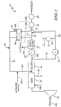
FIG. 1 is a schematic representation of a fuel flow system having a dual window valve. -
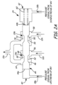
FIG. 2A is a cross-sectional schematic representation of the dual window valve ofFIG. 1 during low fuel flow conditions. -
FIG. 2B is a cross-sectional schematic representation of the dual window valve ofFIG. 1 during high fuel flow conditions. -
FIG. 1 is a schematic representation offuel flow system 10 for a gas turbine engine onboard an aircraft.Fuel flow system 10 receives fuel throughconduit 12a from the air frame (A/F). In one example,fuel flow system 10 receives fuel from a fuel tank onboard the aircraft.Boost pump 14 increases the pressure of the fuel and supplies the fuel to fuel-oil heat exchanger (FOHE) 16 and filter 18. The fuel is then supplied to the system comprisingcruise pump 20,wash filter 22, bypass pressure regulator valve (PRV) 24 (havingcruise bypass window 24a andidle bypass window 24b), metering valve (MV) 26, minimum pressure and shut off valve (MPSOV) 28,idling pump 30, andcheck valve 32.Conduits boost pump 14 to nozzles of a combustion chamber. -
Boost pump 14 receives and pressurizes fuel from the air frame (A/F).Boost pump 14 can be a typical centrifugal pump designed to operate at an essentially constant pressure for a given engine speed. The fuel flows fromboost pump 14 to FOHE 16. - Lubricating and cooling oil for engine components, such as the main engine bearings, circulates through an oil loop represented by
inlet conduit 34a andoutlet conduit 34b. Hot oil from the engine enters FOHE 16 throughinlet conduit 34a. The oil rejects heat into the fuel flowing through FOHE 16. The cooled oil exits FOHE 16 throughconduit 34b and is directed back to the engine components. FOHE 16 transfers heat from the oil to the fuel. The amount of heat transferred to the fuel is limited by the maximum temperature tolerable by the fuel. Decreasing heat rejection by components downstream of FOHE 16 enables more heat to be rejected into the fuel by the oil in FOHE 16. - After FOHE 16, the fuel flows through
filter 18.Filter 18 protects contaminant sensitive components offuel flow system 10. Filter 18 filters contaminants that might enterfuel flow system 10 through the fuel. - After
filter 18, the fuel is divided betweencruise pump 20 andidling pump 30. A portion of the fuel flows throughconduit 12b tocruise pump 20.Cruise pump 20 provides fuel to actuators throughwash filter 22 andconduit 12m.Cruise pump 20 can be a positive displacement pump that is sized, as a minimum, to meet the maximum burn flow requirements at cruise condition plus parasitic internal leakage losses in the fuel system. - The actuators can be high pressure fluid actuators which operate engine components, such as but not limited to, inlet guide vanes, bleed valves, turbine cooling valves and nozzle actuators.
Cruise pump 20 increases the pressure of the fuel sufficiently to satisfy the load requirements of the actuators while also providing fuel to the engine burner nozzles. The minimum pressure and shutoff valve (MPSOV) 28, regulates the discharge pressure ofcruise pump 20 above the inlet pressure ofcruise pump 20 to assure the positive operation of the actuators against their design loads. In one example,cruise pump 20 is operated at about 1724 kilopascals difference (254 psid). High pressure fuel flow is provided to the actuators from the discharge ofcruise pump 20 throughconduit 12m. Low pressure fuel flow from the actuators is returned tobypass loop 36 throughconduit 12n. - Fuel flow from
cruise pump 20 in excess of actuator and engine burn flow needs is directed throughcruise bypass window 24a of bypass pressure regulating valve (PRV) 24 and throughbypass loop 36 comprised ofconduit 12e andconduit 12f. The recycled or bypassed fuel is reintroduced into the fuel flowing to the inlets ofcruise pump 20 andidling pump 30. InFIG. 1 , the bypassed fuel is introduced at a location downstream of the outlet of FOHE 16. -
Cruise bypass window 24a is a variable restriction through which bypass fuel fromcruise pump 20 can flow. The area ofcruise bypass window 24a can be varied to adjust the flow of fuel fromcruise pump 20 throughcruise bypass window 24a.Cruise bypass window 24a is manufactured onPRV 24. -
PRV 24 in conjunction withMV 26 schedules the flow of fuel to the engine burner nozzles.PRV 24 senses pressure upstream and downstream ofMV 26 throughlines PRV 24 regulates the bypass fuel flow by varying cruisebypass window area 24a as necessary to maintain a constant pressure differential between the pressure upstream and downstream ofMV 26. In one example, the metering area ofMV 26 is known as a function of the valve position ofMV 26. SincePRV 24 maintains pressure drop acrossMV 26 to a constant value, the burn flow is scheduled as a function of the valve position ofMV 26. - Fuel from
filter 18 is also fed to idlingpump 30 throughconduit 12g. Similar to cruisepump 20, idlingpump 30 can be a positive displacement pump. Idlingpump 30 operates in parallel withcruise pump 20 and typically has a larger capacity thancruise pump 20. The combined capacity of cruise and idlingpumps pump 30 is approximately two-thirds of the total capacity ofcruise pump 20 and idlingpump 30. - Check
valve 32 and idlingbypass window 24b ofPRV 24 are in fluid communication with idlingpump 30. Checkvalve 32 is designed to default to a closed position so that the fuel flow from idlingpump 30 is directed throughconduit 12h and idlingbypass window 24b to bypass loop 36 (which is comprised ofconduit 12e andconduit 12f). The bypass fuel fromcruise pump 20 and idlingpump 30 mix inconduit 12e. The bypass fuel then flows throughconduit 12f and is directed to a location upstream ofcruise pump 20 and idlingpump 30 and downstream ofboost pump 14. - Idling
bypass window 24b is a variable restriction and operates in a similar fashion ascruise bypass window 24a. Idlingbypass window 24b andcruise bypass window 24a are mechanically linked. AsPRV 24 moves to maintain the pressure drop acrossMV 26,PRV 24 varies the areas of bothcruise bypass window 24a and idlingbypass window 24b.Cruise bypass window 24a and idlingbypass window 24b are both manufactured onPRV 24 and vary together with a predetermined relationship as described further below. Since the capacity ofcruise pump 20 is sized to satisfy engine needs at cruise conditions and no additional flow from idlingpump 30 is required, idlingbypass window 24b is sized to provide minimum restriction to the flow from idlingpump 30 at these conditions and the fuel flow is circulated back to the inlets ofcruise pump 20 and idlingpump 30. - As discussed above,
cruise pump 20 and idlingpump 30 can be positive displacement pumps so that a fixed amount of flow is delivered for each revolution.Cruise pump 20 and idlingpump 30 are connected to an engine gearbox, and the speed ofcruise pump 20 and idlingpump 30 are proportional to the engine speed. Under certain conditions, such as cruise, the engine speed is high while the engine burn fuel flow requirement is relatively low. This results in larger fuel flow being delivered by cruise and idlingpumps bypass loop 36 defined byconduit 12e andconduit 12f. Recycling the fuel is an inefficiency in the pumping system, results in wasted horsepower, and results in additional heat rejected into the fuel. Further the higher the pressure that the pump is operated at, the larger the recirculation loss. - In
fuel flow system 10,cruise pump 20 provides the pressure and flow for both the burn flow path to the nozzles and the flow path to the actuators for some engine operating conditions such as cruise. Further,cruise pump 20 is smaller than idlingpump 30 such that the majority of the displacement is on idlingpump 30.Cruise pump 20 is sized to satisfy the requirements of the maximum cruise condition plus the actuator slew requirements. At thermally critical conditions such as cruise, idlingpump 30 is only recirculating fuel to the outlet ofFOHE 16. The minimum pressure rise of idlingpump 30 can be as low as the pressure drop required for recirculating the fuel. The minimum pressure rise of idlingpump 30 is not limited by the burn flow path (i.e., the requirements of the flow path to the nozzles and actuator requirements). Infuel flow system 10, at thermally critical operating conditions such as cruise,cruise pump 20 is operated at a higher pressure than idlingpump 30. However, the higher pressure is across a small portion of the total displacement ofcruise pump 20 plus idlingpump 30. The larger portion of the displacement is across idlingpump 30 which is operating at a relatively low pressure. For example,cruise pump 20 can be operated at about 1724 kilopascals difference (about 254 psid) and idlingpump 30 can be operated at about 517 kilopascals difference (about 75 psid). Relative to a conventional single pump system where the higher pressure rise (254 psid) would be required to be across the total pump displacement, the design offuel flow system 10 reduces the horsepower required at cruise conditions and the amount of heat rejected by the pumps into the fuel. -
Cruise pump 20 is sized to satisfy the maximum cruise condition plus actuator slew requirements, and idlingpump 30 is sized so thatcruise pump 20 and idlingpump 30 together satisfy the high fuel flow conditions, such as take-off conditions. Idlingpump 30 supplements the fuel flow when flow requirements exceed the capacity ofcruise pump 20.PRV 24,cruise bypass window 24a, idlingbypass window 24b, andcheck valve 32 function to introduce idlingpump 30 output to the main flow path (conduit 12c) when fuel flow beyond the capacity ofcruise pump 20 is required by the engine. More specifically,PRV 24 translates to maintain the pressure drop acrossMV 26 by varyingcruise bypass window 24a andidle bypass window 24b, as described further below with respect toFIG. 2A . -
Cruise bypass window 24a and idlingbypass window 24b are variable restrictions. Closingcruise bypass window 24a increases the restriction and reduces bypass flow fromcruise pump 20, thus making more fuel flow available to satisfy engine bum and actuator requirements. Idlingbypass window 24b operates in a similar manner. At cruise condition when the fuel flow demand is very low, the fuel flow demand is satisfied entirely by the fuel flow fromcruise pump 20. As described above,cruise pump 20 is sized to meet the requirements of the maximum cruise condition and the actuator slew requirements. Further, at the cruise condition, idlingbypass window 24b has a low restriction such that the opening in idlingbypass window 24b is large and approximately all of the fuel from idlingpump 30 passes through idlingbypass window 24b to bypass loop 36 (which is comprised ofconduit 12e andconduit 12f). The low restriction of idlingbypass window 24b minimizes the pressure rise across idlingpump 30 at the cruise condition and reduces the amount of heat rejected into the fuel by idlingpump 30. - When the demand for fuel flow increases,
cruise bypass window 24a is variably restricted. For example, when the pressure drop acrossmetering valve 26 is lower than the regulated value,PRV 24 translates to increase the restriction ofcruise bypass window 24a (i.e., decreases the area available for fuel to flow throughcruise bypass window 24a). Increasing the restriction ofcruise bypass window 24a reduces fuel flow fromcruise pump 20 throughconduit 12e andconduit 12f ofbypass loop 36 and increases the flow of fuel fromcruise pump 20 through the main fuel flow path to the nozzles. The maximum capacity ofcruise pump 20 is reached whencruise bypass window 24a is completely restricted such that all fuel fromcruise pump 20 flows to the nozzles. - As
PRV 24 translates to vary the restriction ofcruise bypass window 24a,PRV 24 also varies the restriction of idlingbypass window 24b. As discussed above,cruise bypass window 24a and idlingbypass window 24b are both manufactured onPRV 24 and vary together with a predetermined relationship. When the capacity ofcruise pump 20 does not meet the fuel flow requirements, additional fuel flow from idlingpump 30 is provided to the engine. Ascruise bypass window 24a is restricted,PRV 24 also increases the restriction of idlingbypass window 24b (i.e., decreases the area available for fluid flow through idlingbypass window 24b). Restricting idlingbypass window 24b increases the pressure of the fuel inconduit 12h andconduit 12i. When the pressure inconduit 12h andconduit 12i is equal to or greater than the pressure inconduit 12c,check valve 32 opens and some of the fuel from idlingpump 30 flows through the main fuel flow path ofconduit 12k to the nozzles.Cruise bypass window 24a, idlingbypass window 24b andcheck valve 32 enable idlingpump 30 to add to the main flow path (conduit pump 30 is needed to satisfy fuel flow requirements. More specifically,cruise bypass window 24a, idlingbypass window 24b andcheck valve 32 enable idlingpump 30 to be brought on line whencruise bypass window 24a is fully restricted such that all fuel fromcruise pump 20 is flowing either through the actuators or throughmetering valve 26 andcruise pump 20 is unable to satisfy the fuel flow requirements. - When
PRV 24 senses a pressure drop greater than the regulated value, the variable restriction ofcruise bypass window 24a and idlingbypass window 24b operates in a converse manner. WhenPRV 24 measures a pressure drop acrossMV 26 greater than the regulated value,PRV 24 translates to reduce the restriction of idlingbypass window 24b (i.e., increases the area available for fluid to flow through idlingbypass window 24b) andcruise bypass window 24a. As idlingbypass window 24b opens, the discharge pressure of idlingpump 30 is reduced. When idlingpump 30 discharge pressure falls below the pressure in the main flow path,check valve 32 closes, and burn and actuation flows are again supplied only bycruise pump 20. -
FIG. 2A is a cross-sectional schematic ofPRV 24 when the fuel flow demand is low, such as at cruise conditions, and all fuel flow demand is met bycruise pump 20.PRV 24 includeshigh pressure side 40,low pressure side 42,spool 44 havingfirst metering edge 48,second metering edge 50,first discharge bucket 52,second discharge bucket 54, firstinlet flow annulus 56, secondinlet flow annulus 58,spring 60, firstoutlet flow annulus 64,first passage 66, secondoutlet flow annulus 70, andsecond passage 72.Spool 44 is slidably located in a housing havinghigh pressure side 40 andlow pressure side 42. High pressure fromline 38a works onhigh pressure end 44a ofspool 44. Low pressure fromline 38b in conjunction withspring 60 works on low pressure end 44b ofspool 44.Spring 60 sets the pressure differential to be maintained acrossMV 26. -
PRV 24 includes first and second inlet annuli 56, 58.First inlet annulus 56 receives fuel flow fromcruise pump 20 throughconduit 12d.First annulus 56 directs the fuel flow tofirst outlet annulus 64 byfirst passage 66. Similarly,second annulus 58 receives fuel flow from idlingpump 30 throughconduit 12h.Second annulus 58 directs the fuel flow tosecond outlet annulus 70 bysecond passage 72. Fuel fromfirst outlet annulus 64 andsecond outlet annulus 70exit PRV 24 and flow throughconduit 12e. -
Spool 44 is a dual window valve havingcruise bypass window 24a and idlingbypass window 24b.Spool 44 is slidably engaged in a housing and includesfirst metering edge 48,first flow passage 52 andfirst exit bucket 46.Cruise bypass window 24a is defined betweenfirst metering edge 48 andfirst inlet annulus 56. As described above, fuel flow fromcruise pump 20 flows into first inlet cavity 62 and throughfirst passage 66 tofirst outlet cavity 64. The position ofspool 44 determines the size ofcruise bypass window 24a. More specifically, the maximum diameter offirst metering edge 48 is greater than the diameter offirst passage 66. Asspool 44 translates to the left,first metering edge 48 moves towardsinlet annulus 56 and the area ofcruise bypass window 24a becomes smaller because there is less area for fuel to flow between thefirst metering edge 48 andfirst annulus 56.Cruise bypass window 24a is closed whenfirst metering edge 48 aligns with the edge offlow annulus 56 and fuel cannot flow throughfirst passage 66. - Idling
bypass window 24b operates in a similar manner. Fuel flow from idlingpump 30 flows intosecond inlet cavity 58 and throughsecond metering window 24b andsecond passage 72 tosecond outlet annulus 70. The position ofspool 44 determines the size of idlingbypass window 24b. More specifically, the maximum diameter ofsecond metering edge 50 is greater than the diameter ofsecond passage 72. Asspool 44 translates to the left,second metering edge 50 moves towardssecond inlet annulus 58 and the area of idlingbypass window 24b becomes smaller because there is less area for fuel to flow between thesecond metering edge 50 andsecond annulus 58. Idlingbypass window 24b is closed whensecond metering edge 50 aligns with the edge offlow annulus 58 and fuel cannot flow throughsecond passage 72. -
Spool 44 translates or slides to simultaneously adjust the size or restriction ofcruise bypass window 24a and idlingbypass window 24b and maintain a constant pressure drop acrossMV 26.FIG. 2A illustratesPRV 24 when the fuel flow demand is low, such as at cruise conditions. In this position, the hydraulic force exerted onhigh pressure end 44a is equal to the sum of the hydraulic force exerted on low pressure end 44b plus the force exerted byspring 60. When the forces are equal, the pressure drop acrossMV 26 is at its desired constant value. During a cruise condition, force equilibrium onspool 44 will occur withcruise bypass window 24a open sufficiently to bypass flow from thecruise pump 20 that is in excess of engine demand back to cruise pump inlet viaconduit 12e. In addition, theidle bypass window 24b is open to a maximum value and directs all flow from the idlingpump 30 fromconduit 12h flows through idlingbypass window 24b toconduit 12e ofbypass loop 36. Withidle bypass window 24b open to a maximum value, restriction in the idle pump bypass path is minimized, which minimizes the pressure rise across the idling pump and therefore minimizes idling pump power. - When engine fuel demand increases,
MV 26 is commanded to a more open position, and the pressure differential betweenline MV 26 decreases) andspool 44 translates to the left.FIG. 2B illustratesPRV 24 during high fuel flow demand conditions, such as take-off. At high fuel flow demand,spool 44 translates to the left, as illustrated, untilfirst metering edge 48 aligns withfirst annulus 56. In this position, fuel fromconduit 12d (i.e., from cruise pump 20) cannot flow throughcruise bypass window 24a and all fuel flow fromcruise pump 20 is directed to the nozzles. Additionally, in this position, idlingbypass window 24b has a smaller cross-sectional area so that fuel flow through idlingbypass window 24b is also restricted. This increase in restriction results in increased pressure rise across idlingpump 30. When the idling pump pressure rise is approximately equal to the cruise pump pressure rise, thecheck valve 32 opens and some idling pump flow is joins with the cruise pump flow. The fuel flow from idlingpump 30 to theMV 26 is increased until MV pressure drop is again established and force balance onPRV spool 40 is restored. - As shown in
FIGS. 2A and2B ,cruise bypass window 24a and idlingbypass window 24b are mechanically linked byspool 44. Translation ofspool 44 affects the areas or restrictions of bothcruise bypass window 24a and idlingbypass window 24b, and because ofspool 44,cruise bypass window 24a and idlingbypass window 24b vary with a known relationship.PRV 24 andspool 44 are designed such thatcruise bypass window 24a is always restricted or closed to a greater extent than idlingbypass window 24b. Because of this design, fuel flow fromcruise pump 20 is first used to satisfy the fuel demands of the engine, and fuel flow from idlingpump 30 is brought on-line to supplement that ofcruise pump 20 during high fuel flow conditions. - As described above,
cruise pump 20 is sized to meet the requirements for maximum cruise condition and the actuator steady-state leakage requirements. Infuel flow system 10,cruise pump 20 provides the pressure and flow for both burn and actuation at the cruise condition, while idlingpump 30 recirculates at a minimum pressure drop. Thus, infuel flow system 10, the higher pressure is across a small portion of the displacement (i.e., cruise pump 20) and the majority of the displacement (i.e., by idling pump 30) is at a relatively low pressure.Fuel flow system 10 results in reduced horsepower of the combination ofcruise pump 20 and idlingpump 30 at cruise conditions relative to a fuel system utilizing a single fuel pump sized for total capacity where the higher pressure would be required to be across the entire displacement. This results in less heat rejection bycruise pump 20 and idlingpump 30 into the fuel and enables greater heat rejection by the oil ofFOHE 16 while maintaining the fuel within the temperature range tolerable by the fuel. - While the invention has been described with reference to an exemplary embodiment, it will be understood by those skilled in the art that various changes may be made and equivalents may be substituted for elements thereof without departing from the scope of the invention, which is defined by the claims. In addition, many modifications may be made to adapt a particular situation or material to the teachings of the invention without departing from the scope thereof. Therefore, it is intended that the invention not be limited to the particular embodiment disclosed, but that the invention will include all embodiments falling within the scope of the appended claims.
Claims (12)
- A fuel flow system (10) for a gas turbine engine, the system comprising:nozzles of a combustion chamber;a first pump (20) connected to an actuator and the nozzles by a main fuel flow path (12c) formed between the first pump, the actuator and the nozzles;a second pump (30) in parallel with the first pump and connected to the main fuel flow path for supplementing fuel flow from the first pump;a check valve (32) connected between the second pump and the main fuel flow path, wherein the check valve is arranged to open when the pressure of the fuel from the second pump is equal to or greater than the pressure of the fuel from the first pump;a fuel-oil heat exchanger (16) disposed upstream from the first pump and the second pump;a boost pump (14) disposed upstream of the fuel-oil heat exchanger;a filter (18) disposed downstream of the fuel-oil heat exchanger and upstream of the first pump and the second pump;a minimum pressure and shut off valve (28) configured to regulate a discharge pressure of the first pump above an inlet pressure of the first pump; a bypass loop (36) connected to the first pump and the second pump for recycling excess fuel from the first pump and excess fuel from the second pump back to inlets of the first and second pumps and downstream from the heat exchanger;a metering valve (26) downstream of the first and second pumps, and upstream from the nozzles; anda dual window valve (24) comprising:a housing having a high pressure side (40), a low pressure side (42), a first inlet annulus (56) connected to the first pump, a first outlet annulus (64) connected to the bypass loop, a first flow passage (66) connected between the first inlet annulus and the first outlet annulus, a second inlet annulus (58) connected to the second pump, a second outlet annulus (70) connected to the bypass loop, and a second flow passage (72) connected between the second inlet and the second outlet;a spool (44) slidably received within the housing and having a high pressure end (44a) proximate the high pressure side of the housing, a low pressure end (44b) proximate the low pressure side of the housing, a first metering edge (48), and a second metering edge (50), wherein the first inlet annulus of the housing and the first metering edge of the spool define a first window (24a), and wherein the second inlet annulus of the housing and the second metering edge of the spool define a second window (24b); anda spring (60) disposed between the low pressure side of the housing and the low pressure end of the spool;wherein the metering valve is in communication with the second pump when the second window is restricted.
- The fuel flow system of claim 1, wherein the first pump has a smaller volume than the second pump.
- The fuel flow system of claim 1 or 2, wherein the first pump operates at a higher pressure than the second pump.
- The fuel flow system of claim 1, 2 or 3, wherein the first pump is sized to satisfy maximum cruise conditions plus actuator slew requirements; and/or
wherein the first pump and the second pump are sized to together satisfy maximum fuel flow conditions. - The fuel flow system of any preceding claim,
wherein the position of the spool is adjusted to maintain a substantially constant pressure drop across the metering valve. - The fuel flow system of any preceding claim, wherein the first window is adjustable upon movement of the spool to regulate the excess fuel from the first pump to the bypass loop and the second window is adjustable upon movement of the spool to regulate the excess fuel from the second pump to the bypass loop.
- The fuel flow system of any preceding claim, wherein the movement of the spool is regulated based on a pressure differential.
- The fuel flow system of any preceding claim, wherein the dual window valve further includes a first port disposed on high pressure side of the housing of the dual window valve for receiving a pressure signal from upstream of the metering valve and a second port disposed on the low pressure side of the housing of the dual window valve for receiving a pressure signal from downstream of the metering valve.
- A method for controlling a fuel flow system (10) for a gas turbine engine, the method comprising the steps of:passing a fuel flow through a boost pump (14);passing the fuel flow through a fuel-oil heat exchanger (16) downstream of the boost pump;passing the fuel flow through a filter (18) downstream of the fuel-oil heat exchanger;dividing the fuel flow downstream from the filter between a first pump (20) and a second pump (30);directing a first portion of the fuel flow from the first pump to an actuator;directing a second portion of fuel flow from the first pump through a main fuel flow path (12c) to a metering valve (26), a minimum pressure and shut off valve (28) and nozzles of a combustion chamber disposed downstream from the metering valve and minimum pressure shut off valve, wherein the metering valve is downstream from the first and second pumps;selectively directing a third portion of the fuel flow from the first pump through a bypass loop (36) to inlets of the first and second pumps downstream from the heat exchanger;selectively directing a first portion of the fuel flow from the second pump through the metering valve and to the nozzles by opening a check valve (32) connected between the second pump and the metering valve when fuel flow from the second pump has a pressure equal to or greater than fuel flow from the first pump; andselectively directing a second portion of the fuel flow from the second pump through the bypass loop to the inlets of the first and second pumps downstream from the heat exchanger;
andwherein the fuel flow system comprises a dual window valve (24) comprising:a housing having a high pressure side (40), a low pressure side (42), a first inlet annulus (56) connected to the first pump, a first outlet annulus (64) connected to the bypass loop, a first flow passage (66) connected between the first inlet annulus and the first outlet annulus, a second inlet annulus (58) connected to the second pump, a second outlet annulus (70) connected to the bypass loop, and a second flow passage (72) connected between the second inlet and the second outlet;a spool (44) slidably received within the housing and having a high pressure end (44a) proximate the high pressure side of the housing, a low pressure end (44b) proximate the low pressure side of the housing, a first metering edge (48), and a second metering edge (50), wherein the first inlet annulus of the housing and the first metering edge of the spool define a first window (24a), and wherein the second inlet annulus of the housing and the second metering edge of the spool define a second window (24b); anda spring (60) disposed between the low pressure side of the housing and the low pressure end of the spool; andwherein the selective directing of the first portion of the fuel flow from the second pump through the metering valve and to the nozzles occurs when the second window is restricted. - The method of claim 9 or 10, and further comprising:reducing an area of the first window (24a) of the dual window valve (24) so that fuel flow through the bypass loop from the first pump is reduced; andreducing an area of the second window (24b) of the dual window valve when the first window is restricted so that fuel flow through the bypass loop from the second pump is reduced.
- The method of claim 10, and further comprising:
reducing the area of the first window when a fuel flow rate through the metering valve is less than a required fuel flow rate. - The method of claim 10 or 11, and further comprising:
increasing the area of the first window when a fuel flow rate through the metering valve is greater than a required fuel flow rate.
Applications Claiming Priority (1)
| Application Number | Priority Date | Filing Date | Title |
|---|---|---|---|
| US13/051,091 US8893466B2 (en) | 2011-03-18 | 2011-03-18 | Dual pump fuel flow system for a gas turbine engine and method of controlling |
Publications (4)
| Publication Number | Publication Date |
|---|---|
| EP2500552A2 EP2500552A2 (en) | 2012-09-19 |
| EP2500552A3 EP2500552A3 (en) | 2013-04-17 |
| EP2500552B1 EP2500552B1 (en) | 2017-06-28 |
| EP2500552B2 true EP2500552B2 (en) | 2023-06-21 |
Family
ID=45894236
Family Applications (1)
| Application Number | Title | Priority Date | Filing Date |
|---|---|---|---|
| EP12160237.9A Active EP2500552B2 (en) | 2011-03-18 | 2012-03-19 | Dual pump fuel flow system for a gas turbine engine and method of controlling |
Country Status (2)
| Country | Link |
|---|---|
| US (1) | US8893466B2 (en) |
| EP (1) | EP2500552B2 (en) |
Families Citing this family (26)
| Publication number | Priority date | Publication date | Assignee | Title |
|---|---|---|---|---|
| US9453463B2 (en) | 2013-01-17 | 2016-09-27 | Honeywell International Inc. | High efficiency, high pressure gas turbine engine fuel supply system |
| US9353688B2 (en) | 2013-01-17 | 2016-05-31 | Honeywell International Inc. | High pressure, multiple metering zone gas turbine engine fuel supply system |
| US8951021B2 (en) * | 2013-01-18 | 2015-02-10 | General Electric Company | Dual pump/dual bypass fuel pumping system |
| US9091212B2 (en) | 2013-03-27 | 2015-07-28 | Hamilton Sundstrand Corporation | Fuel and actuation system for gas turbine engine |
| US9140191B2 (en) | 2013-04-22 | 2015-09-22 | Hamilton Sundstrand Corporation | System for controlling two positive displacement pumps |
| US9212608B2 (en) | 2013-05-24 | 2015-12-15 | Hamilton Sundstrand Corporation | Low friction fuel metering valve |
| JP2015052315A (en) * | 2013-09-09 | 2015-03-19 | 株式会社Ihi | Fuel supply system for gas turbine engine |
| US10066507B1 (en) * | 2015-02-10 | 2018-09-04 | United Technologies Corporation | Turbine engine lubrication system with wash flow filter |
| EP3325787B1 (en) * | 2015-07-21 | 2022-05-11 | Safran Aircraft Engines | Fuel metering device protected against icing |
| US10060379B2 (en) * | 2015-09-04 | 2018-08-28 | Ford Global Technologies, Llc | Method for a hybrid vehicle |
| US10502138B2 (en) * | 2016-04-11 | 2019-12-10 | Hamilton Sundstrand Corporation | Dual pump fuel system with pump sharing connection |
| US10428816B2 (en) * | 2016-10-24 | 2019-10-01 | Hamilton Sundstrand Corporation | Variable speed multi-stage pump |
| US11060461B2 (en) | 2018-12-13 | 2021-07-13 | Hamilton Sundstrand Corporation | Fuel systems having reduced bypass flow |
| US11125169B2 (en) | 2018-12-19 | 2021-09-21 | General Electric Company | Fuel system for heat engine |
| US11203978B2 (en) | 2020-01-20 | 2021-12-21 | Hamilton Sundstrand Corporation | Dual pump unit with boost pump |
| US11649768B2 (en) * | 2021-08-20 | 2023-05-16 | Hamilton Sundstrand Corporation | Pump system for a gas turbine engine |
| US11781483B1 (en) * | 2022-05-03 | 2023-10-10 | Hamilton Sundstrand Corporation | Minimum pressure valve for aircraft fuel system |
| US12146478B2 (en) * | 2022-05-26 | 2024-11-19 | Hamilton Sundstrand Corporation | Dual pump fuel systems |
| US12146461B2 (en) | 2022-05-27 | 2024-11-19 | Hamilton Sundstrand Corporation | Dual valve fuel metering systems |
| US12055099B2 (en) | 2022-07-19 | 2024-08-06 | Hamilton Sundstrand Corporation | Two stage fuel delivery system for an aircraft |
| FR3146322B1 (en) * | 2023-03-01 | 2025-02-07 | Safran Aircraft Engines | Fuel conditioning system for an aircraft turbomachine and method of use |
| US12209538B1 (en) | 2023-09-11 | 2025-01-28 | Hamilton Sundstrand Corporation | Three pump fuel systems with selectable main and augmentor pumps |
| US12366207B2 (en) | 2023-09-11 | 2025-07-22 | Hamilton Sundstrand Corporation | Variable displacement pump (VDP) systems with dry-out centrifugal main pump |
| US12366206B2 (en) | 2023-09-11 | 2025-07-22 | Hamilton Sundstrand Corporation | Variable displacement pump (VDP) systems with dual dry out pumps |
| US12492662B2 (en) * | 2024-02-27 | 2025-12-09 | Hamilton Sundstrand Corporation | Fuel pump with built-in thermal bypass |
| US12352211B1 (en) * | 2024-02-28 | 2025-07-08 | Hamilton Sundstrand Corporation | Dual pump electrified fuel system with parallelism |
Family Cites Families (51)
| Publication number | Priority date | Publication date | Assignee | Title |
|---|---|---|---|---|
| US2506611A (en) | 1948-03-02 | 1950-05-09 | Westinghouse Electric Corp | Fuel control for aviation gas turbine power plants |
| US2761387A (en) | 1950-09-25 | 1956-09-04 | Gen Motors Corp | Fuel system |
| US2835323A (en) | 1953-10-13 | 1958-05-20 | Plessey Co Ltd | Fuel systems for internal combustion engines and gas turbines |
| US2812715A (en) | 1954-06-23 | 1957-11-12 | Westinghouse Electric Corp | Fuel system |
| US2944597A (en) * | 1957-02-20 | 1960-07-12 | Thompson Ramo Wooldridge Inc | Fuel system |
| US3332234A (en) | 1966-03-24 | 1967-07-25 | John P Lavash | Fuel delivery systems |
| US3696612A (en) | 1970-12-30 | 1972-10-10 | Westinghouse Electric Corp | Fuel pump system for gas turbines |
| US3899877A (en) | 1973-07-02 | 1975-08-19 | Gen Motors Corp | Gas turbine engine power shift transmission power train |
| US4151710A (en) | 1977-03-11 | 1979-05-01 | United Technologies Corporation | Lubrication cooling system for aircraft engine accessory |
| US4245964A (en) | 1978-11-08 | 1981-01-20 | United Technologies Corporation | Efficiency fluid pumping system including sequential unloading of a plurality of pumps by a single pressure responsive control valve |
| US4354345A (en) | 1980-04-29 | 1982-10-19 | United Technologies Corporation | Fuel heating system for gas turbine engine |
| GB2111128B (en) | 1981-12-10 | 1984-10-17 | Rolls Royce | Fuel/oil heat exchange system for a gas turbine engine |
| GB2142391B (en) | 1983-07-01 | 1986-03-26 | Honda Motor Co Ltd | Control device for a direct clutch in automatic transmission |
| US4696156A (en) | 1986-06-03 | 1987-09-29 | United Technologies Corporation | Fuel and oil heat management system for a gas turbine engine |
| US4876880A (en) | 1987-03-20 | 1989-10-31 | United Technologies Corporation | Densimeter |
| US4809499A (en) | 1987-03-20 | 1989-03-07 | United Technologies Corporation | Densimeter |
| FR2619417B1 (en) | 1987-08-12 | 1989-12-01 | Snecma | FUEL DISTRIBUTION CIRCUIT WITH INCREASED FUEL COOLING |
| US4910956A (en) | 1988-04-28 | 1990-03-27 | United Technologies Corporation | Gas turbine overtemperature protection |
| DE69010370T2 (en) | 1989-04-06 | 1994-10-20 | Rolls Royce Plc | Fuel control valve for an aircraft engine. |
| US5241814A (en) * | 1989-04-06 | 1993-09-07 | Rolls-Royce Plc | Management of heat generated by aircraft gas turbine installations |
| US5159808A (en) | 1990-07-09 | 1992-11-03 | General Electric Company | Gas turbine engine fuel and hydraulic fluid pumping system |
| US5118258A (en) | 1990-09-04 | 1992-06-02 | United Technologies Corporation | Dual pump fuel delivery system |
| US5156332A (en) | 1991-09-24 | 1992-10-20 | United Technologies Corporation | Pressure regulating flow control apparatus |
| US5339636A (en) | 1992-12-04 | 1994-08-23 | United Technologies Corporation | Fuel splitter valve assembly for gas turbine |
| US5313790A (en) | 1992-12-17 | 1994-05-24 | Alliedsignal Inc. | Endothermic fluid based thermal management system |
| WO1995004224A1 (en) | 1993-08-03 | 1995-02-09 | United Technologies Corporation | Centrifugal fuel pump with starting stage |
| GB2282186B (en) | 1993-09-08 | 1997-09-24 | Rolls Royce Plc | Engine fuel metering system |
| US5442922A (en) | 1993-12-09 | 1995-08-22 | United Technologies Corporation | Fuel staging system |
| US5448882A (en) | 1993-12-14 | 1995-09-12 | United Technologies Corporation | Fuel metering system |
| US5715674A (en) | 1995-12-22 | 1998-02-10 | United Technologies Corporation | Hydromechanical control for a variable delivery, positive displacement fuel pump |
| US5702229A (en) | 1996-10-08 | 1997-12-30 | Walbro Corporation | Regenerative fuel pump |
| US5896737A (en) | 1997-06-16 | 1999-04-27 | United Technologies Corporation | Combined pressure regulating and fuel flow system |
| US6059537A (en) | 1997-11-13 | 2000-05-09 | Sundstrand Corporation | Aircraft fuel pump with centrifugal pump and regenerative pump stages |
| US6022197A (en) | 1997-11-14 | 2000-02-08 | Sundstrand Corporation | Aircraft pump system with internal pressure control, comprising a regenerative pump and a centrifugal pump |
| EP1045964B1 (en) | 1998-01-08 | 2012-08-08 | United Technologies Corporation | Bi-level hydraulic pressurizing system |
| GB9900115D0 (en) | 1999-01-06 | 1999-02-24 | Lucas Ind Plc | Fuel system |
| FR2788561B1 (en) | 1999-01-14 | 2001-02-16 | Snecma | FUEL SYSTEM WITH PROTECTED MAIN FILTER |
| US6250894B1 (en) | 1999-04-07 | 2001-06-26 | United Technologies Corporation | Load sharing valve and system for operating centrifugal pumps in parallel |
| US6189313B1 (en) | 1999-04-16 | 2001-02-20 | Hamilton Sundstrand Corporation | Aircraft engine fuel system mounting assembly |
| US6487847B1 (en) | 2000-11-03 | 2002-12-03 | General Electric Company | Gas turbine engine fuel control system |
| US6655151B2 (en) | 2001-09-07 | 2003-12-02 | Honeywell International, Inc. | Method for controlling fuel flow to a gas turbine engine |
| US6651441B2 (en) | 2002-01-22 | 2003-11-25 | Hamilton Sundstrand | Fluid flow system for a gas turbine engine |
| FR2846711B1 (en) | 2002-10-30 | 2006-09-22 | Hispano Suiza Sa | FUEL ASSAY DEVICE WITH COMPENSATED REGULATING VALVE IN A TURBOMACHINE |
| GB0401207D0 (en) | 2004-01-21 | 2004-02-25 | Goodrich Control Sys Ltd | Fuel supply system |
| EP1819914A2 (en) | 2004-11-19 | 2007-08-22 | Goodrich Pump & Engine Control Systems, Inc. | Two-stage fuel pump for gas turbines |
| GB0508126D0 (en) | 2005-04-22 | 2005-06-01 | Goodrich Control Sys Ltd | Fuel system |
| US7401461B2 (en) | 2005-05-27 | 2008-07-22 | Honeywell International Inc. | Reduced-weight fuel system for gas turbine engine, gas turbine engine having a reduced-weight fuel system, and method of providing fuel to a gas turbine engine using a reduced-weight fuel system |
| US8128378B2 (en) | 2007-07-30 | 2012-03-06 | Honeywell International Inc. | Dual mode compensation for variable displacement pump fluid metering system |
| US8302406B2 (en) | 2008-10-15 | 2012-11-06 | Woodward, Inc. | Fuel delivery and control system including a positive displacement actuation pump with a variable pressure regulator supplementing a fixed displacement main fuel pump |
| FR2950863B1 (en) | 2009-10-06 | 2012-03-02 | Snecma | FUEL SUPPLY CIRCUIT FOR AN AIRCRAFT ENGINE |
| US8596993B2 (en) * | 2010-01-07 | 2013-12-03 | Woodward, Inc. | Dual-pump supply system with bypass-controlled flow regulator |
-
2011
- 2011-03-18 US US13/051,091 patent/US8893466B2/en active Active
-
2012
- 2012-03-19 EP EP12160237.9A patent/EP2500552B2/en active Active
Also Published As
| Publication number | Publication date |
|---|---|
| US8893466B2 (en) | 2014-11-25 |
| EP2500552A3 (en) | 2013-04-17 |
| EP2500552A2 (en) | 2012-09-19 |
| US20120234015A1 (en) | 2012-09-20 |
| EP2500552B1 (en) | 2017-06-28 |
Similar Documents
| Publication | Publication Date | Title |
|---|---|---|
| EP2500552B2 (en) | Dual pump fuel flow system for a gas turbine engine and method of controlling | |
| EP2500551B1 (en) | Fuel flow control system and method for controlling two positive displacement pumps | |
| US8166765B2 (en) | Fuel delivery and control system including a variable displacement actuation pump supplementing a fixed displacement main pump | |
| US8302406B2 (en) | Fuel delivery and control system including a positive displacement actuation pump with a variable pressure regulator supplementing a fixed displacement main fuel pump | |
| EP3232036B1 (en) | Dual pump fuel system with pump sharing connection | |
| US6651441B2 (en) | Fluid flow system for a gas turbine engine | |
| EP2784270B1 (en) | Fuel and actuation system for gas turbine engine and a corresponding method. | |
| EP3257744B1 (en) | Propeller blade angle control system | |
| EP2521848B1 (en) | Dual-supply fluid distribution system and method of supplying fluid | |
| EP2891781B1 (en) | Engine fuel control system | |
| US8881870B2 (en) | Recirculation valve in an aircraft engine | |
| EP2891768B1 (en) | Engine fuel control system | |
| EP3712410B1 (en) | Mechanical demand fuel pumping system | |
| US10793256B2 (en) | Propeller blade angle control system |
Legal Events
| Date | Code | Title | Description |
|---|---|---|---|
| PUAI | Public reference made under article 153(3) epc to a published international application that has entered the european phase |
Free format text: ORIGINAL CODE: 0009012 |
|
| AK | Designated contracting states |
Kind code of ref document: A2 Designated state(s): AL AT BE BG CH CY CZ DE DK EE ES FI FR GB GR HR HU IE IS IT LI LT LU LV MC MK MT NL NO PL PT RO RS SE SI SK SM TR |
|
| AX | Request for extension of the european patent |
Extension state: BA ME |
|
| PUAL | Search report despatched |
Free format text: ORIGINAL CODE: 0009013 |
|
| AK | Designated contracting states |
Kind code of ref document: A3 Designated state(s): AL AT BE BG CH CY CZ DE DK EE ES FI FR GB GR HR HU IE IS IT LI LT LU LV MC MK MT NL NO PL PT RO RS SE SI SK SM TR |
|
| AX | Request for extension of the european patent |
Extension state: BA ME |
|
| RIC1 | Information provided on ipc code assigned before grant |
Ipc: F02C 9/26 20060101AFI20130314BHEP Ipc: F02C 7/236 20060101ALI20130314BHEP |
|
| 17P | Request for examination filed |
Effective date: 20131017 |
|
| RBV | Designated contracting states (corrected) |
Designated state(s): AL AT BE BG CH CY CZ DE DK EE ES FI FR GB GR HR HU IE IS IT LI LT LU LV MC MK MT NL NO PL PT RO RS SE SI SK SM TR |
|
| GRAP | Despatch of communication of intention to grant a patent |
Free format text: ORIGINAL CODE: EPIDOSNIGR1 |
|
| STAA | Information on the status of an ep patent application or granted ep patent |
Free format text: STATUS: GRANT OF PATENT IS INTENDED |
|
| INTG | Intention to grant announced |
Effective date: 20170315 |
|
| GRAS | Grant fee paid |
Free format text: ORIGINAL CODE: EPIDOSNIGR3 |
|
| GRAA | (expected) grant |
Free format text: ORIGINAL CODE: 0009210 |
|
| STAA | Information on the status of an ep patent application or granted ep patent |
Free format text: STATUS: THE PATENT HAS BEEN GRANTED |
|
| AK | Designated contracting states |
Kind code of ref document: B1 Designated state(s): AL AT BE BG CH CY CZ DE DK EE ES FI FR GB GR HR HU IE IS IT LI LT LU LV MC MK MT NL NO PL PT RO RS SE SI SK SM TR |
|
| REG | Reference to a national code |
Ref country code: GB Ref legal event code: FG4D |
|
| REG | Reference to a national code |
Ref country code: CH Ref legal event code: EP |
|
| REG | Reference to a national code |
Ref country code: AT Ref legal event code: REF Ref document number: 905067 Country of ref document: AT Kind code of ref document: T Effective date: 20170715 |
|
| REG | Reference to a national code |
Ref country code: IE Ref legal event code: FG4D |
|
| REG | Reference to a national code |
Ref country code: DE Ref legal event code: R096 Ref document number: 602012033887 Country of ref document: DE |
|
| PG25 | Lapsed in a contracting state [announced via postgrant information from national office to epo] |
Ref country code: NO Free format text: LAPSE BECAUSE OF FAILURE TO SUBMIT A TRANSLATION OF THE DESCRIPTION OR TO PAY THE FEE WITHIN THE PRESCRIBED TIME-LIMIT Effective date: 20170928 Ref country code: GR Free format text: LAPSE BECAUSE OF FAILURE TO SUBMIT A TRANSLATION OF THE DESCRIPTION OR TO PAY THE FEE WITHIN THE PRESCRIBED TIME-LIMIT Effective date: 20170929 Ref country code: HR Free format text: LAPSE BECAUSE OF FAILURE TO SUBMIT A TRANSLATION OF THE DESCRIPTION OR TO PAY THE FEE WITHIN THE PRESCRIBED TIME-LIMIT Effective date: 20170628 Ref country code: FI Free format text: LAPSE BECAUSE OF FAILURE TO SUBMIT A TRANSLATION OF THE DESCRIPTION OR TO PAY THE FEE WITHIN THE PRESCRIBED TIME-LIMIT Effective date: 20170628 Ref country code: LT Free format text: LAPSE BECAUSE OF FAILURE TO SUBMIT A TRANSLATION OF THE DESCRIPTION OR TO PAY THE FEE WITHIN THE PRESCRIBED TIME-LIMIT Effective date: 20170628 |
|
| REG | Reference to a national code |
Ref country code: NL Ref legal event code: MP Effective date: 20170628 |
|
| REG | Reference to a national code |
Ref country code: LT Ref legal event code: MG4D |
|
| REG | Reference to a national code |
Ref country code: AT Ref legal event code: MK05 Ref document number: 905067 Country of ref document: AT Kind code of ref document: T Effective date: 20170628 |
|
| PG25 | Lapsed in a contracting state [announced via postgrant information from national office to epo] |
Ref country code: LV Free format text: LAPSE BECAUSE OF FAILURE TO SUBMIT A TRANSLATION OF THE DESCRIPTION OR TO PAY THE FEE WITHIN THE PRESCRIBED TIME-LIMIT Effective date: 20170628 Ref country code: SE Free format text: LAPSE BECAUSE OF FAILURE TO SUBMIT A TRANSLATION OF THE DESCRIPTION OR TO PAY THE FEE WITHIN THE PRESCRIBED TIME-LIMIT Effective date: 20170628 Ref country code: BG Free format text: LAPSE BECAUSE OF FAILURE TO SUBMIT A TRANSLATION OF THE DESCRIPTION OR TO PAY THE FEE WITHIN THE PRESCRIBED TIME-LIMIT Effective date: 20170928 Ref country code: NL Free format text: LAPSE BECAUSE OF FAILURE TO SUBMIT A TRANSLATION OF THE DESCRIPTION OR TO PAY THE FEE WITHIN THE PRESCRIBED TIME-LIMIT Effective date: 20170628 Ref country code: RS Free format text: LAPSE BECAUSE OF FAILURE TO SUBMIT A TRANSLATION OF THE DESCRIPTION OR TO PAY THE FEE WITHIN THE PRESCRIBED TIME-LIMIT Effective date: 20170628 |
|
| PG25 | Lapsed in a contracting state [announced via postgrant information from national office to epo] |
Ref country code: AT Free format text: LAPSE BECAUSE OF FAILURE TO SUBMIT A TRANSLATION OF THE DESCRIPTION OR TO PAY THE FEE WITHIN THE PRESCRIBED TIME-LIMIT Effective date: 20170628 Ref country code: RO Free format text: LAPSE BECAUSE OF FAILURE TO SUBMIT A TRANSLATION OF THE DESCRIPTION OR TO PAY THE FEE WITHIN THE PRESCRIBED TIME-LIMIT Effective date: 20170628 Ref country code: CZ Free format text: LAPSE BECAUSE OF FAILURE TO SUBMIT A TRANSLATION OF THE DESCRIPTION OR TO PAY THE FEE WITHIN THE PRESCRIBED TIME-LIMIT Effective date: 20170628 Ref country code: SK Free format text: LAPSE BECAUSE OF FAILURE TO SUBMIT A TRANSLATION OF THE DESCRIPTION OR TO PAY THE FEE WITHIN THE PRESCRIBED TIME-LIMIT Effective date: 20170628 Ref country code: EE Free format text: LAPSE BECAUSE OF FAILURE TO SUBMIT A TRANSLATION OF THE DESCRIPTION OR TO PAY THE FEE WITHIN THE PRESCRIBED TIME-LIMIT Effective date: 20170628 |
|
| REG | Reference to a national code |
Ref country code: FR Ref legal event code: PLFP Year of fee payment: 7 |
|
| PG25 | Lapsed in a contracting state [announced via postgrant information from national office to epo] |
Ref country code: IT Free format text: LAPSE BECAUSE OF FAILURE TO SUBMIT A TRANSLATION OF THE DESCRIPTION OR TO PAY THE FEE WITHIN THE PRESCRIBED TIME-LIMIT Effective date: 20170628 Ref country code: IS Free format text: LAPSE BECAUSE OF FAILURE TO SUBMIT A TRANSLATION OF THE DESCRIPTION OR TO PAY THE FEE WITHIN THE PRESCRIBED TIME-LIMIT Effective date: 20171028 Ref country code: PL Free format text: LAPSE BECAUSE OF FAILURE TO SUBMIT A TRANSLATION OF THE DESCRIPTION OR TO PAY THE FEE WITHIN THE PRESCRIBED TIME-LIMIT Effective date: 20170628 Ref country code: ES Free format text: LAPSE BECAUSE OF FAILURE TO SUBMIT A TRANSLATION OF THE DESCRIPTION OR TO PAY THE FEE WITHIN THE PRESCRIBED TIME-LIMIT Effective date: 20170628 Ref country code: SM Free format text: LAPSE BECAUSE OF FAILURE TO SUBMIT A TRANSLATION OF THE DESCRIPTION OR TO PAY THE FEE WITHIN THE PRESCRIBED TIME-LIMIT Effective date: 20170628 |
|
| REG | Reference to a national code |
Ref country code: DE Ref legal event code: R026 Ref document number: 602012033887 Country of ref document: DE |
|
| PLBI | Opposition filed |
Free format text: ORIGINAL CODE: 0009260 |
|
| PLAX | Notice of opposition and request to file observation + time limit sent |
Free format text: ORIGINAL CODE: EPIDOSNOBS2 |
|
| PG25 | Lapsed in a contracting state [announced via postgrant information from national office to epo] |
Ref country code: DK Free format text: LAPSE BECAUSE OF FAILURE TO SUBMIT A TRANSLATION OF THE DESCRIPTION OR TO PAY THE FEE WITHIN THE PRESCRIBED TIME-LIMIT Effective date: 20170628 |
|
| 26 | Opposition filed |
Opponent name: SAFRAN AIRCRAFT ENGINES Effective date: 20180328 |
|
| PLBB | Reply of patent proprietor to notice(s) of opposition received |
Free format text: ORIGINAL CODE: EPIDOSNOBS3 |
|
| PG25 | Lapsed in a contracting state [announced via postgrant information from national office to epo] |
Ref country code: SI Free format text: LAPSE BECAUSE OF FAILURE TO SUBMIT A TRANSLATION OF THE DESCRIPTION OR TO PAY THE FEE WITHIN THE PRESCRIBED TIME-LIMIT Effective date: 20170628 |
|
| REG | Reference to a national code |
Ref country code: DE Ref legal event code: R119 Ref document number: 602012033887 Country of ref document: DE |
|
| REG | Reference to a national code |
Ref country code: CH Ref legal event code: PL |
|
| PG25 | Lapsed in a contracting state [announced via postgrant information from national office to epo] |
Ref country code: MC Free format text: LAPSE BECAUSE OF FAILURE TO SUBMIT A TRANSLATION OF THE DESCRIPTION OR TO PAY THE FEE WITHIN THE PRESCRIBED TIME-LIMIT Effective date: 20170628 |
|
| REG | Reference to a national code |
Ref country code: BE Ref legal event code: MM Effective date: 20180331 |
|
| REG | Reference to a national code |
Ref country code: IE Ref legal event code: MM4A |
|
| PG25 | Lapsed in a contracting state [announced via postgrant information from national office to epo] |
Ref country code: LU Free format text: LAPSE BECAUSE OF NON-PAYMENT OF DUE FEES Effective date: 20180319 |
|
| PG25 | Lapsed in a contracting state [announced via postgrant information from national office to epo] |
Ref country code: DE Free format text: LAPSE BECAUSE OF NON-PAYMENT OF DUE FEES Effective date: 20181002 Ref country code: IE Free format text: LAPSE BECAUSE OF NON-PAYMENT OF DUE FEES Effective date: 20180319 |
|
| PG25 | Lapsed in a contracting state [announced via postgrant information from national office to epo] |
Ref country code: CH Free format text: LAPSE BECAUSE OF NON-PAYMENT OF DUE FEES Effective date: 20180331 Ref country code: LI Free format text: LAPSE BECAUSE OF NON-PAYMENT OF DUE FEES Effective date: 20180331 Ref country code: BE Free format text: LAPSE BECAUSE OF NON-PAYMENT OF DUE FEES Effective date: 20180331 |
|
| APAH | Appeal reference modified |
Free format text: ORIGINAL CODE: EPIDOSCREFNO |
|
| APBM | Appeal reference recorded |
Free format text: ORIGINAL CODE: EPIDOSNREFNO |
|
| APBP | Date of receipt of notice of appeal recorded |
Free format text: ORIGINAL CODE: EPIDOSNNOA2O |
|
| PG25 | Lapsed in a contracting state [announced via postgrant information from national office to epo] |
Ref country code: MT Free format text: LAPSE BECAUSE OF NON-PAYMENT OF DUE FEES Effective date: 20180319 |
|
| APBQ | Date of receipt of statement of grounds of appeal recorded |
Free format text: ORIGINAL CODE: EPIDOSNNOA3O |
|
| PG25 | Lapsed in a contracting state [announced via postgrant information from national office to epo] |
Ref country code: TR Free format text: LAPSE BECAUSE OF FAILURE TO SUBMIT A TRANSLATION OF THE DESCRIPTION OR TO PAY THE FEE WITHIN THE PRESCRIBED TIME-LIMIT Effective date: 20170628 |
|
| PG25 | Lapsed in a contracting state [announced via postgrant information from national office to epo] |
Ref country code: HU Free format text: LAPSE BECAUSE OF FAILURE TO SUBMIT A TRANSLATION OF THE DESCRIPTION OR TO PAY THE FEE WITHIN THE PRESCRIBED TIME-LIMIT; INVALID AB INITIO Effective date: 20120319 Ref country code: PT Free format text: LAPSE BECAUSE OF FAILURE TO SUBMIT A TRANSLATION OF THE DESCRIPTION OR TO PAY THE FEE WITHIN THE PRESCRIBED TIME-LIMIT Effective date: 20170628 |
|
| PG25 | Lapsed in a contracting state [announced via postgrant information from national office to epo] |
Ref country code: MK Free format text: LAPSE BECAUSE OF NON-PAYMENT OF DUE FEES Effective date: 20170628 Ref country code: CY Free format text: LAPSE BECAUSE OF FAILURE TO SUBMIT A TRANSLATION OF THE DESCRIPTION OR TO PAY THE FEE WITHIN THE PRESCRIBED TIME-LIMIT Effective date: 20170628 |
|
| PG25 | Lapsed in a contracting state [announced via postgrant information from national office to epo] |
Ref country code: AL Free format text: LAPSE BECAUSE OF FAILURE TO SUBMIT A TRANSLATION OF THE DESCRIPTION OR TO PAY THE FEE WITHIN THE PRESCRIBED TIME-LIMIT Effective date: 20170628 |
|
| APBU | Appeal procedure closed |
Free format text: ORIGINAL CODE: EPIDOSNNOA9O |
|
| PUAH | Patent maintained in amended form |
Free format text: ORIGINAL CODE: 0009272 |
|
| STAA | Information on the status of an ep patent application or granted ep patent |
Free format text: STATUS: PATENT MAINTAINED AS AMENDED |
|
| 27A | Patent maintained in amended form |
Effective date: 20230621 |
|
| AK | Designated contracting states |
Kind code of ref document: B2 Designated state(s): AL AT BE BG CH CY CZ DE DK EE ES FI FR GB GR HR HU IE IS IT LI LT LU LV MC MK MT NL NO PL PT RO RS SE SI SK SM TR |
|
| REG | Reference to a national code |
Ref country code: DE Ref legal event code: R102 Ref document number: 602012033887 Country of ref document: DE |
|
| P01 | Opt-out of the competence of the unified patent court (upc) registered |
Effective date: 20230522 |
|
| PGFP | Annual fee paid to national office [announced via postgrant information from national office to epo] |
Ref country code: FR Payment date: 20250218 Year of fee payment: 14 |
|
| PGFP | Annual fee paid to national office [announced via postgrant information from national office to epo] |
Ref country code: GB Payment date: 20250221 Year of fee payment: 14 |