EP2500552B2 - Kraftstoff-Durchflusssystem mit zwei Pumpen für einen Gasturbinenmotor und Regelungsverfahren - Google Patents
Kraftstoff-Durchflusssystem mit zwei Pumpen für einen Gasturbinenmotor und Regelungsverfahren Download PDFInfo
- Publication number
- EP2500552B2 EP2500552B2 EP12160237.9A EP12160237A EP2500552B2 EP 2500552 B2 EP2500552 B2 EP 2500552B2 EP 12160237 A EP12160237 A EP 12160237A EP 2500552 B2 EP2500552 B2 EP 2500552B2
- Authority
- EP
- European Patent Office
- Prior art keywords
- pump
- fuel flow
- fuel
- window
- valve
- Prior art date
- Legal status (The legal status is an assumption and is not a legal conclusion. Google has not performed a legal analysis and makes no representation as to the accuracy of the status listed.)
- Active
Links
Images

Classifications
-
- F—MECHANICAL ENGINEERING; LIGHTING; HEATING; WEAPONS; BLASTING
- F02—COMBUSTION ENGINES; HOT-GAS OR COMBUSTION-PRODUCT ENGINE PLANTS
- F02C—GAS-TURBINE PLANTS; AIR INTAKES FOR JET-PROPULSION PLANTS; CONTROLLING FUEL SUPPLY IN AIR-BREATHING JET-PROPULSION PLANTS
- F02C9/00—Controlling gas-turbine plants; Controlling fuel supply in air- breathing jet-propulsion plants
- F02C9/26—Control of fuel supply
- F02C9/263—Control of fuel supply by means of fuel metering valves
-
- F—MECHANICAL ENGINEERING; LIGHTING; HEATING; WEAPONS; BLASTING
- F02—COMBUSTION ENGINES; HOT-GAS OR COMBUSTION-PRODUCT ENGINE PLANTS
- F02C—GAS-TURBINE PLANTS; AIR INTAKES FOR JET-PROPULSION PLANTS; CONTROLLING FUEL SUPPLY IN AIR-BREATHING JET-PROPULSION PLANTS
- F02C7/00—Features, components parts, details or accessories, not provided for in, or of interest apart form groups F02C1/00 - F02C6/00; Air intakes for jet-propulsion plants
- F02C7/22—Fuel supply systems
- F02C7/236—Fuel delivery systems comprising two or more pumps
Definitions
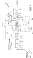
- cruise bypass window 24a, idling bypass window 24b and check valve 32 enable idling pump 30 to be brought on line when cruise bypass window 24a is fully restricted such that all fuel from cruise pump 20 is flowing either through the actuators or through metering valve 26 and cruise pump 20 is unable to satisfy the fuel flow requirements.
Landscapes
- Engineering & Computer Science (AREA)
- Chemical & Material Sciences (AREA)
- Combustion & Propulsion (AREA)
- Mechanical Engineering (AREA)
- General Engineering & Computer Science (AREA)
- Fuel-Injection Apparatus (AREA)
- Output Control And Ontrol Of Special Type Engine (AREA)
Claims (12)
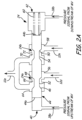
- Kraftstoff-Durchflusssystem (10) für einen Gasturbinenmotor, wobei das System Folgendes umfasst:Düsen einer Brennkammer;eine erste Pumpe (20), die mit einem Stellglied und den Düsen durch einen Hauptkraftstoffdurchflussweg (12c) verbunden ist, der zwischen der ersten Pumpe, dem Stellglied und den Düsen gebildet ist;eine zweite Pumpe (30) parallel zu der ersten Pumpe und verbunden mit dem Hauptkraftstoffdurchflussweg, um den Kraftstoffdurchfluss von der ersten Pumpe zu ergänzen;ein Rückschlagventil (32), das zwischen der zweiten Pumpe und dem Hauptkraftstoffdurchflussweg verbunden ist, wobei das Rückschlagventil dazu ausgelegt ist, sich zu öffnen, wenn der Druck des Kraftstoffs von der zweiten Pumpe gleich dem oder größer als der Druck des Kraftstoffs von der ersten Pumpe ist;einen Kraftstoff-Öl-Wärmetauscher (16), der stromaufwärts von der ersten Pumpe und der zweiten Pumpe angeordnet ist;eine Verstärkerpumpe (14), die stromaufwärts des Kraftstoff-Öl-Wärmetauschers angeordnet ist;einen Filter (18), der stromabwärts des Kraftstoff-Öl-Wärmetauschers und stromaufwärts der ersten Pumpe und der zweiten Pumpe angeordnet ist;ein Mindestdruck- und Absperrventil (28), das dazu konfiguriert ist, einen Förderdruck der ersten Pumpe über einen Einlassdruck der ersten Pumpe zu regulieren;eine Umgehungsschleife (36), die mit der ersten Pumpe und der zweiten Pumpe verbunden ist, um überschüssigen Kraftstoff von der ersten Pumpe und überschüssigen Kraftstoff von der zweiten Pumpe zurück zu Einlässen der ersten und zweiten Pumpe und stromabwärts vom Wärmetauscher zu leiten;ein Dosierventil (26) stromabwärts von der ersten und zweiten Pumpe und stromaufwärts von den Düsen; undein Doppelfensterventil (24), umfassend:ein Gehäuse mit einer Hochdruckseite (40), einer Niederdruckseite (42), einem ersten Einlassring (56), der mit der ersten Pumpe verbunden ist, einem ersten Auslassring (64), der mit der Umgehungsschleife verbunden ist, einem ersten Durchflusskanal (66), der zwischen dem ersten Einlassring und dem ersten Auslassring verbunden ist, einem zweiten Einlassring (58), der mit der zweiten Pumpe verbunden ist, einem zweiten Auslassring (70), der mit der Umgehungsschleife verbunden ist, und einem zweiten Durchflusskanal (72), der zwischen dem zweiten Einlass und dem zweiten Auslass verbunden ist;ein Schieber (44), der verschiebbar in dem Gehäuse aufgenommen ist und ein Hochdruckende (44a) nahe der Hochdruckseite des Gehäuses, ein Niederdruckende (44b) nahe der Niederdruckseite des Gehäuses, eine erste Dosierkante (48) und eine zweite Dosierkante (50) aufweist, wobei der erste Einlassring des Gehäuses und die erste Dosierkante der Spule ein erstes Fenster (24a) definieren und wobei der zweite Einlassring des Gehäuses und die zweite Dosierkante der Spule ein zweites Fenster (24b) definieren; undeine Feder (60), die zwischen der Niederdruckseite des Gehäuses und dem Niederdruckende der Spule angeordnet ist;wobei das Dosierventil in Verbindung mit der zweiten Pumpe steht, wenn das zweite Fenster eingeschränkt ist.
- Kraftstoff-Durchflusssystem nach Anspruch 1, wobei die erste Pumpe ein kleineres Volumen als die zweite Pumpe aufweist.
- Kraftstoff-Durchflusssystem nach Anspruch 1 oder 2, wobei die erste Pumpe bei einem höheren Druck als die zweite Pumpe arbeitet.
- Kraftstoff-Durchflusssystem nach Anspruch 1, 2 oder 3, wobei die erste Pumpe dazu bemessen ist, maximale Reiseflugbedingungen plus Stellgliedschwenkanforderungen zu erfüllen; und/oder
wobei die erste Pumpe und die zweite Pumpe dazu bemessen sind, gemeinsam maximale Kraftstoffdurchflussbedingungen zu erfüllen. - Kraftstoff-Durchflusssystem nach einem der vorhergehenden Ansprüche,
wobei die Position der Spule eingestellt wird, um einen im Wesentlichen konstanten Druckabfall an dem Dosierventil beizubehalten. - Kraftstoff-Durchflusssystem nach einem der vorhergehenden Ansprüche, wobei das erste Fenster bei Bewegung des Schiebers einstellbar ist, um den überschüssigen Kraftstoff von der ersten Pumpe an die Umgehungsschleife zu regulieren, und das zweite Fenster bei Bewegung des Schiebers einstellbar ist, um den überschüssigen Kraftstoff von der zweiten Pumpe an die Umgehungsschleife zu regulieren.
- Kraftstoff-Durchflusssystem nach einem der vorhergehenden Ansprüche, wobei die Bewegung des Schiebers auf Grundlage einer Druckdifferenz reguliert wird.
- Kraftstoff-Durchflusssystem nach einem der vorhergehenden Ansprüche, wobei das Doppelfensterventil ferner eine erste Öffnung, die auf der Hochdruckseite des Gehäuses des Doppelfensterventils angeordnet ist, um ein Drucksignal von stromaufwärts des Dosierventils zu empfangen, und eine zweite Öffnung beinhaltet, die auf der Niederdruckseite des Gehäuses des Doppelfensterventils angeordnet ist, um ein Drucksignal von stromabwärts des Dosierventils zu empfangen.
- Verfahren zum Regeln eines Kraftstoff-Durchflusssystems (10) für einen Gasturbinenmotor, wobei das Verfahren folgende Schritte umfasst:Leiten eines Kraftstoffdurchflusses durch eine Verstärkerpumpe (14) ;Leiten des Kraftstoffdurchflusses durch einen Kraftstoff-Öl-Wärmetauscher (16) stromabwärts der Verstärkerpumpe;Leiten des Kraftstoffdurchflusses durch einen Filter (18) stromabwärts des Kraftstoff-Öl-Wärmetauschers;Aufteilen des Kraftstoffflusses stromabwärts von dem Filter zwischen einer ersten Pumpe (20) und einer zweiten Pumpe (30);Lenken eines ersten Teils des Kraftstoffdurchflusses von der ersten Pumpe zu einem Stellglied;Lenken eines zweiten Teils des Kraftstoffdurchflusses von der ersten Pumpe durch einen Hauptkraftstoffdurchflussweg (12c) zu einem Dosierventil (26), einem Mindestdruck- und Absperrventil (28) und Düsen einer Brennkammer, die stromabwärts von dem Dosierventil und dem Mindestdruck- und Absperrventil angeordnet sind, wobei sich das Dosierventil stromabwärts der ersten und zweiten Pumpe befindet;selektives Lenken eines dritten Teils des Kraftstoffdurchflusses von der ersten Pumpe durch eine Umgehungsschleife (36) zu Einlässen der ersten und zweiten Pumpe stromabwärts von dem Wärmetauscher;selektives Lenken eines ersten Teils des Kraftstoffdurchflusses von der zweiten Pumpe durch das Dosierventil und zu den Düsen durch Öffnen eines Rückschlagventils (32), das zwischen der zweiten Pumpe und dem Dosierventil verbunden ist, wenn Kraftstoffdurchfluss von der zweiten Pumpe einen Druck gleich oder größer als Kraftstoffdurchfluss von der ersten Pumpe aufweist; undselektives Lenken eines zweiten Teils des Kraftstoffdurchflusses von der zweiten Pumpe durch die Umgehungsschleife zu den Einlässen der ersten und zweiten Pumpe stromabwärts von dem Wärmetauscher;
undwobei das Kraftstoff-Durchflusssystem ein Doppelfensterventil (24) umfasst, umfassend:ein Gehäuse mit einer Hochdruckseite (40), einer Niederdruckseite (42), einem ersten Einlassring (56), der mit der ersten Pumpe verbunden ist, einem ersten Auslassring (64), der mit der Umgehungsschleife verbunden ist, einem ersten Durchflusskanal (66), der zwischen dem ersten Einlassring und dem ersten Auslassring verbunden ist, einem zweiten Einlassring (58), der mit der zweiten Pumpe verbunden ist, einem zweiten Auslassring (70), der mit der Umgehungsschleife verbunden ist, und einem zweiten Durchflusskanal (72), der zwischen dem zweiten Einlass und dem zweiten Auslass verbunden ist;eine Spule (44), die verschiebbar in dem Gehäuse aufgenommen ist und ein Hochdruckende (44a) nahe der Hochdruckseite des Gehäuses, ein Niederdruckende (44b) nahe der Niederdruckseite des Gehäuses, eine erste Dosierkante (48) und eine zweite Dosierkante (50) aufweist, wobei der erste Einlassring des Gehäuses und die erste Dosierkante der Spule ein erstes Fenster (24a) definieren und wobei der zweite Einlassring des Gehäuses und die zweite Dosierkante der Spule ein zweites Fenster (24b) definieren; und eine Feder (60), die zwischen der Niederdruckseite des Gehäuses und dem Niederdruckende der Spule angeordnet ist; undwobei das selektive Lenken des ersten Teils des Kraftstoffdurchflusses von der zweiten Pumpe durch das Dosierventil und zu den Düsen stattfindet, wenn das zweite Fenster eingeschränkt ist. - Verfahren nach Anspruch 9 oder 10 und ferner umfassend:Reduzieren eines Bereichs des ersten Fensters (24a) des Doppelfensterventils (24), sodass der Kraftstoffdurchfluss durch die Umgehungsschleife von der ersten Pumpe reduziert wird; undReduzieren eines Bereichs des zweiten Fensters (24b) des Doppelfensterventils, wenn das erste Fenster eingeschränkt ist, sodass der Kraftstoffdurchfluss durch die Umgehungsschleife von der zweiten Pumpe reduziert wird.
- Verfahren nach Anspruch 10 und ferner umfassend:
Reduzieren eines Bereichs des ersten Fensters, wenn eine Kraftstoffdurchflussrate durch das Dosierventil kleiner als eine erforderliche Kraftstoffdurchflussrate ist. - Verfahren nach Anspruch 10 oder 11 und ferner umfassend:
Vergrößern des Bereichs des ersten Fensters, wenn eine Kraftstoffdurchflussrate durch das Dosierventil größer als eine erforderliche Kraftstoffdurchflussrate ist.
Applications Claiming Priority (1)
| Application Number | Priority Date | Filing Date | Title |
|---|---|---|---|
| US13/051,091 US8893466B2 (en) | 2011-03-18 | 2011-03-18 | Dual pump fuel flow system for a gas turbine engine and method of controlling |
Publications (4)
| Publication Number | Publication Date |
|---|---|
| EP2500552A2 EP2500552A2 (de) | 2012-09-19 |
| EP2500552A3 EP2500552A3 (de) | 2013-04-17 |
| EP2500552B1 EP2500552B1 (de) | 2017-06-28 |
| EP2500552B2 true EP2500552B2 (de) | 2023-06-21 |
Family
ID=45894236
Family Applications (1)
| Application Number | Title | Priority Date | Filing Date |
|---|---|---|---|
| EP12160237.9A Active EP2500552B2 (de) | 2011-03-18 | 2012-03-19 | Kraftstoff-Durchflusssystem mit zwei Pumpen für einen Gasturbinenmotor und Regelungsverfahren |
Country Status (2)
| Country | Link |
|---|---|
| US (1) | US8893466B2 (de) |
| EP (1) | EP2500552B2 (de) |
Families Citing this family (26)
| Publication number | Priority date | Publication date | Assignee | Title |
|---|---|---|---|---|
| US9453463B2 (en) | 2013-01-17 | 2016-09-27 | Honeywell International Inc. | High efficiency, high pressure gas turbine engine fuel supply system |
| US9353688B2 (en) | 2013-01-17 | 2016-05-31 | Honeywell International Inc. | High pressure, multiple metering zone gas turbine engine fuel supply system |
| US8951021B2 (en) * | 2013-01-18 | 2015-02-10 | General Electric Company | Dual pump/dual bypass fuel pumping system |
| US9091212B2 (en) | 2013-03-27 | 2015-07-28 | Hamilton Sundstrand Corporation | Fuel and actuation system for gas turbine engine |
| US9140191B2 (en) | 2013-04-22 | 2015-09-22 | Hamilton Sundstrand Corporation | System for controlling two positive displacement pumps |
| US9212608B2 (en) | 2013-05-24 | 2015-12-15 | Hamilton Sundstrand Corporation | Low friction fuel metering valve |
| JP2015052315A (ja) * | 2013-09-09 | 2015-03-19 | 株式会社Ihi | ガスタービンエンジン用の燃料供給システム |
| US10066507B1 (en) * | 2015-02-10 | 2018-09-04 | United Technologies Corporation | Turbine engine lubrication system with wash flow filter |
| EP3325787B1 (de) * | 2015-07-21 | 2022-05-11 | Safran Aircraft Engines | Gegen vereisung geschützte kraftstoffmessvorrichtung |
| US10060379B2 (en) * | 2015-09-04 | 2018-08-28 | Ford Global Technologies, Llc | Method for a hybrid vehicle |
| US10502138B2 (en) * | 2016-04-11 | 2019-12-10 | Hamilton Sundstrand Corporation | Dual pump fuel system with pump sharing connection |
| US10428816B2 (en) * | 2016-10-24 | 2019-10-01 | Hamilton Sundstrand Corporation | Variable speed multi-stage pump |
| US11060461B2 (en) | 2018-12-13 | 2021-07-13 | Hamilton Sundstrand Corporation | Fuel systems having reduced bypass flow |
| US11125169B2 (en) | 2018-12-19 | 2021-09-21 | General Electric Company | Fuel system for heat engine |
| US11203978B2 (en) | 2020-01-20 | 2021-12-21 | Hamilton Sundstrand Corporation | Dual pump unit with boost pump |
| US11649768B2 (en) * | 2021-08-20 | 2023-05-16 | Hamilton Sundstrand Corporation | Pump system for a gas turbine engine |
| US11781483B1 (en) * | 2022-05-03 | 2023-10-10 | Hamilton Sundstrand Corporation | Minimum pressure valve for aircraft fuel system |
| US12146478B2 (en) * | 2022-05-26 | 2024-11-19 | Hamilton Sundstrand Corporation | Dual pump fuel systems |
| US12146461B2 (en) | 2022-05-27 | 2024-11-19 | Hamilton Sundstrand Corporation | Dual valve fuel metering systems |
| US12055099B2 (en) | 2022-07-19 | 2024-08-06 | Hamilton Sundstrand Corporation | Two stage fuel delivery system for an aircraft |
| FR3146322B1 (fr) * | 2023-03-01 | 2025-02-07 | Safran Aircraft Engines | Système de conditionnement de carburant pour une turbomachine d’aéronef et procédé d’utilisation |
| US12209538B1 (en) | 2023-09-11 | 2025-01-28 | Hamilton Sundstrand Corporation | Three pump fuel systems with selectable main and augmentor pumps |
| US12366207B2 (en) | 2023-09-11 | 2025-07-22 | Hamilton Sundstrand Corporation | Variable displacement pump (VDP) systems with dry-out centrifugal main pump |
| US12366206B2 (en) | 2023-09-11 | 2025-07-22 | Hamilton Sundstrand Corporation | Variable displacement pump (VDP) systems with dual dry out pumps |
| US12492662B2 (en) * | 2024-02-27 | 2025-12-09 | Hamilton Sundstrand Corporation | Fuel pump with built-in thermal bypass |
| US12352211B1 (en) * | 2024-02-28 | 2025-07-08 | Hamilton Sundstrand Corporation | Dual pump electrified fuel system with parallelism |
Family Cites Families (51)
| Publication number | Priority date | Publication date | Assignee | Title |
|---|---|---|---|---|
| US2506611A (en) | 1948-03-02 | 1950-05-09 | Westinghouse Electric Corp | Fuel control for aviation gas turbine power plants |
| US2761387A (en) | 1950-09-25 | 1956-09-04 | Gen Motors Corp | Fuel system |
| US2835323A (en) | 1953-10-13 | 1958-05-20 | Plessey Co Ltd | Fuel systems for internal combustion engines and gas turbines |
| US2812715A (en) | 1954-06-23 | 1957-11-12 | Westinghouse Electric Corp | Fuel system |
| US2944597A (en) * | 1957-02-20 | 1960-07-12 | Thompson Ramo Wooldridge Inc | Fuel system |
| US3332234A (en) | 1966-03-24 | 1967-07-25 | John P Lavash | Fuel delivery systems |
| US3696612A (en) | 1970-12-30 | 1972-10-10 | Westinghouse Electric Corp | Fuel pump system for gas turbines |
| US3899877A (en) | 1973-07-02 | 1975-08-19 | Gen Motors Corp | Gas turbine engine power shift transmission power train |
| US4151710A (en) | 1977-03-11 | 1979-05-01 | United Technologies Corporation | Lubrication cooling system for aircraft engine accessory |
| US4245964A (en) | 1978-11-08 | 1981-01-20 | United Technologies Corporation | Efficiency fluid pumping system including sequential unloading of a plurality of pumps by a single pressure responsive control valve |
| US4354345A (en) | 1980-04-29 | 1982-10-19 | United Technologies Corporation | Fuel heating system for gas turbine engine |
| GB2111128B (en) | 1981-12-10 | 1984-10-17 | Rolls Royce | Fuel/oil heat exchange system for a gas turbine engine |
| GB2142391B (en) | 1983-07-01 | 1986-03-26 | Honda Motor Co Ltd | Control device for a direct clutch in automatic transmission |
| US4696156A (en) | 1986-06-03 | 1987-09-29 | United Technologies Corporation | Fuel and oil heat management system for a gas turbine engine |
| US4876880A (en) | 1987-03-20 | 1989-10-31 | United Technologies Corporation | Densimeter |
| US4809499A (en) | 1987-03-20 | 1989-03-07 | United Technologies Corporation | Densimeter |
| FR2619417B1 (fr) | 1987-08-12 | 1989-12-01 | Snecma | Circuit de distribution de carburant a refroidissement accru du carburant |
| US4910956A (en) | 1988-04-28 | 1990-03-27 | United Technologies Corporation | Gas turbine overtemperature protection |
| DE69010370T2 (de) | 1989-04-06 | 1994-10-20 | Rolls Royce Plc | Kraftstoffregelventil für ein Flugtriebwerk. |
| US5241814A (en) * | 1989-04-06 | 1993-09-07 | Rolls-Royce Plc | Management of heat generated by aircraft gas turbine installations |
| US5159808A (en) | 1990-07-09 | 1992-11-03 | General Electric Company | Gas turbine engine fuel and hydraulic fluid pumping system |
| US5118258A (en) | 1990-09-04 | 1992-06-02 | United Technologies Corporation | Dual pump fuel delivery system |
| US5156332A (en) | 1991-09-24 | 1992-10-20 | United Technologies Corporation | Pressure regulating flow control apparatus |
| US5339636A (en) | 1992-12-04 | 1994-08-23 | United Technologies Corporation | Fuel splitter valve assembly for gas turbine |
| US5313790A (en) | 1992-12-17 | 1994-05-24 | Alliedsignal Inc. | Endothermic fluid based thermal management system |
| WO1995004224A1 (en) | 1993-08-03 | 1995-02-09 | United Technologies Corporation | Centrifugal fuel pump with starting stage |
| GB2282186B (en) | 1993-09-08 | 1997-09-24 | Rolls Royce Plc | Engine fuel metering system |
| US5442922A (en) | 1993-12-09 | 1995-08-22 | United Technologies Corporation | Fuel staging system |
| US5448882A (en) | 1993-12-14 | 1995-09-12 | United Technologies Corporation | Fuel metering system |
| US5715674A (en) | 1995-12-22 | 1998-02-10 | United Technologies Corporation | Hydromechanical control for a variable delivery, positive displacement fuel pump |
| US5702229A (en) | 1996-10-08 | 1997-12-30 | Walbro Corporation | Regenerative fuel pump |
| US5896737A (en) | 1997-06-16 | 1999-04-27 | United Technologies Corporation | Combined pressure regulating and fuel flow system |
| US6059537A (en) | 1997-11-13 | 2000-05-09 | Sundstrand Corporation | Aircraft fuel pump with centrifugal pump and regenerative pump stages |
| US6022197A (en) | 1997-11-14 | 2000-02-08 | Sundstrand Corporation | Aircraft pump system with internal pressure control, comprising a regenerative pump and a centrifugal pump |
| EP1045964B1 (de) | 1998-01-08 | 2012-08-08 | United Technologies Corporation | Zweistufiges hydraulikdrucksystem |
| GB9900115D0 (en) | 1999-01-06 | 1999-02-24 | Lucas Ind Plc | Fuel system |
| FR2788561B1 (fr) | 1999-01-14 | 2001-02-16 | Snecma | Circuit de carburant a filtre principal protege |
| US6250894B1 (en) | 1999-04-07 | 2001-06-26 | United Technologies Corporation | Load sharing valve and system for operating centrifugal pumps in parallel |
| US6189313B1 (en) | 1999-04-16 | 2001-02-20 | Hamilton Sundstrand Corporation | Aircraft engine fuel system mounting assembly |
| US6487847B1 (en) | 2000-11-03 | 2002-12-03 | General Electric Company | Gas turbine engine fuel control system |
| US6655151B2 (en) | 2001-09-07 | 2003-12-02 | Honeywell International, Inc. | Method for controlling fuel flow to a gas turbine engine |
| US6651441B2 (en) | 2002-01-22 | 2003-11-25 | Hamilton Sundstrand | Fluid flow system for a gas turbine engine |
| FR2846711B1 (fr) | 2002-10-30 | 2006-09-22 | Hispano Suiza Sa | Dispositif de dosage de carburant a soupape de regulation compensee, dans une turbomachine |
| GB0401207D0 (en) | 2004-01-21 | 2004-02-25 | Goodrich Control Sys Ltd | Fuel supply system |
| EP1819914A2 (de) | 2004-11-19 | 2007-08-22 | Goodrich Pump & Engine Control Systems, Inc. | Zweistufen-treibstoffpumpe für gasturbinen |
| GB0508126D0 (en) | 2005-04-22 | 2005-06-01 | Goodrich Control Sys Ltd | Fuel system |
| US7401461B2 (en) | 2005-05-27 | 2008-07-22 | Honeywell International Inc. | Reduced-weight fuel system for gas turbine engine, gas turbine engine having a reduced-weight fuel system, and method of providing fuel to a gas turbine engine using a reduced-weight fuel system |
| US8128378B2 (en) | 2007-07-30 | 2012-03-06 | Honeywell International Inc. | Dual mode compensation for variable displacement pump fluid metering system |
| US8302406B2 (en) | 2008-10-15 | 2012-11-06 | Woodward, Inc. | Fuel delivery and control system including a positive displacement actuation pump with a variable pressure regulator supplementing a fixed displacement main fuel pump |
| FR2950863B1 (fr) | 2009-10-06 | 2012-03-02 | Snecma | Circuit d'alimentation en carburant d'un moteur d'aeronef |
| US8596993B2 (en) * | 2010-01-07 | 2013-12-03 | Woodward, Inc. | Dual-pump supply system with bypass-controlled flow regulator |
-
2011
- 2011-03-18 US US13/051,091 patent/US8893466B2/en active Active
-
2012
- 2012-03-19 EP EP12160237.9A patent/EP2500552B2/de active Active
Also Published As
| Publication number | Publication date |
|---|---|
| US8893466B2 (en) | 2014-11-25 |
| EP2500552A3 (de) | 2013-04-17 |
| EP2500552A2 (de) | 2012-09-19 |
| US20120234015A1 (en) | 2012-09-20 |
| EP2500552B1 (de) | 2017-06-28 |
Similar Documents
| Publication | Publication Date | Title |
|---|---|---|
| EP2500552B2 (de) | Kraftstoff-Durchflusssystem mit zwei Pumpen für einen Gasturbinenmotor und Regelungsverfahren | |
| EP2500551B1 (de) | Kraftstoff-Durchfluss-Regelungssystem und Verfahren zum Regeln von zwei Verdrängerpumpen | |
| US8166765B2 (en) | Fuel delivery and control system including a variable displacement actuation pump supplementing a fixed displacement main pump | |
| US8302406B2 (en) | Fuel delivery and control system including a positive displacement actuation pump with a variable pressure regulator supplementing a fixed displacement main fuel pump | |
| EP3232036B1 (de) | Doppelpumpen-kraftstoffsystem mit pumpenteilungsverbindung | |
| US6651441B2 (en) | Fluid flow system for a gas turbine engine | |
| EP2784270B1 (de) | Brennstoff- und Betätigungssystem für Gasturbinenmotor sowie dazugehöriges Verfahren | |
| EP3257744B1 (de) | System zur steuerung eines propellerschaufelwinkels | |
| EP2521848B1 (de) | Doppel-Fluidzuführsystem und Fluidzuleitungsverfahren | |
| EP2891781B1 (de) | Motorkraftstoffsteuersystem | |
| US8881870B2 (en) | Recirculation valve in an aircraft engine | |
| EP2891768B1 (de) | Motorkraftstoffregelsystem | |
| EP3712410B1 (de) | Mechanisches bedarfsgesteuertes kraftstoffpumpsystem | |
| US10793256B2 (en) | Propeller blade angle control system |
Legal Events
| Date | Code | Title | Description |
|---|---|---|---|
| PUAI | Public reference made under article 153(3) epc to a published international application that has entered the european phase |
Free format text: ORIGINAL CODE: 0009012 |
|
| AK | Designated contracting states |
Kind code of ref document: A2 Designated state(s): AL AT BE BG CH CY CZ DE DK EE ES FI FR GB GR HR HU IE IS IT LI LT LU LV MC MK MT NL NO PL PT RO RS SE SI SK SM TR |
|
| AX | Request for extension of the european patent |
Extension state: BA ME |
|
| PUAL | Search report despatched |
Free format text: ORIGINAL CODE: 0009013 |
|
| AK | Designated contracting states |
Kind code of ref document: A3 Designated state(s): AL AT BE BG CH CY CZ DE DK EE ES FI FR GB GR HR HU IE IS IT LI LT LU LV MC MK MT NL NO PL PT RO RS SE SI SK SM TR |
|
| AX | Request for extension of the european patent |
Extension state: BA ME |
|
| RIC1 | Information provided on ipc code assigned before grant |
Ipc: F02C 9/26 20060101AFI20130314BHEP Ipc: F02C 7/236 20060101ALI20130314BHEP |
|
| 17P | Request for examination filed |
Effective date: 20131017 |
|
| RBV | Designated contracting states (corrected) |
Designated state(s): AL AT BE BG CH CY CZ DE DK EE ES FI FR GB GR HR HU IE IS IT LI LT LU LV MC MK MT NL NO PL PT RO RS SE SI SK SM TR |
|
| GRAP | Despatch of communication of intention to grant a patent |
Free format text: ORIGINAL CODE: EPIDOSNIGR1 |
|
| STAA | Information on the status of an ep patent application or granted ep patent |
Free format text: STATUS: GRANT OF PATENT IS INTENDED |
|
| INTG | Intention to grant announced |
Effective date: 20170315 |
|
| GRAS | Grant fee paid |
Free format text: ORIGINAL CODE: EPIDOSNIGR3 |
|
| GRAA | (expected) grant |
Free format text: ORIGINAL CODE: 0009210 |
|
| STAA | Information on the status of an ep patent application or granted ep patent |
Free format text: STATUS: THE PATENT HAS BEEN GRANTED |
|
| AK | Designated contracting states |
Kind code of ref document: B1 Designated state(s): AL AT BE BG CH CY CZ DE DK EE ES FI FR GB GR HR HU IE IS IT LI LT LU LV MC MK MT NL NO PL PT RO RS SE SI SK SM TR |
|
| REG | Reference to a national code |
Ref country code: GB Ref legal event code: FG4D |
|
| REG | Reference to a national code |
Ref country code: CH Ref legal event code: EP |
|
| REG | Reference to a national code |
Ref country code: AT Ref legal event code: REF Ref document number: 905067 Country of ref document: AT Kind code of ref document: T Effective date: 20170715 |
|
| REG | Reference to a national code |
Ref country code: IE Ref legal event code: FG4D |
|
| REG | Reference to a national code |
Ref country code: DE Ref legal event code: R096 Ref document number: 602012033887 Country of ref document: DE |
|
| PG25 | Lapsed in a contracting state [announced via postgrant information from national office to epo] |
Ref country code: NO Free format text: LAPSE BECAUSE OF FAILURE TO SUBMIT A TRANSLATION OF THE DESCRIPTION OR TO PAY THE FEE WITHIN THE PRESCRIBED TIME-LIMIT Effective date: 20170928 Ref country code: GR Free format text: LAPSE BECAUSE OF FAILURE TO SUBMIT A TRANSLATION OF THE DESCRIPTION OR TO PAY THE FEE WITHIN THE PRESCRIBED TIME-LIMIT Effective date: 20170929 Ref country code: HR Free format text: LAPSE BECAUSE OF FAILURE TO SUBMIT A TRANSLATION OF THE DESCRIPTION OR TO PAY THE FEE WITHIN THE PRESCRIBED TIME-LIMIT Effective date: 20170628 Ref country code: FI Free format text: LAPSE BECAUSE OF FAILURE TO SUBMIT A TRANSLATION OF THE DESCRIPTION OR TO PAY THE FEE WITHIN THE PRESCRIBED TIME-LIMIT Effective date: 20170628 Ref country code: LT Free format text: LAPSE BECAUSE OF FAILURE TO SUBMIT A TRANSLATION OF THE DESCRIPTION OR TO PAY THE FEE WITHIN THE PRESCRIBED TIME-LIMIT Effective date: 20170628 |
|
| REG | Reference to a national code |
Ref country code: NL Ref legal event code: MP Effective date: 20170628 |
|
| REG | Reference to a national code |
Ref country code: LT Ref legal event code: MG4D |
|
| REG | Reference to a national code |
Ref country code: AT Ref legal event code: MK05 Ref document number: 905067 Country of ref document: AT Kind code of ref document: T Effective date: 20170628 |
|
| PG25 | Lapsed in a contracting state [announced via postgrant information from national office to epo] |
Ref country code: LV Free format text: LAPSE BECAUSE OF FAILURE TO SUBMIT A TRANSLATION OF THE DESCRIPTION OR TO PAY THE FEE WITHIN THE PRESCRIBED TIME-LIMIT Effective date: 20170628 Ref country code: SE Free format text: LAPSE BECAUSE OF FAILURE TO SUBMIT A TRANSLATION OF THE DESCRIPTION OR TO PAY THE FEE WITHIN THE PRESCRIBED TIME-LIMIT Effective date: 20170628 Ref country code: BG Free format text: LAPSE BECAUSE OF FAILURE TO SUBMIT A TRANSLATION OF THE DESCRIPTION OR TO PAY THE FEE WITHIN THE PRESCRIBED TIME-LIMIT Effective date: 20170928 Ref country code: NL Free format text: LAPSE BECAUSE OF FAILURE TO SUBMIT A TRANSLATION OF THE DESCRIPTION OR TO PAY THE FEE WITHIN THE PRESCRIBED TIME-LIMIT Effective date: 20170628 Ref country code: RS Free format text: LAPSE BECAUSE OF FAILURE TO SUBMIT A TRANSLATION OF THE DESCRIPTION OR TO PAY THE FEE WITHIN THE PRESCRIBED TIME-LIMIT Effective date: 20170628 |
|
| PG25 | Lapsed in a contracting state [announced via postgrant information from national office to epo] |
Ref country code: AT Free format text: LAPSE BECAUSE OF FAILURE TO SUBMIT A TRANSLATION OF THE DESCRIPTION OR TO PAY THE FEE WITHIN THE PRESCRIBED TIME-LIMIT Effective date: 20170628 Ref country code: RO Free format text: LAPSE BECAUSE OF FAILURE TO SUBMIT A TRANSLATION OF THE DESCRIPTION OR TO PAY THE FEE WITHIN THE PRESCRIBED TIME-LIMIT Effective date: 20170628 Ref country code: CZ Free format text: LAPSE BECAUSE OF FAILURE TO SUBMIT A TRANSLATION OF THE DESCRIPTION OR TO PAY THE FEE WITHIN THE PRESCRIBED TIME-LIMIT Effective date: 20170628 Ref country code: SK Free format text: LAPSE BECAUSE OF FAILURE TO SUBMIT A TRANSLATION OF THE DESCRIPTION OR TO PAY THE FEE WITHIN THE PRESCRIBED TIME-LIMIT Effective date: 20170628 Ref country code: EE Free format text: LAPSE BECAUSE OF FAILURE TO SUBMIT A TRANSLATION OF THE DESCRIPTION OR TO PAY THE FEE WITHIN THE PRESCRIBED TIME-LIMIT Effective date: 20170628 |
|
| REG | Reference to a national code |
Ref country code: FR Ref legal event code: PLFP Year of fee payment: 7 |
|
| PG25 | Lapsed in a contracting state [announced via postgrant information from national office to epo] |
Ref country code: IT Free format text: LAPSE BECAUSE OF FAILURE TO SUBMIT A TRANSLATION OF THE DESCRIPTION OR TO PAY THE FEE WITHIN THE PRESCRIBED TIME-LIMIT Effective date: 20170628 Ref country code: IS Free format text: LAPSE BECAUSE OF FAILURE TO SUBMIT A TRANSLATION OF THE DESCRIPTION OR TO PAY THE FEE WITHIN THE PRESCRIBED TIME-LIMIT Effective date: 20171028 Ref country code: PL Free format text: LAPSE BECAUSE OF FAILURE TO SUBMIT A TRANSLATION OF THE DESCRIPTION OR TO PAY THE FEE WITHIN THE PRESCRIBED TIME-LIMIT Effective date: 20170628 Ref country code: ES Free format text: LAPSE BECAUSE OF FAILURE TO SUBMIT A TRANSLATION OF THE DESCRIPTION OR TO PAY THE FEE WITHIN THE PRESCRIBED TIME-LIMIT Effective date: 20170628 Ref country code: SM Free format text: LAPSE BECAUSE OF FAILURE TO SUBMIT A TRANSLATION OF THE DESCRIPTION OR TO PAY THE FEE WITHIN THE PRESCRIBED TIME-LIMIT Effective date: 20170628 |
|
| REG | Reference to a national code |
Ref country code: DE Ref legal event code: R026 Ref document number: 602012033887 Country of ref document: DE |
|
| PLBI | Opposition filed |
Free format text: ORIGINAL CODE: 0009260 |
|
| PLAX | Notice of opposition and request to file observation + time limit sent |
Free format text: ORIGINAL CODE: EPIDOSNOBS2 |
|
| PG25 | Lapsed in a contracting state [announced via postgrant information from national office to epo] |
Ref country code: DK Free format text: LAPSE BECAUSE OF FAILURE TO SUBMIT A TRANSLATION OF THE DESCRIPTION OR TO PAY THE FEE WITHIN THE PRESCRIBED TIME-LIMIT Effective date: 20170628 |
|
| 26 | Opposition filed |
Opponent name: SAFRAN AIRCRAFT ENGINES Effective date: 20180328 |
|
| PLBB | Reply of patent proprietor to notice(s) of opposition received |
Free format text: ORIGINAL CODE: EPIDOSNOBS3 |
|
| PG25 | Lapsed in a contracting state [announced via postgrant information from national office to epo] |
Ref country code: SI Free format text: LAPSE BECAUSE OF FAILURE TO SUBMIT A TRANSLATION OF THE DESCRIPTION OR TO PAY THE FEE WITHIN THE PRESCRIBED TIME-LIMIT Effective date: 20170628 |
|
| REG | Reference to a national code |
Ref country code: DE Ref legal event code: R119 Ref document number: 602012033887 Country of ref document: DE |
|
| REG | Reference to a national code |
Ref country code: CH Ref legal event code: PL |
|
| PG25 | Lapsed in a contracting state [announced via postgrant information from national office to epo] |
Ref country code: MC Free format text: LAPSE BECAUSE OF FAILURE TO SUBMIT A TRANSLATION OF THE DESCRIPTION OR TO PAY THE FEE WITHIN THE PRESCRIBED TIME-LIMIT Effective date: 20170628 |
|
| REG | Reference to a national code |
Ref country code: BE Ref legal event code: MM Effective date: 20180331 |
|
| REG | Reference to a national code |
Ref country code: IE Ref legal event code: MM4A |
|
| PG25 | Lapsed in a contracting state [announced via postgrant information from national office to epo] |
Ref country code: LU Free format text: LAPSE BECAUSE OF NON-PAYMENT OF DUE FEES Effective date: 20180319 |
|
| PG25 | Lapsed in a contracting state [announced via postgrant information from national office to epo] |
Ref country code: DE Free format text: LAPSE BECAUSE OF NON-PAYMENT OF DUE FEES Effective date: 20181002 Ref country code: IE Free format text: LAPSE BECAUSE OF NON-PAYMENT OF DUE FEES Effective date: 20180319 |
|
| PG25 | Lapsed in a contracting state [announced via postgrant information from national office to epo] |
Ref country code: CH Free format text: LAPSE BECAUSE OF NON-PAYMENT OF DUE FEES Effective date: 20180331 Ref country code: LI Free format text: LAPSE BECAUSE OF NON-PAYMENT OF DUE FEES Effective date: 20180331 Ref country code: BE Free format text: LAPSE BECAUSE OF NON-PAYMENT OF DUE FEES Effective date: 20180331 |
|
| APAH | Appeal reference modified |
Free format text: ORIGINAL CODE: EPIDOSCREFNO |
|
| APBM | Appeal reference recorded |
Free format text: ORIGINAL CODE: EPIDOSNREFNO |
|
| APBP | Date of receipt of notice of appeal recorded |
Free format text: ORIGINAL CODE: EPIDOSNNOA2O |
|
| PG25 | Lapsed in a contracting state [announced via postgrant information from national office to epo] |
Ref country code: MT Free format text: LAPSE BECAUSE OF NON-PAYMENT OF DUE FEES Effective date: 20180319 |
|
| APBQ | Date of receipt of statement of grounds of appeal recorded |
Free format text: ORIGINAL CODE: EPIDOSNNOA3O |
|
| PG25 | Lapsed in a contracting state [announced via postgrant information from national office to epo] |
Ref country code: TR Free format text: LAPSE BECAUSE OF FAILURE TO SUBMIT A TRANSLATION OF THE DESCRIPTION OR TO PAY THE FEE WITHIN THE PRESCRIBED TIME-LIMIT Effective date: 20170628 |
|
| PG25 | Lapsed in a contracting state [announced via postgrant information from national office to epo] |
Ref country code: HU Free format text: LAPSE BECAUSE OF FAILURE TO SUBMIT A TRANSLATION OF THE DESCRIPTION OR TO PAY THE FEE WITHIN THE PRESCRIBED TIME-LIMIT; INVALID AB INITIO Effective date: 20120319 Ref country code: PT Free format text: LAPSE BECAUSE OF FAILURE TO SUBMIT A TRANSLATION OF THE DESCRIPTION OR TO PAY THE FEE WITHIN THE PRESCRIBED TIME-LIMIT Effective date: 20170628 |
|
| PG25 | Lapsed in a contracting state [announced via postgrant information from national office to epo] |
Ref country code: MK Free format text: LAPSE BECAUSE OF NON-PAYMENT OF DUE FEES Effective date: 20170628 Ref country code: CY Free format text: LAPSE BECAUSE OF FAILURE TO SUBMIT A TRANSLATION OF THE DESCRIPTION OR TO PAY THE FEE WITHIN THE PRESCRIBED TIME-LIMIT Effective date: 20170628 |
|
| PG25 | Lapsed in a contracting state [announced via postgrant information from national office to epo] |
Ref country code: AL Free format text: LAPSE BECAUSE OF FAILURE TO SUBMIT A TRANSLATION OF THE DESCRIPTION OR TO PAY THE FEE WITHIN THE PRESCRIBED TIME-LIMIT Effective date: 20170628 |
|
| APBU | Appeal procedure closed |
Free format text: ORIGINAL CODE: EPIDOSNNOA9O |
|
| PUAH | Patent maintained in amended form |
Free format text: ORIGINAL CODE: 0009272 |
|
| STAA | Information on the status of an ep patent application or granted ep patent |
Free format text: STATUS: PATENT MAINTAINED AS AMENDED |
|
| 27A | Patent maintained in amended form |
Effective date: 20230621 |
|
| AK | Designated contracting states |
Kind code of ref document: B2 Designated state(s): AL AT BE BG CH CY CZ DE DK EE ES FI FR GB GR HR HU IE IS IT LI LT LU LV MC MK MT NL NO PL PT RO RS SE SI SK SM TR |
|
| REG | Reference to a national code |
Ref country code: DE Ref legal event code: R102 Ref document number: 602012033887 Country of ref document: DE |
|
| P01 | Opt-out of the competence of the unified patent court (upc) registered |
Effective date: 20230522 |
|
| PGFP | Annual fee paid to national office [announced via postgrant information from national office to epo] |
Ref country code: FR Payment date: 20250218 Year of fee payment: 14 |
|
| PGFP | Annual fee paid to national office [announced via postgrant information from national office to epo] |
Ref country code: GB Payment date: 20250221 Year of fee payment: 14 |