EP2500127A2 - Cladding application method and apparatus using hybrid laser process - Google Patents
Cladding application method and apparatus using hybrid laser process Download PDFInfo
- Publication number
- EP2500127A2 EP2500127A2 EP12158499A EP12158499A EP2500127A2 EP 2500127 A2 EP2500127 A2 EP 2500127A2 EP 12158499 A EP12158499 A EP 12158499A EP 12158499 A EP12158499 A EP 12158499A EP 2500127 A2 EP2500127 A2 EP 2500127A2
- Authority
- EP
- European Patent Office
- Prior art keywords
- cladding
- molten metal
- metal
- pool
- laser beam
- Prior art date
- Legal status (The legal status is an assumption and is not a legal conclusion. Google has not performed a legal analysis and makes no representation as to the accuracy of the status listed.)
- Withdrawn
Links
Images






Classifications
-
- B—PERFORMING OPERATIONS; TRANSPORTING
- B23—MACHINE TOOLS; METAL-WORKING NOT OTHERWISE PROVIDED FOR
- B23K—SOLDERING OR UNSOLDERING; WELDING; CLADDING OR PLATING BY SOLDERING OR WELDING; CUTTING BY APPLYING HEAT LOCALLY, e.g. FLAME CUTTING; WORKING BY LASER BEAM
- B23K26/00—Working by laser beam, e.g. welding, cutting or boring
- B23K26/34—Laser welding for purposes other than joining
-
- B—PERFORMING OPERATIONS; TRANSPORTING
- B23—MACHINE TOOLS; METAL-WORKING NOT OTHERWISE PROVIDED FOR
- B23K—SOLDERING OR UNSOLDERING; WELDING; CLADDING OR PLATING BY SOLDERING OR WELDING; CUTTING BY APPLYING HEAT LOCALLY, e.g. FLAME CUTTING; WORKING BY LASER BEAM
- B23K26/00—Working by laser beam, e.g. welding, cutting or boring
- B23K26/20—Bonding
- B23K26/32—Bonding taking account of the properties of the material involved
-
- B—PERFORMING OPERATIONS; TRANSPORTING
- B23—MACHINE TOOLS; METAL-WORKING NOT OTHERWISE PROVIDED FOR
- B23K—SOLDERING OR UNSOLDERING; WELDING; CLADDING OR PLATING BY SOLDERING OR WELDING; CUTTING BY APPLYING HEAT LOCALLY, e.g. FLAME CUTTING; WORKING BY LASER BEAM
- B23K26/00—Working by laser beam, e.g. welding, cutting or boring
- B23K26/34—Laser welding for purposes other than joining
- B23K26/342—Build-up welding
-
- B—PERFORMING OPERATIONS; TRANSPORTING
- B23—MACHINE TOOLS; METAL-WORKING NOT OTHERWISE PROVIDED FOR
- B23K—SOLDERING OR UNSOLDERING; WELDING; CLADDING OR PLATING BY SOLDERING OR WELDING; CUTTING BY APPLYING HEAT LOCALLY, e.g. FLAME CUTTING; WORKING BY LASER BEAM
- B23K26/00—Working by laser beam, e.g. welding, cutting or boring
- B23K26/346—Working by laser beam, e.g. welding, cutting or boring in combination with welding or cutting covered by groups B23K5/00 - B23K25/00, e.g. in combination with resistance welding
- B23K26/348—Working by laser beam, e.g. welding, cutting or boring in combination with welding or cutting covered by groups B23K5/00 - B23K25/00, e.g. in combination with resistance welding in combination with arc heating, e.g. tungsten inert gas [TIG], metal inert gas [MIG] or plasma welding
-
- B—PERFORMING OPERATIONS; TRANSPORTING
- B23—MACHINE TOOLS; METAL-WORKING NOT OTHERWISE PROVIDED FOR
- B23K—SOLDERING OR UNSOLDERING; WELDING; CLADDING OR PLATING BY SOLDERING OR WELDING; CUTTING BY APPLYING HEAT LOCALLY, e.g. FLAME CUTTING; WORKING BY LASER BEAM
- B23K9/00—Arc welding or cutting
- B23K9/04—Welding for other purposes than joining, e.g. built-up welding
-
- B—PERFORMING OPERATIONS; TRANSPORTING
- B23—MACHINE TOOLS; METAL-WORKING NOT OTHERWISE PROVIDED FOR
- B23K—SOLDERING OR UNSOLDERING; WELDING; CLADDING OR PLATING BY SOLDERING OR WELDING; CUTTING BY APPLYING HEAT LOCALLY, e.g. FLAME CUTTING; WORKING BY LASER BEAM
- B23K2103/00—Materials to be soldered, welded or cut
- B23K2103/50—Inorganic materials other than metals or composite materials
Definitions
- the subject matter disclosed herein relates to joining a metal cladding to a metal substrate surface.
- Cladding can be applied to a substrate for many reasons.
- the substrate is a metal and the cladding is a similar or dissimilar metal.
- Joining the metal cladding to the metal substrate typically requires melting the cladding and a surface of the metal substrate together to form a molten metal pool and allowing the pool to cool and solidify.
- the result of the cladding application process is that the metal cladding is firmly affixed to the metal substrate.
- the invention resides in a method for affixing a metal cladding to a metal base including: heating the metal cladding and a surface of the metal base with a heating device to create a molten metal pool having molten metal cladding layered upon molten metal base material in the metal base; stabilizing a temperature gradient of the molten metal pool with a laser beam directed into the molten metal pool; and cooling the molten metal pool to affix solidified cladding to the metal base.
- the invention resides in an apparatus for applying a metal cladding to a metal base including a heating device configured to heat the cladding and a surface of the metal base to create a molten metal pool having molten metal cladding layered upon molten metal base material in the metal base; and a laser configured to direct a laser beam into the molten metal pool to stabilize a temperature gradient of the molten metal pool.
- the techniques enable a wider strip of cladding to be applied to the metal base at a cladding deposition rate that is faster than prior art methods and yet still provide a uniform cladding surface without an increase in defects.
- the techniques which include apparatus and method, call for joining the metal cladding to the metal base using a hybrid head for melting the metal cladding and the metal base.
- the hybrid head includes a heating device and a laser.
- the heating device such as one used for welding is used to melt the cladding and a surface of the metal base to create a molten metal pool on the surface of the metal base. In the molten metal pool, the melted cladding is layered upon melted base material.
- the laser produces a laser beam that is directed into the molten metal pool to stabilize the temperature of the molten metal.
- the laser beam has sufficient power to stabilize the temperature gradient (i.e., reduce variations in temperature) around the laser beam.
- Stabilized temperature of the molten metal pool enables the rate of deposition of the cladding to be increased over prior art cladding processes and still provides a uniform cladding surface upon solidifying.
- the temperature gradient stabilization provides for a wider clad layer than the prior art cladding processes.
- Advantages of the hybrid head over prior art welding techniques for applying cladding include less distortion and less dilution of the cladding with the metal base as a result of the depth of penetration of the molten metal pool.
- the techniques provide various arrangements of the heating device and the laser within the hybrid head as well as various paths that may be used to deposit the cladding on the base.
- FIG. 1 illustrates an exemplary embodiment of a hybrid cladding-application head 10 referred to as the hybrid head 10.
- a simplified representation of the hybrid head 10 is shown in FIG. 1 with a metal base 2 while a drawing of a prototype hybrid head 10 is shown in FIG. 2 with the metal base 2 and metal cladding 3.
- the hybrid head 10 includes a heating device 11 and a laser 12.
- the heating device 11 is a welding-type torch head.
- Non-limiting embodiments of the welding-type torch head include torch heads for gas tungsten arc welding (GTAW) also referred to as tungsten inert gas (TIG) welding, gas metal arc welding (GMAW) also referred to as metal inert gas (MIG) welding or metal active gas welding (MAG), submerged arc welding (SAW), plasma arc welding (PAW), and flux core arc welding (FCAW).
- GTAW gas tungsten arc welding
- GMAW gas metal arc welding
- MIG metal inert gas
- MAG metal active gas welding
- SAW submerged arc welding
- PAW plasma arc welding
- FCAW flux core arc welding
- the laser 12 is an industrial laser having sufficient power to limit the temperature gradient across the molten metal pool created by the heating device 11, but not over-powering such that the laser beam will not create a keyhole into the metal base 2 deeper than the depth of the molten metal pool.
- the laser 12 has sufficient power to maintain the surface area of the molten metal pool while the metal cladding 3 is being deposited on the metal base 2 at a selected rate. It can be appreciated that the speed of the cladding deposition and size and temperature of the molten metal pool are just some factors that can be used to determine the required power output of the laser 12.
- Non-limiting embodiments of the laser 12 include a Nd:YAG laser, a CO 2 laser, a disk laser, a fibre laser, or any type of laser resonator of sufficient power to stabilize the temperature gradient of the molten metal pool.
- the laser 12 can be oriented to lead the heating device 11 in depositing the cladding 3 on the metal base 2.
- the heating device 11 can be oriented to lead the laser 12 in the cladding application process.
- FIGS. 3-5 illustrate a laser beam from the laser 12 and an arc from the heating device 11 aligned to a same plane perpendicular to the direction of cladding application.
- the metal base 2 can be moved with respect to the hybrid head 10 or the hybrid head 10 can be moved with respect to the metal base 2.
- FIG. 3 illustrates a side view of the laser beam aligned with the arc.
- FIG. 4 illustrates a bird view of the laser beam and the arc over a molten metal pool 20.
- the laser beam is laterally offset a distance L from the arc.
- FIG. 5 illustrates a side view of the laser beam and the arc. In FIG. 5 , the direction of cladding application is towards the viewer.
- FIGS. 6-9 illustrate results of cladding application using the embodiment disclosed in FIGS. 3-5 with different offsets L between the laser beam and the arc.
- the power of the laser 12 was two kilowatts.
- the heating device 11 was a MIG welding torch with settings of 300 inches per minute feed of cladding material to the torch and 25V in the voltage setting.
- the speed of application of the cladding 3 to the base 2 was forty inches per minute.
- Gas used by the MIG torch was Ar+2%O 2 .
- the metal base 2 was 304 stainless steel and the metal cladding 3 was 308 stainless steel.
- the spacing L was 5.0 mm. Two separate beads of the cladding 3 were obtained.
- the spacing L was 1.0 mm and the resulting cladding bead had a uniform surface on the laser beam side of the cladding beam, which indicates that the laser beam aligned with the arc only in the lateral direction cannot produce a uniform clad surface.
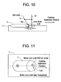
- FIGS. 10 and 11 illustrate an embodiment with the laser beam from the laser 12 aligned with the arc from the heating device 11 in a plane that is aligned in the direction of the cladding application.
- the laser 12 is leading the heating device 11 in the direction of the cladding application.
- FIG. 10 illustrates a side view where the laser beam leads the arc by a longitudinal distance S.
- FIG. 11 illustrates a bird view showing the laser beam impinging on the molten meal pool 20 created by the MIG torch arc.
- FIGS. 12 and 13 illustrate an embodiment similar to the embodiment depicted in FIGS. 10 and 11 but with the arc from the heating device 11 leading the laser beam from the laser 12 in the direction of the cladding application.
- FIG. 12 illustrates a side view while FIG. 5B illustrates a bird view.
- FIGS. 12 and 13 illustrate a continuous application of the metal cladding 3 to the metal base 2 in a U-shape path, which could demonstrate two cases (laser leading and arc leading) mentioned above.
- FIG. 14 illustrates a bird view of the U-shape path of the hybrid laser head movement while FIG. 15 illustrates a side view of that path.
- FIG. 16 illustrates the result of applying the cladding 3 in the U-shape path with the laser beam leading in one leg of the path and the arc leading in the other leg of the path. The result shows the surface of the applied cladding to be uniform in both legs and in the U-transition between the legs.
- FIGS. 12 and 13 illustrate a continuous application of the metal cladding 3 to the metal base 2 in a U-shape path, which could demonstrate two cases (laser leading and arc leading) mentioned above.
- FIG. 14 illustrates a bird view of the U-shape path of the hybrid laser head movement while FIG. 15 illustrates a side view
- the laser power was two kilowatts
- the MIG torch setting was 300 inches per minute feed of cladding material and 25 V in the voltage setting
- the speed of applying the cladding on the metal base was 40 inches per minute
- the MIG gas was Ar+2%O 2
- the metal base 2 was 304 stainless steel
- the cladding 3 was 308 stainless steel.
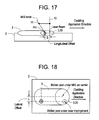
- FIGS. 17 and 18 illustrate an embodiment of the hybrid head 10 where the laser beam longitudinally leads the MIG arc and is laterally offset from the MIG arc with respect to the direction of the cladding application.
- the laser beam leads the MIG arc by the longitudinal distance S and is laterally offset by the distance L.
- FIG. 17 illustrates a side view while FIG. 18 illustrates a bird view.
- FIGS. 19 and 20 illustrate an embodiment similar to the embodiment depicted in FIGS. 17 and 18 but with the arc from the heating device 11 leading the laser beam from the laser 12 in the direction of the cladding application.
- FIG. 19 illustrates a side view while FIG. 20 illustrates a bird view.
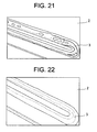
- FIGS. 21 and 22 illustrate results of continuous cladding application using the hybrid head 10 shown in FIGS. 17-20 with a constant longitudinal spacing S of 2.5 mm.
- the applied cladding shown in FIG. 21 was applied with the hybrid head 10 having a lateral offset L of 4.5mm.
- the applied cladding in FIG. 21 exhibits pitting.
- the applied cladding shown in FIG. 22 was applied with the hybrid head having a lateral offset L of 2.5 mm.
- the applied cladding in FIG. 22 exhibits a uniform surface without the pitting shown in FIG. 21 .
- the continuous applied cladding shown in each of FIGS. 21 and 22 was applied with the laser beam leading the arc in one leg of the U-shape path and the arc leading the laser beam in the other leg of the path.
- the applied cladding shown in FIGS. 16 and 21-22 was applied in a U-shape path.
- the metal cladding 3 can be applied to the metal base 2 using other path shapes in which the laser beam may be leading or lagging the arc.
- the path shape includes parallel legs with ninety-degree transitions between the legs.
- the longitudinal distance S between the laser beam and the arc may be zero while the hybrid head 10 applies the cladding 3 in straight parallel legs of the path with the laser beam leading or lagging the arc in the transition between the legs.
- the hybrid head 10 can be configured to maintain a constant geometry of the laser beam and the arc with respect to the direction of cladding application through straight legs and/or through curves. It can also be appreciated that the cladding 3 can be applied to a pipe using the hybrid head 10. To apply the cladding 3 to a pipe, the hybrid head 10 can be configured to maintain a constant linear movement while the pipe simultaneously rotates at a constant rate so that the cladding metal can be built up on the outside diameter of the pipe.
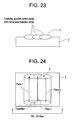
- FIGS. 23 and 24 illustrate a zig-zag path for applying the metal cladding 3 on the metal base 2.
- FIG. 23 illustrates a side view while FIG. 24 illustrates a bird view. With the zig-zag path, the cladding 3 can be applied non-stop on the metal base 2.
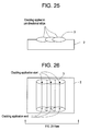
- FIGS. 25 and 26 illustrate a plurality of one-direction paths for applying the metal cladding 3 on the metal base 2.
- FIG. 25 illustrates a side view while FIG. 26 illustrates a bird view.
- the plurality of one-direction paths requires frequent starts and stops of cladding application.
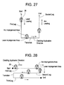
- FIGS. 27 and 28 illustrate embodiments where the geometry of the hybrid head 10 remains fixed with respect to the metal base 2.
- the result of this fixed geometry is that the geometry of the impingement area of the arc and the impingement area of the laser beam remain fixed with respect to the metal base 2.
- the laser beam leads the arc in the first leg while the arc leads the laser beam in the second leg.
- the longitudinal offset between the arc and the laser beam is zero.
- the longitudinal offset between the arc and the laser beam is zero in the first, second and third legs while the laser beam leads the arc in the transitions.
- the hybrid head 10 can be configured to swivel or rotate with respect to the metal base 2 in order for the geometry of the hybrid head 10 to remain fixed with respect to the direction of cladding application (i.e., with respect to each of the legs and transitions).
- multiple laser beams can be used to impinge on various areas of the molten metal pool 20 to improve limiting the temperature gradient.
- the multiple beams can be derived from splitting a laser beam emitted from one laser or from using a plurality of lasers.
- the laser 12 can be configured to oscillate so that the laser beam impinges on the various areas of the molten metal pool 20.
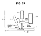
- FIG. 29 illustrates an exemplary embodiment of a beam splitter 130 optically coupled to the laser 12 and configured to split the laser beam emitted from the laser 12 into two or more laser beams that impinge on the molten metal pool 20.
- FIG. 29 illustrates an exemplary embodiment of a controller 132 coupled to the laser 12.
- the controller includes components, such as electronics, sensors, and servos, that are configured to oscillate the laser 12 and the emitted laser beam on various areas of the molten metal pool 20.
- FIG. 14 presents one example of a method 140 for affixing metal cladding to a metal base.
- the method 140 calls for (step 141) heating a surface of the metal base and the metal cladding with a heating device to create a molten metal pool of cladding layered upon metal base material in the metal base. Further, the method 140 calls for (step 142) stabilizing a temperature gradient of the molten metal pool with a laser beam directed into the molten metal pool. Step 142 can include having the laser beam offset to the arc of heating device laterally and/or longitudinally. Further, the method 140 calls for (step 143) cooling the molten metal pool to affix solidified cladding to the metal base.
Landscapes
- Engineering & Computer Science (AREA)
- Physics & Mathematics (AREA)
- Optics & Photonics (AREA)
- Plasma & Fusion (AREA)
- Mechanical Engineering (AREA)
- Laser Beam Processing (AREA)
- Arc Welding In General (AREA)
- Other Surface Treatments For Metallic Materials (AREA)
Abstract
Description
- The subject matter disclosed herein relates to joining a metal cladding to a metal substrate surface.
- Cladding can be applied to a substrate for many reasons. In one or more types of cladding, the substrate is a metal and the cladding is a similar or dissimilar metal. Joining the metal cladding to the metal substrate typically requires melting the cladding and a surface of the metal substrate together to form a molten metal pool and allowing the pool to cool and solidify. The result of the cladding application process is that the metal cladding is firmly affixed to the metal substrate.
- There are many variables involved in the cladding application process such as heat input, cladding width, and cladding deposition rate. In general, these variables must be kept within certain windows in order to prevent defects in the affixed cladding such as non-uniformity and pitting. Some of these variables may be at odds with each other. For example, increasing the cladding deposition rate typically requires a high heat input, which can lead to crack formation. Some of these defects, unfortunately, can require rework or scrapping. Hence, it would be well received in the cladding application art if the rate of cladding deposition could be increased without incurring defects in the affixed cladding.
- According to one aspect, the invention resides in a method for affixing a metal cladding to a metal base including: heating the metal cladding and a surface of the metal base with a heating device to create a molten metal pool having molten metal cladding layered upon molten metal base material in the metal base; stabilizing a temperature gradient of the molten metal pool with a laser beam directed into the molten metal pool; and cooling the molten metal pool to affix solidified cladding to the metal base.
- According to another aspect, the invention resides in an apparatus for applying a metal cladding to a metal base including a heating device configured to heat the cladding and a surface of the metal base to create a molten metal pool having molten metal cladding layered upon molten metal base material in the metal base; and a laser configured to direct a laser beam into the molten metal pool to stabilize a temperature gradient of the molten metal pool.
- These and other advantages and features will become more apparent from the following description taken in conjunction with the drawings.
- Embodiments of the present invention will now be described, by way of example only, with reference to the accompanying drawings in which:
-
FIGS. 1 and 2 illustrate an exemplary embodiment of a hybrid laser head having a heating device and a laser for joining metal cladding to a metal base; -
FIGS. 3-5 depict aspects of joining the cladding to the metal base with a laser beam and arc torch aligned to a same plane perpendicular to a direction of applying the cladding; -
FIGS. 6-9 depict aspects of cladding joined to the metal base using techniques disclosed inFIG. 2 ; -
FIGS. 10 and 11 illustrate an embodiment with the laser beam from the laser aligned with an arc from the heating device in a plane that is aligned in the direction of the cladding application; -
FIGS. 12 and 13 illustrate an embodiment with the arc from the heating device leading the laser beam from the laser in the direction of the cladding application; -
FIGS. 14-16 illustrate a continuous application of the cladding to the metal base in a U-shape path; -
FIGS. 17 and 18 illustrate an embodiment of the hybrid head where the laser beam leads the arc and is laterally offset from the arc with respect to the direction of the cladding application; -
FIGS. 19 and 20 illustrate an embodiment of the hybrid head where the arc leads the laser beam and the laser beam is laterally offset from the arc with respect to the direction of the cladding application; -
FIGS. 21 and 22 illustrate results of continuous cladding application using the hybrid head with the laser beam leading and lagging the arc and being laterally offset from the arc with respect to the direction of the cladding application; -
FIGS. 23 and 24 illustrate a zig-zag path for continuously applying the metal cladding on to the metal base; -
FIGS. 25 and 26 illustrate non-continuously applying the metal cladding to the metal base in a plurality of one-direction paths; -
FIGS. 27 and 28 illustrate two geometries of the arc and laser beam for applying the metal cladding to the metal base; -
FIG. 29 illustrates an exemplary embodiment of a beam splitter and a controller coupled to the laser; and -
FIG. 30 presents one example of a method for applying metal cladding to a metal base. - The detailed description explains embodiments of the invention, together with advantages and features, by way of example with reference to the drawings.
- Disclosed are exemplary embodiments of techniques for joining a metal cladding to a metal substrate or base. The techniques enable a wider strip of cladding to be applied to the metal base at a cladding deposition rate that is faster than prior art methods and yet still provide a uniform cladding surface without an increase in defects.
- The techniques, which include apparatus and method, call for joining the metal cladding to the metal base using a hybrid head for melting the metal cladding and the metal base. The hybrid head includes a heating device and a laser. The heating device such as one used for welding is used to melt the cladding and a surface of the metal base to create a molten metal pool on the surface of the metal base. In the molten metal pool, the melted cladding is layered upon melted base material. The laser produces a laser beam that is directed into the molten metal pool to stabilize the temperature of the molten metal. The laser beam has sufficient power to stabilize the temperature gradient (i.e., reduce variations in temperature) around the laser beam. Stabilized temperature of the molten metal pool enables the rate of deposition of the cladding to be increased over prior art cladding processes and still provides a uniform cladding surface upon solidifying. In addition, the temperature gradient stabilization provides for a wider clad layer than the prior art cladding processes.
- Advantages of the hybrid head over prior art welding techniques for applying cladding include less distortion and less dilution of the cladding with the metal base as a result of the depth of penetration of the molten metal pool.
- The techniques provide various arrangements of the heating device and the laser within the hybrid head as well as various paths that may be used to deposit the cladding on the base.
- Reference may now be had to
FIG. 1 , which illustrates an exemplary embodiment of a hybrid cladding-application head 10 referred to as thehybrid head 10. A simplified representation of thehybrid head 10 is shown inFIG. 1 with ametal base 2 while a drawing of aprototype hybrid head 10 is shown inFIG. 2 with themetal base 2 andmetal cladding 3. Thehybrid head 10 includes aheating device 11 and alaser 12. In one or more embodiments, theheating device 11 is a welding-type torch head. Non-limiting embodiments of the welding-type torch head include torch heads for gas tungsten arc welding (GTAW) also referred to as tungsten inert gas (TIG) welding, gas metal arc welding (GMAW) also referred to as metal inert gas (MIG) welding or metal active gas welding (MAG), submerged arc welding (SAW), plasma arc welding (PAW), and flux core arc welding (FCAW). With the welding-type torch heads, the cladding is generally supplied in the form of a wire, which is melted with the arc that creates the molten metal pool. In one or more embodiments, thelaser 12 is an industrial laser having sufficient power to limit the temperature gradient across the molten metal pool created by theheating device 11, but not over-powering such that the laser beam will not create a keyhole into themetal base 2 deeper than the depth of the molten metal pool. In one or more embodiments, thelaser 12 has sufficient power to maintain the surface area of the molten metal pool while themetal cladding 3 is being deposited on themetal base 2 at a selected rate. It can be appreciated that the speed of the cladding deposition and size and temperature of the molten metal pool are just some factors that can be used to determine the required power output of thelaser 12. Non-limiting embodiments of thelaser 12 include a Nd:YAG laser, a CO2 laser, a disk laser, a fibre laser, or any type of laser resonator of sufficient power to stabilize the temperature gradient of the molten metal pool. Referring toFIG. 1 , thelaser 12 can be oriented to lead theheating device 11 in depositing thecladding 3 on themetal base 2. Alternatively, theheating device 11 can be oriented to lead thelaser 12 in the cladding application process. - Reference may now be had to
FIGS. 3-5 , which illustrate a laser beam from thelaser 12 and an arc from theheating device 11 aligned to a same plane perpendicular to the direction of cladding application. It can be appreciated that during the cladding application process themetal base 2 can be moved with respect to thehybrid head 10 or thehybrid head 10 can be moved with respect to themetal base 2.FIG. 3 illustrates a side view of the laser beam aligned with the arc.FIG. 4 illustrates a bird view of the laser beam and the arc over amolten metal pool 20. The laser beam is laterally offset a distance L from the arc.FIG. 5 illustrates a side view of the laser beam and the arc. InFIG. 5 , the direction of cladding application is towards the viewer. - Reference may now be had to
FIGS. 6-9 , which illustrate results of cladding application using the embodiment disclosed inFIGS. 3-5 with different offsets L between the laser beam and the arc. The power of thelaser 12 was two kilowatts. Theheating device 11 was a MIG welding torch with settings of 300 inches per minute feed of cladding material to the torch and 25V in the voltage setting. The speed of application of thecladding 3 to thebase 2 was forty inches per minute. Gas used by the MIG torch was Ar+2%O2. Themetal base 2 was 304 stainless steel and themetal cladding 3 was 308 stainless steel. InFIG. 6 , the spacing L was 5.0 mm. Two separate beads of thecladding 3 were obtained. No interaction occurred between the MIG torch arc and the laser beam resulting in a first molten metal pool under the laser beam and a second molten metal pool under the MIG torch arc. A uniform cladding bead under the laser beam was obtained while the cladding bead under the MIG torch arc exhibits clumps. InFIG. 7 , the spacing L was 4.0 mm and one cladding bead was obtained, but with clumps of thecladding 3. InFIG. 8 , the spacing L was 2.5mm and one cladding bead was obtained with less clumps of thecladding 3 than when L was 4.0 mm. InFIG. 9 , the spacing L was 1.0 mm and the resulting cladding bead had a uniform surface on the laser beam side of the cladding beam, which indicates that the laser beam aligned with the arc only in the lateral direction cannot produce a uniform clad surface. - Reference may now be had to
FIGS. 10 and 11 , which illustrate an embodiment with the laser beam from thelaser 12 aligned with the arc from theheating device 11 in a plane that is aligned in the direction of the cladding application. In the embodiment ofFIGS. 10 and 11 , thelaser 12 is leading theheating device 11 in the direction of the cladding application.FIG. 10 illustrates a side view where the laser beam leads the arc by a longitudinal distance S.FIG. 11 illustrates a bird view showing the laser beam impinging on themolten meal pool 20 created by the MIG torch arc. - Reference may now be had to
FIGS. 12 and 13 , which illustrate an embodiment similar to the embodiment depicted inFIGS. 10 and 11 but with the arc from theheating device 11 leading the laser beam from thelaser 12 in the direction of the cladding application.FIG. 12 illustrates a side view whileFIG. 5B illustrates a bird view. - Reference may now be had to
FIGS. 12 and 13 , which illustrate a continuous application of themetal cladding 3 to themetal base 2 in a U-shape path, which could demonstrate two cases (laser leading and arc leading) mentioned above.FIG. 14 illustrates a bird view of the U-shape path of the hybrid laser head movement whileFIG. 15 illustrates a side view of that path.FIG. 16 illustrates the result of applying thecladding 3 in the U-shape path with the laser beam leading in one leg of the path and the arc leading in the other leg of the path. The result shows the surface of the applied cladding to be uniform in both legs and in the U-transition between the legs. In the embodiment ofFIGS. 14-16 , the laser power was two kilowatts, the MIG torch setting was 300 inches per minute feed of cladding material and 25 V in the voltage setting, the speed of applying the cladding on the metal base was 40 inches per minute, the MIG gas was Ar+2%O2 themetal base 2 was 304 stainless steel, and thecladding 3 was 308 stainless steel. - Reference may now be had to
FIGS. 17 and 18 , which illustrate an embodiment of thehybrid head 10 where the laser beam longitudinally leads the MIG arc and is laterally offset from the MIG arc with respect to the direction of the cladding application. InFIGS. 17 and 18 , the laser beam leads the MIG arc by the longitudinal distance S and is laterally offset by the distance L.FIG. 17 illustrates a side view whileFIG. 18 illustrates a bird view. - Reference may now be had to
FIGS. 19 and 20 , which illustrate an embodiment similar to the embodiment depicted inFIGS. 17 and 18 but with the arc from theheating device 11 leading the laser beam from thelaser 12 in the direction of the cladding application.FIG. 19 illustrates a side view whileFIG. 20 illustrates a bird view. - Reference may now be had to
FIGS. 21 and 22 , which illustrate results of continuous cladding application using thehybrid head 10 shown inFIGS. 17-20 with a constant longitudinal spacing S of 2.5 mm. The applied cladding shown inFIG. 21 was applied with thehybrid head 10 having a lateral offset L of 4.5mm. The applied cladding inFIG. 21 exhibits pitting. The applied cladding shown inFIG. 22 was applied with the hybrid head having a lateral offset L of 2.5 mm. The applied cladding inFIG. 22 exhibits a uniform surface without the pitting shown inFIG. 21 . The continuous applied cladding shown in each ofFIGS. 21 and 22 was applied with the laser beam leading the arc in one leg of the U-shape path and the arc leading the laser beam in the other leg of the path. - The applied cladding shown in
FIGS. 16 and21-22 was applied in a U-shape path. It can be appreciated that themetal cladding 3 can be applied to themetal base 2 using other path shapes in which the laser beam may be leading or lagging the arc. In one or more embodiments, the path shape includes parallel legs with ninety-degree transitions between the legs. In one or more embodiments, the longitudinal distance S between the laser beam and the arc may be zero while thehybrid head 10 applies thecladding 3 in straight parallel legs of the path with the laser beam leading or lagging the arc in the transition between the legs. It can be appreciated that thehybrid head 10 can be configured to maintain a constant geometry of the laser beam and the arc with respect to the direction of cladding application through straight legs and/or through curves. It can also be appreciated that thecladding 3 can be applied to a pipe using thehybrid head 10. To apply thecladding 3 to a pipe, thehybrid head 10 can be configured to maintain a constant linear movement while the pipe simultaneously rotates at a constant rate so that the cladding metal can be built up on the outside diameter of the pipe. -
FIGS. 23 and 24 illustrate a zig-zag path for applying themetal cladding 3 on themetal base 2.FIG. 23 illustrates a side view whileFIG. 24 illustrates a bird view. With the zig-zag path, thecladding 3 can be applied non-stop on themetal base 2. -
FIGS. 25 and 26 illustrate a plurality of one-direction paths for applying themetal cladding 3 on themetal base 2.FIG. 25 illustrates a side view whileFIG. 26 illustrates a bird view. The plurality of one-direction paths requires frequent starts and stops of cladding application. -
FIGS. 27 and 28 illustrate embodiments where the geometry of thehybrid head 10 remains fixed with respect to themetal base 2. The result of this fixed geometry is that the geometry of the impingement area of the arc and the impingement area of the laser beam remain fixed with respect to themetal base 2. InFIG. 27 , the laser beam leads the arc in the first leg while the arc leads the laser beam in the second leg. In the transition, the longitudinal offset between the arc and the laser beam is zero. InFIG. 28 , the longitudinal offset between the arc and the laser beam is zero in the first, second and third legs while the laser beam leads the arc in the transitions. It can be appreciated that thehybrid head 10 can be configured to swivel or rotate with respect to themetal base 2 in order for the geometry of thehybrid head 10 to remain fixed with respect to the direction of cladding application (i.e., with respect to each of the legs and transitions). - It was shown above that using a laser beam of sufficient power that impinges on the
molten metal pool 20 will stabilize the temperature gradient of thepool 20 to enable increasing the rate of application of themetal cladding 3 on themetal base 2 and to enable increasing the width of cladding application with respect to prior art cladding application processes. It can be appreciated that multiple laser beams can be used to impinge on various areas of themolten metal pool 20 to improve limiting the temperature gradient. The multiple beams can be derived from splitting a laser beam emitted from one laser or from using a plurality of lasers. It can be appreciated that thelaser 12 can be configured to oscillate so that the laser beam impinges on the various areas of themolten metal pool 20.FIG. 29 illustrates an exemplary embodiment of abeam splitter 130 optically coupled to thelaser 12 and configured to split the laser beam emitted from thelaser 12 into two or more laser beams that impinge on themolten metal pool 20. In addition,FIG. 29 illustrates an exemplary embodiment of acontroller 132 coupled to thelaser 12. The controller includes components, such as electronics, sensors, and servos, that are configured to oscillate thelaser 12 and the emitted laser beam on various areas of themolten metal pool 20. -
FIG. 14 presents one example of amethod 140 for affixing metal cladding to a metal base. Themethod 140 calls for (step 141) heating a surface of the metal base and the metal cladding with a heating device to create a molten metal pool of cladding layered upon metal base material in the metal base. Further, themethod 140 calls for (step 142) stabilizing a temperature gradient of the molten metal pool with a laser beam directed into the molten metal pool. Step 142 can include having the laser beam offset to the arc of heating device laterally and/or longitudinally. Further, themethod 140 calls for (step 143) cooling the molten metal pool to affix solidified cladding to the metal base. - Elements of the embodiments have been introduced with either the articles "a" or "an." The articles are intended to mean that there are one or more of the elements. The terms "including" and "having" are intended to be inclusive such that there may be additional elements other than the elements listed. The conjunction "or" when used with a list of at least two terms is intended to mean any term or combination of terms. The terms "first" and "second" are used to distinguish elements and are not used to denote a particular order. The term "couple" relates to one component being coupled either directly to another component or indirectly to the another component via one or more intermediate components.
- While the invention has been described in detail in connection with only a limited number of embodiments, it should be readily understood that the invention is not limited to such disclosed embodiments. Rather, the invention can be modified to incorporate any number of variations, alterations, substitutions or equivalent arrangements not heretofore described, but which are commensurate with the spirit and scope of the invention. Additionally, while various embodiments of the invention have been described, it is to be understood that aspects of the invention may include only some of the described embodiments. Accordingly, the invention is not to be seen as limited by the foregoing description, but is only limited by the scope of the appended claims.
Claims (16)
- A method for affixing a metal cladding (3) to a metal base (2), the method comprising:heating metal cladding (3) and a surface of the metal base (2) with a heating device (11) to create a molten metal pool (20) having molten metal cladding layered upon molten metal base material in the metal base (2);stabilizing a temperature gradient of the molten metal pool (20) with a laser beam directed into the molten metal pool (20); andcooling the molten metal pool (20) to affix the metal cladding (3) to the metal base (2).
- The method according to claim 1, wherein the heating device (11) uses an arc to create the molten metal pool (20).
- The method according to claim 2, wherein the laser beam is longitudinally offset a distance S from the arc in a direction parallel to a direction of application of the metal cladding (3).
- The method according to claim 3, wherein the laser beam is laterally offset from the arc a distance L in a direction perpendicular to the direction of application of the metal cladding (3).
- The method according to any of claims 1 to 4, wherein the laser beam has sufficient power to maintain a constant surface area of the molten metal pool (20) as the metal cladding (3) is being applied to the molten metal pool (20).
- The method according to any preceding claim, wherein the heating device (11) and the arc are arranged so that a common molten metal pool (20) is created and maintained.
- The method according to claim 6, wherein the apparatus is configured so that one or more filler metals can be fed into the common molten metal pool (20) for the cladding (3).
- The method according to any preceding claim, further comprising oscillating an impingement area of the laser beam within the molten metal pool (20).
- The method according to any preceding claim, wherein stabilizing comprises directing multiple laser beams into the molten metal pool (20).
- The method according to any preceding claim, wherein each of the laser beams is directed into a different area of the molten metal pool (20).
- An apparatus for applying a metal cladding (3) to a metal base (2), the apparatus comprising:a heating device (11) configured to heat metal cladding (3) and a surface of the metal base (2) to create a molten metal pool (20) having molten metal cladding (3) layered upon molten metal base (2) material in the metal base (2); anda laser (12) configured to direct a laser beam into the molten metal pool (20) to stabilize a temperature gradient of the molten metal pool (20).
- The apparatus according to claim 11, wherein the heating device (11) is configured to establish an arc to create the molten metal pool (20).
- The apparatus according to claim 11 or 12, wherein the apparatus is configured so that the heating device (11) and the laser (12) maintain a fixed geometry with respect to an orientation of the metal base (2) and/or to a direction of application of the metal cladding (3).
- The apparatus according to any of claims 11 to 13, wherein the heating device (11) and the laser (12) are configured to move longitudinally along a pipe while the pipe rotates to deposit the metal cladding (3) spirally on an outside surface of the pipe.
- The apparatus according to any of claims 11 to 14, further comprising a beam splitter (130) optically coupled the laser (12) to create a plurality of laser beams directed into the molten metal pool.
- The apparatus according to any of claims 11 to 15, further comprising a controller (132) configured to oscillate impingement of the laser beam in the molten metal pool (20).
Applications Claiming Priority (1)
| Application Number | Priority Date | Filing Date | Title |
|---|---|---|---|
| US13/048,289 US8895886B2 (en) | 2011-03-15 | 2011-03-15 | Cladding application method and apparatus using hybrid laser process |
Publications (2)
| Publication Number | Publication Date |
|---|---|
| EP2500127A2 true EP2500127A2 (en) | 2012-09-19 |
| EP2500127A3 EP2500127A3 (en) | 2017-12-27 |
Family
ID=45939117
Family Applications (1)
| Application Number | Title | Priority Date | Filing Date |
|---|---|---|---|
| EP12158499.9A Withdrawn EP2500127A3 (en) | 2011-03-15 | 2012-03-07 | Cladding application method and apparatus using hybrid laser process |
Country Status (4)
| Country | Link |
|---|---|
| US (1) | US8895886B2 (en) |
| EP (1) | EP2500127A3 (en) |
| JP (1) | JP6169818B2 (en) |
| CN (1) | CN102677042A (en) |
Cited By (1)
| Publication number | Priority date | Publication date | Assignee | Title |
|---|---|---|---|---|
| CN112453826A (en) * | 2020-11-17 | 2021-03-09 | 西安热工研究院有限公司 | Turbine blade crack welding repair method capable of refining tissue |
Families Citing this family (10)
| Publication number | Priority date | Publication date | Assignee | Title |
|---|---|---|---|---|
| US9352413B2 (en) * | 2011-01-13 | 2016-05-31 | Siemens Energy, Inc. | Deposition of superalloys using powdered flux and metal |
| US9126287B2 (en) * | 2012-03-12 | 2015-09-08 | Siemens Energy, Inc. | Advanced pass progression for build-up welding |
| US20130309000A1 (en) * | 2012-05-21 | 2013-11-21 | General Electric Comapny | Hybrid laser arc welding process and apparatus |
| US9586289B2 (en) | 2014-04-30 | 2017-03-07 | Alabama Specialty Products, Inc. | Cladding apparatus and method |
| CN110167755B (en) | 2017-01-05 | 2022-04-08 | Ipg光子公司 | Additive laser processing system and method |
| CN109079327A (en) * | 2018-09-05 | 2018-12-25 | 大连理工大学 | Aluminum alloy laser-double pulse MIG composite heat source arc additive manufacturing method and workpiece |
| CN114040827B (en) * | 2019-07-08 | 2023-06-09 | 三菱电机株式会社 | Additive manufacturing device |
| US20210031297A1 (en) * | 2019-08-01 | 2021-02-04 | GM Global Technology Operations LLC | System and method for multi-task laser welding |
| CN113275754A (en) * | 2020-02-18 | 2021-08-20 | 空客(北京)工程技术中心有限公司 | Additive manufacturing system and additive manufacturing method |
| CN115302053B (en) * | 2022-08-29 | 2023-11-14 | 中建安装集团有限公司 | Intelligent submerged arc welding method for stainless steel composite plate |
Family Cites Families (25)
| Publication number | Priority date | Publication date | Assignee | Title |
|---|---|---|---|---|
| JPS62183983A (en) * | 1986-02-07 | 1987-08-12 | Nippon Kokan Kk <Nkk> | Laser crazing method |
| US5985056A (en) * | 1996-01-15 | 1999-11-16 | The University Of Tennessee Research Corporation | Method for laser induced improvement of surfaces |
| US6191379B1 (en) * | 1999-04-05 | 2001-02-20 | General Electric Company | Heat treatment for weld beads |
| US6191386B1 (en) | 1999-04-22 | 2001-02-20 | The Ohio State University | Method and apparatus for initiating, directing and constricting electrical discharge arcs |
| US6521861B2 (en) * | 2000-02-07 | 2003-02-18 | General Electric Company | Method and apparatus for increasing welding rate for high aspect ratio welds |
| JP2001246465A (en) * | 2000-03-06 | 2001-09-11 | Mitsubishi Heavy Ind Ltd | Gas shielded-system arc welding method |
| WO2003102260A2 (en) * | 2002-06-04 | 2003-12-11 | Preco Laser Systems, Llc | High energy beam cladding |
| JP2004298896A (en) * | 2003-03-28 | 2004-10-28 | Jfe Engineering Kk | Groove processing method and laser / arc combined welding method |
| DE102004026228B4 (en) * | 2004-05-28 | 2007-06-28 | Airbus Deutschland Gmbh | Titanium-aluminum component |
| JP2006095559A (en) * | 2004-09-29 | 2006-04-13 | Daihen Corp | Laser irradiation arc welding method |
| JP2006224130A (en) * | 2005-02-16 | 2006-08-31 | Nippon Steel Corp | Combined welding with laser and mag arc |
| WO2006133034A1 (en) * | 2005-06-06 | 2006-12-14 | Mts Systems Corporation | Direct metal deposition using laser radiation and electric arc |
| CN100425384C (en) * | 2006-02-15 | 2008-10-15 | 机械科学研究院哈尔滨焊接研究所 | Method for connecting heterogeneous metals by large-facula laser and electric arc combined heat source |
| US8242410B2 (en) * | 2006-07-14 | 2012-08-14 | Lincoln Global, Inc. | Welding methods and systems |
| DE102006048580C5 (en) * | 2006-10-13 | 2015-02-19 | Fraunhofer-Gesellschaft zur Förderung der angewandten Forschung e.V. | Method and device for crack-free welding, repair welding or build-up welding of hot crack susceptible materials |
| DE102007022863B4 (en) * | 2007-05-15 | 2010-07-22 | Meyer Werft Gmbh | Process for the non-detachable joining of components made of heat-meltable, metallic material |
| US8278587B2 (en) * | 2008-02-11 | 2012-10-02 | Adaptive Intelligent Systems, LLC | Systems and methods to modify gas metal arc welding and its variants |
| US8257049B2 (en) * | 2008-04-25 | 2012-09-04 | Caterpillar Inc. | Process for building up an edge of a machine component, and machine component remanufacturing strategy |
| WO2010021094A1 (en) * | 2008-08-19 | 2010-02-25 | パナソニック株式会社 | Composite welding method and composite welding device |
| JP5375527B2 (en) * | 2008-10-31 | 2013-12-25 | Jfeスチール株式会社 | Laser welded steel pipe manufacturing method |
| CN101811231B (en) * | 2009-02-20 | 2011-08-17 | 机械科学研究院哈尔滨焊接研究所 | Method for welding with laser-cold metal transferred arc composite heat source |
| JP5446340B2 (en) * | 2009-03-11 | 2014-03-19 | パナソニック株式会社 | Composite welding apparatus and composite welding method |
| US20100326962A1 (en) * | 2009-06-24 | 2010-12-30 | General Electric Company | Welding control system |
| GB201006348D0 (en) * | 2010-04-16 | 2010-06-02 | Rolls Royce Plc | Method of manufacturing a component |
| US8253060B2 (en) * | 2010-06-30 | 2012-08-28 | General Electric Company | Hybrid laser arc welding process and apparatus |
-
2011
- 2011-03-15 US US13/048,289 patent/US8895886B2/en not_active Expired - Fee Related
-
2012
- 2012-03-07 EP EP12158499.9A patent/EP2500127A3/en not_active Withdrawn
- 2012-03-08 JP JP2012051073A patent/JP6169818B2/en not_active Expired - Fee Related
- 2012-03-15 CN CN2012100794986A patent/CN102677042A/en active Pending
Non-Patent Citations (1)
| Title |
|---|
| None |
Cited By (2)
| Publication number | Priority date | Publication date | Assignee | Title |
|---|---|---|---|---|
| CN112453826A (en) * | 2020-11-17 | 2021-03-09 | 西安热工研究院有限公司 | Turbine blade crack welding repair method capable of refining tissue |
| CN112453826B (en) * | 2020-11-17 | 2021-12-21 | 西安热工研究院有限公司 | A Welding Repair Method for Turbine Blade Cracks with Microstructure Refinement |
Also Published As
| Publication number | Publication date |
|---|---|
| JP2012192452A (en) | 2012-10-11 |
| CN102677042A (en) | 2012-09-19 |
| US8895886B2 (en) | 2014-11-25 |
| EP2500127A3 (en) | 2017-12-27 |
| US20120234798A1 (en) | 2012-09-20 |
| JP6169818B2 (en) | 2017-07-26 |
Similar Documents
| Publication | Publication Date | Title |
|---|---|---|
| US8895886B2 (en) | Cladding application method and apparatus using hybrid laser process | |
| JP6159147B2 (en) | Hybrid laser arc welding process and apparatus | |
| JP5496152B2 (en) | Combined welding method of laser welding and arc welding of T type joint | |
| JP5873658B2 (en) | Hybrid laser arc welding process and apparatus | |
| EP2511041B1 (en) | A hybrid welding apparatus and system and method of welding | |
| EP2698223B1 (en) | A process of welding to repair thick sections using two arc welding devices and a laser device | |
| JP5601003B2 (en) | Laser arc combined welding method and butt welding metal plate groove | |
| EP2596896B1 (en) | Welding system and process with a laser device, a GMAW device and a GTAW device | |
| CN114867577B (en) | Joining method | |
| JP5318543B2 (en) | Laser-arc combined welding method | |
| US8853594B2 (en) | Welding method and apparatus therefor | |
| JP5416422B2 (en) | Laser-arc combined welding method | |
| KR20190002760A (en) | Oscillating welding method | |
| EP2783788B1 (en) | Welding process and welding system | |
| JP2009255172A (en) | Method for manufacturing t-type joint | |
| Victor | Hybrid laser arc welding | |
| KR20230121147A (en) | Laser Brazing Joining Method | |
| JP5303112B2 (en) | MIG welding method | |
| JPH07246484A (en) | Laser beam welding method | |
| JP2011147944A (en) | Laser/arc composite welding method | |
| Thomy et al. | Fibre laser GMA hybrid welding of thin sheet material | |
| Reutzel et al. | Experimental analysis of practical aspects of hybrid welding of thick sections |
Legal Events
| Date | Code | Title | Description |
|---|---|---|---|
| PUAI | Public reference made under article 153(3) epc to a published international application that has entered the european phase |
Free format text: ORIGINAL CODE: 0009012 |
|
| AK | Designated contracting states |
Kind code of ref document: A2 Designated state(s): AL AT BE BG CH CY CZ DE DK EE ES FI FR GB GR HR HU IE IS IT LI LT LU LV MC MK MT NL NO PL PT RO RS SE SI SK SM TR |
|
| AX | Request for extension of the european patent |
Extension state: BA ME |
|
| PUAL | Search report despatched |
Free format text: ORIGINAL CODE: 0009013 |
|
| AK | Designated contracting states |
Kind code of ref document: A3 Designated state(s): AL AT BE BG CH CY CZ DE DK EE ES FI FR GB GR HR HU IE IS IT LI LT LU LV MC MK MT NL NO PL PT RO RS SE SI SK SM TR |
|
| AX | Request for extension of the european patent |
Extension state: BA ME |
|
| RIC1 | Information provided on ipc code assigned before grant |
Ipc: B23K 26/14 20140101AFI20171123BHEP Ipc: B23K 26/34 20140101ALI20171123BHEP |
|
| 17P | Request for examination filed |
Effective date: 20180627 |
|
| RBV | Designated contracting states (corrected) |
Designated state(s): AL AT BE BG CH CY CZ DE DK EE ES FI FR GB GR HR HU IE IS IT LI LT LU LV MC MK MT NL NO PL PT RO RS SE SI SK SM TR |
|
| STAA | Information on the status of an ep patent application or granted ep patent |
Free format text: STATUS: THE APPLICATION IS DEEMED TO BE WITHDRAWN |
|
| 18D | Application deemed to be withdrawn |
Effective date: 20190824 |