EP2499712B1 - Halter zum positionsfesten halten länglicher objekte relativ zu einer struktur - Google Patents
Halter zum positionsfesten halten länglicher objekte relativ zu einer struktur Download PDFInfo
- Publication number
- EP2499712B1 EP2499712B1 EP10795424.0A EP10795424A EP2499712B1 EP 2499712 B1 EP2499712 B1 EP 2499712B1 EP 10795424 A EP10795424 A EP 10795424A EP 2499712 B1 EP2499712 B1 EP 2499712B1
- Authority
- EP
- European Patent Office
- Prior art keywords
- mounting
- parts
- ramp
- support
- bearing
- Prior art date
- Legal status (The legal status is an assumption and is not a legal conclusion. Google has not performed a legal analysis and makes no representation as to the accuracy of the status listed.)
- Not-in-force
Links
Images


Classifications
-
- H—ELECTRICITY
- H02—GENERATION; CONVERSION OR DISTRIBUTION OF ELECTRIC POWER
- H02G—INSTALLATION OF ELECTRIC CABLES OR LINES, OR OF COMBINED OPTICAL AND ELECTRIC CABLES OR LINES
- H02G3/00—Installations of electric cables or lines or protective tubing therefor in or on buildings, equivalent structures or vehicles
- H02G3/22—Installations of cables or lines through walls, floors or ceilings, e.g. into buildings
-
- F—MECHANICAL ENGINEERING; LIGHTING; HEATING; WEAPONS; BLASTING
- F16—ENGINEERING ELEMENTS AND UNITS; GENERAL MEASURES FOR PRODUCING AND MAINTAINING EFFECTIVE FUNCTIONING OF MACHINES OR INSTALLATIONS; THERMAL INSULATION IN GENERAL
- F16L—PIPES; JOINTS OR FITTINGS FOR PIPES; SUPPORTS FOR PIPES, CABLES OR PROTECTIVE TUBING; MEANS FOR THERMAL INSULATION IN GENERAL
- F16L3/00—Supports for pipes, cables or protective tubing, e.g. hangers, holders, clamps, cleats, clips, brackets
- F16L3/24—Supports for pipes, cables or protective tubing, e.g. hangers, holders, clamps, cleats, clips, brackets with a special member for attachment to profiled girders
- F16L3/243—Supports for pipes, cables or protective tubing, e.g. hangers, holders, clamps, cleats, clips, brackets with a special member for attachment to profiled girders the special member being inserted in the profiled girder
-
- H—ELECTRICITY
- H02—GENERATION; CONVERSION OR DISTRIBUTION OF ELECTRIC POWER
- H02G—INSTALLATION OF ELECTRIC CABLES OR LINES, OR OF COMBINED OPTICAL AND ELECTRIC CABLES OR LINES
- H02G3/00—Installations of electric cables or lines or protective tubing therefor in or on buildings, equivalent structures or vehicles
- H02G3/30—Installations of cables or lines on walls, floors or ceilings
- H02G3/32—Installations of cables or lines on walls, floors or ceilings using mounting clamps
-
- H—ELECTRICITY
- H02—GENERATION; CONVERSION OR DISTRIBUTION OF ELECTRIC POWER
- H02G—INSTALLATION OF ELECTRIC CABLES OR LINES, OR OF COMBINED OPTICAL AND ELECTRIC CABLES OR LINES
- H02G3/00—Installations of electric cables or lines or protective tubing therefor in or on buildings, equivalent structures or vehicles
- H02G3/36—Installations of cables or lines in walls, floors or ceilings
Definitions
- the present invention relates to a support for holding in position elongated objects, such as tubes, ducts, cables, etc. with respect to a structure such as a crossmember or a beam, said support comprising at least one support piece for maintaining said elongate objects oriented in a selected direction through holding means and fastening means such as a clamp.
- the electric cable bundles are generally held by holding elements, for example clamps on supports, themselves fixed on structural elements, such as fuselage frames or floor rails.
- These supports which are generally light alloy sheets, are riveted or screwed onto the structure of the aircraft. Often these supports can not adapt to all structures.
- the supports and collars currently used are not far enough apart to prevent said cables from rubbing against the beams or frames. Such contact by friction, in particular in a vibratory environment, can lead to wear of the sheaths of these electric cables, and cause disturbances in the operation of the electrical circuits connected to said cables, such as signal losses or short circuits.
- the present invention provides a novel support for holding in place a cable or bundle of electrical cables or other elongated object, at least partially solving at least one of the above problems.
- the support for holding at least one elongated object according to the invention is simpler in its operating mode while ensuring better support for elongated objects.
- Another object of the invention is to provide a support having a greater modularity in terms of fixing area on the structure and shape of the structure relative to existing supports.
- the invention relates to a support for holding in position an elongated object such as an electric cable with respect to a structure, according to claim 1.
- the bearing surfaces of the structure are substantially planar, at least one opening being arranged in the structure for passing said elongate object.
- the connecting pieces are configured so as to tighten at least partially around the opening.
- each of the two pieces is in the form of a half-cradle which at least partially squeezes the periphery of the opening, the two assembled half-cradles defining an orifice through which the cradle is received. elongated object.
- the support consisting of two half-cradles that define the orifice through which pass through electrical cables, practically eliminates the risk of contact friction of these cables against the edge of the structure.
- one of the two connecting pieces comprises at least one projection and the other piece comprises at least one corresponding recess, said projections and said corresponding recesses cooperating together to block said two parts against each other. bearing surfaces of the structure.
- the two connecting pieces comprise holes allowing the passage of the clamping means such as clamps to block said two parts against the bearing surfaces of the structure.
- the two parts may comprise locking means for locking the parts in position on the structure to provide a better attachment of the support on the structure in a vibratory environment.
- Said ramp-shaped support piece has an end secured to at least one of the two connecting pieces.
- the elongated object may be held at a distance from the upper surface of the ramp and the edge of the orifice to avoid friction which could cause wear of the elongated object.
- said holding means form a substantially closed surface such as a clamp or hoop intended to surround the outer contour of the elongate objects.
- the two connecting pieces are in the form of a pair of flanges, said flanges having an edge having a substantially curved shape and an edge extended by an extension. Holes are provided on the ends of the flanges and the extension to receive a clamping means for assembling the two flanges against each other against the structure.
- the holding means are in the form of a clipper module comprising a first fixing lug configured to snap on said ramp and at least a second fixing lug for fixing the object elongated by means of fixing means.
- said first fixing lug has a concave open surface adapted to snap onto the ramp.
- holes are provided in said first end and the flanges to allow the passage of a fastening means such as a clamp.
- said second fixing lug forms a ball joint for orienting the elongated object in the chosen direction.
- this ball joint is constituted by a substantially circular piece provided at its center with a projection having a spherical contact surface, said surface cooperating with a corresponding spherical concave surface of a movable fixing element. Holes are provided on the periphery of said workpiece and the movable securing member for passing a fastening means for securing the movable member to the spherical surface once the direction in which the elongate object is to be held is chosen.
- said second fixing lug forms a fastener comprising at least one hole for receiving the fixing means.
- the support comprises a set of two intermediate support pieces intended to be interposed between two fasteners belonging to two separate supports, the two intermediate parts being slidably mounted relative to each other. the other to adjust the length of said set.
- the assembly comprises a female ramp having a substantially cylindrical shape, the elongate object being held in position on said ramp by fixing means.
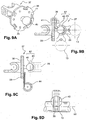
- the support 1 for holding in position an elongate object with respect to a structure, according to the first embodiment of the invention is shown on the Figures 1, 2A and 2B .
- Figures 1, 2A and 2B show clamping means particularly adapted to the supports according to the invention.
- the ramps associated with the supports of the invention have not been shown in these figures.
- the ramps as described with the aid of the other figures, and in particular Figures 6A and 6B are easily transposed to the support of Figures 1, 2A and 2B .
- the clamping means described in association with the support of Figures 1 to 5B are easily transposed to the support of Figures 6A and 6B .
- the support according to the invention is particularly suitable for holding in position elongate objects such as tubes, ducts, cables, etc.
- the structure which is, for example, a fuselage frame or a floor cross member is delimited by two surfaces. substantially flat and at least substantially parallel. An opening is generally made in the thickness of this structure to pass the cables.
- the support 1 comprises two connecting pieces 2, 3 arranged on either side of the structure.
- the two connecting pieces 2, 3 are each in the form of half-cradle flanges.
- Each of said parts 2, 3 comprises a bearing face 2a, 3a which bear against a surface corresponding support of the structure, thereby tightening at least partially the periphery of the opening.
- the two assembled parts thus define an orifice through which the cables pass.
- the periphery of said two parts 2, 3 is provided with corresponding projections 7 and recesses 8 which cooperate together to lock them against the bearing surfaces of the structure.
- Each of the two parts 2, 3 comprises two fixing lugs 61, 62, arranged diametrically opposite. These fixing lugs are substantially circular.
- each of the lugs 61, 62 has a lug 5.
- the fixing lugs 61, 62 of the second part 2 and the structure comprise holes 6 to allow the insertion of the lug 5.
- a locking cap is adapted to cooperate with the lug to lock the support in position on the structure.
- FIGS. 4A, 4B, 5A and 5B illustrate two particular embodiments of this locking mechanism.
- the lug 5 comprises a groove 17 and the locking cap 16 a protrusion 18, of corresponding shape, so that this projection is introduced into the groove to ensure blocking.
- the lug 5 has a projection 19 and the locking plug 16 has a corresponding recess 20 for coming to lock on said projection 19.
- the plug 16 is inserted into the holes 6 in a position in which the recess 20 is not in abutment position against the projection 19, and then rotates 90 ° of the plug 16 to move said cap 16 in a locking position.
- the support 1 is then held tight against the structure thanks to the projections 7 and the hollow 8, the locking means 5, 16 make it possible to secure the fixation even when the effects of the vibration make the clamping of the two half-cradles 2, 3 less effective.
- FIGS. 2A and 2B show an alternative form of clamping means of the two half-cradles 2, 3 against structure.
- Each of said half-cradles 2, 3 has holes 11 made on the peripheral edges.
- clamping means 10 such as a hoop make it possible to clamp the two half-cradles 2, 3 against each other.
- these clamping means 10 are constituted for example by a collar provided with marked positions 10a which cooperate with a locking element 10b.
- Other shapes or means equivalent to the collar as shown can also be used.
- the support also comprises a support piece 4 adapted to hold and fix the cable or any other elongated object transversely to the lateral surfaces 12a, 12b of the structure.
- the elongated objects such as the cables are made integral with said support 1 by means of holding means 50 such as a clamp ( Fig. 3 ).
- the two flanges 21, 22 each comprise a substantially curved edge 21b, 22b and an extension 25, 29.
- a hole 26 is provided for this purpose on the extensions and on the structure to pass a conventional clamping means 10 as described in the Figure 2A .
- the hole 26 is formed on the bisector of the two bearing points (located at the two opposite ends of the flanges 21, 22) and at a distance proportional to the geometry of the element, so as not to generate of crack in the structure.
- each of the flanges 21, 22 is provided at each of its ends with an extension 52 (only one visible on the Figures 6A and 6B ) radially projecting from the corresponding bearing surface 21a, 22a.
- the extensions are for example of complementary cylindrical circular shapes, so that the extensions of one of the two flanges 21, 22 fit into the extensions 52 of the second flange 21, 22.
- the ends of the flanges also include a hole 27, 28 for receiving a conventional clamping means for holding the two flanges together.
- a first insert 55 is introduced into the orifice of the second extension 54, of smaller diameter, of a first side 12a of the wall 12 along which the flange 22 is joined.
- a second insert 56 is inserted into the orifice 28 on the other side 12b of the wall 12, said second insert 56 being screwed into the first insert 55.
- the figure 7 illustrates an example of fixing the two flanges 21, 22 on the edge 51 of an opening 15 made in a structure. From the description that has just been made, it is easily understood that by their shape, the two flanges can also be fixed on the edge of a structure such as the edge of a frame or a floor cross. It is therefore no longer necessary to make an opening in the structure to pass the elongated object or objects, thus not leading to a reduction of the mechanical properties of the structure. In addition, the cable paths are no longer imposed by the structures, the installation of the cables is made more flexible.
- the two parts 23, 24 are in the form of a ramp having a substantially cylindrical shape of circular section and curved to match the shape of the flanges. These ramps are secured to the flanges by any conventional means, especially by gluing.
- the cylindrical ramps may have another section, including a square section, oval and so on.
- the section may advantageously have an outwardly facing planar surface, on which, as will be described later, modules may be fixed / clipped and immobilized in rotation on said ramp.
- one of the two ramps 23 is disposed laterally with respect to the flange and the second 24 on the curved edge 21b of the flange.
- the two ramps can be secured together on the curved edges 21b, 22b.
- the elongate object 13 is held in position relative to the ramp by means of a clipper module 31, 37, 69 ( figure 7 ).
- This clipper module comprises a first fixing lug 32 configured to be clipped on the ramp and a second fixing lug for fixing the elongate object via the known fastening means.
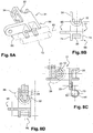
- FIGS. 8A, 8B, 8C and 8D show the different views of a first embodiment of such a holding means 31 or clipper module.
- This module has a substantially L-shaped section. One end of this L comprises a concave open surface 32 intended to snap onto the ramp. By pressing said concave surface against the wall of the ramp, the edges of the concave surface 32 move slightly apart, until the concave surface comes to bear against the wall of the ramp, and then the concave surface closes on the ramp.
- the module 31 is then assembled on the ramp.
- the second attachment lug 65 of the clipper module as shown in FIG. Figure 8C is in the form of a fastener having a shape substantially circular pierced with a hole 33.
- a collar 44 is fixed with a bolt on this bracket. This collar is intended to receive the elongate object 13 and to keep it inside the collar.
- This module also comprises a second fixing lug 66 in the form of a yoke having an axis 35 connecting two branches 74.
- the two branches 74 have a notched portion for receiving a portion of the elongate object.
- This notched portion has a substantially cylindrical hollow shape to fit the outer surface of the object to be received.
- a clamping collar attaches the elongate object to the axis 35.
- the main axis 53 of the elongate object 13 is then substantially parallel to the axis 35.
- the Figure 8C illustrates a particular example in which the module 31 is fixed on a ramp 23, the ramp being itself fixed on the lateral surface of the flange 22.
- the elongate object 13 is attached to the module by passing a collar 44 through the hole 33, the main axis 53 of this object is oriented transversely relative to the plane of the flanges.
- the figure 8D illustrates another example in which the module 31 is fixed on a ramp 24, the ramp being fixed on the curved edge 21 b of the flange 21.
- the axis 53 of the elongate object is substantially parallel to the plane of the flanges.
- FIGS 9A, 9B, 9C and 9D show the different views of another embodiment of the holding means 37.
- this form differs from the previous one in that the second fixing lug forms a ball joint 67 for orienting the elongate object in the chosen direction.
- this second fixing lug comprises a substantially circular piece 38 provided at its center with a projection 40 having a substantially spherical surface. This projection 40 cooperates with a spherical concave surface of a movable fixing element 43 so as to define a ball joint to orient the elongated object in the chosen direction.
- holes 41 are provided on the periphery of said piece 38 and the movable member to pass a means of 36.
- the elongate object 13 is fixed on the fastening element 43 via a cradle 68 having a portion conforming to the external shape of the element 43 and another indented part conforming to the external shape of the elongate object at to receive.
- This indented portion has a recess open at its ends, which is intended to receive at least a portion of a clamp.
- the circular piece 38 also has holes 33 for fixing a clamp 44 by means of a bolt.
- the fixing means for fixing the elongate object may be similar to those described in the first embodiment of the clipper module 31.
- the figures 10 and 11 represent an alternative embodiment of the flanges in a particular configuration of the structure 12 in which at least one of the bearing surfaces of the structure 12 forms two support surfaces at right angles 12a, 12c.
- the figure 10 shows a structure such as a frame having an L-shaped section.
- One of the two surfaces is formed of two bearing surfaces 12a, 12c at right angles.
- the flange 21 disposed on the side of this bearing surface then has two faces 21a, 21c interconnected by a connecting arm 48.
- This arm is configured so that the two surfaces 21a, 21c bear respectively respectively against the two square bearing surfaces 12a, 12c.
- the bearing face 21c also has an L-shaped section that bears against the bearing surface 12c and the lateral edge of the frame 12.
- the second flange 22 has a shape similar to that described in FIG. illustrated example on Figures 6A and 6B .
- the two flanges, once assembled together form an angle.
- the elongate objects 13 held on such a support are orthogonal to each other.
- the elongate objects 13 are held on the support by holding means or clipper module 31 which are illustrated on the Figures 8A-8D .
- one end of the flanges has a hole for receiving a clamping means 10 which also passes through a hole of the structure.
- the other ends are also assembled together by a similar clamping means.
- the figure 11 illustrates a frame having a T-shaped section.
- Each of the bearing surfaces 12a, 12b is formed of two angled bearing surfaces.
- the two flanges 21, 22 to form the fixing support each comprise two faces 21a, 21c interconnected by a connecting arm 48. Once assembled together, the two flanges form an angle so that the bearing surfaces 21c, 22c surround the base of the T-frame.
- the ramps 23, 24 are respectively secured to the side wall of these puddles. It is also possible that one of the two ramps 24 'is secured to the curved edge of one of the two flanges as shown in FIG. figure 12 .
- the figures 13 and 14 illustrate a third particularly advantageous form of the clipper module 69 used in the support according to the second embodiment.
- the figure 13 shows two supports mounted vis-a-vis in the opening 15 of the structure 12.
- a set of two intermediate support parts 70, 71 is disposed in the opening between the two supports, the main axis of this assembly being oriented parallel to one of the axes 75 of the structure.
- the ends of these two support pieces 70, 71 are fixed on the ramps 24 of the two supports facing each other via a clipper module 69.
- the two parts 70, 71 are slidably mounted relative to each other to adjust the length of the assembly as a function of the size of the opening. Moreover, this telescopic arrangement can make it possible to absorb the relative movements of the structures along which said parts 70, 71 extend, relative to one another. A section view of these two pieces is shown on the figure 14C .
- This set of intermediate telescopic support pieces 70, 71 advantageously allows to maintain in position several elongate objects 13 spaced apart by a distance by means of a cradle 68. It is very easy to adjust this distance by simply moving the cradle 68 .
- the figure 14A shows in more detail one of the two clipper modules 69 on which is fixed one end of the set of intermediate support pieces 70; 71. More specifically, the clipper module 69 comprises a first attachment lug 32 adapted to snap onto the ramp 24 of the support as in the other two embodiments of the modules to be clipped and a second bracket 72 on which is fixed an end of the assembly 70, 71.
- a section of the module 69 along the axis BB at the level of the second fastening tab 72 is represented on the Figure 14B .
- This second fastening lug 72 is provided with three fixing holes 73.
- the end of the intermediate piece 71 is in the form of a yoke comprising two branches 74.
- a known fastening means, such as a screw nut fastener or pin 75 connects the second bracket 72 to the branches 74. Holes in the second bracket and in the branches allow passage of the pin or screw.
- the other end of the assembly 70, 71 not shown on the Figure 14B is similarly fixed on the clipper module 69 of the second support.
- the Figure 14B also shows an example of an intermediate support piece which comprises a female ramp 72 secured to a male ramp 71 which is one of the two intermediate support pieces.
- the ends of the male ramp are fixed to the second fastening tab of the clipper module 69 by the fixing means described above.
- the figure 14C showing a sectional view along the axis AA of this intermediate support piece 71 shows that the female ramp 72 is in the form of a cylinder of circular section.
- the cradle 68 intended to fix the elongated object on the ramp has a part adapted to snap on the ramp 72 and another part to receive a portion of the support of the elongate object. A clamp is attached to the assembly.
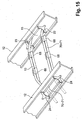
- the figure 15 illustrates the two forms of mounting of the supports as described in the Figures 14A and 14B 12
- the supports can be mounted vis-à-vis in the opening 15 of a crosspiece 12 to maintain in position the passage of an electric cable 13 for example through the opening ( Figure 13 ).
- the clipper modules 69 are mounted on the ramps 24 which are arranged on the curved edge of the two flanges so that the modules to be clipped are positioned vis-a-vis to receive the ends of the set of both.
- intermediate support parts 70, 71 The sliding of the part 70 in the part 71 makes it possible to adapt the length of the assembly 70 + 71 to the size of the opening 15.
- the figure 15 also shows a second form of assembly, the clipper modules 69 are mounted on ramps 23 which are arranged laterally relative to the flange so that the two clipper modules 69 are arranged vis-à-vis between two crosspieces 12.
- L assembly 70 + 71 is fixed on these two modules 69 between the two crosspieces 12.
- This second form of assembly said longitudinal assembly allows to maintain in position the passage of an electric cable 13 from one cross to the other by means of cradles 68 clipped on the female ramps 72.
- the sliding of the part 70 in the part 71 makes it possible to adjust in length as a function of the distance between the two crosspieces 12, and to absorb the relative movements of said sleepers 12.
Landscapes
- Engineering & Computer Science (AREA)
- Architecture (AREA)
- Civil Engineering (AREA)
- Structural Engineering (AREA)
- General Engineering & Computer Science (AREA)
- Mechanical Engineering (AREA)
- Clamps And Clips (AREA)
Claims (11)
- Träger (1) zum in Stellung halten eines länglichen Gegenstands (13) wie eines Stromkabels bezüglich einer Struktur (12), wobei der Träger aufweist:- zwei Verbindungsbauteile des Trägers mit der Struktur (2, 3, 2 1 , 22), die je eine Auflageseite (2a, 3a, 21a, 22a) haben, um auf jeder Seite der Struktur gegen eine Auflagefläche (12a, 12b) der Struktur in Auflage zu kommen, wobei die zwei Verbindungsbauteile durch Klemmeinrichtungen (7, 8, 10) zusammengebaut werden, wobei die zwei Verbindungsbauteile in Form eines Paars von Flanschen (21, 22) vorliegen, wobei die Flansche einen Rand mit einer im Wesentlichen gekrümmten Form (21b, 22b) und einen durch eine Erweiterung verlängerten Rand (25, 29) haben,- mindestens ein Trägerbauteil (4, 23, 24), das den länglichen Gegenstand (13) mittels Halteeinrichtungen (50, 31, 37, 69) halten kann,dadurch gekennzeichnet, dass das Trägerbauteil in Form einer Rampe (23, 24) vorliegt, die eine im Wesentlichen zylindrische Form hat und fest mit einem Verbindungsbauteil verbunden ist, und die Halteeinrichtungen die Form eines einklinkbaren Moduls (31, 37, 69) haben, das den länglichen Gegenstand (13) bezüglich der Rampe (23, 24) halten kann.
- Träger nach Anspruch 1, dadurch gekennzeichnet, dass die Auflageflächen (12a, 12b) der Struktur im Wesentlichen eben sind, wobei mindestens eine Öffnung (15) in der Struktur (12) ausgespart ist, um den länglichen Gegenstand (13) durchzulassen.
- Träger nach Anspruch 2, dadurch gekennzeichnet, dass die zwei Verbindungsbauteile (2, 3, 21, 22) so konfiguriert sind, dass sie den Umriss der Öffnung (15) zumindest teilweise einklemmen.
- Träger nach einem der Ansprüche 1 bis 3, dadurch gekennzeichnet, dass eines der zwei Verbindungsbauteile mindestens einen Vorsprung (7) und das andere Bauteil mindestens eine entsprechende Vertiefung (8) enthält, wobei die Vorsprünge und die entsprechenden Vertiefungen zusammenwirken, um die zwei Bauteile gegen die Auflageflächen der Struktur (12) zu blockieren.
- Träger nach einem der Ansprüche 1 bis 3, dadurch gekennzeichnet, dass die zwei Verbindungsbauteile Löcher (11) enthalten, die den Durchgang der Klemmeinrichtungen (10) erlauben, um die zwei Bauteile gegen die Auflageflächen der Struktur (12) zu blockieren.
- Träger nach einem der Ansprüche 1 bis 5, dadurch gekennzeichnet, dass das einklinkbare Modul (31, 37, 69) eine erste Befestigungslasche (32), die so konfiguriert ist, dass sie sich auf die Rampe (23, 24) einklinkt, und mindestens eine zweite Befestigungslasche (65, 66, 67, 72) aufweist, die dazu bestimmt ist, den länglichen Gegenstand (13) mittels Befestigungseinrichtungen (36, 44, 68) zu befestigen.
- Träger nach Anspruch 6, dadurch gekennzeichnet, dass die zweite Befestigungslasche (67) eine Kugelgelenkverbindung (40, 43) bildet, um den länglichen Gegenstand (13) in der gewählten Richtung auszurichten.
- Träger nach Anspruch 7, dadurch gekennzeichnet, dass die zweite Befestigungslasche ein Befestigungsbauteil (72) formt, das mindestens ein Loch (73) enthält.
- Träger nach Anspruch 8, dadurch gekennzeichnet, dass er eine Einheit von zwei Zwischenträgerbauteilen (70, 71) aufweist, die dazu bestimmt ist, zwischen zwei Befestigungsbauteile (72) eingefügt zu werden, die zu zwei verschiedenen Trägern gehören, wobei die zwei Bauteile (70, 71) zueinander gleitend montiert sind, um die Länge der Einheit einzustellen.
- Träger nach Anspruch 9, dadurch gekennzeichnet, dass das Zwischenträgerbauteil (70) eine Aufnahmerampe (72) enthält, die eine im Wesentlichen zylindrische Form mit kreisförmigem Querschnitt hat, wobei der längliche Gegenstand (13) bezüglich der Rampe durch Befestigungseinrichtungen (68) in Stellung gehalten wird.
- Träger nach einem der Ansprüche 1 bis 10, dadurch gekennzeichnet, dass, da mindestens eine der Auflageflächen (12a, 12b) der Struktur zwei winkelförmige Auflageflächen (12a, 12c) formt, der Flansch, der dazu bestimmt ist, gegen die winkelförmigen Auflageflächen (12a, 12c) in Auflage zu kommen, zwei Auflageseiten (21a, 21c) aufweist, die miteinander durch einen Verbindungsarm (48) verbunden sind, wobei der Arm so gestaltet ist, dass die zwei Auflageseiten (21a, 21c) je gegen die zwei winkelförmigen Auflageflächen (12a, 12c) in Auflage sind.
Applications Claiming Priority (2)
| Application Number | Priority Date | Filing Date | Title |
|---|---|---|---|
| FR0957903A FR2952418B1 (fr) | 2009-11-09 | 2009-11-09 | Support pour maintenir en position des objets allonges par rapport a une structure |
| PCT/FR2010/052398 WO2011055100A2 (fr) | 2009-11-09 | 2010-11-08 | Support pour maintenir en position des objets allongés par rapport à une structure |
Publications (2)
| Publication Number | Publication Date |
|---|---|
| EP2499712A2 EP2499712A2 (de) | 2012-09-19 |
| EP2499712B1 true EP2499712B1 (de) | 2016-06-22 |
Family
ID=42262440
Family Applications (1)
| Application Number | Title | Priority Date | Filing Date |
|---|---|---|---|
| EP10795424.0A Not-in-force EP2499712B1 (de) | 2009-11-09 | 2010-11-08 | Halter zum positionsfesten halten länglicher objekte relativ zu einer struktur |
Country Status (6)
| Country | Link |
|---|---|
| US (1) | US9209613B2 (de) |
| EP (1) | EP2499712B1 (de) |
| CA (1) | CA2779530A1 (de) |
| ES (1) | ES2587726T3 (de) |
| FR (1) | FR2952418B1 (de) |
| WO (1) | WO2011055100A2 (de) |
Families Citing this family (6)
| Publication number | Priority date | Publication date | Assignee | Title |
|---|---|---|---|---|
| US8622347B2 (en) | 2011-06-21 | 2014-01-07 | The Boeing Company | Clip attachment system connecting aircraft structures to each other |
| DE102011085793A1 (de) * | 2011-11-04 | 2013-05-08 | Airbus Operations Gmbh | Halterungsvorrichtung zum Haltern eines Kabels oder einer Leitung an einer Strukturkomponente eines Luft- oder Raumfahrzeugs sowie Luft- oder Raumfahrzeug |
| FR3019618B1 (fr) * | 2014-04-08 | 2016-11-04 | Airbus Operations Sas | Element de support pour au moins une conduite dans un aeronef, et dispositif de support correspondant |
| US9903510B2 (en) * | 2015-11-03 | 2018-02-27 | Commscope Technologies Llc | Hanger for mounting cables |
| AT518066B1 (de) * | 2016-06-29 | 2017-07-15 | Agru Kunststofftechnik Ges M B H | Verfahren zum Fügen von Rohrstücken sowie Zentriervorrichtung zum Fügen |
| US10969037B2 (en) | 2016-12-08 | 2021-04-06 | Hellermanntyton Corporation | Protective bundle routing grommet for wide range panel thickness |
Family Cites Families (10)
| Publication number | Priority date | Publication date | Assignee | Title |
|---|---|---|---|---|
| US3454247A (en) * | 1967-08-07 | 1969-07-08 | Thomas & Betts Corp | Bulkhead mounting plate |
| US4265005A (en) * | 1977-05-12 | 1981-05-05 | Heckethorn Manufacturing Company | U-Bolt clamp saddle construction |
| US5537714A (en) * | 1994-09-01 | 1996-07-23 | Erico International Corp. | Metal stud grommet |
| US5624089A (en) * | 1995-08-21 | 1997-04-29 | Ireco, Inc. | Pipe anchoring system |
| DE10010933C1 (de) | 2000-03-06 | 2001-08-16 | Daimler Chrysler Ag | Kabelhalter zur Befestigung von Kabeln in Fahrzeugstrukturen |
| US6595472B1 (en) * | 2001-12-28 | 2003-07-22 | Preformed Line Products Company | Cable clamp |
| CA2569874C (en) * | 2004-06-23 | 2013-02-12 | Physical Systems, Inc. | Adjustable mounting bracket |
| DE102005039652B4 (de) * | 2005-08-22 | 2011-07-21 | Airbus Operations GmbH, 21129 | Haltermodul zum Arretieren von Leitungen, Haltersystem zur geordneten Durchführung von Leitungen, Flugzeug und Verwendung einer Vielzahl von Haltermodulen |
| US7614593B2 (en) * | 2007-05-17 | 2009-11-10 | International Clamps, Inc. | Lined clamp for hoses and control lines |
| US20090072098A1 (en) | 2007-09-17 | 2009-03-19 | Inflight Investments Inc. | Support bracket for mounting wires to floor beams of an aircraft |
-
2009
- 2009-11-09 FR FR0957903A patent/FR2952418B1/fr not_active Expired - Fee Related
-
2010
- 2010-11-08 EP EP10795424.0A patent/EP2499712B1/de not_active Not-in-force
- 2010-11-08 WO PCT/FR2010/052398 patent/WO2011055100A2/fr active Application Filing
- 2010-11-08 US US13/508,556 patent/US9209613B2/en not_active Expired - Fee Related
- 2010-11-08 CA CA2779530A patent/CA2779530A1/fr not_active Abandoned
- 2010-11-08 ES ES10795424.0T patent/ES2587726T3/es active Active
Non-Patent Citations (1)
| Title |
|---|
| None * |
Also Published As
| Publication number | Publication date |
|---|---|
| EP2499712A2 (de) | 2012-09-19 |
| CA2779530A1 (fr) | 2011-05-12 |
| US9209613B2 (en) | 2015-12-08 |
| WO2011055100A2 (fr) | 2011-05-12 |
| ES2587726T3 (es) | 2016-10-26 |
| FR2952418B1 (fr) | 2012-01-20 |
| FR2952418A1 (fr) | 2011-05-13 |
| US20120292461A1 (en) | 2012-11-22 |
| WO2011055100A3 (fr) | 2012-04-05 |
Similar Documents
| Publication | Publication Date | Title |
|---|---|---|
| EP2499712B1 (de) | Halter zum positionsfesten halten länglicher objekte relativ zu einer struktur | |
| EP3553331B1 (de) | Verbindungsvorrichtung, die zwischen mindestens zwei teilen schwenkbar ist, luftfahrzeug, das eine abdeckung umfasst, die mit dieser schwenkbaren verbindungsvorrichtung ausgestattet ist | |
| WO2006123062A2 (fr) | Piece de liaison et ensemble de pieces de liaison orientables | |
| FR3033018A1 (fr) | Piece de support d'element tubulaire, notamment pour aeronef. | |
| WO2006097600A1 (fr) | Eclisse de raccordement pour chemin de câbles en fils | |
| EP3472479B1 (de) | Längenverstellbare pleuelstange für eine turbomaschine | |
| FR2943856A1 (fr) | Dispositif de support pour harnais electrique a la traversee d'une structure | |
| CA2660492A1 (fr) | Support pour fixer des cables electriques sur une structure | |
| FR3018960A1 (fr) | Element d'accouplement pour troncons de chemin de cables en treillis metallique, et troncon de chemin de cables en treillis metallique | |
| EP2648939B1 (de) | Leitung zur aufnahme von länglichen elementen, montageverfahren dafür und anordnung mit einer halterung und einer solchen leitung | |
| EP2518831B1 (de) | Anschlussmuffe für elektrische Kabel | |
| EP2505953A1 (de) | Positionier- und Befestigungsvorrichtung für balistisches Schutzgitter | |
| FR3038689A1 (fr) | Dispositif comprenant un berceau flexible | |
| EP2730487B1 (de) | Haltebauteil für zwei gegeneinander befestigte Karosserieelemente eines Kraftfahrzeugs | |
| EP0626533B1 (de) | Halteschelle auf einer Stütze für ein Rohr oder dergleichen | |
| EP3173645A1 (de) | Wälzlagerkäfig und wälzlager mit derartigem wälzlagerkäfig | |
| FR2911438A1 (fr) | Dispositif de suspension | |
| FR3093321A1 (fr) | Roue d’aéronef pourvue d’écrans thermiques | |
| FR2981877A1 (fr) | Dispositif d'accrochage d'une machine-outil portative | |
| WO2022089882A1 (fr) | Goulotte de passage de cable et assemblage d'une telle goulotte a un element structurel d'un vehicule automobile | |
| FR3126743A1 (fr) | Systeme de fixation d’une conduite a une cloison | |
| FR3077853A1 (fr) | Dispositif d'assemblage avec ecrou a embase et procede d'assemblage de plaques avec un tel dispositif | |
| CA2699492C (fr) | Dispositif de support pour harnais electrique a la traversee d'une structure | |
| WO2020249881A1 (fr) | Guide de montage pour une barre panhard de vehicule automobile | |
| FR3123407A1 (fr) | Ensemble de montage comprenant deux embouts maintenus emmanchés par une ceinture |
Legal Events
| Date | Code | Title | Description |
|---|---|---|---|
| PUAI | Public reference made under article 153(3) epc to a published international application that has entered the european phase |
Free format text: ORIGINAL CODE: 0009012 |
|
| 17P | Request for examination filed |
Effective date: 20120503 |
|
| AK | Designated contracting states |
Kind code of ref document: A2 Designated state(s): AL AT BE BG CH CY CZ DE DK EE ES FI FR GB GR HR HU IE IS IT LI LT LU LV MC MK MT NL NO PL PT RO RS SE SI SK SM TR |
|
| DAX | Request for extension of the european patent (deleted) | ||
| GRAP | Despatch of communication of intention to grant a patent |
Free format text: ORIGINAL CODE: EPIDOSNIGR1 |
|
| INTG | Intention to grant announced |
Effective date: 20160302 |
|
| GRAS | Grant fee paid |
Free format text: ORIGINAL CODE: EPIDOSNIGR3 |
|
| GRAA | (expected) grant |
Free format text: ORIGINAL CODE: 0009210 |
|
| AK | Designated contracting states |
Kind code of ref document: B1 Designated state(s): AL AT BE BG CH CY CZ DE DK EE ES FI FR GB GR HR HU IE IS IT LI LT LU LV MC MK MT NL NO PL PT RO RS SE SI SK SM TR |
|
| REG | Reference to a national code |
Ref country code: GB Ref legal event code: FG4D Free format text: NOT ENGLISH |
|
| REG | Reference to a national code |
Ref country code: CH Ref legal event code: EP |
|
| REG | Reference to a national code |
Ref country code: IE Ref legal event code: FG4D Free format text: LANGUAGE OF EP DOCUMENT: FRENCH |
|
| REG | Reference to a national code |
Ref country code: AT Ref legal event code: REF Ref document number: 808160 Country of ref document: AT Kind code of ref document: T Effective date: 20160715 |
|
| REG | Reference to a national code |
Ref country code: DE Ref legal event code: R096 Ref document number: 602010034196 Country of ref document: DE |
|
| REG | Reference to a national code |
Ref country code: LT Ref legal event code: MG4D |
|
| REG | Reference to a national code |
Ref country code: ES Ref legal event code: FG2A Ref document number: 2587726 Country of ref document: ES Kind code of ref document: T3 Effective date: 20161026 |
|
| REG | Reference to a national code |
Ref country code: NL Ref legal event code: MP Effective date: 20160622 |
|
| PG25 | Lapsed in a contracting state [announced via postgrant information from national office to epo] |
Ref country code: FI Free format text: LAPSE BECAUSE OF FAILURE TO SUBMIT A TRANSLATION OF THE DESCRIPTION OR TO PAY THE FEE WITHIN THE PRESCRIBED TIME-LIMIT Effective date: 20160622 Ref country code: LT Free format text: LAPSE BECAUSE OF FAILURE TO SUBMIT A TRANSLATION OF THE DESCRIPTION OR TO PAY THE FEE WITHIN THE PRESCRIBED TIME-LIMIT Effective date: 20160622 Ref country code: NO Free format text: LAPSE BECAUSE OF FAILURE TO SUBMIT A TRANSLATION OF THE DESCRIPTION OR TO PAY THE FEE WITHIN THE PRESCRIBED TIME-LIMIT Effective date: 20160922 |
|
| REG | Reference to a national code |
Ref country code: AT Ref legal event code: MK05 Ref document number: 808160 Country of ref document: AT Kind code of ref document: T Effective date: 20160622 |
|
| REG | Reference to a national code |
Ref country code: FR Ref legal event code: PLFP Year of fee payment: 7 |
|
| PG25 | Lapsed in a contracting state [announced via postgrant information from national office to epo] |
Ref country code: HR Free format text: LAPSE BECAUSE OF FAILURE TO SUBMIT A TRANSLATION OF THE DESCRIPTION OR TO PAY THE FEE WITHIN THE PRESCRIBED TIME-LIMIT Effective date: 20160622 Ref country code: SE Free format text: LAPSE BECAUSE OF FAILURE TO SUBMIT A TRANSLATION OF THE DESCRIPTION OR TO PAY THE FEE WITHIN THE PRESCRIBED TIME-LIMIT Effective date: 20160622 Ref country code: NL Free format text: LAPSE BECAUSE OF FAILURE TO SUBMIT A TRANSLATION OF THE DESCRIPTION OR TO PAY THE FEE WITHIN THE PRESCRIBED TIME-LIMIT Effective date: 20160622 Ref country code: GR Free format text: LAPSE BECAUSE OF FAILURE TO SUBMIT A TRANSLATION OF THE DESCRIPTION OR TO PAY THE FEE WITHIN THE PRESCRIBED TIME-LIMIT Effective date: 20160923 Ref country code: RS Free format text: LAPSE BECAUSE OF FAILURE TO SUBMIT A TRANSLATION OF THE DESCRIPTION OR TO PAY THE FEE WITHIN THE PRESCRIBED TIME-LIMIT Effective date: 20160622 Ref country code: LV Free format text: LAPSE BECAUSE OF FAILURE TO SUBMIT A TRANSLATION OF THE DESCRIPTION OR TO PAY THE FEE WITHIN THE PRESCRIBED TIME-LIMIT Effective date: 20160622 |
|
| PG25 | Lapsed in a contracting state [announced via postgrant information from national office to epo] |
Ref country code: RO Free format text: LAPSE BECAUSE OF FAILURE TO SUBMIT A TRANSLATION OF THE DESCRIPTION OR TO PAY THE FEE WITHIN THE PRESCRIBED TIME-LIMIT Effective date: 20160622 Ref country code: CZ Free format text: LAPSE BECAUSE OF FAILURE TO SUBMIT A TRANSLATION OF THE DESCRIPTION OR TO PAY THE FEE WITHIN THE PRESCRIBED TIME-LIMIT Effective date: 20160622 Ref country code: SK Free format text: LAPSE BECAUSE OF FAILURE TO SUBMIT A TRANSLATION OF THE DESCRIPTION OR TO PAY THE FEE WITHIN THE PRESCRIBED TIME-LIMIT Effective date: 20160622 Ref country code: EE Free format text: LAPSE BECAUSE OF FAILURE TO SUBMIT A TRANSLATION OF THE DESCRIPTION OR TO PAY THE FEE WITHIN THE PRESCRIBED TIME-LIMIT Effective date: 20160622 Ref country code: IS Free format text: LAPSE BECAUSE OF FAILURE TO SUBMIT A TRANSLATION OF THE DESCRIPTION OR TO PAY THE FEE WITHIN THE PRESCRIBED TIME-LIMIT Effective date: 20161022 |
|
| PGFP | Annual fee paid to national office [announced via postgrant information from national office to epo] |
Ref country code: DE Payment date: 20161121 Year of fee payment: 7 |
|
| PG25 | Lapsed in a contracting state [announced via postgrant information from national office to epo] |
Ref country code: PT Free format text: LAPSE BECAUSE OF FAILURE TO SUBMIT A TRANSLATION OF THE DESCRIPTION OR TO PAY THE FEE WITHIN THE PRESCRIBED TIME-LIMIT Effective date: 20161024 Ref country code: PL Free format text: LAPSE BECAUSE OF FAILURE TO SUBMIT A TRANSLATION OF THE DESCRIPTION OR TO PAY THE FEE WITHIN THE PRESCRIBED TIME-LIMIT Effective date: 20160622 Ref country code: BE Free format text: LAPSE BECAUSE OF NON-PAYMENT OF DUE FEES Effective date: 20161130 Ref country code: AT Free format text: LAPSE BECAUSE OF FAILURE TO SUBMIT A TRANSLATION OF THE DESCRIPTION OR TO PAY THE FEE WITHIN THE PRESCRIBED TIME-LIMIT Effective date: 20160622 Ref country code: SM Free format text: LAPSE BECAUSE OF FAILURE TO SUBMIT A TRANSLATION OF THE DESCRIPTION OR TO PAY THE FEE WITHIN THE PRESCRIBED TIME-LIMIT Effective date: 20160622 |
|
| REG | Reference to a national code |
Ref country code: DE Ref legal event code: R097 Ref document number: 602010034196 Country of ref document: DE |
|
| PLBE | No opposition filed within time limit |
Free format text: ORIGINAL CODE: 0009261 |
|
| STAA | Information on the status of an ep patent application or granted ep patent |
Free format text: STATUS: NO OPPOSITION FILED WITHIN TIME LIMIT |
|
| 26N | No opposition filed |
Effective date: 20170323 |
|
| PG25 | Lapsed in a contracting state [announced via postgrant information from national office to epo] |
Ref country code: DK Free format text: LAPSE BECAUSE OF FAILURE TO SUBMIT A TRANSLATION OF THE DESCRIPTION OR TO PAY THE FEE WITHIN THE PRESCRIBED TIME-LIMIT Effective date: 20160622 |
|
| REG | Reference to a national code |
Ref country code: CH Ref legal event code: PL |
|
| PG25 | Lapsed in a contracting state [announced via postgrant information from national office to epo] |
Ref country code: CH Free format text: LAPSE BECAUSE OF NON-PAYMENT OF DUE FEES Effective date: 20161130 Ref country code: LI Free format text: LAPSE BECAUSE OF NON-PAYMENT OF DUE FEES Effective date: 20161130 |
|
| REG | Reference to a national code |
Ref country code: IE Ref legal event code: MM4A |
|
| PG25 | Lapsed in a contracting state [announced via postgrant information from national office to epo] |
Ref country code: SI Free format text: LAPSE BECAUSE OF FAILURE TO SUBMIT A TRANSLATION OF THE DESCRIPTION OR TO PAY THE FEE WITHIN THE PRESCRIBED TIME-LIMIT Effective date: 20160622 |
|
| PG25 | Lapsed in a contracting state [announced via postgrant information from national office to epo] |
Ref country code: LU Free format text: LAPSE BECAUSE OF NON-PAYMENT OF DUE FEES Effective date: 20161130 |
|
| REG | Reference to a national code |
Ref country code: FR Ref legal event code: PLFP Year of fee payment: 8 |
|
| PG25 | Lapsed in a contracting state [announced via postgrant information from national office to epo] |
Ref country code: IE Free format text: LAPSE BECAUSE OF NON-PAYMENT OF DUE FEES Effective date: 20161108 |
|
| REG | Reference to a national code |
Ref country code: BE Ref legal event code: MM Effective date: 20161130 |
|
| PG25 | Lapsed in a contracting state [announced via postgrant information from national office to epo] |
Ref country code: CY Free format text: LAPSE BECAUSE OF FAILURE TO SUBMIT A TRANSLATION OF THE DESCRIPTION OR TO PAY THE FEE WITHIN THE PRESCRIBED TIME-LIMIT Effective date: 20160622 Ref country code: HU Free format text: LAPSE BECAUSE OF FAILURE TO SUBMIT A TRANSLATION OF THE DESCRIPTION OR TO PAY THE FEE WITHIN THE PRESCRIBED TIME-LIMIT; INVALID AB INITIO Effective date: 20101108 |
|
| REG | Reference to a national code |
Ref country code: DE Ref legal event code: R119 Ref document number: 602010034196 Country of ref document: DE |
|
| PG25 | Lapsed in a contracting state [announced via postgrant information from national office to epo] |
Ref country code: TR Free format text: LAPSE BECAUSE OF FAILURE TO SUBMIT A TRANSLATION OF THE DESCRIPTION OR TO PAY THE FEE WITHIN THE PRESCRIBED TIME-LIMIT Effective date: 20160622 Ref country code: MC Free format text: LAPSE BECAUSE OF FAILURE TO SUBMIT A TRANSLATION OF THE DESCRIPTION OR TO PAY THE FEE WITHIN THE PRESCRIBED TIME-LIMIT Effective date: 20160622 Ref country code: MK Free format text: LAPSE BECAUSE OF FAILURE TO SUBMIT A TRANSLATION OF THE DESCRIPTION OR TO PAY THE FEE WITHIN THE PRESCRIBED TIME-LIMIT Effective date: 20160622 |
|
| PG25 | Lapsed in a contracting state [announced via postgrant information from national office to epo] |
Ref country code: BG Free format text: LAPSE BECAUSE OF FAILURE TO SUBMIT A TRANSLATION OF THE DESCRIPTION OR TO PAY THE FEE WITHIN THE PRESCRIBED TIME-LIMIT Effective date: 20160622 |
|
| PG25 | Lapsed in a contracting state [announced via postgrant information from national office to epo] |
Ref country code: MT Free format text: LAPSE BECAUSE OF FAILURE TO SUBMIT A TRANSLATION OF THE DESCRIPTION OR TO PAY THE FEE WITHIN THE PRESCRIBED TIME-LIMIT Effective date: 20160622 |
|
| PG25 | Lapsed in a contracting state [announced via postgrant information from national office to epo] |
Ref country code: DE Free format text: LAPSE BECAUSE OF NON-PAYMENT OF DUE FEES Effective date: 20180602 Ref country code: AL Free format text: LAPSE BECAUSE OF FAILURE TO SUBMIT A TRANSLATION OF THE DESCRIPTION OR TO PAY THE FEE WITHIN THE PRESCRIBED TIME-LIMIT Effective date: 20160622 |
|
| PGFP | Annual fee paid to national office [announced via postgrant information from national office to epo] |
Ref country code: IT Payment date: 20191128 Year of fee payment: 10 Ref country code: FR Payment date: 20191120 Year of fee payment: 10 Ref country code: ES Payment date: 20191220 Year of fee payment: 10 |
|
| PGFP | Annual fee paid to national office [announced via postgrant information from national office to epo] |
Ref country code: GB Payment date: 20191120 Year of fee payment: 10 |
|
| GBPC | Gb: european patent ceased through non-payment of renewal fee |
Effective date: 20201108 |
|
| PG25 | Lapsed in a contracting state [announced via postgrant information from national office to epo] |
Ref country code: FR Free format text: LAPSE BECAUSE OF NON-PAYMENT OF DUE FEES Effective date: 20201130 Ref country code: IT Free format text: LAPSE BECAUSE OF NON-PAYMENT OF DUE FEES Effective date: 20201108 |
|
| PG25 | Lapsed in a contracting state [announced via postgrant information from national office to epo] |
Ref country code: GB Free format text: LAPSE BECAUSE OF NON-PAYMENT OF DUE FEES Effective date: 20201108 |
|
| REG | Reference to a national code |
Ref country code: ES Ref legal event code: FD2A Effective date: 20220201 |
|
| PG25 | Lapsed in a contracting state [announced via postgrant information from national office to epo] |
Ref country code: ES Free format text: LAPSE BECAUSE OF NON-PAYMENT OF DUE FEES Effective date: 20201109 |