EP2499511B1 - Method for measuring the angles of multiple paths by means of a two-way receiver - Google Patents
Method for measuring the angles of multiple paths by means of a two-way receiver Download PDFInfo
- Publication number
- EP2499511B1 EP2499511B1 EP10773932.8A EP10773932A EP2499511B1 EP 2499511 B1 EP2499511 B1 EP 2499511B1 EP 10773932 A EP10773932 A EP 10773932A EP 2499511 B1 EP2499511 B1 EP 2499511B1
- Authority
- EP
- European Patent Office
- Prior art keywords
- matrix
- signal
- symbols
- estimated
- paths
- Prior art date
- Legal status (The legal status is an assumption and is not a legal conclusion. Google has not performed a legal analysis and makes no representation as to the accuracy of the status listed.)
- Not-in-force
Links
Images


Classifications
-
- H—ELECTRICITY
- H04—ELECTRIC COMMUNICATION TECHNIQUE
- H04L—TRANSMISSION OF DIGITAL INFORMATION, e.g. TELEGRAPHIC COMMUNICATION
- H04L25/00—Baseband systems
- H04L25/02—Details ; arrangements for supplying electrical power along data transmission lines
- H04L25/0202—Channel estimation
- H04L25/0204—Channel estimation of multiple channels
-
- G—PHYSICS
- G01—MEASURING; TESTING
- G01S—RADIO DIRECTION-FINDING; RADIO NAVIGATION; DETERMINING DISTANCE OR VELOCITY BY USE OF RADIO WAVES; LOCATING OR PRESENCE-DETECTING BY USE OF THE REFLECTION OR RERADIATION OF RADIO WAVES; ANALOGOUS ARRANGEMENTS USING OTHER WAVES
- G01S3/00—Direction-finders for determining the direction from which infrasonic, sonic, ultrasonic, or electromagnetic waves, or particle emission, not having a directional significance, are being received
- G01S3/02—Direction-finders for determining the direction from which infrasonic, sonic, ultrasonic, or electromagnetic waves, or particle emission, not having a directional significance, are being received using radio waves
- G01S3/14—Systems for determining direction or deviation from predetermined direction
- G01S3/46—Systems for determining direction or deviation from predetermined direction using antennas spaced apart and measuring phase or time difference between signals therefrom, i.e. path-difference systems
- G01S3/50—Systems for determining direction or deviation from predetermined direction using antennas spaced apart and measuring phase or time difference between signals therefrom, i.e. path-difference systems the waves arriving at the antennas being pulse modulated and the time difference of their arrival being measured
-
- G—PHYSICS
- G01—MEASURING; TESTING
- G01S—RADIO DIRECTION-FINDING; RADIO NAVIGATION; DETERMINING DISTANCE OR VELOCITY BY USE OF RADIO WAVES; LOCATING OR PRESENCE-DETECTING BY USE OF THE REFLECTION OR RERADIATION OF RADIO WAVES; ANALOGOUS ARRANGEMENTS USING OTHER WAVES
- G01S3/00—Direction-finders for determining the direction from which infrasonic, sonic, ultrasonic, or electromagnetic waves, or particle emission, not having a directional significance, are being received
- G01S3/02—Direction-finders for determining the direction from which infrasonic, sonic, ultrasonic, or electromagnetic waves, or particle emission, not having a directional significance, are being received using radio waves
- G01S3/74—Multi-channel systems specially adapted for direction-finding, i.e. having a single antenna system capable of giving simultaneous indications of the directions of different signals
-
- H—ELECTRICITY
- H04—ELECTRIC COMMUNICATION TECHNIQUE
- H04L—TRANSMISSION OF DIGITAL INFORMATION, e.g. TELEGRAPHIC COMMUNICATION
- H04L25/00—Baseband systems
- H04L25/02—Details ; arrangements for supplying electrical power along data transmission lines
- H04L25/0202—Channel estimation
- H04L25/024—Channel estimation channel estimation algorithms
- H04L25/0242—Channel estimation channel estimation algorithms using matrix methods
Definitions
- the object of the invention relates to a method and a system for finding the arrival direction of several source signals Ei in a network comprising N sensors or reception antennas, with at least two reception channels, one of the antennas of the network. being continuously to a receiver 3 1 connected via a two-way switch, the other N-1 antennas receiving the signal only when connected through the switch two channels to a second receiver 3 2.
- the switch has a switching duration T and a switching time ⁇ T.
- the letter p denotes the index of a path and M the number of paths.
- the technical field in which the subject of the present invention applies relates to the processing of antennas which processes the signals of several emitting sources from a multi-sensor reception system.
- the sensors are antennas and the radio sources propagate with a polarization dependent on the transmitting antenna.
- the sensors are microphones (or hydrophones) and the sources are sound.
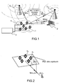
- the figure 1 shows an example of an antenna processing system which is composed of a network 1 of sensors or antennas 4i receiving signals from different sources with different arrival angles ⁇ p or ⁇ m and a receiver 3 , the figure also shows the obstacles 2 on which the signals are reflected.
- the field is more particularly that of the direction finding which consists in estimating the angles of arrival or incidences of the sources Ei (DOA for Direction Of Arrival in Anglo-Saxon).
- the elementary sensors or antennas 4i of the network which receive the signals emitted by the sources with a phase and an amplitude depending in particular on their angles of incidence and the position of the sensors.
- the angles of incidence are parameterized in a dimension 1 D by the azimuth angle ⁇ p or ⁇ m and in two dimensions 2D by the azimuth ⁇ p or ⁇ m and the elevation ⁇ p or ⁇ m .
- a 1 D direction finding is defined by techniques that estimate only the azimuth by assuming that the waves of the sources propagate in the plane of the sensor array.
- One of the objectives of antenna processing techniques is primarily to exploit the spatial diversity generated by the multi-antenna reception of incident signals by using the spatial position of network antennas to better exploit divergence in incidence and frequency. distance from sources.
- the technical field in which the object of the present patent application lies is that of direction finding in the presence of multipath resulting from the presence of obstacles placed in the path of the signals emitted by the source as illustrated in FIG. figure 3 .
- the m-th source E m propagates along paths P of incidence ⁇ mp (1 ⁇ p ⁇ M) that are caused by M-1 obstacles in the radio environment.
- One of the problems to be solved is that of multi-path direction finding of a transmitter emitting a signal which comprises at least one reference signal TSC or d (t) within a received message and which uses the knowledge of the Message formatting filter, as part of a two-way type reception system.
- the reception system is said to be two-way because it comprises two receivers 3 1 and 3 2 , which are switched alternately and periodically on a pair of antennas 4i, 4j of the sensor array as will be described in the description which follows.
- Multipath goniometry requires the implementation of a high resolution method requiring a number of reception channels strictly greater than the number of paths. More particularly, the direction finding methods using a reference signal assume that the reference signal is detected simultaneously on all the sensors. With a two-way reception system, the reference signal TSC can be seen typically on a single couple of antennas of the sensor network. Indeed, the reference signal may have a duration less than the switching time T.
- the MUSIC algorithm exploits the properties of the covariance matrix of the signal in order to estimate parameters such as the effects of the sources.
- the switching system has the disadvantage of only giving access to part of the information of the covariance matrix.
- the method according to the invention therefore consists in adapting the direction finding algorithm so as not to use the covariance matrix according to the art. earlier, but to use a matrix of direction A whose columns correspond to vectors of direction or directional vectors of each of the paths, in order to separate the different paths.
- the construction of the covariance matrix is based in particular on the knowledge of the training sequences contained in the message and also on the knowledge of the formatting filter of the linear modulation.
- the formatting filter used will be that of the linearized version of the GMSK and the learning sequences will be those TSC (Training Sequence Code), TCH (Traffic Channel) or Random Access Channel (RACH) signals.
- the method according to the invention will contain a first synchronization step which uses the symbols of the reference sequences, then the received signal is demodulated around the sequence using the shaping filter of the modulation concerned (GSM, UMTS, etc. ).
- the method may comprise an estimation step based on the estimated values of the coefficients ⁇ n and then a step where an MMSE method is applied which consists in minimizing the Euclidean distance between ⁇ n and the states ⁇ k of a constellation.
- an MMSE method is applied which consists in minimizing the Euclidean distance between ⁇ n and the states ⁇ k of a constellation.
- the method comprises a step in which one applies an algorithm MUSIC on the matrix (A . ⁇ . H) (A . ⁇ . H) H.
- linearly modulated signals which comprise a structure or a format such that includes a sequence on which a receiver can synchronize, and which is known expression of the shaping filter or filter used to modulate the symbols of the message.
- the radio-communication signals have, by their nature, reference signals in order, in particular, to build receivers or equalizers that cancel the effects of multipaths as well as those of interference. This is, for example, the case of GPS signals, radar signals that are generally composed of replicas to measure the propagation time between transmission and reception.
- FIG 5 is represented an exemplary system architecture comprising N sensors 4i in connection with a switch 10, itself connected to two receivers 3 1 , 3 2 .
- the first antenna 4 1 continuously receives a signal x 1 (t), the antenna is connected to the reference receiver 3 1.
- the signals x n (t) of the N-1 other antennas regularly commute to the second receiver 3 2, that is to say that the receiver R 2 will receive the signals received from the N-1 other antennas that are not the reference antenna.
- the signal transmitted s ( t ) by the transmitters of the switching system is in the example that of a linear modulation containing a reference signal d ( t ).
- A [ a ( ⁇ 1 ) ... a ( ⁇ M )] is the mixing matrix of the paths or sources that are also called "leading matrix”.
- the columns of this master matrix are the direction vectors of the paths.
- the multipath phenomenon is modeled in this example by specular multipaths.
- the signal emitted when it encounters an obstacle is reflected in one direction, unlike diffuse multipaths, reflected along a continuum of directions.
- Each path p is therefore associated with a single triplet ( ⁇ p , ⁇ p , ⁇ p ) respectively denoting the power, the propagation delay and the arrival angle for 1 ⁇ p ⁇ M , given that M is the number of paths.
- ⁇ at 1 ⁇ ... at NOT ⁇ T the response of the network of N antennas to a signal arriving at an angle ⁇ .
- Equation 3.1 is always checked at the antennas reception.
- the 2-way acquisition system continuously receives on the first receiver 3 1 the signal x 1 (t), while the second receiver 3 2 , because of the switching, will receive alternately the signals x 2 (t) at x N (t) for disjointed "t" time slots.
- the system makes it possible to correlate the signals x i (t) and x j (t) when i> 1 and j> 1.
- the system therefore has truncated signals and no longer all the signals received.
- An example of the signals received on the channels 1, .. i, ..N is represented at the figure 6 .
- the hatched portions correspond to the duration of reception of the signal on a given sensor.
- a ij ⁇ a ij ( ⁇ 1 ) ⁇ a ij ( ⁇ M ) ⁇ the sub-matrix of the matrix of direction A associated with the antennas i and j, since A ij contains the i th and j th lines of the matrix A.
- the switching time ⁇ t of the acquisition system will subsequently be considered zero.
- the idea implemented in the method and the system according to the invention ( figure 8 ) is to design a signal processing to reconstruct the direction matrix A (or a linearly dependent matrix of A ) to separate the M different paths.
- the method will then apply a direction finding algorithm, for example, the MUSIC type algorithm on each column of the above-mentioned direction matrix.
- the objective is to demodulate the linearly modulated signals around the reference sequence, knowing the shaping filter used during the modulation of the signal.
- This step requires knowing the position of the first modulated symbol of the sequence d (t) consisting of symbols dn in the signals received on the antennas 4 1 , ..., 4 N.
- a so-called symbol synchronization step is used here.
- the GMSK modulation can then be seen as a QPSK modulated linearly by the filter C 0 ( t ).
- TSC sequences of GSM K 26.
- the steps of the algorithm will first consist in performing symbol synchronization on the reference antenna 4 1 and then in estimating the matrix of passage between the signal x 1 ( nT s ) and the symbols c n . This will make it possible to build front and back filters which will make it possible to estimate and detect by the quadratic method, for example MMSE, the symbols on either side of the learning sequence.
- the symbols c n are estimated 21, it will be possible to estimate the channel matrix A i . ⁇ . H. , 22, on each of the commutations then to build the matrix of channel A . ⁇ . H. It will then be possible to estimate the 23 ⁇ p delays 1 ⁇ p ⁇ M from the matrix (A . ⁇ . H.) H (Ai . ⁇ .
- a more direct method of goniometry paths comprises applying a MUSIC type algorithm to the matrix (A . ⁇ . H.) (A . ⁇ . H.) H .From estimation values A i . ⁇ . H., It will also be possible to estimate the values of the angles ⁇ p from the matrix (A . ⁇ . H). H (A i . ⁇ . H.) H for i ⁇ p ⁇ M, 26.
- the synchronization criterion gives a peak that goes up to 1. This means that the hypothesis made on the length of the channel is just and that symbol synchronization works. From a practical point of view, the spreading of the channel depends, on the one hand, on the temporal spread T of the shaping filter C 0 ( t ) and on the other hand on the spreading of the channel characterized by the delays. multipaths.
- 1
- a i . ⁇ . H is the i-th line of A . ⁇ . H.
- the matrix A i . ⁇ . H is, for example, obtained in the least squares sense by minimizing the difference between x i ( nT s ) and c n AT i . ⁇ .
- a second approach for the multi-path direction finding is to separate the paths after their delay and then to goniometer them independently.
- the detection of the rank of R HH by a method known to those skilled in the art allows to know the number M of paths and deduce the projector noise ⁇ ( R HH ) of the MUSIC algorithm.
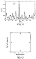
- the second approach has the advantage of being more robust to antenna calibration errors because each path is goniometrically independent, as shown in FIG. figure 12 , where the incidences of the two paths are 40 ° and 80 °.
- the method requires a good estimate of the delays ⁇ p .
Description
L'objet de l'invention concerne un procédé et un système permettant de trouver la Direction d'arrivée de plusieurs signaux sources Ei dans un réseau comprenant N capteurs ou antennes de réception, avec au moins deux voies de réception, une des antennes du réseau étant reliée de manière continue à un récepteur 31, via un commutateur bi-voies, les autres N-1 antennes recevant le signal uniquement lorsqu'elles sont reliées par l'intermédiaire du commutateur deux voies à un deuxième récepteur 32. Le commutateur a une durée de commutation T et un temps de commutation δT.The object of the invention relates to a method and a system for finding the arrival direction of several source signals Ei in a network comprising N sensors or reception antennas, with at least two reception channels, one of the antennas of the network. being continuously to a
Dans la suite de la description, la lettre p désigne l'indice d'un trajet et M le nombre de trajets.In the remainder of the description, the letter p denotes the index of a path and M the number of paths.
Le domaine technique dans lequel l'objet de la présente invention s'applique, concerne le traitement d'antennes qui traite les signaux de plusieurs sources émettrices à partir d'un système de réception multi-capteurs. Dans un contexte électromagnétique, les capteurs sont des antennes et les sources radioélectriques se propagent avec une polarisation dépendante de l'antenne d'émission. Dans un contexte acoustique, les capteurs sont des microphones (ou hydrophones) et les sources sont sonores. La
L'un des objectifs des techniques de traitement d'antennes est principalement d'exploiter la diversité spatiale générée par la réception multi-antennes des signaux incidents qui consiste à utiliser la position spatiale des antennes du réseau pour mieux exploiter les divergences en incidence et en distance des sources.One of the objectives of antenna processing techniques is primarily to exploit the spatial diversity generated by the multi-antenna reception of incident signals by using the spatial position of network antennas to better exploit divergence in incidence and frequency. distance from sources.
Le domaine technique dans lequel se situe l'objet de la présente demande de brevet est celui de la goniométrie en présence de multi trajets résultant de la présence d'obstacles placés sur le trajet des signaux émis par la source comme il est illustré à la
L'un des problèmes à résoudre est celui de la goniométrie des multi-trajets d'un émetteur émettant un signal qui comporte au moins un signal de référence TSC ou d(t) au sein d'un message reçu et qui utilise la connaissance du filtre de la mise en forme du message, dans le cadre d'un système de réception de type bi-voies. Le système de réception est dit bi-voies, car il comporte deux récepteurs 31 et 32, qui sont commutés alternativement et périodiquement sur un couple d'antennes 4i, 4j du réseau de capteurs comme il sera décrit dans la description qui suit. La goniométrie de multi-trajets nécessite la mise en oeuvre d'un procédé haute résolution nécessitant un nombre de voies de réception strictement supérieur au nombre de trajets. Plus particulièrement, les méthodes de goniométrie utilisant un signal de référence supposent que le signal de référence soit détecté simultanément sur tous les capteurs. Avec un système de réception bi-voies, le signal de référence TSC peut être vu typiquement sur un seul couple d'antennes du réseau de capteurs. En effet, le signal de référence peut avoir une durée inférieure au temps de commutation T.One of the problems to be solved is that of multi-path direction finding of a transmitter emitting a signal which comprises at least one reference signal TSC or d (t) within a received message and which uses the knowledge of the Message formatting filter, as part of a two-way type reception system. The reception system is said to be two-way because it comprises two
Il est connu de l'art antérieur, des méthodes de goniométrie 2 voies. Par exemple, le brevet du Demandeur
- Une première alternative applicable dans le cas général, plusieurs sources et plusieurs trajets, nécessite un algorithme coûteux en temps de calcul tel que le maximum de vraisemblance, méthode connue de l'Homme du métier,
- Une deuxième alternative dont le coût de calcul est équivalent à celui de l'algorithme MUSIC connu des spécialistes du traitement de signal, nécessite l'existence de sources (trajet d'un émetteur) ayant des spectres différents. Cette alternative ne peut être appliquée en présence de multi-trajets ou dans un réseau de radio-communication tel que le GSM où tous les mobiles ont le même spectre.
- A first alternative applicable in the general case, several sources and several paths, requires an expensive algorithm in computing time such as maximum likelihood, a method known to those skilled in the art,
- A second alternative whose calculation cost is equivalent to that of the MUSIC algorithm known to signal processing specialists, requires the existence of sources (path of an emitter) having different spectra. This alternative can not be applied in the presence of multipath or in a radio communication network such as GSM where all mobiles have the same spectrum.
Il est aussi connu des méthodes de goniométrie à référence par exemple dans les brevets
Du point de vue du Demandeur, les méthodes décrites dans les références précitées et connues de l'art antérieur, permettent une résolution partielle du problème technique posé. Les méthodes de goniométrie Haute Résolution avec un système de réception bi-voies envisagées dans le brevet
L'algorithme MUSIC exploite les propriétés de la matrice de covariance du signal afin d'estimer des paramètres tels que les incidences des sources. Or le système de commutation présente l'inconvénient de ne donner accès qu'à une partie des informations de la matrice de covariance.The MUSIC algorithm exploits the properties of the covariance matrix of the signal in order to estimate parameters such as the effects of the sources. However, the switching system has the disadvantage of only giving access to part of the information of the covariance matrix.
En effet, dans le cas multivoies, il est possible d'estimer les N2 éléments r xixj de la matrice de covariance R xx qui s'écrit : 
Le procédé selon l'invention consiste donc à adapter l'algorithme de goniométrie afin de ne pas utiliser la matrice de covariance selon l'art antérieur, mais d'utiliser une matrice de direction A dont les colonnes correspondent à des vecteurs de direction ou vecteurs directeurs de chacun des trajets, afin de séparer les différents trajets. La construction de la matrice de covariance s'appuie notamment sur la connaissance des séquences d'apprentissage contenues dans le message et aussi sur la connaissance du filtre de mise en forme de la modulation linéaire. Dans le cas du GSM (Global System Mobile) où la modulation est une modulation de type GMSK (Gaussian Minimum Shift Keying), le filtre de mise en forme utilisé sera celui de la version linéarisé de la GMSK et les séquences d'apprentissage seront celles des signaux TSC (abrégé anglo-saxon de Training Sequence Code), TCH (Traffic Channel) ou RACH (Random Access Channel). Le procédé selon l'invention va contenir une première étape de synchronisation qui utilise les symboles des séquences de référence, puis le signal reçu est démodulé autour de la séquence en utilisant le filtre de mise en forme de la modulation concernée (GSM, UMTS, etc ...).The method according to the invention therefore consists in adapting the direction finding algorithm so as not to use the covariance matrix according to the art. earlier, but to use a matrix of direction A whose columns correspond to vectors of direction or directional vectors of each of the paths, in order to separate the different paths. The construction of the covariance matrix is based in particular on the knowledge of the training sequences contained in the message and also on the knowledge of the formatting filter of the linear modulation. In the case of the GSM (Global System Mobile) where the modulation is a Gaussian Minimum Shift Keying (GMSK) type modulation, the formatting filter used will be that of the linearized version of the GMSK and the learning sequences will be those TSC (Training Sequence Code), TCH (Traffic Channel) or Random Access Channel (RACH) signals. The method according to the invention will contain a first synchronization step which uses the symbols of the reference sequences, then the received signal is demodulated around the sequence using the shaping filter of the modulation concerned (GSM, UMTS, etc. ...).
L'invention concerne un procédé pour déterminer les angles d'arrivée ou la Direction d'Arrivée des multi-trajets associés à un émetteur ou source Ei dans un système comportant N antennes de réception, une desdites antennes étant une antenne de référence reliée en continu à un premier récepteur et les N-1 autres antennes étant reliées à un deuxième récepteur, de manière discontinue grâce à un commutateur bivoies, ladite antenne de référence recevant un signal x1(t) en continu, ledit signal comprenant une séquence de référence d(t), caractérisé en ce qu'il comporte au moins les étapes suivantes :
- effectuer une synchronisation symbole sur l'antenne de référence puis estimer la matrice de passage entre le signal x 1 (nTs ) reçu sur ladite antenne de référence et les symboles cn, où Ts est le temps symbole,
- construire deux filtres qui permettront d'estimer et de détecter les symboles de part et d'autre de la séquence de référence d(t) constituées des symboles dn,
- estimer la matrice de canal A 1i .Ω.H. sur chacune des
commutations 1 à N à partir de la connaissance des symboles cn estimés et des signaux x 1(nTs ), et construire la matrice de canal A.Ω.H. où H est la matrice de canal définie par
- estimer la valeur de l'angle θp à partir de la matrice de canal A.Ω.H. sachant que


- performing a symbol synchronization on the reference antenna and then estimating the matrix of passage between the signal x 1 ( nT s ) received on said reference antenna and the symbols c n , where T s is the symbol time,
- construct two filters that will make it possible to estimate and detect the symbols on either side of the reference sequence d (t) consisting of the symbols d n ,
- estimate the channel matrix A 1 i . Ω.H. on each of the
commutations 1 to N from the knowledge of the estimated symbols c n and the signals x 1 ( nT s ), and construct the channel matrix A .Ω. H. where H is the channel matrix defined by - estimate the value of the angle θ p from the channel matrix A Ω. H. knowing that
L'étape de synchronisation symbole est, par exemple, exécutée de la manière suivante :
- en considérant le signal reçu sur l'antenne de référence (41) x 1((n+i)Ts ) = A 1.Ω.H.d n + b 1((n + i)Ts ) pour 1 ≤ n ≤ K
- où K est le nombre de symboles de la séquence de référence, où A 1 est la première ligne de la matrice A, chercher l'indice i qui minimise l'écart entre x 1((n + i)Ts ) signal reçu sur l'antenne (41) et A 1.Ω.H.d n tel que

- considering the signal received on the reference antenna (4 1 ) x 1 (( n + 1 ) T s ) = A 1 .Ω. Hd n + b 1 (( n + i ) T s ) for 1 ≤ n ≤ K
- where K is the number of symbols of the reference sequence, where A 1 is the first row of the matrix A, look for the index i which minimizes the difference between x 1 (( n + i ) T s ) received on the antenna (4 1 ) and A 1 .Ω. Hd n such that
Le procédé peut comporter une étape d'estimation à partir des valeurs estimées des coefficients ĉn , puis une étape où l'on applique une méthode MMSE qui consiste à minimiser la distance euclidienne entre ĉn et les états η k d'une constellation.
Dans le cas de la GMSK qui est à 4 états comme la QPSK alors η1 = 1, η2 = -1, η3 = j et η4 = -j, le symbole démodulé est alors ![]()
In the case of GMSK which has 4 states like QPSK then η 1 = 1, η 2 = -1, η 3 = j and η 4 = - j , the demodulated symbol is then ![]()
Dans le cas de la GMSK où le module des symboles vérifie |cn | = 1, le procédé comprend une étape d'amélioration du calcul MMSE en effectuant ![]()
![]()
Selon une variante de réalisation, la matrice de canal complète A.Ω.H est estimée à partir des symboles {cn} et des observations commutées qui vérifie 
La matrice A i .Ω.H est, par exemple, obtenue au sens des moindres carrés en minimisant l'écart entre xi (nTs ) et c n pour obtenir : ![]()


![]()
Selon une autre variante, le procédé comporte au moins une étape où l'on applique une méthode de goniométrie sur chacune des colonnes de A afin de trouver les valeurs d'incidence θ p de chacun des trajets, et les étapes suivantes :
- estimer les valeurs des retards τ p pour 1≤p≤M où M est le nombre de trajets à partir de la matrice (A.Ω.H) H (A.Ω.H). et de la connaissance du vecteurh(τ), et
- à partir de la connaissance de h(τ) et des valeurs des retards τ p déterminer une matrice H et en déduire la matrice A ou une matrice dépendant linéairement de A.
- estimating delays τ p values for 1≤p≤M where M is the number of paths from the matrix (A .Ω. H) H (A .Ω. H). and the knowledge of the vector h (τ), and
- from the knowledge of h (τ) and the values of the delays τ p determine a matrix H and deduce therefrom the matrix A or a matrix linearly dependent on A.
Selon un autre mode de réalisation, le procédé comporte une étape où l'on applique un algorithme de type MUSIC sur la matrice (A.Ω.H)(A.Ω.H) H .According to another embodiment, the method comprises a step in which one applies an algorithm MUSIC on the matrix (A .Ω. H) (A .Ω. H) H.
D'autres caractéristiques et avantages du procédé et du système selon l'invention apparaîtront mieux à la lecture de la description qui suit d'un exemple de réalisation donné à titre illustratif et nullement limitatif d'un exemple de réalisation annexé des figures qui représentent :
- La
figure 1 le schéma d'un réseau de capteurs dans lequel l'invention peut être implémentée et le trajet d'un émetteur se propageant dans ce réseau, - La
figure 2 , l'incidence d'une source, - La
figure 3 , la propagation en multi-trajets, - La
figure 4 , un exemple d'un réseau de capteurs de position, - La
figure 5 , un exemple de système de réception bi-voies selon l'invention, - La
figure 6 , un synoptique de commutation des capteurs au cours du temps, - La
figure 7 , un exemple de signal s(t) contenant des signaux de référence, - La
figure 8 , un exemple de synoptique des différentes étapes mises en oeuvre par le procédé selon l'invention, - La
figure 9 , un exemple de représentation de la synchronisation symbole pour le cas de trajets corrélés, - la
figure 10 , une représentation de la synchronisation symbole pour le cas des trajets décorrélés, - la
figure 11 , une synchronisation symbole décalée ou shiftée, - la
figure 12 , un exemple de résultat obtenu par la mise en oeuvre du procédé selon l'invention.
- The
figure 1 the diagram of a sensor network in which the invention can be implemented and the path of a transmitter propagating in this network, - The
figure 2 , the impact of a source, - The
figure 3 , multipath propagation, - The
figure 4 , an example of a network of position sensors, - The
figure 5 , an example of a two-way reception system according to the invention, - The
figure 6 , a synoptic switching sensors over time, - The
figure 7 an example of signal s (t) containing reference signals, - The
figure 8 an example of a synoptic of the different steps implemented by the method according to the invention, - The
figure 9 , an example of representation of the symbol synchronization for the case of correlated paths, - the
figure 10 , a representation of the symbol synchronization for the case of decorrelated paths, - the
figure 11 , a shifted or shifted symbol synchronization, - the
figure 12 , an example of result obtained by the implementation of the method according to the invention.
Afin de mieux faire comprendre l'objet de l'invention, l'exemple qui suit est donné, à titre illustratif, dans le cadre d'un signal de type GSM, dans lequel un signal de référence TSC est toujours présent dans un message, le signal étant modulé avec une modulation GMSK.In order to better understand the object of the invention, the following example is given, as an illustration, in the context of a GSM type signal, in which a reference signal TSC is always present in a message, the signal being modulated with GMSK modulation.
Sans sortir du cadre de l'invention, les étapes qui vont être décrites par la suite peuvent aussi être utilisées pour tous types de signaux modulés linéairement qui comportent une structure ou un format tel qu'il comporte une séquence sur laquelle peut se synchroniser un récepteur, et dont on connaît l'expression du filtre de mise en forme ou filtre utilisé pour moduler les symboles du message.Without departing from the scope of the invention, the steps that will be described later can also be used for all types of linearly modulated signals which comprise a structure or a format such that includes a sequence on which a receiver can synchronize, and which is known expression of the shaping filter or filter used to modulate the symbols of the message.
Les signaux de radio-communication ont, de par leur nature, des signaux de référence dans le but, notamment, de construire des récepteurs ou égaliseur qui annulent les effets des multi-trajets ainsi que ceux des interférences. C'est, par exemple, le cas des signaux GPS, des signaux radar qui sont généralement composés de répliques pour mesurer le temps de propagation entre l'émission et la réception.The radio-communication signals have, by their nature, reference signals in order, in particular, to build receivers or equalizers that cancel the effects of multipaths as well as those of interference. This is, for example, the case of GPS signals, radar signals that are generally composed of replicas to measure the propagation time between transmission and reception.
Sur la
La durée d'une commutation est notée T et le temps de commutation δT. Ce type de récepteur bi-voies permet ainsi de récupérer une quantité d'informations pratiquement identique à celle reçue par un système multi-voies et donc d'estimer des directions d'arrivée en adaptant les algorithmes de goniométrie. Ceci permet notamment de réduire le coût d'un système de réception tout en conservant quasiment les mêmes performances.
Avant de décrire les étapes spécifiques mises en oeuvre par le procédé selon l'invention, quelques rappels sur la composition d'un signal dans le cadre d'une modulation linéaire telle que la modulation GMSK sont donnés.The duration of a switching is noted T and the switching time δT. This type of dual-channel receiver thus makes it possible to recover a quantity of information substantially identical to that received by a multi-channel system and thus to estimate arrival directions by adapting direction finding algorithms. This in particular reduces the cost of a receiving system while maintaining almost the same performance.
Before describing the specific steps implemented by the method according to the invention, some reminders on the composition of a signal in the context of a linear modulation such as GMSK modulation are given.
Le signal émis s(t) par les émetteurs du système de commutation est dans l'exemple celui d'une modulation linéaire contenant un signal de référence d(t). Le signal s(t) qui est transmis au travers d'un canal de propagation, subit le phénomène précédemment évoqué des multi-trajets, puis est capté par un réseau de N antennes. Le signal reçu sur les N antennes s'écrit donc : 
L'écriture matricielle de l'équation 3.1 est la suivante : 

The matrix notation of equation 3.1 is as follows:
Le phénomène de multi-trajets est modélisé dans cet exemple par des multi-trajets spéculaires. Le signal émis lorsqu'il rencontre un obstacle est réfléchi dans une seule direction, contrairement à des multi-trajets diffus, réfléchis suivant un continuum de directions. A chaque trajet p est donc associé un unique triplet (ρ p ,τ p ,θ p ) désignant respectivement la puissance, le retard de propagation et l'angle d'arrivée pour 1 ≤ p ≤ M, sachant que M est le nombre de trajets. On note alors : ![]()
![]()
![]()
![]()
L'équation 3.1 est toujours vérifiée au niveau de la réception des antennes. Toutefois, le système d'acquisition 2 voies reçoit en continu sur le premier récepteur 31 le signal x1(t), tandis que le deuxième récepteur 32, du fait de la commutation, va recevoir alternativement les signaux x2(t) à xN(t) pour des tranches temporelles en « t » disjointes. Le système permet de corréler les signaux xi(t) et xj(t) lorsque i>1 et j>1. Le système dispose donc de signaux tronqués et non plus de la totalité des signaux reçus. Un exemple des signaux reçus sur les voies 1,..i, ..N est représenté à la
De manière à alléger les calculs de la description mathématique, quelques notations supplémentaires sont utilisées 
Le temps de commutation δt du système d'acquisition sera par la suite considéré nul.The switching time δt of the acquisition system will subsequently be considered zero.
L'idée mise en oeuvre dans le procédé et le système selon l'invention (
Pour cela l'objectif est de démoduler les signaux modulés linéairement autour de la séquence de référence, connaissant le filtre de mise en forme utilisé lors de la modulation du signal. Cette étape nécessite de connaître la position du premier symbole modulé de la séquence d(t) constituée de symboles dn dans les signaux reçus sur les antennes 41, ..., 4N. Une étape dite de synchronisation symbole est donc utilisée ici.The idea implemented in the method and the system according to the invention (
For this purpose the objective is to demodulate the linearly modulated signals around the reference sequence, knowing the shaping filter used during the modulation of the signal. This step requires knowing the position of the first modulated symbol of the sequence d (t) consisting of symbols dn in the signals received on the
Le signal s(t) de l'équation 3.1 est supposé modulé linéairement en vérifiant ![]()
![]()
![]()


![]()

![]()
Les étapes de l'algorithme consisteront tout d'abord à effectuer une synchronisation symbole 20 sur l'antenne 41 de référence puis à estimer la matrice de passage entre le signal x 1(nTs ) et les symboles cn. Cela permettra de construire des filtres avant et arrière qui permettront d'estimer et de détecter par la méthode quadratique par exemple MMSE, les symboles de part et d'autre de la séquence d'apprentissage. Une fois que les symboles cn seront estimés 21, il sera possible d'estimer la matrice de canal A i .Ω.H.,22, sur chacune des commutations puis de construire la matrice de canal A.Ω.H. Il sera alors possible d'estimer 23 les retards τ p pour 1≤p≤M à partir de la matrice (A.Ω.H.) H (A i .Ω.H.), et de la connaissance du vecteur h(τ). La connaissance de h(τ) et des τp permettra de calculer la matrice H et de déduire la matrice A, 24. Une goniométrie 25 sur chacune des colonnes de A donnera alors l'incidence θ p de chacun des trajets. Une méthode plus directe de goniométrie des trajets consiste à appliquer un algorithme de type MUSIC sur la matrice (A.Ω.H.)(A.Ω.H.) H .A partir de l'estimation des valeurs A i .Ω.H., il sera aussi possible d'estimer les valeurs des angles θp à partir de la matrice (A.Ω.H.) H (A i .Ω.H.) H pour I≤ p ≤ M, 26.The signal s (t) of equation 3.1 is assumed to be modulated linearly by checking ![]()
![]()
![]()
![]()
![]()
The steps of the algorithm will first consist in performing symbol synchronization on the
La synchronisation symbole est effectuée sur l'antenne 41 de référence où le signal de l'équation 4.6 reçu sur l'antenne de référence devient ![]()
![]()


![]()
On constate que dans les exemples des
D'un point de vue pratique l'étalement du canal dépend, d'une part de l'étalement temporel T du filtre de mise en forme C 0(t) et d'autre part de l'étalement du canal caractérisé par les retards des multi-trajets. On a donc la relation suivante 

![]()
![]()
![]()
It can be seen that in the examples of
From a practical point of view, the spreading of the channel depends, on the one hand, on the temporal spread T of the shaping filter C 0 ( t ) and on the other hand on the spreading of the channel characterized by the delays. multipaths. So we have the following relationship
La démodulation est effectuée à partir de la matrice de canal A 1.Ω.H. et de la séquence de référence caractérisée par les symboles dk pour 1≤k≤K, sachant que 
Dans la suite de ce paragraphe, un mode de fonctionnement non unique de la démodulation à base de MMSE est décrit. D'après l'équation 4.14, il est possible de construire les filtres avants et arrière suivants 

In the rest of this section, a non-unique mode of operation of the MMSE-based demodulation is described. From Equation 4.14, it is possible to construct the following front and rear filters
A partir des valeurs estimées des coefficients ĉn , il est envisageable d'appliquer un MMSE qui consiste à minimiser la distance euclidienne entre ĉn et les états η k d'une constellation. Dans le cas de la GMSK qui est à 4 états comme la QPSK alors η1 = 1, η2 = -1, η3 = j et η4 = -j. La ![]()
![]()
![]()
![]()
![]()
![]()
![]()
![]()
La matrice de canal complète A.Ω.H est estimée à partir des symboles {cn} et des observations commutées qui d'après 4.6 vérifie ![]()
![]()


![]()
![]()
Une première approche consiste a appliquer l'algorithme MUSIC directement sur la matrice ![]()

Une deuxième approche pour la goniométrie des multi-trajets consiste à séparer les trajets suivant leur retard pour ensuite les goniométrer indépendamment. L'estimation des retards peut être effectuée par l'algorithme MUSIC sur la matrice ![]()


![]()

![]()
A second approach for the multi-path direction finding is to separate the paths after their delay and then to goniometer them independently. The estimation of the delays can be carried out by the algorithm MUSIC on the matrix ![]()
![]()
Claims (11)
- A method for determining the angles of arrival or the direction of arrival of multiple paths associated with a transmitter or a source Ei in a system comprising N reception antennae, one of said antennae (41) being a reference antenna continuously linked to a first receiver (31) and the N-1 other antennae (4i) being discontinuously linked to a second receiver (32) by means of a two-way switch (10), said reference antenna (41) continuously receiving a signal x1(t), said signal comprising a reference sequence d(t), characterised in that it comprises at least the following steps:• carrying out a symbol synchronisation on said reference antenna (41), then estimating the passage matrix between the signal x 1(nTs ) received on said reference antenna and the reference symbols dn, where Ts is the symbol time;• generating two filters that will allow the symbols cn on both sides of said reference sequence d(t) made up of said symbols dn to be estimated and detected;• estimating the channel matrix A li .Ω.H. on each switch 1 to N based on the knowledge of the estimated symbols cn and of the signals xi (nTs ) and constructing the channel matrix A.Ω.H., where H is the channel matrix defined by:
 • estimating the value of the angle θp based on the channel matrix A.Ω.H., knowing that:


- The method according to claim 1, characterised in that said symbol synchronisation step is executed as follows:the signal received on said reference antenna (41) is considered:


- The method according to claim 2, characterised in that once the synchronisation index i has been estimated, the channel matrix A 1.Ω.H. is estimated by minimising the deviation between xi (nTs ) and c n :


- The method according to claim 1, characterised in that for an MMSE (Maximum Mean Square Estimator) based demodulation, the two rear and front filters that are used respectively verify the following equations:


- The method according to claim 4, characterised in that it comprises a step of estimating on the basis of estimated values ĉn and a step of applying an MMSE process that involves minimising the Euclidean distance between ĉn and the states η k of a constellation, that is:

- The method according to claim 5, characterised in that in the case of GMSK, which has 4 states, as is the case for QPSK, then η 1 = 1, η2 = -1, η 3 = j and η 4 = -j, the demodulated symbol is then:

- The method according to claim 5, characterised in that in the case of GMSK modulation where the modulus of the symbols verifies |cn | = 1, the method comprises a step of improving the MMSE computation by performing:

- The method according to claim 1, characterised in that the complete channel matrix A.Ω.H is estimated on the basis of the symbols {cn} and of commutated observations that verify:

- The method according to claim 8, characterised in that the matrix A i .Ω.H is obtained in the least squares sense by minimising the deviation between xi (nTs ) and c n to obtain:


- The method according to any one of claims 1 to 9, characterised in that it comprises at least one step during which a goniometry process is applied to each of the columns of A in order to find the incidence values θ p of each of the paths, and in that it comprises the following steps:• estimating the values of the delays τ p for 1≤p≤M, where M is the number of paths, on the basis of the matrix (A.Ω.H)H (A.Ω.H). and of the knowledge of the vector h(τ); and• determining, on the basis of the knowledge of h(τ) and of the values of the delays τ p , a matrix H and deducing therefrom the matrix A or a matrix that is linearly dependent on A.
- The method according to any one of claims 1 to 9, characterised in that it comprises a step during which an algorithm of the MUSIC type is applied to the matrix (A.Ω.H(A.Ω.H) H .
Applications Claiming Priority (2)
| Application Number | Priority Date | Filing Date | Title |
|---|---|---|---|
| FR0905474A FR2952725B1 (en) | 2009-11-13 | 2009-11-13 | METHOD OF MULTI-PATH GONIOMETRY WITH A 2-CHANNEL RECEIVER |
| PCT/EP2010/067229 WO2011058067A1 (en) | 2009-11-13 | 2010-11-10 | Method for measuring the angles of multiple paths by means of a two-way receiver |
Publications (2)
| Publication Number | Publication Date |
|---|---|
| EP2499511A1 EP2499511A1 (en) | 2012-09-19 |
| EP2499511B1 true EP2499511B1 (en) | 2016-03-16 |
Family
ID=42290124
Family Applications (1)
| Application Number | Title | Priority Date | Filing Date |
|---|---|---|---|
| EP10773932.8A Not-in-force EP2499511B1 (en) | 2009-11-13 | 2010-11-10 | Method for measuring the angles of multiple paths by means of a two-way receiver |
Country Status (5)
| Country | Link |
|---|---|
| EP (1) | EP2499511B1 (en) |
| FR (1) | FR2952725B1 (en) |
| IL (1) | IL219749A0 (en) |
| PL (1) | PL2499511T3 (en) |
| WO (1) | WO2011058067A1 (en) |
Families Citing this family (1)
| Publication number | Priority date | Publication date | Assignee | Title |
|---|---|---|---|---|
| DE102015122420A1 (en) | 2015-12-21 | 2017-06-22 | Fraunhofer-Gesellschaft zur Förderung der angewandten Forschung e.V. | A transmission arrangement for generating a signal pattern suitable for a location and receiving arrangement for performing a localization |
Family Cites Families (5)
| Publication number | Priority date | Publication date | Assignee | Title |
|---|---|---|---|---|
| US5583517A (en) * | 1992-08-20 | 1996-12-10 | Nexus 1994 Limited | Multi-path resistant frequency-hopped spread spectrum mobile location system |
| US6489923B1 (en) * | 1999-09-16 | 2002-12-03 | Nortel Networks Limited | Position location method and apparatus for a mobile telecommunications system |
| FR2805614B1 (en) * | 2000-02-25 | 2003-08-22 | Thomson Csf | METHOD FOR LOCATING RADIO SOURCES USING A TWO-CHANNEL HIGH RESOLUTION RADIOGONIOMETER |
| FR2829325B1 (en) | 2001-09-05 | 2005-06-17 | Thales Sa | METHOD AND DEVICE FOR DETECTING SOURCES IN A COMMUNICATION SYSTEM |
| FR2829241B1 (en) | 2001-09-05 | 2006-07-21 | Thales Sa | METHOD AND DEVICE FOR COOPERATIVE RADIOGONIOMETRY IN TRANSMISSION |
-
2009
- 2009-11-13 FR FR0905474A patent/FR2952725B1/en not_active Expired - Fee Related
-
2010
- 2010-11-10 PL PL10773932.8T patent/PL2499511T3/en unknown
- 2010-11-10 WO PCT/EP2010/067229 patent/WO2011058067A1/en active Application Filing
- 2010-11-10 EP EP10773932.8A patent/EP2499511B1/en not_active Not-in-force
-
2012
- 2012-05-13 IL IL219749A patent/IL219749A0/en unknown
Also Published As
| Publication number | Publication date |
|---|---|
| WO2011058067A1 (en) | 2011-05-19 |
| FR2952725B1 (en) | 2011-12-30 |
| EP2499511A1 (en) | 2012-09-19 |
| IL219749A0 (en) | 2012-07-31 |
| FR2952725A1 (en) | 2011-05-20 |
| PL2499511T3 (en) | 2016-10-31 |
Similar Documents
| Publication | Publication Date | Title |
|---|---|---|
| EP1259833B1 (en) | Method for locating radioelectric sources using two-channel high resolution radiogoniometer | |
| EP2368133B1 (en) | Method for locating multiple rays of a source with or without aoa by multi-channel estimation of the tdoa and fdoa | |
| EP2368129B1 (en) | Method for determining azimuth and elevation angles of arrival of coherent sources | |
| EP2223153B1 (en) | Method and system for aiding environmental characterization by ultra-wideband radiofrequency signals | |
| EP2176680B1 (en) | Methods and devices for determining the impulse response of propagation channels involving emitters, reflectors and sensors that are fixed or mobile | |
| EP1582888B1 (en) | Method for the blind wideband localization of one or more transmitters from a carrier that is passing by | |
| EP2579063B1 (en) | Method and system for locating interference by frequency sub-band | |
| EP3203267B1 (en) | Method for calibrating a satellite radionavigation receiver | |
| EP2428810A1 (en) | Multi-transmitter geo-positioning method by space-time processing. | |
| EP2517037B1 (en) | Method for estimating the number of incident sources in a sensor array by means of estimating noise statistics | |
| FR2917180A1 (en) | PROCESS FOR ESTIMATING THE ANGLES OF ARRIVALS OF CONSISTENT SOURCES BY A SPATIAL SMOOTHING TECHNIQUE ON ANY SENSOR NETWORK | |
| EP1291664B1 (en) | Method and system for cooperative radio direction finding in transmission mode | |
| EP2499511B1 (en) | Method for measuring the angles of multiple paths by means of a two-way receiver | |
| EP1253435B1 (en) | Method and system for spatio-temporal estimation of one or several emitters | |
| EP1085341B1 (en) | Method of treating navigation signals with multipath in a receiver with a plurality of antennas | |
| EP2607915B1 (en) | Method for locating emitting sources by using the mutual coupling of a small-base antenna array and slow-switching single-channel receiving system implementing the method | |
| EP2851703A1 (en) | Method for jointly synchronising, identifying, measuring and estimating the propagation filter and the location of useful and interfering emitters | |
| EP1229696B1 (en) | Channel parameters estimation using maximum likelihood estimation | |
| EP2857856B1 (en) | Goniometry method with a system having fewer receiving channels than sensors | |
| Rouseff et al. | Underwater acoustic communication using passive phase conjugation | |
| EP1446898B1 (en) | Multipath incident beam receiver | |
| EP1221792A1 (en) | Method and receiver for adaptive estimation of space and time parameters of a propagation channel | |
| EP3074783B1 (en) | System and method for locating intercepted sonar transmissions | |
| EP4124877A1 (en) | Method for analysing signals intercepted by an electromagnetic receiver system and associated system | |
| EP2743720A1 (en) | Method for determining the position of a transmitter without using a reference path |
Legal Events
| Date | Code | Title | Description |
|---|---|---|---|
| PUAI | Public reference made under article 153(3) epc to a published international application that has entered the european phase |
Free format text: ORIGINAL CODE: 0009012 |
|
| 17P | Request for examination filed |
Effective date: 20120511 |
|
| AK | Designated contracting states |
Kind code of ref document: A1 Designated state(s): AL AT BE BG CH CY CZ DE DK EE ES FI FR GB GR HR HU IE IS IT LI LT LU LV MC MK MT NL NO PL PT RO RS SE SI SK SM TR |
|
| DAX | Request for extension of the european patent (deleted) | ||
| 17Q | First examination report despatched |
Effective date: 20130603 |
|
| GRAP | Despatch of communication of intention to grant a patent |
Free format text: ORIGINAL CODE: EPIDOSNIGR1 |
|
| INTG | Intention to grant announced |
Effective date: 20150918 |
|
| GRAS | Grant fee paid |
Free format text: ORIGINAL CODE: EPIDOSNIGR3 |
|
| GRAA | (expected) grant |
Free format text: ORIGINAL CODE: 0009210 |
|
| AK | Designated contracting states |
Kind code of ref document: B1 Designated state(s): AL AT BE BG CH CY CZ DE DK EE ES FI FR GB GR HR HU IE IS IT LI LT LU LV MC MK MT NL NO PL PT RO RS SE SI SK SM TR |
|
| REG | Reference to a national code |
Ref country code: GB Ref legal event code: FG4D Free format text: NOT ENGLISH |
|
| REG | Reference to a national code |
Ref country code: CH Ref legal event code: EP |
|
| REG | Reference to a national code |
Ref country code: IE Ref legal event code: FG4D Free format text: LANGUAGE OF EP DOCUMENT: FRENCH |
|
| REG | Reference to a national code |
Ref country code: AT Ref legal event code: REF Ref document number: 781703 Country of ref document: AT Kind code of ref document: T Effective date: 20160415 |
|
| REG | Reference to a national code |
Ref country code: DE Ref legal event code: R096 Ref document number: 602010031244 Country of ref document: DE |
|
| REG | Reference to a national code |
Ref country code: CH Ref legal event code: NV Representative=s name: MARKS AND CLERK (LUXEMBOURG) LLP, CH |
|
| REG | Reference to a national code |
Ref country code: SE Ref legal event code: TRGR |
|
| REG | Reference to a national code |
Ref country code: NL Ref legal event code: MP Effective date: 20160316 |
|
| REG | Reference to a national code |
Ref country code: LT Ref legal event code: MG4D |
|
| PG25 | Lapsed in a contracting state [announced via postgrant information from national office to epo] |
Ref country code: HR Free format text: LAPSE BECAUSE OF FAILURE TO SUBMIT A TRANSLATION OF THE DESCRIPTION OR TO PAY THE FEE WITHIN THE PRESCRIBED TIME-LIMIT Effective date: 20160316 Ref country code: NO Free format text: LAPSE BECAUSE OF FAILURE TO SUBMIT A TRANSLATION OF THE DESCRIPTION OR TO PAY THE FEE WITHIN THE PRESCRIBED TIME-LIMIT Effective date: 20160616 Ref country code: GR Free format text: LAPSE BECAUSE OF FAILURE TO SUBMIT A TRANSLATION OF THE DESCRIPTION OR TO PAY THE FEE WITHIN THE PRESCRIBED TIME-LIMIT Effective date: 20160617 |
|
| REG | Reference to a national code |
Ref country code: AT Ref legal event code: MK05 Ref document number: 781703 Country of ref document: AT Kind code of ref document: T Effective date: 20160316 |
|
| PG25 | Lapsed in a contracting state [announced via postgrant information from national office to epo] |
Ref country code: RS Free format text: LAPSE BECAUSE OF FAILURE TO SUBMIT A TRANSLATION OF THE DESCRIPTION OR TO PAY THE FEE WITHIN THE PRESCRIBED TIME-LIMIT Effective date: 20160316 Ref country code: NL Free format text: LAPSE BECAUSE OF FAILURE TO SUBMIT A TRANSLATION OF THE DESCRIPTION OR TO PAY THE FEE WITHIN THE PRESCRIBED TIME-LIMIT Effective date: 20160316 Ref country code: LT Free format text: LAPSE BECAUSE OF FAILURE TO SUBMIT A TRANSLATION OF THE DESCRIPTION OR TO PAY THE FEE WITHIN THE PRESCRIBED TIME-LIMIT Effective date: 20160316 Ref country code: LV Free format text: LAPSE BECAUSE OF FAILURE TO SUBMIT A TRANSLATION OF THE DESCRIPTION OR TO PAY THE FEE WITHIN THE PRESCRIBED TIME-LIMIT Effective date: 20160316 |
|
| REG | Reference to a national code |
Ref country code: FR Ref legal event code: PLFP Year of fee payment: 7 |
|
| PG25 | Lapsed in a contracting state [announced via postgrant information from national office to epo] |
Ref country code: IS Free format text: LAPSE BECAUSE OF FAILURE TO SUBMIT A TRANSLATION OF THE DESCRIPTION OR TO PAY THE FEE WITHIN THE PRESCRIBED TIME-LIMIT Effective date: 20160716 Ref country code: EE Free format text: LAPSE BECAUSE OF FAILURE TO SUBMIT A TRANSLATION OF THE DESCRIPTION OR TO PAY THE FEE WITHIN THE PRESCRIBED TIME-LIMIT Effective date: 20160316 |
|
| PG25 | Lapsed in a contracting state [announced via postgrant information from national office to epo] |
Ref country code: PT Free format text: LAPSE BECAUSE OF FAILURE TO SUBMIT A TRANSLATION OF THE DESCRIPTION OR TO PAY THE FEE WITHIN THE PRESCRIBED TIME-LIMIT Effective date: 20160718 Ref country code: ES Free format text: LAPSE BECAUSE OF FAILURE TO SUBMIT A TRANSLATION OF THE DESCRIPTION OR TO PAY THE FEE WITHIN THE PRESCRIBED TIME-LIMIT Effective date: 20160316 Ref country code: SK Free format text: LAPSE BECAUSE OF FAILURE TO SUBMIT A TRANSLATION OF THE DESCRIPTION OR TO PAY THE FEE WITHIN THE PRESCRIBED TIME-LIMIT Effective date: 20160316 Ref country code: AT Free format text: LAPSE BECAUSE OF FAILURE TO SUBMIT A TRANSLATION OF THE DESCRIPTION OR TO PAY THE FEE WITHIN THE PRESCRIBED TIME-LIMIT Effective date: 20160316 Ref country code: RO Free format text: LAPSE BECAUSE OF FAILURE TO SUBMIT A TRANSLATION OF THE DESCRIPTION OR TO PAY THE FEE WITHIN THE PRESCRIBED TIME-LIMIT Effective date: 20160316 Ref country code: CZ Free format text: LAPSE BECAUSE OF FAILURE TO SUBMIT A TRANSLATION OF THE DESCRIPTION OR TO PAY THE FEE WITHIN THE PRESCRIBED TIME-LIMIT Effective date: 20160316 Ref country code: SM Free format text: LAPSE BECAUSE OF FAILURE TO SUBMIT A TRANSLATION OF THE DESCRIPTION OR TO PAY THE FEE WITHIN THE PRESCRIBED TIME-LIMIT Effective date: 20160316 |
|
| REG | Reference to a national code |
Ref country code: DE Ref legal event code: R097 Ref document number: 602010031244 Country of ref document: DE |
|
| PG25 | Lapsed in a contracting state [announced via postgrant information from national office to epo] |
Ref country code: IT Free format text: LAPSE BECAUSE OF FAILURE TO SUBMIT A TRANSLATION OF THE DESCRIPTION OR TO PAY THE FEE WITHIN THE PRESCRIBED TIME-LIMIT Effective date: 20160316 |
|
| PGFP | Annual fee paid to national office [announced via postgrant information from national office to epo] |
Ref country code: LU Payment date: 20161027 Year of fee payment: 7 |
|
| PLBE | No opposition filed within time limit |
Free format text: ORIGINAL CODE: 0009261 |
|
| STAA | Information on the status of an ep patent application or granted ep patent |
Free format text: STATUS: NO OPPOSITION FILED WITHIN TIME LIMIT |
|
| PG25 | Lapsed in a contracting state [announced via postgrant information from national office to epo] |
Ref country code: DK Free format text: LAPSE BECAUSE OF FAILURE TO SUBMIT A TRANSLATION OF THE DESCRIPTION OR TO PAY THE FEE WITHIN THE PRESCRIBED TIME-LIMIT Effective date: 20160316 |
|
| PGFP | Annual fee paid to national office [announced via postgrant information from national office to epo] |
Ref country code: CH Payment date: 20161115 Year of fee payment: 7 Ref country code: FR Payment date: 20161028 Year of fee payment: 7 Ref country code: DE Payment date: 20161101 Year of fee payment: 7 Ref country code: FI Payment date: 20161109 Year of fee payment: 7 Ref country code: GB Payment date: 20161027 Year of fee payment: 7 |
|
| 26N | No opposition filed |
Effective date: 20161219 |
|
| PG25 | Lapsed in a contracting state [announced via postgrant information from national office to epo] |
Ref country code: BG Free format text: LAPSE BECAUSE OF FAILURE TO SUBMIT A TRANSLATION OF THE DESCRIPTION OR TO PAY THE FEE WITHIN THE PRESCRIBED TIME-LIMIT Effective date: 20160616 |
|
| PGFP | Annual fee paid to national office [announced via postgrant information from national office to epo] |
Ref country code: BE Payment date: 20161024 Year of fee payment: 7 Ref country code: SE Payment date: 20161111 Year of fee payment: 7 Ref country code: PL Payment date: 20161103 Year of fee payment: 7 |
|
| PG25 | Lapsed in a contracting state [announced via postgrant information from national office to epo] |
Ref country code: SI Free format text: LAPSE BECAUSE OF FAILURE TO SUBMIT A TRANSLATION OF THE DESCRIPTION OR TO PAY THE FEE WITHIN THE PRESCRIBED TIME-LIMIT Effective date: 20160316 |
|
| REG | Reference to a national code |
Ref country code: IE Ref legal event code: MM4A |
|
| PG25 | Lapsed in a contracting state [announced via postgrant information from national office to epo] |
Ref country code: IE Free format text: LAPSE BECAUSE OF NON-PAYMENT OF DUE FEES Effective date: 20161110 |
|
| PG25 | Lapsed in a contracting state [announced via postgrant information from national office to epo] |
Ref country code: HU Free format text: LAPSE BECAUSE OF FAILURE TO SUBMIT A TRANSLATION OF THE DESCRIPTION OR TO PAY THE FEE WITHIN THE PRESCRIBED TIME-LIMIT; INVALID AB INITIO Effective date: 20101110 Ref country code: CY Free format text: LAPSE BECAUSE OF FAILURE TO SUBMIT A TRANSLATION OF THE DESCRIPTION OR TO PAY THE FEE WITHIN THE PRESCRIBED TIME-LIMIT Effective date: 20160316 |
|
| REG | Reference to a national code |
Ref country code: DE Ref legal event code: R119 Ref document number: 602010031244 Country of ref document: DE |
|
| PG25 | Lapsed in a contracting state [announced via postgrant information from national office to epo] |
Ref country code: MC Free format text: LAPSE BECAUSE OF FAILURE TO SUBMIT A TRANSLATION OF THE DESCRIPTION OR TO PAY THE FEE WITHIN THE PRESCRIBED TIME-LIMIT Effective date: 20160316 Ref country code: TR Free format text: LAPSE BECAUSE OF FAILURE TO SUBMIT A TRANSLATION OF THE DESCRIPTION OR TO PAY THE FEE WITHIN THE PRESCRIBED TIME-LIMIT Effective date: 20160316 Ref country code: MK Free format text: LAPSE BECAUSE OF FAILURE TO SUBMIT A TRANSLATION OF THE DESCRIPTION OR TO PAY THE FEE WITHIN THE PRESCRIBED TIME-LIMIT Effective date: 20160316 |
|
| REG | Reference to a national code |
Ref country code: SE Ref legal event code: EUG |
|
| GBPC | Gb: european patent ceased through non-payment of renewal fee |
Effective date: 20171110 |
|
| PG25 | Lapsed in a contracting state [announced via postgrant information from national office to epo] |
Ref country code: FI Free format text: LAPSE BECAUSE OF NON-PAYMENT OF DUE FEES Effective date: 20171110 Ref country code: LI Free format text: LAPSE BECAUSE OF NON-PAYMENT OF DUE FEES Effective date: 20171130 Ref country code: CH Free format text: LAPSE BECAUSE OF NON-PAYMENT OF DUE FEES Effective date: 20171130 |
|
| PG25 | Lapsed in a contracting state [announced via postgrant information from national office to epo] |
Ref country code: SE Free format text: LAPSE BECAUSE OF NON-PAYMENT OF DUE FEES Effective date: 20171111 Ref country code: LU Free format text: LAPSE BECAUSE OF NON-PAYMENT OF DUE FEES Effective date: 20171110 |
|
| REG | Reference to a national code |
Ref country code: FR Ref legal event code: ST Effective date: 20180731 Ref country code: BE Ref legal event code: MM Effective date: 20171130 |
|
| PG25 | Lapsed in a contracting state [announced via postgrant information from national office to epo] |
Ref country code: MT Free format text: LAPSE BECAUSE OF FAILURE TO SUBMIT A TRANSLATION OF THE DESCRIPTION OR TO PAY THE FEE WITHIN THE PRESCRIBED TIME-LIMIT Effective date: 20160316 |
|
| PG25 | Lapsed in a contracting state [announced via postgrant information from national office to epo] |
Ref country code: FR Free format text: LAPSE BECAUSE OF NON-PAYMENT OF DUE FEES Effective date: 20171130 Ref country code: AL Free format text: LAPSE BECAUSE OF FAILURE TO SUBMIT A TRANSLATION OF THE DESCRIPTION OR TO PAY THE FEE WITHIN THE PRESCRIBED TIME-LIMIT Effective date: 20160316 Ref country code: DE Free format text: LAPSE BECAUSE OF NON-PAYMENT OF DUE FEES Effective date: 20180602 |
|
| PG25 | Lapsed in a contracting state [announced via postgrant information from national office to epo] |
Ref country code: BE Free format text: LAPSE BECAUSE OF NON-PAYMENT OF DUE FEES Effective date: 20171130 Ref country code: GB Free format text: LAPSE BECAUSE OF NON-PAYMENT OF DUE FEES Effective date: 20171110 |
|
| PG25 | Lapsed in a contracting state [announced via postgrant information from national office to epo] |
Ref country code: PL Free format text: LAPSE BECAUSE OF NON-PAYMENT OF DUE FEES Effective date: 20171110 |