EP2499321B1 - Injektionsbohrmeissel - Google Patents
Injektionsbohrmeissel Download PDFInfo
- Publication number
- EP2499321B1 EP2499321B1 EP10774225.6A EP10774225A EP2499321B1 EP 2499321 B1 EP2499321 B1 EP 2499321B1 EP 10774225 A EP10774225 A EP 10774225A EP 2499321 B1 EP2499321 B1 EP 2499321B1
- Authority
- EP
- European Patent Office
- Prior art keywords
- drill bit
- fluid
- drill
- grooves
- well tubular
- Prior art date
- Legal status (The legal status is an assumption and is not a legal conclusion. Google has not performed a legal analysis and makes no representation as to the accuracy of the status listed.)
- Active
Links
- 238000002347 injection Methods 0.000 title claims description 18
- 239000007924 injection Substances 0.000 title claims description 18
- 239000012530 fluid Substances 0.000 claims description 79
- 239000000203 mixture Substances 0.000 claims description 27
- 238000005553 drilling Methods 0.000 claims description 24
- 238000005520 cutting process Methods 0.000 claims description 14
- 230000015572 biosynthetic process Effects 0.000 claims description 7
- 238000007789 sealing Methods 0.000 claims description 5
- 238000003825 pressing Methods 0.000 claims description 4
- 230000000694 effects Effects 0.000 claims description 3
- 230000001419 dependent effect Effects 0.000 claims description 2
- 238000000034 method Methods 0.000 claims description 2
- 230000002093 peripheral effect Effects 0.000 claims description 2
- 239000000126 substance Substances 0.000 description 8
- 239000004593 Epoxy Substances 0.000 description 2
- 238000004519 manufacturing process Methods 0.000 description 2
- 239000003129 oil well Substances 0.000 description 2
- 230000003213 activating effect Effects 0.000 description 1
- 230000000903 blocking effect Effects 0.000 description 1
- 230000000977 initiatory effect Effects 0.000 description 1
- 239000000463 material Substances 0.000 description 1
- 230000000149 penetrating effect Effects 0.000 description 1
- 239000010865 sewage Substances 0.000 description 1
- 230000003068 static effect Effects 0.000 description 1
- 238000009423 ventilation Methods 0.000 description 1
- 239000002699 waste material Substances 0.000 description 1
- XLYOFNOQVPJJNP-UHFFFAOYSA-N water Substances O XLYOFNOQVPJJNP-UHFFFAOYSA-N 0.000 description 1
Images


Classifications
-
- E—FIXED CONSTRUCTIONS
- E21—EARTH OR ROCK DRILLING; MINING
- E21B—EARTH OR ROCK DRILLING; OBTAINING OIL, GAS, WATER, SOLUBLE OR MELTABLE MATERIALS OR A SLURRY OF MINERALS FROM WELLS
- E21B43/00—Methods or apparatus for obtaining oil, gas, water, soluble or meltable materials or a slurry of minerals from wells
- E21B43/11—Perforators; Permeators
- E21B43/112—Perforators with extendable perforating members, e.g. actuated by fluid means
-
- E—FIXED CONSTRUCTIONS
- E21—EARTH OR ROCK DRILLING; MINING
- E21B—EARTH OR ROCK DRILLING; OBTAINING OIL, GAS, WATER, SOLUBLE OR MELTABLE MATERIALS OR A SLURRY OF MINERALS FROM WELLS
- E21B7/00—Special methods or apparatus for drilling
- E21B7/04—Directional drilling
- E21B7/046—Directional drilling horizontal drilling
Definitions
- the invention relates to a device for drilling a hole in a well tubular and for subsequent injection of a fluid or fluid mixture into an annular space or formation surrounding the well tubular, the device comprises a housing; a drill bit assembly arranged inside said housing, the drill bit assembly comprising a drill bit having a cutting edge or cutting edges and grooves extending along its outside surface; and rotation means connected to said drill bit assembly, the rotation means being capable of rotating the drill bit assembly.
- a well tubular When constructing a well for oil and gas production a well tubular is introduced into a drilled well. To optimize production it is sometimes necessary to perform operations affecting an annular space surrounding the well tubular by e.g. injecting substances.
- a common way to do this is to create a perforation in the well tubular and subsequently injecting a substance.
- the task of creating a perforation and injecting a substance is however not trivial. It often requires multiple time consuming operations to be carried out inside the well.
- First the well has to be sealed below the perforation area.
- Secondly a device for creating the perforation is deployed.
- Thirdly a device for injecting a substance through the perforation is lowered into the well and fourthly the established seal has to be removed for the well to be operable.
- U.S. Pat. No. 6,915,853 discloses a device for drilling horizontal holes in an oil well.
- the device comprises holding means for positioning the device in the well and drilling means radially extendable for perforating the well casing.
- the drilling means When the device is positioned in the well the drilling means can be radially extended by activating a lever initiating the drilling operation.
- U.S. Pat. No. 6,523,624 discloses a device for drilling a hole in a well tubular and for subsequent injection of a fluid.
- U.S. Pat. No. 6,772,839 discloses a device for piercing a well tubular and injecting a substance through the piercing member into an annular space.
- the device comprises a tool body suitable for being arranged in a well tubular, a perforating assembly and a setting-off assembly for positioning the device in a well tubular.
- the device further comprises a fluid connection to the surface of the well for supplying a substance to be injected through the device.
- Time is a crucial factor when performing operations inside an oil well.
- the state of the art shows numerous examples of how to drill holes in a well tubular and injecting a substance. This is however carried out in separate operations each requiring lots of equipment and execution time.
- a device for drilling a hole in a well tubular and for subsequent injection of a fluid or fluid mixture into an annular space or formation surrounding the well tubular comprising a fluid supply for supplying a fluid or fluid mixture to the grooves of the rotating drill bit; a drill seal surrounding the drill bit, for sealing the device against the well tubular; drive means for advancing the drill bit assembly towards the well tubular.
- Disclosed herein is further how the device can be used for performing operations inside a well tubular and for injecting a fluid or fluid mixture through a perforation in the surface of a well tubular.
- An advantage in this respect is the combined use of grooves for both drilling and injecting a fluid or fluid mixture.
- the grooves can be used for injection purposes. This is a way of reducing the number of operations and time necessary for injecting a substance into an annular space surrounding a well tubular.
- a device where the grooves extending along the outside surface of the drill bit are helical grooves.
- a device wherein the fluid supply for supplying a fluid or fluid mixture to the grooves are fluidly connected to a container inside the housing and the container is suitable for containing a fluid or fluid mixture.
- a device wherein the fluid supply for supplying a fluid or fluid mixture to the grooves is connected to the end of the drill bit opposite the cutting edge, such that fluids can be transported from the device and into an annular space via the grooves, while the drill bit extends through the well tubular.
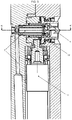
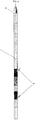
- a device (50) having a housing (11), a drill bit assembly and rotation means (14).
- the drill bit assembly is arranged in the housing (11) and connected to the rotation means (14).
- the drill bit assembly comprises a drill sleeve (12) in the form of a tubular element with a top plate (6), a drill bit (1) and a drill seal (2).
- the drill bit (1) and the drill seal (2) are mounted to the top plate (6).
- the drill seal (2) is arranged around the drill bit (1) at the base of the drill bit (1).
- the base of the drill bit (1) should be understood as the position where the drill bit (1) intersects the top plate (6).
- the drill bit (1) has a conical shaped front end (4) and a back end (5) penetrating the top plate (6).
- Helical grooves (3) are extending along the outside surface of the drill bit (1) from the front end (4) to the back end (5). Further the drill bit (1) has cutting edges at the front end (4) and along the helical grooves (3).
- the drill bit (1) could be interpreted as a twist drill.
- the rotating means (14) are connected to the drill sleeve (12) of the drill bit assembly by means of a gear (15) e.g. a spur wheel/gear. When activated, the rotation means (14) rotate the drill sleeve (12) causing the drill bit (1) and drill seal (2) to rotate.
- the rotation means could e.g. be an electro motor, hydraulics or other means known to a person skilled in the art.
- the drill bit (1) is mounted on the top plate (6) in such a manner, that the grooves (3) extending all the way to the back end (5) of the drill bit (1) is accessible from the back end (5).
- the grooves (3) are either drilling grooves for removing drilling residue or injection grooves for injecting a fluid or fluid mixture.
- the drill bit assembly can be radially advanced from a retracted position inside the housing (11) as shown in FIG. 3 to an extended position as shown in FIG. 1C .
- the drill bit assembly can be retracted to a position inside the housing (11).
- the radial movement of the drill bit assembly can be obtained by various drive means e.g. hydraulic pressure, mechanically or other means known to a person skilled in the art.
- the drill bit assembly is moved by supplying hydraulic pressure to the drill sleeve (12). By applying pressure to and advancing the drill bit assembly drilling operations can be carried out. During drilling operations drilling residue can escape from the drill bit (1) through the drilling grooves (3).
- the size of the drilling residue is among others determined by a combination of the drill bit design, the amount of pressure supplied on the drill bit (1) and the revolution speed. To achieve a satisfactory drilling result the drill bit (1) has special machined cutting edges and a special cutting angle.
- FIG. 2 there is shown a schematic drawing of one embodiment of the drill seal (2) comprising an outer ring (21) e.g. a lip seal and an inner ring (22) e.g. an x-seal.
- an outer ring (21) e.g. a lip seal
- an inner ring (22) e.g. an x-seal.
- injection operations can be carried out.
- a fluid or fluid mixture can be injected through the injection grooves (3) into an annulus of the well or into a formation.
- the fluid or fluid mixture such as amongst others epoxy is supplied from one or more containers inside the housing (11), through the feed channel (7) to the injection grooves (3).
- the device has different containers containing different fluids or fluid mixtures.
- means for mixing (not shown) the supplied fluids are arranged. This could e.g. be a static mixer that by affecting the flow path causes the fluids to be mixed.
- Pressure from the injected fluid or fluid mixture will remove drilling residue that could have built up in the grooves during drilling operations.
- the drill bit can be rotated to remove blocking material.
- the part of the feed channel (7) connected to the back end (5) of the drill bit (1) is extended as the drill bit (1) moves in a radial direction. This is accomplished by the drill sleeve (12) moving relatively to the feed channel sleeve (13). As the drill bit (1) moves toward the extended position the overlap between the drill sleeve (12) and the feed channel sleeve (13) is gradually reduced, increasing the total length of the feed channel.
- a sensor system is incorporated in the device (50).
- the sensor system is used to avoid damaging the drill seal (2) by simultaneously rotating and pressing it against the inner surface of the well tubular (20).
- the rotation of the drill bit assembly is stopped at a predetermined position.
- the drill bit assembly is then advanced and the drill seal (20) is pressed against the inner surface of the well tubular (20) to engage in a fluid tight seal with the well tubular (20).
- the sensor system is a magnetic sensor system comprising a magnet (not shown) rigidly connected to the drill sleeve (12) and a sensor (not shown) arranged inside the housing (11) for detecting the exact position of the drill bit (1) in a radial direction. It would however be obvious to a person skilled in the art, that the above described sensor system could be created in many different ways.
- the device suitable for operating inside a well is inserted into a well tubular by conventional means such as a coiled tubing, drill string or the like known to a person skilled in the art, and will therefore not be described in any further detail.
- the jacking arms (41) are extended from the housing (11), see e.g. FIG. 4 .
- the purpose of the jacking arms (41) is to fixate the device inside the well tubular during drilling and injection operations.
- the device is pressed against the inner surface of the well tubular drilling operations can be commenced by moving the drill bit assembly in a radial direction towards the inner surface of the well tubular (20). By rotating and gradually advancing the drill bit, the cutting edge of the drill bit is capable of drilling through the well tubular (20).
- the drill seal (2) is pressed against the inner surface of the well tubular (20) by further advancing the drill bit assembly.
- the fluid tight flow passage created through the injection channels (3) of the drill bit (1) can thus be used for injecting a fluid or fluid mixture into an annular space.
- a fluid or fluid mixture such as epoxy is supplied under pressure to the back end (5) of the drill bit (1), the fluid or fluid mixture will flow through the injection grooves (3) and into an annular space surrounding the well.
- the drill bit (1) is retracted to a position inside the housing (11) as shown in FIG. 3 .
- the jacking arms (41) are retracted and the device is no longer fixated inside the well tubular.
- the device can then be moved to perform operations is a different position or pulled out of the well and prepared for subsequent redeployment.
- drilling device is not limited to well tubulars.
- the drilling device could also be used in other tubular structures such as but not limited to piping systems, sewage pipes, water pipes, waste pipes, downpipes, ventilation shafts, chimneys, wind turbine towers, tunnels or narrow shafts.
Landscapes
- Engineering & Computer Science (AREA)
- Geology (AREA)
- Life Sciences & Earth Sciences (AREA)
- Mining & Mineral Resources (AREA)
- Environmental & Geological Engineering (AREA)
- Fluid Mechanics (AREA)
- Physics & Mathematics (AREA)
- General Life Sciences & Earth Sciences (AREA)
- Geochemistry & Mineralogy (AREA)
- Mechanical Engineering (AREA)
- Earth Drilling (AREA)
- Processing Of Stones Or Stones Resemblance Materials (AREA)
- Drilling And Boring (AREA)
- Drilling Tools (AREA)
- Perforating, Stamping-Out Or Severing By Means Other Than Cutting (AREA)
Claims (20)
- Vorrichtung (50) zum Bohren eines Lochs in ein Bohrlochrohr (20) und zum nachfolgenden Injizieren eines Fluids oder Fluidgemisches in einen ringförmigen Raum oder eine Formation, welche das Bohrlochrohr (20) umgeben, welche Vorrichtung umfasst:(a) ein Gehäuse (11);(b) eine im Inneren des Gehäuses angeordnete Bohrmeißelanordnung, welche Bohrmeißelanordnung umfasst:- einen eine oder mehrere Schneidkanten sowie Nuten (3) aufweisenden Bohrmeißel (1), wobei die eine oder mehrere Schneidkanten und Nuten (3) sich entlang der Außenfläche des Bohrmeißels (1) erstrecken;(c) mit der Bohrmeißelanordnung verbundene Rotationsmittel (14), welche Rotationsmittel (14) zum Rotieren der Bohrmeißelanordnung fähig sind;(d) eine Fluidversorgung zur Versorgung eines Fluids oder Fluidgemisches in die Nuten (3) des rotierenden Bohrmeißels (1);(e) Antriebsmittel zum Vorschieben der Bohrmeißelanordnung in Richtung des Bohrlochrohres (20), dadurch gekennzeichnet, dass(f) die eine oder mehrere Schneidkanten und Nuten (3) sich entlang der Außenfläche des Bohrmeißels (1) vom Vorderende (4) zum hinteren Ende (5) erstrecken;(g) eine den Bohrmeißel (1) umgebende Bohrdichtung (2) zur Abdichtung der Vorrichtung gegen das Bohrlochrohr (20), welche Bohrdichtung (2) zum Herstellen einer Fluidverbindung fähig ist, die sich vom hinteren Ende (5) durch die Injektionsnuten (3) und in einen ringförmigen Raum oder in eine Formation, welche den Brunnen umgeben, erstreckt.
- Vorrichtung nach Anspruch 1, wobei die sich entlang der Außenfläche des Bohrmeißels (1) erstreckenden Nuten (3) spiralförmige Nuten sind.
- Vorrichtung nach einem der vorhergehenden Ansprüche, wobei die Fluidversorgung zur Versorgung eines Fluids oder Fluidgemisches in die Nuten (3) mit einem im Inneren des Gehäuses befindlichen Behälter in Fluidverbindung steht, welcher Behälter zur Beinhaltung eines Fluids oder Fluidgemisches geeignet ist.
- Vorrichtung nach einem der vorhergehenden Ansprüche, wobei die Fluidversorgung zur Versorgung eines Fluids oder Fluidgemisches in die Nuten (3) mit im Inneren des Gehäuses befindlichen Behältern in Fluidverbindung steht, welche Behälter zur Beinhaltung verschiedener Fluide oder Fluidgemische geeignet sind.
- Vorrichtung nach einem der vorhergehenden Ansprüche, wobei die Fluidversorgung zur Versorgung eines Fluids oder Fluidgemisches in die Nuten (3) durch einen Zuführungskanal (7) mit dem der Schneidkante entgegengesetzten Ende des Bohrmeißels (1) verbunden ist, so dass Fluid von der Vorrichtung über die Nuten (3) und in den ringförmigen Raum förderbar ist, während der Bohrmeißel (1) sich durch das Bohrlochrohr (20) hindurchstreckt.
- Vorrichtung nach einem der vorhergehenden Ansprüche, wobei die Vorrichtung eine Bohrhülse (12) und eine Zuführungskanalhülse (13) umfasst, welche Bohrhülse (12) relativ zur Zuführungskanalhülse (13) beweglich ist.
- Vorrichtung nach einem der vorhergehenden Ansprüche 1 bis 5, wobei die Bohrmeißelanordnung eine, mit dem Bohrmeißel (1) und mit den Antriebsmitteln verbundene, rotierbare Bohrhülse (12) umfasst.
- Vorrichtung nach Anspruch 7, wobei die Bohrhülse mit den Rotationsmitteln (14) verbunden ist.
- Vorrichtung nach Anspruch 8, wobei die Bohrdichtung (2) an der Bohrhülse (12) montiert ist.
- Vorrichtung nach einem der vorhergehenden Ansprüche, wobei die Antriebsmittel so ausgelegt sind, dass sie die Bohrmeißelanordnung zurückziehen können.
- Vorrichtung nach einem der vorhergehenden Ansprüche, wobei der Druck des injizierten Fluids die Dichtwirkung der Bohrdichtung (2) beim Injizieren des Fluids oder Fluidgemisches verstärken wird.
- Vorrichtung nach einem der vorhergehenden Ansprüche, wobei die Bohrdichtung (2) konvergierende Innenflächen aufweist.
- Vorrichtung nach einem der vorhergehenden Ansprüche, umfassend einen Sensor zur Bestimmung der Position des Bohrmeißels (1) in einer Radialrichtung.
- Vorrichtung nach Anspruch 13 in Abhängigkeit von Anspruch 6 oder 7 oder 8 oder 9, wobei der Sensor ein magnetischer Sensor ist, welcher einen an der Bohrhülse (12) starr montierten Magneten und einen im Inneren des Gehäuses angeordneten Sensor zur Erkennung der Position des Magneten umfasst.
- Vorrichtung nach Anspruch 11, wobei die Bohrdichtung (2) am Gehäuse montiert ist.
- Vorrichtung nach einem der vorhergehenden Ansprüche, umfassend Mittel zum Pressen der Vorrichtung gegen die Innenfläche des Bohrlochrohres (20).
- Verwendung einer Vorrichtung nach einem der vorhergehenden Ansprüche, dadurch gekennzeichnet, dass die Verwendung der Vorrichtung zur Durchführung von Arbeitsabläufen im Inneren eines Bohrlochrohres (20) dient.
- Verwendung einer Vorrichtung nach Anspruch 16, zum Injizieren eines Fluids oder Fluidgemisches durch eine Perforierung in der Oberfläche eines Bohrlochrohres (20).
- Bohrmeißel (1) zur Verwendung mit der Vorrichtung nach einem der Ansprüche 1 bis 8, dadurch gekennzeichnet, dass der Bohrmeißel (1) Schneidkanten und Nuten (3) aufweist, die sich entlang seiner Außenfläche vom Vorderende (4) zum hinteren Ende (5) erstrecken, welcher Bohrmeißel (1) ferner eine montierte Peripherie-Bohrdichtung (2) aufweist.
- Verfahren zum Injizieren eines Fluids in eine Formation durch die Verwendung der Vorrichtung nach einem der Ansprüche 1 bis 16,
dadurch gekennzeichnet, dass ein Loch in ein Bohrlochrohr (20) durch die Verwendung des Bohrmeißels (1) gebohrt wird, welcher Schneidkanten und Nuten (3) aufweist, die sich entlang seiner Außenfläche vom Vorderende (4) zum hinteren Ende (5) erstrecken, und wobei das Fluid durch die Nuten (3) injiziert wird, während der Bohrmeißel (1) sich durch das Bohrlochrohr hindurchstreckt.
Applications Claiming Priority (3)
| Application Number | Priority Date | Filing Date | Title |
|---|---|---|---|
| US26104509P | 2009-11-13 | 2009-11-13 | |
| DKPA200970204A DK178544B1 (en) | 2009-11-13 | 2009-11-13 | Injektionsborebit |
| PCT/EP2010/067129 WO2011058014A1 (en) | 2009-11-13 | 2010-11-09 | Injection drill bit |
Publications (2)
| Publication Number | Publication Date |
|---|---|
| EP2499321A1 EP2499321A1 (de) | 2012-09-19 |
| EP2499321B1 true EP2499321B1 (de) | 2017-09-27 |
Family
ID=42269938
Family Applications (1)
| Application Number | Title | Priority Date | Filing Date |
|---|---|---|---|
| EP10774225.6A Active EP2499321B1 (de) | 2009-11-13 | 2010-11-09 | Injektionsbohrmeissel |
Country Status (8)
| Country | Link |
|---|---|
| US (1) | US9097109B2 (de) |
| EP (1) | EP2499321B1 (de) |
| CN (1) | CN102812201B (de) |
| CA (1) | CA2785702C (de) |
| DK (1) | DK178544B1 (de) |
| EA (1) | EA023414B1 (de) |
| NO (1) | NO2499321T3 (de) |
| WO (1) | WO2011058014A1 (de) |
Families Citing this family (11)
| Publication number | Priority date | Publication date | Assignee | Title |
|---|---|---|---|---|
| RU2515669C2 (ru) * | 2012-08-27 | 2014-05-20 | Пассербай Инк | Гидромеханический перфоратор (варианты) |
| DK2909427T3 (da) | 2012-10-16 | 2019-11-25 | Total E&P Danmark As | Tætningsanordning og -fremgangsmåde |
| GB2523751A (en) | 2014-03-03 | 2015-09-09 | Maersk Olie & Gas | Method for managing production of hydrocarbons from a subterranean reservoir |
| DK3502411T3 (en) * | 2014-08-21 | 2021-05-03 | Agat Tech As | Anchoring module for well tools |
| RU2597392C1 (ru) * | 2015-05-15 | 2016-09-10 | Федеральное государственное бюджетное образовательное учреждение высшего образования "Уфимский государственный нефтяной технический университет" | Перфоратор щелевой для обсаженных скважин |
| CN109312096B (zh) | 2016-06-21 | 2022-05-24 | 3M创新有限公司 | 包含聚乳酸聚合物、聚乙酸乙烯酯聚合物和增塑剂的泡沫组合物、制品及其制备和使用方法 |
| NO20161434A1 (en) * | 2016-09-09 | 2018-03-12 | Tyrfing Innovation As | A hole forming tool |
| GB201813865D0 (en) | 2018-08-24 | 2018-10-10 | Westerton Uk Ltd | Downhole cutting tool and anchor arrangement |
| US11384633B2 (en) | 2019-05-20 | 2022-07-12 | Caterpillar Global Mining Equipment Llc | Drill head position determination system |
| US11401754B2 (en) | 2020-01-17 | 2022-08-02 | Caterpillar Global Mining Equipment Llc | Systems and methods for drill head position determination |
| NO347022B1 (en) * | 2021-10-07 | 2023-04-17 | Altus Intervention Tech As | Radial Drilling Unit |
Family Cites Families (22)
| Publication number | Priority date | Publication date | Assignee | Title |
|---|---|---|---|---|
| US2381929A (en) * | 1940-09-06 | 1945-08-14 | Schlumberger Marcel | Well conditioning apparatus |
| US2516421A (en) * | 1945-08-06 | 1950-07-25 | Jerry B Robertson | Drilling tool |
| US2725283A (en) * | 1952-04-30 | 1955-11-29 | Exxon Research Engineering Co | Apparatus for logging well bores |
| US3301337A (en) * | 1964-05-05 | 1967-01-31 | Alpha Trace Inc | Apparatus for completing a well |
| US4368786A (en) * | 1981-04-02 | 1983-01-18 | Cousins James E | Downhole drilling apparatus |
| US5183111A (en) * | 1991-08-20 | 1993-02-02 | Schellstede Herman J | Extended reach penetrating tool and method of forming a radial hole in a well casing |
| US5692565A (en) * | 1996-02-20 | 1997-12-02 | Schlumberger Technology Corporation | Apparatus and method for sampling an earth formation through a cased borehole |
| US6283230B1 (en) * | 1999-03-01 | 2001-09-04 | Jasper N. Peters | Method and apparatus for lateral well drilling utilizing a rotating nozzle |
| US6260623B1 (en) * | 1999-07-30 | 2001-07-17 | Kmk Trust | Apparatus and method for utilizing flexible tubing with lateral bore holes |
| NO312255B1 (no) | 2000-06-28 | 2002-04-15 | Pgs Reservoir Consultants As | Verktöy for gjennomhulling av et langsgående veggparti av et fôringsrör |
| US6523624B1 (en) * | 2001-01-10 | 2003-02-25 | James E. Cousins | Sectional drive system |
| US6772839B1 (en) * | 2001-10-22 | 2004-08-10 | Lesley O. Bond | Method and apparatus for mechanically perforating a well casing or other tubular structure for testing, stimulation or other remedial operations |
| JP2007529745A (ja) * | 2004-03-17 | 2007-10-25 | ベイカー ヒューズ インコーポレイテッド | 油層流体の性質を特定するための孔内流体の分析方法及び装置 |
| US7380599B2 (en) * | 2004-06-30 | 2008-06-03 | Schlumberger Technology Corporation | Apparatus and method for characterizing a reservoir |
| US7347284B2 (en) * | 2004-10-20 | 2008-03-25 | Halliburton Energy Services, Inc. | Apparatus and method for hard rock sidewall coring of a borehole |
| US7278480B2 (en) * | 2005-03-31 | 2007-10-09 | Schlumberger Technology Corporation | Apparatus and method for sensing downhole parameters |
| CN2929183Y (zh) * | 2006-07-18 | 2007-08-01 | 中国石油天然气股份有限公司 | 一种液控式井下多级测试器 |
| US7690443B2 (en) | 2006-11-20 | 2010-04-06 | Charles Brunet | Apparatus, system, and method for casing hole formation in radial drilling operations |
| US7654321B2 (en) * | 2006-12-27 | 2010-02-02 | Schlumberger Technology Corporation | Formation fluid sampling apparatus and methods |
| US7594541B2 (en) * | 2006-12-27 | 2009-09-29 | Schlumberger Technology Corporation | Pump control for formation testing |
| US7905286B2 (en) * | 2008-10-01 | 2011-03-15 | Baker Hughes Incorporated | Method and apparatus for sealing a hole made with a cased hole formation tester |
| GB2474280A (en) * | 2009-10-09 | 2011-04-13 | Cutting & Wear Resistant Dev | Cutting tool insert with ridges and troughs |
-
2009
- 2009-11-13 DK DKPA200970204A patent/DK178544B1/da active
-
2010
- 2010-11-09 EP EP10774225.6A patent/EP2499321B1/de active Active
- 2010-11-09 CA CA2785702A patent/CA2785702C/en active Active
- 2010-11-09 US US13/509,517 patent/US9097109B2/en active Active
- 2010-11-09 WO PCT/EP2010/067129 patent/WO2011058014A1/en not_active Ceased
- 2010-11-09 EA EA201290335A patent/EA023414B1/ru not_active IP Right Cessation
- 2010-11-09 NO NO10774225A patent/NO2499321T3/no unknown
- 2010-11-09 CN CN201080061196.5A patent/CN102812201B/zh active Active
Non-Patent Citations (1)
| Title |
|---|
| None * |
Also Published As
| Publication number | Publication date |
|---|---|
| DK178544B1 (en) | 2016-06-13 |
| CN102812201A (zh) | 2012-12-05 |
| DK200970204A (en) | 2011-05-14 |
| US9097109B2 (en) | 2015-08-04 |
| EA023414B1 (ru) | 2016-06-30 |
| EP2499321A1 (de) | 2012-09-19 |
| CA2785702A1 (en) | 2011-05-19 |
| WO2011058014A1 (en) | 2011-05-19 |
| CA2785702C (en) | 2017-11-07 |
| CN102812201B (zh) | 2015-07-29 |
| NO2499321T3 (de) | 2018-02-24 |
| US20120279710A1 (en) | 2012-11-08 |
| EA201290335A1 (ru) | 2012-12-28 |
Similar Documents
| Publication | Publication Date | Title |
|---|---|---|
| CA2785702C (en) | Injection drill bit | |
| EP2499326B1 (de) | Vortriebseinheiten und bälge für bohrlochwerkzeuge | |
| RU2390623C2 (ru) | Однорейсовое скважинное устройство, снабженное средствами борьбы с пескопроявлением | |
| EP3969718B1 (de) | Stanz- und einspritzwerkzeug für bohrlochgehäuse und verfahren zu dessen verwendung | |
| CA2861490C (en) | Limited depth abrasive jet cutter | |
| US6880648B2 (en) | Apparatus and method for directional drilling of holes | |
| EP3068970B1 (de) | Einzelauslöser-schneid- und zugsystem sowie vorrichtung | |
| EP3908732B1 (de) | Bohrlochverfahren | |
| AU2013357099B2 (en) | Mixing tool for treating a portion of soil | |
| JP2024528408A (ja) | 一体化された穿孔注入及び抽出のデバイス及び方法 | |
| CN100462522C (zh) | 突出煤层保压钻进切缝设备及其方法 | |
| JP2016075139A (ja) | 回転貫入杭及び回転貫入杭を使用する根固めされた基礎の施工方法 | |
| CN104145081A (zh) | 锚杆机 | |
| CN208073389U (zh) | 一种煤矿工作面防治水导入装置 | |
| CN111434883A (zh) | 一种油管打孔装置 | |
| CN117431946A (zh) | 一种深基坑地下连续墙管涌修复装置及方法 | |
| BR112020004033A2 (pt) | ferramenta de fresagem |
Legal Events
| Date | Code | Title | Description |
|---|---|---|---|
| PUAI | Public reference made under article 153(3) epc to a published international application that has entered the european phase |
Free format text: ORIGINAL CODE: 0009012 |
|
| 17P | Request for examination filed |
Effective date: 20120613 |
|
| AK | Designated contracting states |
Kind code of ref document: A1 Designated state(s): AL AT BE BG CH CY CZ DE DK EE ES FI FR GB GR HR HU IE IS IT LI LT LU LV MC MK MT NL NO PL PT RO RS SE SI SK SM TR |
|
| DAX | Request for extension of the european patent (deleted) | ||
| GRAP | Despatch of communication of intention to grant a patent |
Free format text: ORIGINAL CODE: EPIDOSNIGR1 |
|
| INTG | Intention to grant announced |
Effective date: 20161221 |
|
| GRAJ | Information related to disapproval of communication of intention to grant by the applicant or resumption of examination proceedings by the epo deleted |
Free format text: ORIGINAL CODE: EPIDOSDIGR1 |
|
| GRAP | Despatch of communication of intention to grant a patent |
Free format text: ORIGINAL CODE: EPIDOSNIGR1 |
|
| INTC | Intention to grant announced (deleted) | ||
| INTG | Intention to grant announced |
Effective date: 20170509 |
|
| GRAS | Grant fee paid |
Free format text: ORIGINAL CODE: EPIDOSNIGR3 |
|
| GRAA | (expected) grant |
Free format text: ORIGINAL CODE: 0009210 |
|
| AK | Designated contracting states |
Kind code of ref document: B1 Designated state(s): AL AT BE BG CH CY CZ DE DK EE ES FI FR GB GR HR HU IE IS IT LI LT LU LV MC MK MT NL NO PL PT RO RS SE SI SK SM TR |
|
| REG | Reference to a national code |
Ref country code: GB Ref legal event code: FG4D |
|
| REG | Reference to a national code |
Ref country code: CH Ref legal event code: EP |
|
| REG | Reference to a national code |
Ref country code: AT Ref legal event code: REF Ref document number: 932140 Country of ref document: AT Kind code of ref document: T Effective date: 20171015 |
|
| REG | Reference to a national code |
Ref country code: IE Ref legal event code: FG4D |
|
| REG | Reference to a national code |
Ref country code: DE Ref legal event code: R096 Ref document number: 602010045576 Country of ref document: DE |
|
| REG | Reference to a national code |
Ref country code: FR Ref legal event code: PLFP Year of fee payment: 8 |
|
| REG | Reference to a national code |
Ref country code: NL Ref legal event code: FP |
|
| PG25 | Lapsed in a contracting state [announced via postgrant information from national office to epo] |
Ref country code: LT Free format text: LAPSE BECAUSE OF FAILURE TO SUBMIT A TRANSLATION OF THE DESCRIPTION OR TO PAY THE FEE WITHIN THE PRESCRIBED TIME-LIMIT Effective date: 20170927 Ref country code: SE Free format text: LAPSE BECAUSE OF FAILURE TO SUBMIT A TRANSLATION OF THE DESCRIPTION OR TO PAY THE FEE WITHIN THE PRESCRIBED TIME-LIMIT Effective date: 20170927 Ref country code: FI Free format text: LAPSE BECAUSE OF FAILURE TO SUBMIT A TRANSLATION OF THE DESCRIPTION OR TO PAY THE FEE WITHIN THE PRESCRIBED TIME-LIMIT Effective date: 20170927 Ref country code: HR Free format text: LAPSE BECAUSE OF FAILURE TO SUBMIT A TRANSLATION OF THE DESCRIPTION OR TO PAY THE FEE WITHIN THE PRESCRIBED TIME-LIMIT Effective date: 20170927 |
|
| REG | Reference to a national code |
Ref country code: LT Ref legal event code: MG4D |
|
| REG | Reference to a national code |
Ref country code: AT Ref legal event code: MK05 Ref document number: 932140 Country of ref document: AT Kind code of ref document: T Effective date: 20170927 |
|
| REG | Reference to a national code |
Ref country code: NO Ref legal event code: T2 Effective date: 20170927 |
|
| PG25 | Lapsed in a contracting state [announced via postgrant information from national office to epo] |
Ref country code: RS Free format text: LAPSE BECAUSE OF FAILURE TO SUBMIT A TRANSLATION OF THE DESCRIPTION OR TO PAY THE FEE WITHIN THE PRESCRIBED TIME-LIMIT Effective date: 20170927 Ref country code: BG Free format text: LAPSE BECAUSE OF FAILURE TO SUBMIT A TRANSLATION OF THE DESCRIPTION OR TO PAY THE FEE WITHIN THE PRESCRIBED TIME-LIMIT Effective date: 20171227 Ref country code: LV Free format text: LAPSE BECAUSE OF FAILURE TO SUBMIT A TRANSLATION OF THE DESCRIPTION OR TO PAY THE FEE WITHIN THE PRESCRIBED TIME-LIMIT Effective date: 20170927 Ref country code: GR Free format text: LAPSE BECAUSE OF FAILURE TO SUBMIT A TRANSLATION OF THE DESCRIPTION OR TO PAY THE FEE WITHIN THE PRESCRIBED TIME-LIMIT Effective date: 20171228 |
|
| PG25 | Lapsed in a contracting state [announced via postgrant information from national office to epo] |
Ref country code: ES Free format text: LAPSE BECAUSE OF FAILURE TO SUBMIT A TRANSLATION OF THE DESCRIPTION OR TO PAY THE FEE WITHIN THE PRESCRIBED TIME-LIMIT Effective date: 20170927 Ref country code: RO Free format text: LAPSE BECAUSE OF FAILURE TO SUBMIT A TRANSLATION OF THE DESCRIPTION OR TO PAY THE FEE WITHIN THE PRESCRIBED TIME-LIMIT Effective date: 20170927 Ref country code: CZ Free format text: LAPSE BECAUSE OF FAILURE TO SUBMIT A TRANSLATION OF THE DESCRIPTION OR TO PAY THE FEE WITHIN THE PRESCRIBED TIME-LIMIT Effective date: 20170927 |
|
| PG25 | Lapsed in a contracting state [announced via postgrant information from national office to epo] |
Ref country code: AT Free format text: LAPSE BECAUSE OF FAILURE TO SUBMIT A TRANSLATION OF THE DESCRIPTION OR TO PAY THE FEE WITHIN THE PRESCRIBED TIME-LIMIT Effective date: 20170927 Ref country code: SM Free format text: LAPSE BECAUSE OF FAILURE TO SUBMIT A TRANSLATION OF THE DESCRIPTION OR TO PAY THE FEE WITHIN THE PRESCRIBED TIME-LIMIT Effective date: 20170927 Ref country code: SK Free format text: LAPSE BECAUSE OF FAILURE TO SUBMIT A TRANSLATION OF THE DESCRIPTION OR TO PAY THE FEE WITHIN THE PRESCRIBED TIME-LIMIT Effective date: 20170927 Ref country code: EE Free format text: LAPSE BECAUSE OF FAILURE TO SUBMIT A TRANSLATION OF THE DESCRIPTION OR TO PAY THE FEE WITHIN THE PRESCRIBED TIME-LIMIT Effective date: 20170927 Ref country code: IS Free format text: LAPSE BECAUSE OF FAILURE TO SUBMIT A TRANSLATION OF THE DESCRIPTION OR TO PAY THE FEE WITHIN THE PRESCRIBED TIME-LIMIT Effective date: 20180127 Ref country code: IT Free format text: LAPSE BECAUSE OF FAILURE TO SUBMIT A TRANSLATION OF THE DESCRIPTION OR TO PAY THE FEE WITHIN THE PRESCRIBED TIME-LIMIT Effective date: 20170927 |
|
| REG | Reference to a national code |
Ref country code: DE Ref legal event code: R097 Ref document number: 602010045576 Country of ref document: DE |
|
| PG25 | Lapsed in a contracting state [announced via postgrant information from national office to epo] |
Ref country code: MC Free format text: LAPSE BECAUSE OF FAILURE TO SUBMIT A TRANSLATION OF THE DESCRIPTION OR TO PAY THE FEE WITHIN THE PRESCRIBED TIME-LIMIT Effective date: 20170927 |
|
| PG25 | Lapsed in a contracting state [announced via postgrant information from national office to epo] |
Ref country code: LI Free format text: LAPSE BECAUSE OF NON-PAYMENT OF DUE FEES Effective date: 20171130 Ref country code: CH Free format text: LAPSE BECAUSE OF NON-PAYMENT OF DUE FEES Effective date: 20171130 Ref country code: DK Free format text: LAPSE BECAUSE OF FAILURE TO SUBMIT A TRANSLATION OF THE DESCRIPTION OR TO PAY THE FEE WITHIN THE PRESCRIBED TIME-LIMIT Effective date: 20170927 |
|
| PLBE | No opposition filed within time limit |
Free format text: ORIGINAL CODE: 0009261 |
|
| STAA | Information on the status of an ep patent application or granted ep patent |
Free format text: STATUS: NO OPPOSITION FILED WITHIN TIME LIMIT |
|
| PG25 | Lapsed in a contracting state [announced via postgrant information from national office to epo] |
Ref country code: LU Free format text: LAPSE BECAUSE OF NON-PAYMENT OF DUE FEES Effective date: 20171109 Ref country code: PL Free format text: LAPSE BECAUSE OF FAILURE TO SUBMIT A TRANSLATION OF THE DESCRIPTION OR TO PAY THE FEE WITHIN THE PRESCRIBED TIME-LIMIT Effective date: 20170927 |
|
| REG | Reference to a national code |
Ref country code: BE Ref legal event code: MM Effective date: 20171130 |
|
| 26N | No opposition filed |
Effective date: 20180628 |
|
| REG | Reference to a national code |
Ref country code: IE Ref legal event code: MM4A |
|
| PG25 | Lapsed in a contracting state [announced via postgrant information from national office to epo] |
Ref country code: MT Free format text: LAPSE BECAUSE OF NON-PAYMENT OF DUE FEES Effective date: 20171109 |
|
| REG | Reference to a national code |
Ref country code: FR Ref legal event code: PLFP Year of fee payment: 9 |
|
| PG25 | Lapsed in a contracting state [announced via postgrant information from national office to epo] |
Ref country code: IE Free format text: LAPSE BECAUSE OF NON-PAYMENT OF DUE FEES Effective date: 20171109 |
|
| PG25 | Lapsed in a contracting state [announced via postgrant information from national office to epo] |
Ref country code: BE Free format text: LAPSE BECAUSE OF NON-PAYMENT OF DUE FEES Effective date: 20171130 Ref country code: SI Free format text: LAPSE BECAUSE OF FAILURE TO SUBMIT A TRANSLATION OF THE DESCRIPTION OR TO PAY THE FEE WITHIN THE PRESCRIBED TIME-LIMIT Effective date: 20170927 |
|
| PG25 | Lapsed in a contracting state [announced via postgrant information from national office to epo] |
Ref country code: HU Free format text: LAPSE BECAUSE OF FAILURE TO SUBMIT A TRANSLATION OF THE DESCRIPTION OR TO PAY THE FEE WITHIN THE PRESCRIBED TIME-LIMIT; INVALID AB INITIO Effective date: 20101109 |
|
| PG25 | Lapsed in a contracting state [announced via postgrant information from national office to epo] |
Ref country code: CY Free format text: LAPSE BECAUSE OF NON-PAYMENT OF DUE FEES Effective date: 20170927 |
|
| PG25 | Lapsed in a contracting state [announced via postgrant information from national office to epo] |
Ref country code: MK Free format text: LAPSE BECAUSE OF FAILURE TO SUBMIT A TRANSLATION OF THE DESCRIPTION OR TO PAY THE FEE WITHIN THE PRESCRIBED TIME-LIMIT Effective date: 20170927 |
|
| PG25 | Lapsed in a contracting state [announced via postgrant information from national office to epo] |
Ref country code: TR Free format text: LAPSE BECAUSE OF FAILURE TO SUBMIT A TRANSLATION OF THE DESCRIPTION OR TO PAY THE FEE WITHIN THE PRESCRIBED TIME-LIMIT Effective date: 20170927 |
|
| PG25 | Lapsed in a contracting state [announced via postgrant information from national office to epo] |
Ref country code: PT Free format text: LAPSE BECAUSE OF FAILURE TO SUBMIT A TRANSLATION OF THE DESCRIPTION OR TO PAY THE FEE WITHIN THE PRESCRIBED TIME-LIMIT Effective date: 20170927 |
|
| PG25 | Lapsed in a contracting state [announced via postgrant information from national office to epo] |
Ref country code: AL Free format text: LAPSE BECAUSE OF FAILURE TO SUBMIT A TRANSLATION OF THE DESCRIPTION OR TO PAY THE FEE WITHIN THE PRESCRIBED TIME-LIMIT Effective date: 20170927 |
|
| P01 | Opt-out of the competence of the unified patent court (upc) registered |
Effective date: 20230524 |
|
| PGFP | Annual fee paid to national office [announced via postgrant information from national office to epo] |
Ref country code: NL Payment date: 20241120 Year of fee payment: 15 |
|
| PGFP | Annual fee paid to national office [announced via postgrant information from national office to epo] |
Ref country code: DE Payment date: 20241121 Year of fee payment: 15 |
|
| PGFP | Annual fee paid to national office [announced via postgrant information from national office to epo] |
Ref country code: NO Payment date: 20241125 Year of fee payment: 15 |
|
| PGFP | Annual fee paid to national office [announced via postgrant information from national office to epo] |
Ref country code: GB Payment date: 20241120 Year of fee payment: 15 |
|
| PGFP | Annual fee paid to national office [announced via postgrant information from national office to epo] |
Ref country code: FR Payment date: 20241128 Year of fee payment: 15 |