EP2498996B1 - Portable device and method for printing an image, data storage medium, pen and bench mark for said device - Google Patents
Portable device and method for printing an image, data storage medium, pen and bench mark for said device Download PDFInfo
- Publication number
- EP2498996B1 EP2498996B1 EP20100774237 EP10774237A EP2498996B1 EP 2498996 B1 EP2498996 B1 EP 2498996B1 EP 20100774237 EP20100774237 EP 20100774237 EP 10774237 A EP10774237 A EP 10774237A EP 2498996 B1 EP2498996 B1 EP 2498996B1
- Authority
- EP
- European Patent Office
- Prior art keywords
- pen
- image
- printing
- benchmark
- substrate
- Prior art date
- Legal status (The legal status is an assumption and is not a legal conclusion. Google has not performed a legal analysis and makes no representation as to the accuracy of the status listed.)
- Not-in-force
Links
Images


Classifications
-
- G—PHYSICS
- G06—COMPUTING; CALCULATING OR COUNTING
- G06F—ELECTRIC DIGITAL DATA PROCESSING
- G06F3/00—Input arrangements for transferring data to be processed into a form capable of being handled by the computer; Output arrangements for transferring data from processing unit to output unit, e.g. interface arrangements
- G06F3/01—Input arrangements or combined input and output arrangements for interaction between user and computer
- G06F3/03—Arrangements for converting the position or the displacement of a member into a coded form
- G06F3/033—Pointing devices displaced or positioned by the user, e.g. mice, trackballs, pens or joysticks; Accessories therefor
- G06F3/0354—Pointing devices displaced or positioned by the user, e.g. mice, trackballs, pens or joysticks; Accessories therefor with detection of 2D relative movements between the device, or an operating part thereof, and a plane or surface, e.g. 2D mice, trackballs, pens or pucks
- G06F3/03545—Pens or stylus
-
- B—PERFORMING OPERATIONS; TRANSPORTING
- B41—PRINTING; LINING MACHINES; TYPEWRITERS; STAMPS
- B41J—TYPEWRITERS; SELECTIVE PRINTING MECHANISMS, i.e. MECHANISMS PRINTING OTHERWISE THAN FROM A FORME; CORRECTION OF TYPOGRAPHICAL ERRORS
- B41J3/00—Typewriters or selective printing or marking mechanisms characterised by the purpose for which they are constructed
- B41J3/36—Typewriters or selective printing or marking mechanisms characterised by the purpose for which they are constructed for portability, i.e. hand-held printers or laptop printers
-
- G—PHYSICS
- G06—COMPUTING; CALCULATING OR COUNTING
- G06F—ELECTRIC DIGITAL DATA PROCESSING
- G06F3/00—Input arrangements for transferring data to be processed into a form capable of being handled by the computer; Output arrangements for transferring data from processing unit to output unit, e.g. interface arrangements
- G06F3/01—Input arrangements or combined input and output arrangements for interaction between user and computer
- G06F3/03—Arrangements for converting the position or the displacement of a member into a coded form
- G06F3/033—Pointing devices displaced or positioned by the user, e.g. mice, trackballs, pens or joysticks; Accessories therefor
- G06F3/0346—Pointing devices displaced or positioned by the user, e.g. mice, trackballs, pens or joysticks; Accessories therefor with detection of the device orientation or free movement in a 3D space, e.g. 3D mice, 6-DOF [six degrees of freedom] pointers using gyroscopes, accelerometers or tilt-sensors
-
- G—PHYSICS
- G06—COMPUTING; CALCULATING OR COUNTING
- G06F—ELECTRIC DIGITAL DATA PROCESSING
- G06F3/00—Input arrangements for transferring data to be processed into a form capable of being handled by the computer; Output arrangements for transferring data from processing unit to output unit, e.g. interface arrangements
- G06F3/01—Input arrangements or combined input and output arrangements for interaction between user and computer
- G06F3/03—Arrangements for converting the position or the displacement of a member into a coded form
- G06F3/041—Digitisers, e.g. for touch screens or touch pads, characterised by the transducing means
- G06F3/046—Digitisers, e.g. for touch screens or touch pads, characterised by the transducing means by electromagnetic means
Definitions
- the invention relates to a portable device and a method for printing an image in a printing area arranged on a material support.
- the invention also relates to an information recording medium, a pen and a terminal for the implementation of this printing process.
- the invention relates in particular to "non-contact" printing devices, that is to say devices in which the print head does not come into direct mechanical contact with the medium on which it is printed.
- such a device is disclosed in the patent application US 5,861,877 .
- the position of the pen is measured using an accelerometer or a similar position sensor. The position of the pen is therefore measured relative to its starting point.
- the invention aims to remedy at least one of these disadvantages.
- the positioning of at least one reference mark on the support and the measurement of the position of the pen relative to this reference mark makes it possible to locate the pen in a repository integral with this reference mark.
- the measured position is therefore independent of the starting point of the pen. It is not necessary, in the device above, to position the pen on a specific starting point. It is also possible to resume the printing process at any point in the print area when printing has been interrupted.
- the landmark is mechanically independent of the support.
- the above device therefore allows printing on any medium.
- the invention also relates to an information recording medium comprising instructions for carrying out the method when these instructions are executed by an electronic calculator.
- the invention also relates to a pen for the implementation of the above printing device, this pen incorporating at least a part of the elements of the measuring unit capable of measuring the position of the print head by relative to the terminal and a control unit able to determine the distance separating the pen from the support from the measurement of the position of the print head and to inhibit the printing of the image on the support if this distance is greater than a predetermined threshold.
- control unit for implementing the above device in which this control unit is programmed to determine the distance that separates the pen from the support from the measurement of the position of the the print head and to inhibit the printing of the image on the support if this distance is greater than a predetermined threshold.
- the figure 1 represents a device 2 for printing an image on a horizontal material support 4.
- image designates any type of pattern that can be printed on the support 4.
- These patterns can be in black and white or in gray or in color with color gradients if necessary.
- These patterns can correspond to a photo, a geometric pattern or others.
- the support 4 has a planar and horizontal upper face.
- the support 4 is made of any type of material that can be printed.
- the support 4 is made of a material that can be damaged if it comes into direct contact with a print head.
- it is a flexible and fragile membrane such as human skin, spider web, milk membrane, beer moss ....
- the device 2 is portable, that is to say that it is directly transportable by a human being without resorting to technical lifting means.
- the weight of all the elements of the device 2 is typically less than 10 kg and preferably less than 5 or 1 kg.
- the bulk of all the elements of this device 2 is typically less than 0.15 m 3 and preferably less than 10 -3 or 10 -4 m 3 .
- the device 2 comprises a pen 8 manually movable by an operator over a printing zone 10 arranged on the upper face of the support 4 and inside which the image must be printed.
- the pen 8 must be separated vertically from the support 4 by a height h greater than a threshold S 3 not zero so as not to come into direct contact with the support.
- the printing zone 10 is here rectangular with a width L and a length Lg.
- the pen 8 extends essentially along a longitudinal axis A1.
- the dimensions of the pen 8 are provided so that it is easily manipulated by the hand of the operator.
- the length of the pen 8 is less than 20 cm and its width is less than 5 cm.
- the weight of the pen 8 is typically less than 1 kg and preferably less than 200 g.
- each ink jet nozzle extends substantially parallel to the axis A1.
- the unit 14 is connected to the memory 16.
- the image stored in the memory 16 is encoded, for example, in a standard format such as the "bitmap" format.
- the image to print is a rectangular image.
- the control unit 14 is made from programmable electronic computers capable of executing instructions recorded on a medium information recording.
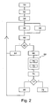
- the memory 16 comprises the instructions necessary for carrying out the method of the figure 2 , when executed by unit 14.
- the interface 18 makes it possible to connect the pen 8 to a computer to record an image to be printed in the memory 16.
- the device 2 also comprises removable marker terminals manually positionable on the support 4.
- the device comprises four markers 20 to 23.
- the terminals 20 to 23 are reported on the support 4 already existing. They are therefore mechanically independent of the support 4 and can be freely positioned on the support 4 by the operator. Here, the terminals are deposited on the support 4 and only held in place on the support 4 by gravity.
- Each of these landmarks is associated with a point of the image to be printed by a predefined relationship independent of the position of the terminal on the support.
- This predefined relation is for example recorded in the memory 16.
- this predefined relation indicates that each of the terminals 20 to 23 corresponds to an angle of the rectangular image to be printed. These terminals thus delimit the printing zone 10.
- the device 2 comprises a unit for measuring the position and orientation of the print head 12 with respect to the markers 20 to 23.
- This unit measures the six degrees of freedom of the print head.
- the position and the orientation of the print head are indicated, respectively, by two coordinate triplets x, y, z and ⁇ x , ⁇ y , ⁇ z expressed in an orthogonal XYZ reference set without any degree.
- the X and Y directions of the reference XYZ are parallel to the upper face of the support 4 while the direction Z extends vertically.
- the angles ⁇ x , ⁇ y and ⁇ z correspond to the angles made by the axis A1, respectively, with the directions X, Y and Z.
- the pen 8 and the terminals 20 to 23 are equipped, respectively, emitters / receivers 30 and 32 of electromagnetic waves.
- transmitters / receivers 30 and 32 are Ultra Wideband wave transmitters / receivers better known by the acronym UWB (Ultra Wide Band).
- UWB Ultra Wide Band
- Each of these emitters / receivers is equipped with a clock making it possible to measure the times of emission and reception of the waves so as to be able to measure the propagation time of the wave between the emitters / receivers 30 and 32.
- the unit 14 is also equipped with a determiner 33 of the distance that separates the pen 8 from each of the terminals 20 to 23 from the measured propagation times.
- the accelerometer 34 and the magnetometer 36 are housed inside the pen 8.
- An accelerometer 38 and a magnetometer 40 are housed inside each of the terminals 20 to 23.
- the accelerometer 34 measures the angle made by the axis A1 with the vertical direction represented by the local direction of the earth's gravity field.
- Magnetometer 36 measures the angle that axis A1 makes with the magnetic north of the Earth's magnetic field.
- the accelerometer 34 and the magnetometer 36 are placed in the part of the pen 8 farthest from the print head 12 so as to increase the accuracy of the measurement of the orientation of the axis A1.
- the accelerometer 38 measures the angle that makes an A2 axis integral with the marker terminal with the vertical.
- Magnetometer 40 measures the angle this axis A2 makes with magnetic north.
- each reference terminal is shaped so that when it is deposited on the support 4, the axis A2 is systematically perpendicular to the upper face of the support 4.
- each of the reference markers comprises at least one plane face perpendicular to the axis A2 and intended to be directly resting on the upper face of the support 4.
- each reference mark comprises at most two of these planar faces, the other faces of the terminal being concave.
- each terminal has the shape of a cylinder whose axis of revolution is the axis A1.
- the image to be printed is stored in the memory 16.
- the pen 8 is connected to a computer via the interface 18.
- the terminals 20 to 23 are deposited manually on the support 4. Here, they are positioned so as to delimit the angles of the printing zone 10.
- a step 54 the pen 8 is turned on then approaching the printing zone 10.
- a step 56 the position of the print head 12 with respect to the terminals 20 to 23 is measured.
- the determiner 33 measures the propagation time of the electromagnetic wave emitted by the transmitter / receiver 30 to the terminals 20 to 23. These propagation times are then used by the unit 14 to establish the distance between the printhead 12 of each terminals 20 to 23. Similarly, in step 56, the distances separating the terminals 20 to 23 from each other are measured. From these different propagation times, the unit 14 establishes the x, y and z coordinates of the print head 12 in the XYZ frame, for example, by triangulation.
- the orientation of the axis A1 with respect to the directions X, Y and Z is also measured.
- the accelerometer 34 and the magnetometer 36 measure, respectively, the orientation of the axis A1 relative to the vertical and magnetic north.
- the accelerometers 38 and the magnetometers 40 of each of the terminals 20 to 23 measure the orientation of the axis A2, respectively, with respect to the vertical and the magnetic north. These measurements are then transmitted to the unit 14 which combines them to obtain the angular coordinates ⁇ x , ⁇ y and ⁇ z of the axis A1 in the XYZ repository.
- the unit 14 determines the vertical distance h ( figure 1 ) which separates the print head 12 from the support 4 and the value of the angle ⁇ z between the axis A1 and the vertical direction Z.
- the unit 14 checks whether the pen is inside an ink release authorization cone substantially perpendicular to the plane of the support 4. For example, for this purpose, the distance h and the absolute value of the angle ⁇ z are compared, respectively, with predetermined thresholds S 1 and S 2 . If the distance h is greater than the threshold S 1 or if the absolute value of the angle ⁇ z is greater than the threshold S 2, then, during a step 64, the projection of ink by the print head 12 on the support 4 is automatically inhibited.
- the thresholds S 1 and S 2 define the ink release authorization cone.
- the method continues with a step 66 in which the coordinates of a point P ( figure 1 ) deposition of ink on the support 4 are calculated.
- the point P is the location of the printing area 10 where the ink projected by the print head 12 will be deposited.
- the coordinates of the point P are obtained from the measured coordinates x, y, z and ⁇ x , ⁇ y , ⁇ z of the print head.
- the coordinates of the point P are obtained by calculating the coordinates of the point of intersection between the trajectory of the ink projected by the print head and the printing zone 10.
- the unit 14 determines what is the point of the image stored in the memory 16 associated with the point P. For this, the predefined relationship connecting each reference marker to a point of the image is used.
- the unit 14 calculates the size of the printing area 10 from the position of the various terminals 20 to 23 relative to the pen 8 Then, during this operation 70, the unit 14 calculates a stretching factor making it possible to convert the coordinates of the point P expressed in the XYZ reference frame into coordinates corresponding to a pixel of the image to be printed.
- a stretching factor making it possible to convert the coordinates of the point P expressed in the XYZ reference frame into coordinates corresponding to a pixel of the image to be printed.
- two stretching factors C x and C y respectively, the X and Y directions are calculated using the following relationships:
- the spacing between the terminals thus determines the dimensions of the image that will be printed.
- the more the reference markers are spaced from one another the more the image to be printed is enlarged.
- the closer you get to the reference marks the narrower the image to be printed.
- the image to be printed occupies the entire print area.
- the stretch factors C x and C y are constant regardless of the x, y coordinates of the point P.
- the stretch factors C x and C y vary according to the x, y coordinates of point P so that the image always completely fills the print area.
- the stretching factors C x , C y are established, during an operation 72, these are used to obtain the coordinates of the pixel to be printed from the x and y coordinates of the deposition point. For example, the x and y coordinates are simply multiplied by the stretching factors C x and C y, respectively .
- the unit 14 controls the print head to print the pixel identified in step 68.
- the amount of ink projected on the support is adjusted according to the measured orientation of the pen 12.
- the unit 14 checks whether all the pixels of the image have already been printed or not.
- a step 78 is performed in which the printing process is automatically stopped. The pen is then extinguished and the markers 20 to 23 are removed from the support 4. The printing of the image on the support 4 is completed.
- a step 80 the operator manually moves the pen 8 to locations in the printing area 10 or the printing does not still been realized.
- the steps 56 to 80 are repeated until all the pixels of the image to be printed have been printed on the support 4.
- the figure 3 represents a printing device 90 identical to the device 2 except that the unit of measurement of the position and orientation of the print head 12 is different. More precisely, the measurement unit is this time made using at least one triaxial magnetic source and at least one triaxial magnetic field sensor.
- magnetic triaxial source is meant a magnetic field source capable of emitting magnetic fields in at least three different non-collinear directions. Typically, these emission directions are orthogonal to each other.
- a triaxial source is made using three coils each wrapped around three axes of winding perpendicular to each other. For example, the turns of each coil are substantially distributed equally on either side of a point O of intersection between the three winding axes.
- Such a triaxial magnetic field source can be modeled in the far field as three point magnetic dipoles centered at the point O. It is considered that one is in the far field as soon as one is removed from the point O by at least three to four times the largest dimension of the triax source. The largest dimension of the triax source is for example equal to the largest length of the coils.
- the triaxial source emits a magnetic field either simultaneously on each of the transmission axes or sequentially in time.
- triaxial sensor of magnetic field is meant a sensor capable of measuring the projection of the magnetic field on at least three measurement axes non-collinear with each other. Typically, these measurement axes are orthogonal to each other.
- Such a triaxial sensor is for example made similarly to the triaxial source except that the coils are used to measure the projection of the magnetic field and not to emit a magnetic field.
- the pen 8 is replaced by a pen 92 identical to the pen 8.
- the accelerometer 34 and the magnetometer 36 are replaced by a triaxial sensor 94 of magnetic field.
- This sensor 94 is integral with the pen 92 and for example housed inside this pen.
- terminals 20 to 23 are replaced by terminals 96 to 99 identical to the terminals 20 to 23 except that the accelerometers 38 and magnetometers 40 are replaced, in the terminal 96, by a triaxial source 102 of magnetic field and in terminals 97 to 99 by a triaxial sensor 104 of magnetic field.
- Transmitters / receivers 30 and 32 are kept to allow information to be exchanged between the pen and marker terminals 96 to 99. These exchanges of information are used, for example, to temporally synchronize source 102 and sensors 94 and 104.
- the determiner 33 sets the position and orientation of the print head 12 in the XYZ repository set without any degree of freedom to the terminal 96 by solving a system of equations.
- This system of equations is obtained by modeling the magnetic interactions between the triaxial source 102 and the triaxial sensor 94.
- the coordinates x, y and z and ⁇ x , ⁇ y and ⁇ z of the head of are the unknowns. More information on such systems of equations can, for example, be found in the patent application.
- EP 1 502 544 We can also refer to the patent application FR 09 53 462 .
- the operation of the device 90 is identical to that described with respect to the figure 2 except that the position and orientation of the print head are measured differently.
- the figure 4 represents a printing device 110, for example identical to the device 90 except that it comprises at least one relay terminal. To simplify the figure 4 only one relay terminal 112 has been shown.
- the relay terminal 112 makes it possible to increase the dimensions of the printing zone 10 without increasing the power of the signals used to measure the position and the orientation of the print head. More precisely, in this embodiment, the useful range of the magnetic field emitted by the source 102 incorporated in the terminal 96 is represented by a coverage area 114. Here, it is assumed that this coverage area 114 is not large enough to include terminals 97 and 98.
- the terminal 112 comprises the transmitter / receiver 32 for exchanging information with the other terminals and the pen 92.
- This terminal 112 also comprises a triaxial source 116 of magnetic field for example identical to the source 102.
- the useful range of this source 116 is represented by a coverage area 118.
- the terminal 112 is disposed within the coverage area 114 so that its own coverage area 118 is sufficiently extended to include the terminals 97 and 98.
- the pen 92 is located in the coverage area 118 and not in the coverage area 114.
- the relay terminal 112 comprises a triaxial sensor 120, for example identical to the sensor 104.
- a 122-coordinate converter is further implanted in the pen 92.
- the position and orientation of these terminals 97 and 98 and the pen 92 are expressed in a reference X'Y'Z 'fixed without no degree of freedom at the terminal 112 (only the directions X 'and Y' are visible on the figure 4 ).
- terminal 112 includes sensor 120
- the position and orientation of this terminal 112 relative to terminal 96 is measured. From these measurements, the converter 122 converts the coordinates x ', y', z 'of the pen 92 expressed in the reference X'Y'Z' into x, y, z coordinates expressed in the XYZ repository. Since the position and orientation of the relay terminal 112 in this XYZ frame are known. From this moment on, the operation of the device 10 is identical to that of the device 90.
- the print head may be replaced by another print head suitable for performing thermal transfer printing, electrophotography or the like.
- the shape of the support can be arbitrary, its inclination with respect to the vertical can also be any as well as its size or the nature of the material of the support.
- the support may be a sheet of paper, a glass plate, a wall, a ceiling, a coating, etc. Only the ink is possibly adapted to the nature of the material of the support.
- the markers are provided with means for fixing them on the support 4.
- the planar face of these terminals intended to come into contact with the support is covered with an adhesive to glue and then manually take off these terminals on the support.
- the mark terminals can be replaced by markers capable of emit signals whose power and range are increased.
- the number of markers may be greater than four.
- more than four markers can simply define printing areas having more than four angles such as for example a pentagonal printing area.
- the number of markers may also be less than four and in a simplified case only one marker mark is necessary.
- terminals 97 to 99 of device 90 are omitted.
- the stretching coefficients are no longer a function of the distance between two reference marks.
- the dimensions of the printing zone are therefore constant or systematically taken equal to the dimensions of the image or deduced only from the dimensions of the image.
- the predefined relation which links a reference marker to a pixel of the image is prerecorded only for one or more first reference markers and is not prerecorded for one or more second markers. For example, there is only one first landmark marker. Then, the predefined relation is established for the second markers per calculation. For example, the predefined relation is established for the second reference markers as a function of measuring their position relative to the first reference mark and the predefined relation which connects said first mark mark to a pixel of the picture.
- the support 4 has been described in the particular case where the face to be printed is plane. However, in a variant, this face is not necessarily flat. For example, it may be hemispherical or have other bosses. From a prior knowledge of the shape of the support between the different reference markers, and from the measurements of the position and the orientation of the pen with respect to these markers, the distance that separates the pen from the support and its orientation with respect to this support can be determined.
- each reference marker does not necessarily correspond to an angle of the image.
- each reference marker is associated with a predefined point of the image other than an angle of this image.
- a reference marker may be associated with the center of the image while another reference marker is associated with a midpoint of the upper edge of the image.
- the control unit and the memory are housed in a terminal.
- all the functions described here as being carried out by elements of the pen can be distributed differently between the pen and the terminals.
- the memory in which the image to be printed is saved is also not necessarily in the pen or one of the terminals. It can, for example, be located in a computer capable of communicating with the pen 8 via the interface 18. In this case, the pen can recover as and when it needs, the information on the image to print.
- the magnetic source is in the pen and not in the terminal or that several magnetic sources are used simultaneously including at least one in a terminal and at least one in the pen.
- the source 116 and the sensor 120 are made using the same triaxial set of three coils whose winding axes are not collinear.
- the triaxle assembly is driven either in source mode or in sensor mode.
- the coils of the triaxle assembly are driven in source mode, they are powered to generate the magnetic fields.
- the triax set is identical to one of the triax sources previously described.
- the sensor mode the coils are not powered. Consequently, the ambient magnetic flux passing through them causes the presence of currents which constitute the measurement of the ambient magnetic field.
- the triax set is identical to one of the triax sensors described above.
- acoustic waves can be used.
- the stretching factor can be determined solely from the distance separating, for example, two reference markers from each other. Typically, in this case, these markers are used to identify the diagonal of the image to be printed and will preferably be located at the ends of this diagonal.
- the calculation of the stretching factor is omitted.
- the size of the printing area is constant or only established from the dimensions of the image stored in the memory 16.
- the number of axes of the sensors and sources can be reduced.
- sensors or biaxial sources can be used instead of sensors or triax sources.
- the reduction of the number of used axes can also be obtained by reducing the number of sensors or triax sources.
- the orientation of the pen can also be represented by quaternion.
- each source continuously generates a periodic magnetic field with a frequency pattern of its own, then a temporal synchronization between the source 102 and the sensors 94 and 104 via transceivers 30, 32 is not necessary . Instead, synchronous detection can be used.
- the printing process can also be modified. For example, stopping automatic printing may be omitted. In this case, the printing on the support 4 is stopped by the operator and not automatically.
- Step 77 can be modified to allow successive printing at one point of the printing area of a superposition of several layers of ink.
- the printed pixel and the printed color are recorded after each printing at a point P of the support 4.
- the unit 14 selects automatically a second ink to be printed on this point P.
- the inks deposited between each passage of the pen on the same point are different or not. Inks deposited in successive layers on the same point can mix or not.
- Step 62 can be modified to implement other decision criteria as to whether to automatically inhibit printing. For example, in a simplified variant, the comparison at the threshold S 1 or S 2 is omitted.
- the printing is automatically inhibited when the measured distance h is less than the predetermined threshold S 3 .
- an alarm for example an audible signal, is automatically triggered to signal to the user that the pen 8 is too close to the support 4 and may therefore come into contact with this support. The contact between the support 4 and the pen 8 may damage the support.
- the control of the print head may be a function of the orientation of the axis A1.
- the ink flow or amount of ink projected is set according to the orientation of the axis A1 relative to the vertical. Conversely, the adjustment of the amount of ink projected according to the measured orientation can be omitted.
- the device 2 simultaneously comprises several pens used to simultaneously print the same image in the same printing area. This allows multiple operators to work on printing the same image at the same time in the same print area. So that the different parts of the same image printed by each of the pens are juxtaposed perfectly, it is sufficient that the position of each of these pens is measured in the same reference linked to the landmarks.
- the characteristics that are the subject of the dependent claims can be implemented independently of the characteristics making it possible to automatically inhibit the printing of the image.
- the use of a relay terminal can be implemented without the features being implemented to inhibit the printing of the image if the pen is too far from the support or too inclined relative to this support.
Landscapes
- Engineering & Computer Science (AREA)
- General Engineering & Computer Science (AREA)
- Theoretical Computer Science (AREA)
- Physics & Mathematics (AREA)
- Human Computer Interaction (AREA)
- General Physics & Mathematics (AREA)
- Electromagnetism (AREA)
- Printers Characterized By Their Purpose (AREA)
- Ink Jet (AREA)
- Accessory Devices And Overall Control Thereof (AREA)
- Record Information Processing For Printing (AREA)
Description
L'invention concerne un dispositif portable et un procédé d'impression d'une image dans une zone d'impression aménagée sur un support matériel. L'invention a également pour objet un support d'enregistrement d'informations, un stylo et une borne pour la mise en oeuvre de ce procédé d'impression.The invention relates to a portable device and a method for printing an image in a printing area arranged on a material support. The invention also relates to an information recording medium, a pen and a terminal for the implementation of this printing process.
L'invention concerne en particulier des dispositifs d'impression « sans-contact », c'est-à-dire des dispositifs dans lesquels la tête d'impression ne vient pas directement en contact mécanique avec le support sur lequel on imprime.The invention relates in particular to "non-contact" printing devices, that is to say devices in which the print head does not come into direct mechanical contact with the medium on which it is printed.
Des dispositifs d'impression comprennent :
- au moins un stylo équipé d'une tête d'impression déplaçable manuellement dans la zone d'impression,
- une unité de mesure de la position de la tête d'impression,
- une unité de commande de la tête d'impression apte à commander l'impression sur le support d'un point de l'image déterminé.
- at least one pen equipped with a print head manually movable in the print area,
- a unit of measurement of the position of the print head,
- a control unit of the print head adapted to control the printing on the support of a point of the determined image.
Par exemple, un tel dispositif est divulgué dans la demande de brevet
Pour que l'image soit correctement imprimée, cela suppose que le point de départ du stylo soit correctement positionné par rapport au support sur lequel l'image doit être imprimée. Cette opération peut se révéler fastidieuse à réaliser manuellement.For the image to be printed properly, this assumes that the pen's starting point is correctly positioned relative to the media on which the image is to be printed. This operation can be tedious to perform manually.
De plus, une fois que le processus d'impression est commencé, celui-ci doit être mené jusqu'au bout. En effet, si le stylo est retiré du support alors que l'impression de l'image n'est pas terminée, cette impression ne pourra être reprise qu'en positionnant très précisément le stylo sur le même point de départ que celui précédemment utilisé. Il n'est pas possible de reprendre l'impression de l'image en un point quelconque de la zone d'impression.In addition, once the printing process is started, it must be completed. Indeed, if the pen is removed from the support while the printing of the image is not completed, this impression can be resumed by positioning very precisely the pen on the same starting point as the one previously used. It is not possible to resume printing the image at any point in the print area.
Parallèlement à ce premier dispositif, dans une demande de brevet
D'autres dispositifs d'impression, tels que ceux décrits dans les demandes de brevets
L'invention vise à remédier à au moins l'un de ces inconvénients.The invention aims to remedy at least one of these disadvantages.
Elle a donc pour objet un dispositif portable d'impression dans lequel :
- le dispositif comprend au moins une borne repère amovible positionnable manuellement sur le support et associée à un point correspondant de l'image à imprimer par une relation prédéfinie indépendante de la position de cette borne repère sur le support,
- l'unité de mesure est apte à mesurer la position de la tête d'impression par rapport à la borne repère, et
- l'unité de commande est apte à déterminer le point de l'image à imprimer en fonction :
- de la position mesurée actuelle de la tête d'impression par rapport à la borne repère, et
- de la relation prédéfinie qui associe un point de l'image à cette borne, et.
- l'unité de commande est apte à déterminer la distance qui sépare le stylo du support à partir de la mesure de la position de la tête d'impression et à inhiber l'impression de l'image sur le support si cette distance est supérieure à un seuil prédéterminé.
- the device comprises at least one removable marker land positionable manually on the support and associated with a corresponding point of the image to be printed by a predefined relationship independent of the position of this reference mark on the support,
- the measuring unit is able to measure the position of the print head relative to the reference mark, and
- the control unit is able to determine the point of the image to be printed according to:
- the current measured position of the print head relative to the landmark, and
- of the predefined relation which associates a point of the image with this bound, and.
- the control unit is able to determine the distance separating the pen from the support from the measurement of the position of the print head and to inhibit the printing of the image on the support if this distance is greater than a predetermined threshold.
Le positionnement d'au moins une borne repère sur le support et la mesure de la position du stylo par rapport à cette borne repère permet de localiser le stylo dans un référentiel solidaire de cette borne repère. La position mesurée est donc indépendante du point de départ du stylo. Il n'est alors pas nécessaire, dans le dispositif ci-dessus, de positionner le stylo sur un point de départ précis. Il est également possible de reprendre le processus d'impression en un point quelconque de la zone d'impression lorsque l'impression a été interrompue.The positioning of at least one reference mark on the support and the measurement of the position of the pen relative to this reference mark makes it possible to locate the pen in a repository integral with this reference mark. The measured position is therefore independent of the starting point of the pen. It is not necessary, in the device above, to position the pen on a specific starting point. It is also possible to resume the printing process at any point in the print area when printing has been interrupted.
La borne repère est mécaniquement indépendante du support. Le dispositif ci-dessus permet donc de réaliser une impression sur un support quelconque.The landmark is mechanically independent of the support. The above device therefore allows printing on any medium.
Enfin, les impressions incorrectes liées à une distance trop grande entre le stylo et le support sont évitées.Finally, incorrect impressions due to too much distance between the pen and the media are avoided.
Les modes de réalisation du dispositif d'impression ci-dessus peuvent comporter une ou plusieurs des caractéristiques suivantes :
- ▪ l'unité de mesure est également apte à mesurer l'orientation de la tête d'impression par rapport à la borne repère et l'unité de commande est également apte à commander la tête d'impression en fonction de cette orientation mesurée ;
- ▪ le dispositif comprend :
- au moins deux bornes repères,
- l'unité de mesure est apte à mesurer la distance entre ces deux bornes repères, et
- l'unité de commande est apte à déterminer le point de l'image à imprimer en fonction en plus de la distance mesurée entre ces deux bornes repères pour étirer ou rétrécir l'image proportionnellement à cette distance ;
- ▪ - le dispositif comprend au moins une borne relais positionnable manuellement indépendamment de la borne repère, cette borne relais n'étant pas associée à un point de l'image par une relation prédéfinie indépendante de sa position par rapport au support, et l'unité de mesure comprend aussi :
- un capteur de la position du stylo dans un référentiel solidaire de cette borne relais,
- un capteur de la position de la borne relais par rapport à la borne repère, et
- un convertisseur de la position mesurée du stylo exprimée dans le référentiel solidaire de la borne relais en une position relative à la borne repère ;
- ▪ l'unité de mesure comprend :
- au moins un capteur de champ magnétique et au moins une source de champ magnétique, l'un du capteur et de la source de champ magnétique étant logé dans le stylo tandis que l'autre est logé dans la borne repère ou la borne relais, et
- un déterminateur de la position de la tête d'impression par rapport à la borne repère ou relais à partir des mesures, réalisées par le capteur, du champ magnétique rayonné par la source de champ magnétique ;
- ▪ le capteur de champ magnétique est un capteur triaxe de champ magnétique et la source de champ magnétique est une source triaxe de champ magnétique ;
- ▪ l'unité de mesure comprend :
- au moins un émetteur et un récepteur d'une onde apte à se propager entre le stylo et la borne repère ou relais, l'un de cet émetteur et de ce récepteur étant logé dans le stylo tandis que l'autre est logé dans la borne repère ou relais, et
- un déterminateur de la position de la tête d'impression par rapport à la borne repère ou relais à partir du temps de propagation de l'onde entre l'émetteur et le récepteur.
- ▪ the measurement unit is also able to measure the orientation of the print head with respect to the reference mark and the control unit is also able to control the print head according to this measured orientation;
- ▪ the device includes:
- at least two landmarks,
- the unit of measurement is able to measure the distance between these two landmarks, and
- the control unit is able to determine the point of the image to be printed in function in addition to the distance measured between these two markers to stretch or shrink the image proportionally to this distance;
- ▪ the device comprises at least one manually setable relay terminal independently of the reference terminal, this relay terminal not being associated with a point of the image by a predefined relation independent of its position relative to the support, and the unit measurement also includes:
- a sensor of the position of the pen in a frame of reference of this relay terminal,
- a sensor of the position of the relay terminal relative to the reference terminal, and
- a converter of the measured position of the pen expressed in the reference frame integral with the relay terminal in a position relative to the reference terminal;
- ▪ the unit of measure includes:
- at least one magnetic field sensor and at least one magnetic field source, one of the sensor and the magnetic field source being housed in the pen while the other is housed in the marker terminal or the relay terminal, and
- a determiner of the position of the print head relative to the marker or relay terminal from measurements made by the sensor of the magnetic field radiated by the magnetic field source;
- ▪ the magnetic field sensor is a triaxial magnetic field sensor and the magnetic field source is a triaxial source of magnetic field;
- ▪ the unit of measure includes:
- at least one transmitter and one receiver of a wave propagable between the pen and the marker or relay terminal, one of this transmitter and receiver being housed in the pen while the other is housed in the terminal landmark or relay, and
- a determiner of the position of the print head relative to the marker or relay terminal from the propagation time of the wave between the transmitter and the receiver.
Ces modes de réalisation du dispositif présentent en outre les avantages suivants :
- la prise en compte de l'orientation de la tête d'impression par rapport à la borne repère pendant l'impression permet d'augmenter la qualité de l'impression,
- utiliser au moins deux bornes repères et mesurer la distance entre ces deux bornes repères permet d'étirer ou de rétrécir l'image imprimée proportionnellement à cette distance mesurée,
- utiliser une borne relais permet d'augmenter les dimensions de la zone d'impression sans augmenter la puissance des signaux utilisés pour mesurer la position du stylo,
- utiliser un capteur de champ magnétique et une source de champ magnétique permet de mesurer précisément la position du stylo par rapport à la borne repère,
- utiliser un capteur et une source triaxes de champ magnétique permet de mesurer à l'aide du même capteur et de la même source à la fois la position et l'orientation du stylo par rapport à la borne,
- l'utilisation d'un émetteur et d'un récepteur permet de mesurer la position du stylo à partir de temps de propagation d'une onde et donc d'obtenir une mesure précise.
- taking into account the orientation of the print head with respect to the reference mark during printing makes it possible to increase the quality of the printing,
- using at least two fiducial markers and measuring the distance between these two markers makes it possible to stretch or shrink the printed image in proportion to this measured distance,
- using a relay terminal makes it possible to increase the dimensions of the printing area without increasing the power of the signals used to measure the position of the pen,
- using a magnetic field sensor and a magnetic field source makes it possible to accurately measure the position of the pen relative to the reference terminal,
- using a magnetic field sensor and triax source makes it possible to measure with the same sensor and the same source both the position and the orientation of the pen relative to the terminal,
- the use of a transmitter and a receiver makes it possible to measure the position of the pen from the propagation time of a wave and thus to obtain an accurate measurement.
L'invention a également pour objet un procédé d'impression d'une image dans une zone d'impression aménagée sur un support matériel à l'aide d'une tête d'impression logée dans un stylo déplaçable manuellement dans la zone d'impression pour imprimer sur le support un point déterminé de l'image et dans lequel le procédé comprend :
- le positionnement manuel d'au moins une borne repère amovible sur le support, cette borne repère étant associée à un point correspondant de l'image à imprimer par une relation prédéfinie indépendante de la position de cette borne sur le support,
- la mesure de la position de la tête d'impression par rapport à la borne repère,
- la détermination du point de l'image à imprimer en fonction :
- de la position mesurée actuelle de la tête d'impression par rapport à la borne repère, et
- de la relation prédéfinie qui associe un point de l'image à cette borne.
- la commande de la tête d'impression pour imprimer sur le support le point déterminé de l'image, et
- la détermination de la distance qui sépare le stylo du support à partir de la mesure de la position de la tête d'impression et l'inhibition de l'impression de l'image sur le support si cette distance est supérieure à un seuil prédéterminé.
- the manual positioning of at least one removable reference mark on the support, this reference mark being associated with a corresponding point of the image to be printed by a predefined relation independent of the position of this terminal on the support,
- measuring the position of the print head with respect to the reference mark,
- determining the point of the image to be printed according to:
- the current measured position of the print head relative to the landmark, and
- of the predefined relation which associates a point of the image with this terminal.
- the command of the print head to print on the support the determined point of the image, and
- determining the distance separating the pen from the support from the measurement of the position of the print head and the inhibition of the image printing on the medium if this distance is greater than a predetermined threshold.
Les modes de réalisation de ce procédé d'impression peuvent comporter la caractéristique suivante :
- ▪ le procédé comprend la mesure de l'orientation de la tête d'impression par rapport au support et l'inhibition de l'impression de l'image sur le support si l'orientation mesurée de la tête d'impression par rapport à la borne repère n'est pas comprise dans un cône d'autorisation de lâché d'encre défini par un angle au sommet et une direction prédéterminée; et
- ▪ le procédé comprend la mesure de l'orientation du stylo par rapport au support et le réglage de la quantité d'encre projetée sur le support en fonction de l'orientation mesurée.
- The method comprises measuring the orientation of the print head relative to the medium and inhibiting the image printing on the medium if the measured orientation of the print head relative to the marker terminal is not included in an ink release authorization cone defined by an apex angle and a predetermined direction; and
- ▪ the method comprises measuring the orientation of the pen relative to the support and adjusting the amount of ink projected on the support according to the measured orientation.
L'invention a également pour objet un support d'enregistrement d'informations comportant des instructions pour la mise en oeuvre du procédé d'impression ci-dessus, lorsque ces instructions sont exécutées par un calculateur électronique.The invention also relates to an information recording medium comprising instructions for carrying out the method when these instructions are executed by an electronic calculator.
L'invention a également pour objet un stylo pour la mise en oeuvre du dispositif d'impression ci-dessus, ce stylo incorporant au moins une partie des éléments de l'unité de mesure apte à mesurer la position de la tête d'impression par rapport à la borne et une unité de commande apte à déterminer la distance qui sépare le stylo du support à partir de la mesure de la position de la tête d'impression et à inhiber l'impression de l'image sur le support si cette distance est supérieure à un seuil prédéterminé.The invention also relates to a pen for the implementation of the above printing device, this pen incorporating at least a part of the elements of the measuring unit capable of measuring the position of the print head by relative to the terminal and a control unit able to determine the distance separating the pen from the support from the measurement of the position of the print head and to inhibit the printing of the image on the support if this distance is greater than a predetermined threshold.
Enfin, l'invention a également pour objet une unité de commande pour la mise en oeuvre du dispositif ci-dessus dans lequel cette unité de commande est programmée pour déterminer la distance qui sépare le stylo du support à partir de la mesure de la position de la tête d'impression et à inhiber l'impression de l'image sur le support si cette distance est supérieure à un seuil prédéterminé.Finally, the subject of the invention is also a control unit for implementing the above device in which this control unit is programmed to determine the distance that separates the pen from the support from the measurement of the position of the the print head and to inhibit the printing of the image on the support if this distance is greater than a predetermined threshold.
L'invention sera mieux comprise à la lecture de la description qui va suivre donnée uniquement à titre d'exemple non limitatif et faite en se référant aux dessins sur lesquels :
- la
figure 1 est une illustration schématique et en perspective d'un premier mode de réalisation d'un dispositif d'impression, - la
figure 2 est un organigramme d'un procédé d'impression à l'aide du dispositif de lafigure 1 , - la
figure 3 est une illustration schématique et en perspective d'un deuxième mode de réalisation d'un dispositif d'impression, et - la
figure 4 est une illustration schématique en vue de dessus d'un troisième mode de réalisation d'un dispositif portable d'impression.
- the
figure 1 is a schematic and perspective illustration of a first embodiment of a printing device, - the
figure 2 is a flowchart of a printing process using the device of thefigure 1 , - the
figure 3 is a schematic and perspective illustration of a second embodiment of a printing device, and - the
figure 4 is a schematic illustration in top view of a third embodiment of a portable printing device.
Dans ces figures, les mêmes références sont utilisées pour désigner les mêmes éléments.In these figures, the same references are used to designate the same elements.
Dans la suite de cette description, les caractéristiques et fonctions bien connues de l'homme du métier ne sont pas décrites en détail.In the remainder of this description, the features and functions well known to those skilled in the art are not described in detail.
La
Ici, par image, on désigne tout type de motif susceptible d'être imprimé sur le support 4. Ces motifs peuvent être en noir et blanc ou en dégradé de gris ou encore en couleur avec si nécessaire des dégradés de couleur. Ces motifs peuvent correspondre à une photo, un motif géométrique ou autres.Here, by image, designates any type of pattern that can be printed on the
Le support 4 présente une face supérieure plane et horizontale. Le support 4 est réalisé dans tout type de matériau susceptible d'être imprimé. Ici, le support 4 est réalisé dans un matériau susceptible d'être détérioré s'il entre directement en contact avec une tête d'impression. Par exemple, il s'agit d'une membrane souple et fragile telle que la peau humaine, une toile d'araignée, une membrane de lait, de la mousse de bière....The
Le dispositif 2 est portable c'est-à-dire qu'il est directement transportable par un être humain sans avoir recours à des moyens techniques de levage. A cet effet, le poids de l'ensemble des éléments du dispositif 2 est typiquement inférieur à 10 kg et, de préférence, inférieur à 5 ou 1 kg. Pour faciliter le transport, l'encombrement de l'ensemble des éléments de ce dispositif 2 est typiquement inférieur à 0,15 m3 et, de préférence, inférieur à 10-3 ou 10-4 m3.The
Le dispositif 2 comprend un stylo 8 manuellement déplaçable par un opérateur au-dessus d'une zone d'impression 10 aménagée sur la face supérieure du support 4 et à l'intérieur de laquelle doit être imprimée l'image. Le stylo 8 doit être séparé verticalement du support 4 par une hauteur h supérieure à un seuil S3 non nul de manière à ne pas venir directement en contact avec le support.The
La zone d'impression 10 est ici rectangulaire avec une largeur L et une longueur Lg.The
Le stylo 8 s'étend essentiellement le long d'un axe longitudinal A1. Les dimensions du stylo 8 sont prévues pour que celui-ci soit facilement manipulable par la main de l'opérateur. Par exemple, la longueur du stylo 8 est inférieure à 20 cm et sa largeur est inférieure à 5 cm. Le poids du stylo 8 est typiquement inférieur à 1 kg et, de préférence, inférieur à 200 g.The
Le stylo 8 comprend une tête d'impression 12 regroupant l'ensemble des éléments nécessaires à l'impression sur ce support 4. Par exemple, la tête 12 est une tête d'impression à jet d'encre équipée :
- d'un ou plusieurs réservoirs d'encre à projeter sur le
support 4, - d'au moins une buse de projection de l'encre, et
- d'au moins un actionneur pour déplacer l'encre du réservoir vers la buse et projeter l'encre sur le
support 4.
- one or more ink tanks to project on the
support 4, - at least one ink jet nozzle, and
- at least one actuator for moving the ink from the reservoir to the nozzle and projecting the ink onto the
support 4.
On suppose ici que chaque buse de projection d'encre s'étend essentiellement parallèlement à l'axe A1.It is assumed here that each ink jet nozzle extends substantially parallel to the axis A1.
Le stylo 8 comprend également :
- une unité 14 de commande de la tête d'impression 12,
- un mémoire 16 contenant l'image à imprimer sur le
support 4, une interface 18, et- une source d'énergie (non représentée) nécessaire à son fonctionnement telle qu'une batterie.
- a
control unit 14 for controlling theprint head 12, - a
memory 16 containing the image to be printed on thesupport 4, - an
interface 18, and - a power source (not shown) necessary for its operation such as a battery.
L'unité 14 est raccordée à la mémoire 16. L'image enregistrée dans la mémoire 16 est codée, par exemple, dans un format standard tel que le format « bitmap ». Ici, l'image à imprimer est une image rectangulaire.The
L'unité 14 de commande est réalisée à partir de calculateurs électroniques programmables aptes à exécuter des instructions enregistrées sur un support d'enregistrement d'informations. A cet effet, la mémoire 16 comprend les instructions nécessaires à l'exécution du procédé de la
L'interface 18 permet de raccorder le stylo 8 à un ordinateur pour enregistrer une image à imprimer dans la mémoire 16.The
Le dispositif 2 comprend également des bornes repères amovibles positionnables manuellement sur le support 4. A titre d'illustration, dans ce mode de réalisation, le dispositif comprend quatre bornes repères 20 à 23.The
Les bornes 20 à 23 sont rapportées sur le support 4 déjà existant. Elles sont donc mécaniquement indépendantes du support 4 et peuvent être librement positionnées sur le support 4 par l'opérateur. Ici, les bornes sont déposées sur ce support 4 et uniquement maintenues en place sur le support 4 par la gravité.The
Chacune de ces bornes repères est associée à un point de l'image à imprimer par une relation prédéfinie indépendante de la position de la borne sur le support. Cette relation prédéfinie est par exemple enregistrée dans la mémoire 16. Ici cette relation prédéfinie indique que chacune des bornes 20 à 23 correspond à un angle de l'image rectangulaire à imprimer. Ces bornes délimitent donc la zone d'impression 10.Each of these landmarks is associated with a point of the image to be printed by a predefined relationship independent of the position of the terminal on the support. This predefined relation is for example recorded in the
Le dispositif 2 comprend une unité de mesure de la position et de l'orientation de la tête d'impression 12 par rapport aux bornes repères 20 à 23. Cette unité mesure les six degrés de liberté de la tête d'impression. A cet effet, la position et l'orientation de la tête d'impression sont indiquées, respectivement, par deux triplets de coordonnées x, y, z et θx, θy, θz exprimés dans un référentiel XYZ orthogonal fixé sans aucun degré de liberté à la borne 20. Ici, les directions X et Y du référentiel XYZ sont parallèles à la face supérieure du support 4 tandis que la direction Z s'étend verticalement. Les angles θx, θy et θz correspondent aux angles que fait l'axe A1, respectivement, avec les directions X, Y et Z.The
Pour déterminer la position de la tête d'impression 12, dans ce mode de réalisation, le stylo 8 et les bornes 20 à 23 sont équipées, respectivement, d'émetteurs/récepteurs 30 et 32 d'ondes électromagnétiques. Par exemple, les émetteurs/récepteurs 30 et 32 sont des émetteurs/récepteurs d'ondes Ultra-large bande plus connues sous l'acronyme UWB (Ultra Wide Band). Chacun de ces émetteurs/récepteurs est équipé d'une horloge permettant de mesurer les instants d'émission et de réception des ondes de manière à pouvoir mesurer le temps de propagation de l'onde entre les émetteurs/récepteurs 30 et 32.To determine the position of the
L'unité 14 est aussi équipée d'un déterminateur 33 de la distance qui sépare le stylo 8 de chacune des bornes 20 à 23 à partir des temps de propagation mesurés.The
L'orientation de la tête d'impression est ici représentée par l'orientation de l'axe A1 qui est solidaire de la tête d'impression. La mesure de l'orientation de la tête d'impression 12 consiste donc à mesurer les angles θx, θy et θz. A cet effet, l'unité de mesure comporte également :
- un accéléromètre 34 et un magnétomètre 36 fixés sans aucun degré de liberté au stylo 8, et
- des accéléromètres 38 et des magnétomètres 40 fixés sans aucun degré de liberté à chacune des bornes 20 à 23.
- an
accelerometer 34 and amagnetometer 36 fixed without any degree of freedom to thepen 8, and -
accelerometers 38 andmagnetometers 40 fixed without any degree of freedom to each ofterminals 20 to 23.
Par exemple, l'accéléromètre 34 et le magnétomètre 36 sont logés à l'intérieur du stylo 8. Un accéléromètre 38 et un magnétomètre 40 sont logés à l'intérieur de chacune des bornes 20 à 23.For example, the
L'accéléromètre 34 mesure l'angle que fait l'axe A1 avec la direction verticale représentée par la direction locale du champ de gravité terrestre. Le magnétomètre 36 mesure l'angle que fait l'axe A1 avec le nord magnétique du champ magnétique terrestre.The
De préférence, l'accéléromètre 34 et le magnétomètre 36 sont placés dans la partie du stylo 8 la plus éloignée de la tête d'impression 12 de manière à augmenter la précision de la mesure de l'orientation de l'axe A1.Preferably, the
L'accéléromètre 38 mesure l'angle que fait un axe A2 solidaire de la borne repère avec la verticale. Le magnétomètre 40 mesure l'angle que fait cet axe A2 avec le nord magnétique.The
L'orientation de l'axe A2 doit être représentative de l'orientation de la face supérieure du support 4. Pour cela, ici, chaque borne repère est conformée pour que lorsque elle est déposée sur le support 4, l'axe A2 soit systématiquement perpendiculaire à la face supérieure du support 4. Par exemple, chacune des bornes repère comporte au moins une face plane perpendiculaire à l'axe A2 et destinée à être directement en appui sur la face supérieure du support 4. De préférence, chaque borne repère comporte au plus deux de ces faces planes, les autres faces de la borne étant concaves. Ici, chaque borne à la forme d'un cylindre dont l'axe de révolution est l'axe A1.The orientation of the axis A2 must be representative of the orientation of the upper face of the
Le fonctionnement du dispositif 2 va maintenant être décrit plus en détail en regard du procédé de la
De préférence, initialement, lors d'une étape 50, l'image à imprimer est enregistrée dans la mémoire 16. Par exemple, à cet effet, le stylo 8 est raccordé à un ordinateur par l'intermédiaire de l'interface 18.Preferably, initially, during a
Ensuite, lors d'une étape 52, les bornes 20 à 23 sont déposées manuellement sur le support 4. Ici, elles sont positionnées de manière à délimiter les angles de la zone d'impression 10.Then, during a
Lors d'une étape 54, le stylo 8 est mis sous tension puis approché de la zone d'impression 10.In a
Dès lors, lors d'une étape 56, la position de la tête d'impression 12 par rapport aux bornes 20 à 23 est mesurée. A cet effet, le déterminateur 33 mesure les temps de propagation de l'onde électromagnétique émise par l'émetteur/récepteur 30 jusqu'aux bornes 20 à 23. Ces temps de propagation sont ensuite utilisés par l'unité 14 pour établir la distance qui sépare la tête d'impression 12 de chacune des bornes 20 à 23. De façon similaire, lors de l'étape 56, les distances qui séparent les bornes 20 à 23 les unes des autres sont mesurées. A partir de ces différents temps de propagations, l'unité 14 établit les coordonnées x, y et z de la tête d'impression 12 dans le référentiel XYZ, par exemple, par triangulation.Therefore, in a
En parallèle, lors d'une étape 58, l'orientation de l'axe A1 par rapport aux directions X, Y et Z est également mesurée. A cet effet, l'accéléromètre 34 et le magnétomètre 36 mesure, respectivement, l'orientation de l'axe A1 par rapport à la verticale et au nord magnétique. Dans le même temps, les accéléromètres 38 et les magnétomètres 40 de chacune des bornes 20 à 23 mesurent l'orientation de l'axe A2, respectivement, par rapport à la verticale et au nord magnétique. Ces mesures sont ensuite transmises à l'unité 14 qui les combine pour obtenir les coordonnées angulaires θx, θy et θz de l'axe A1 dans le référentiel XYZ.In parallel, during a
A partir de la position et de l'orientation mesurée du stylo 8, lors d'une étape 60, l'unité 14 détermine la distance verticale h (
Lors d'une étape 62, l'unité 14 vérifie si le stylo se trouve à l'intérieur d'un cône d'autorisation de lâché d'encre sensiblement perpendiculaire au plan du support 4. Par exemple, à cet effet, la distance h et la valeur absolue de l'angle θz sont comparées, respectivement, à des seuils prédéterminés S1 et S2. Si la distance h est supérieure au seuil S1 ou si la valeur absolue de l'angle θz est supérieure au seuil S2 alors, lors d'une étape 64, la projection d'encre par la tête d'impression 12 sur le support 4 est automatiquement inhibée. Ainsi, les seuils S1 et S2 définissent le cône d'autorisation de lâché d'encre. Lorsque le stylo n'est pas à l'intérieur de ce cône, c'est-à-dire qu'il est trop loin du support 4 ou trop incliné par rapport à ce support, alors l'impression doit être interdite car elle ne peut pas être réalisée correctement.In a
Dans le cas contraire, le procédé se poursuit par une étape 66 lors de laquelle les coordonnées d'un point P (
Ensuite, lors d'une étape 68, l'unité 14 détermine quel est le point de l'image enregistrée dans la mémoire 16 associé au point P. Pour cela, la relation prédéfinie reliant chaque borne repère à un point de l'image est utilisée.Then, during a
Par exemple, si cela n'a pas déjà été fait, lors d'une opération 70, l'unité 14 calcule la dimension de la zone d'impression 10 à partir de la position des différentes bornes 20 à 23 par rapport au stylo 8. Ensuite, lors de cette opération 70, l'unité 14 calcule un facteur d'étirement permettant de convertir les coordonnées du point P exprimées dans le référentiel XYZ en des coordonnées correspondant à un pixel de l'image à imprimer. Par exemple, deux facteurs d'étirement Cx et Cy selon, respectivement, les directions X et Y sont calculés à l'aide des relations suivantes : ![]()
![]()
où Limg et Lgimg sont respectivement la largeur et la longueur de l'image à imprimer.For example, if this has not already been done, during an ![]()
![]()
where L img and L gimg are respectively the width and the length of the image to be printed.
L'espacement entre les bornes détermine donc les dimensions de l'image qui va être imprimée. En d'autres termes, plus l'on espace les bornes repères l'une de l'autre, plus l'on agrandit l'image à imprimer. A l'inverse, plus l'on rapproche les bornes repères l'une de l'autre plus l'on rétrécit l'image à imprimer. Ici, dans tous les cas, l'image à imprimer occupe l'ensemble de la zone d'impression.The spacing between the terminals thus determines the dimensions of the image that will be printed. In other words, the more the reference markers are spaced from one another, the more the image to be printed is enlarged. On the other hand, the closer you get to the reference marks, the narrower the image to be printed. Here, in all cases, the image to be printed occupies the entire print area.
Dans ce cas particulier, étant donné que la zone d'impression et l'image à imprimer sont rectangulaires, les facteurs d'étirement Cx et Cy sont constants quelles que soit les coordonnées x, y du point P.In this particular case, since the printing area and the image to be printed are rectangular, the stretch factors C x and C y are constant regardless of the x, y coordinates of the point P.
Toutefois, si la zone d'impression et l'image à imprimer n'ont pas la même forme (par exemple la zone d'impression délimitée est trapézoïdale et l'image à imprimer est rectangulaire) alors les facteurs d'étirement Cx et Cy varient en fonction des coordonnées x, y du point P de manière à ce que l'image remplisse toujours complètement la zone d'impression.However, if the print area and the image to be printed do not have the same shape (for example, the delimited printing area is trapezoidal and the image to be printed is rectangular) then the stretch factors C x and C y vary according to the x, y coordinates of point P so that the image always completely fills the print area.
Une fois les facteurs d'étirement Cx, Cy établis, lors d'une opération 72, ceux-ci sont utilisés pour obtenir les coordonnées du pixel à imprimer à partir des coordonnées x et y du point de dépôt. Par exemple, les coordonnées x et y sont simplement multipliées, respectivement par les facteurs d'étirement Cx et Cy.Once the stretching factors C x , C y are established, during an
Une fois le pixel à imprimer identifié, lors d'une étape 74, l'unité 14 commande la tête d'impression pour imprimer le pixel identifié lors de l'étape 68. Lors de cette étape, de préférence, la quantité d'encre projetée sur le support est réglée en fonction de l'orientation mesurée du stylo 12.Once the pixel to print identified, during a
Ensuite, lors d'une étape 77, les coordonnées du pixel imprimé sont mémorisées, par exemple dans la mémoire 16, puis l'unité 14 vérifie si l'ensemble des pixels de l'image ont déjà ou non été imprimés.Then, during a
Si l'ensemble des pixels a déjà été imprimé, alors on procède à une étape 78 lors de laquelle le procédé d'impression est automatiquement arrêté. Le stylo est alors éteint puis les bornes repères 20 à 23 sont retirées du support 4. L'impression de l'image sur le support 4 est terminée.If all the pixels have already been printed, then a
Dans le cas contraire, lors d'une étape 80, l'opérateur déplace manuellement le stylo 8 vers des emplacements de la zone d'impression 10 ou l'impression n'a pas encore été réalisée. A l'issue de cette étape 80, les étapes 56 à 80 sont réitérées tant que tous les pixels de l'image à imprimer n'ont pas été imprimés sur le support 4.Otherwise, during a
La
Par « source triaxe » de champ magnétique on désigne une source de champ magnétique capable d'émettre des champs magnétiques dans au moins trois directions non colinéaires différentes. Typiquement, ces directions d'émission sont orthogonales les unes aux autres. Par exemple une telle source triaxe est réalisée à l'aide de trois bobines enroulées chacune autour de trois axes d'enroulement perpendiculaire entre eux. Par exemple, les spires de chaque bobine sont sensiblement réparties à part égale de part et d'autre d'un point O d'intersection entre les trois axes d'enroulement. Une telle source triaxe de champ magnétique est modélisable en champ lointain comme trois dipôles magnétiques ponctuels centrés au point O. On considère que l'on est en champ lointain dès que l'on est éloigné du point O au moins de trois à quatre fois la plus grande dimension de la source triaxe. La plus grande dimension de la source triaxe est par exemple égale à la plus grande longueur des bobines. La source triaxe émet un champ magnétique soit simultanément sur chacun des axes d'émission soit séquentiellement dans le temps.By "magnetic triaxial source" is meant a magnetic field source capable of emitting magnetic fields in at least three different non-collinear directions. Typically, these emission directions are orthogonal to each other. For example, such a triaxial source is made using three coils each wrapped around three axes of winding perpendicular to each other. For example, the turns of each coil are substantially distributed equally on either side of a point O of intersection between the three winding axes. Such a triaxial magnetic field source can be modeled in the far field as three point magnetic dipoles centered at the point O. It is considered that one is in the far field as soon as one is removed from the point O by at least three to four times the largest dimension of the triax source. The largest dimension of the triax source is for example equal to the largest length of the coils. The triaxial source emits a magnetic field either simultaneously on each of the transmission axes or sequentially in time.
Par « capteur triaxe » de champ magnétique on désigne un capteur capable de mesurer la projection du champ magnétique sur au moins trois axes de mesure non colinéaires entre eux. Typiquement, ces axes de mesure sont orthogonaux entre eux. Un tel capteur triaxe est par exemple réalisé de façon similaire à la source triaxe à l'exception que les bobines sont utilisées pour mesurer la projection du champ magnétique et non pas pour émettre un champ magnétique.By "triaxial sensor" of magnetic field is meant a sensor capable of measuring the projection of the magnetic field on at least three measurement axes non-collinear with each other. Typically, these measurement axes are orthogonal to each other. Such a triaxial sensor is for example made similarly to the triaxial source except that the coils are used to measure the projection of the magnetic field and not to emit a magnetic field.
Dans le mode de réalisation de la
Les bornes 20 à 23 sont remplacées par des bornes 96 à 99 identiques aux bornes 20 à 23 à l'exception du fait que les accéléromètres 38 et magnétomètres 40 sont remplacés, dans la borne 96, par une source triaxe 102 de champ magnétique et dans les bornes 97 à 99 par un capteur triaxe 104 de champ magnétique.The
Les émetteurs/récepteurs 30 et 32 sont conservés pour permettre l'échange d'informations entre le stylo et les bornes repères 96 à 99. Ces échanges d'informations sont par exemple utilisés pour synchroniser temporellement la source 102 et les capteurs 94 et 104.Transmitters /
Le déterminateur 33 établit la position et l'orientation de la tête d'impression 12 dans le référentiel XYZ fixé sans aucun degré de liberté à la borne 96 en résolvant un système d'équations. Ce système d'équations est obtenu en modélisant les interactions magnétiques entre la source triaxe 102 et le capteur triaxe 94. Dans ce système d'équations, les coordonnées x, y et z et θx, θy et θz de la tête d'impression sont les inconnues. Plus d'informations sur de tels systèmes d'équations peuvent, par exemple, être trouvées dans la demande de brevet
Le fonctionnement du dispositif 90 est identique à celui décrit en regard de la
La
La borne relais 112 permet d'augmenter les dimensions de la zone d'impression 10 sans pour autant augmenter la puissance des signaux utilisés pour mesurer la position et l'orientation de la tête d'impression. Plus précisément, dans ce mode de réalisation, la portée utile du champ magnétique émis par la source 102 incorporée dans la borne 96 est représentée par une zone de couverture 114. On se place ici dans l'hypothèse où cette zone de couverture 114 n'est pas suffisamment étendue pour inclure les bornes 97 et 98.The
La borne 112 comprend l'émetteur/récepteur 32 pour échanger des informations avec les autres bornes et le stylo 92. Cette borne 112 comprend également une source triaxe 116 de champ magnétique par exemple identique à la source 102. La portée utile de cette source 116 est représentée par une zone de couverture 118. La borne 112 est disposée à l'intérieur de la zone de couverture 114 de manière à ce que sa propre zone de couverture 118 soit suffisamment étendue pour inclure les bornes 97 et 98. De plus, ici, le stylo 92 est situé dans la zone de couverture 118 et non pas dans la zone de couverture 114.The terminal 112 comprises the transmitter /
Enfin, la borne relais 112 comprend un capteur triaxe 120 par exemple identique au capteur 104.Finally, the
Un convertisseur 122 de coordonnées est implanté en plus dans le stylo 92.A 122-coordinate converter is further implanted in the
Etant donné que les bornes 97 et 98 et le stylo 92 sont uniquement dans la zone de couverture 118, la position et l'orientation de ces bornes 97 et 98 et du stylo 92 sont exprimées dans un référentiel X'Y'Z' fixé sans aucun degré de liberté à la borne 112 (seul les directions X' et Y' sont visibles sur la
De nombreux autres modes de réalisation sont possibles. En particulier, d'autres types d'impression qu'une impression par jet d'encre sont possibles. Par exemple, la tête d'impression peut être remplacée par une autre tête d'impression propre à réaliser une impression par transfert thermique, par électrophotographie ou autre.Many other embodiments are possible. In particular, other types of printing than inkjet printing are possible. For example, the print head may be replaced by another print head suitable for performing thermal transfer printing, electrophotography or the like.
La forme du support peut être quelconque, son inclinaison par rapport à la verticale peut également être quelconque ainsi que sa taille ou la nature du matériau du support. Par exemple, le support peut être une feuille de papier, une plaque de verre, un mur, un plafond, un enduit, ...etc. Seule l'encre est éventuellement adaptée à la nature du matériau du support. Lorsque le support est incliné par rapport à la verticale, de préférence, les bornes repères sont équipées de moyens de fixation de celles-ci sur le support 4. Par exemple, la face plane de ces bornes destinée à venir en contact avec le support est recouverte d'un adhésif permettant de coller et ensuite de décoller manuellement ces bornes sur le support.The shape of the support can be arbitrary, its inclination with respect to the vertical can also be any as well as its size or the nature of the material of the support. For example, the support may be a sheet of paper, a glass plate, a wall, a ceiling, a coating, etc. Only the ink is possibly adapted to the nature of the material of the support. When the support is inclined with respect to the vertical, preferably, the markers are provided with means for fixing them on the
Si la zone d'impression est supérieure à la portée des signaux nécessaires pour mesurer la position et l'orientation de la tête d'impression, plutôt que d'utiliser des bornes relais, les bornes repères peuvent être remplacées par des bornes repères capables d'émettre des signaux dont la puissance et la portée sont augmentées.If the print area is larger than the range of the signals needed to measure the position and orientation of the print head, rather than using relay terminals, the mark terminals can be replaced by markers capable of emit signals whose power and range are increased.
Le nombre de bornes repères peut être supérieur à quatre. Par exemple, plus de quatre bornes repères permettent de délimiter simplement des zones d'impression ayant plus de quatre angles telles que par exemple une zone d'impression pentagonale.The number of markers may be greater than four. For example, more than four markers can simply define printing areas having more than four angles such as for example a pentagonal printing area.
Le nombre de bornes repères peut également être inférieur à quatre et dans un cas simplifié une seule borne repère est nécessaire. Par exemple, dans le mode de réalisation de la
En variante, la relation prédéfinie qui relie une borne repère à un pixel de l'image est préenregistrée uniquement pour une ou plusieurs premières bornes repères et n'est pas préenregistrée pour une ou plusieurs secondes bornes repères. Par exemple, il n'y a qu'une seule première borne repère. Ensuite, la relation prédéfinie est établie pour les secondes bornes repères par calcul. Par exemple, la relation prédéfinie est établie pour les secondes bornes repères en fonction des mesures de leur position par rapport à la première borne repère et de la relation prédéfinie qui relie cette première borne repère à un pixel de l'image.As a variant, the predefined relation which links a reference marker to a pixel of the image is prerecorded only for one or more first reference markers and is not prerecorded for one or more second markers. For example, there is only one first landmark marker. Then, the predefined relation is established for the second markers per calculation. For example, the predefined relation is established for the second reference markers as a function of measuring their position relative to the first reference mark and the predefined relation which connects said first mark mark to a pixel of the picture.
Le support 4 a été décrit dans le cas particulier où la face à imprimer est plane. Toutefois, en variante, cette face n'est pas nécessairement plane. Par exemple, elle peut être hémisphérique ou présenter d'autres bossages. A partir d'une connaissance préalable de la forme du support entre les différentes bornes repères, et à partir des mesures de la position et de l'orientation du stylo par rapport à ces bornes repères, la distance qui sépare le stylo du support et son orientation par rapport à ce support peuvent être déterminées.The
Les bornes repères ne correspondent pas nécessairement à un angle de l'image. Par exemple, en variante, chaque borne repère est associée à un point prédéfini de l'image autre qu'un angle de cette image. En particulier, une borne repère peut être associée au centre de l'image tandis qu'une autre borne repère est associée à un point médian du bord supérieur de l'image.The markers do not necessarily correspond to an angle of the image. For example, alternatively, each reference marker is associated with a predefined point of the image other than an angle of this image. In particular, a reference marker may be associated with the center of the image while another reference marker is associated with a midpoint of the upper edge of the image.
La répartition des différents éléments décrits en regard des figures précédentes entre d'une part le stylo et d'autre part les bornes peut être modifiée. Par exemple, en variante, l'unité de commande et la mémoire sont logées dans une borne. De façon générale, toutes les fonctions décrites ici comme étant réalisées par des éléments du stylo peuvent être réparties différemment entre le stylo et les bornes.The distribution of the various elements described with reference to the preceding figures between on the one hand the pen and on the other hand the terminals can be modified. For example, alternatively, the control unit and the memory are housed in a terminal. In general, all the functions described here as being carried out by elements of the pen can be distributed differently between the pen and the terminals.
La mémoire dans laquelle est enregistrée l'image à imprimer n'est pas non plus nécessairement dans le stylo ou l'une des bornes. Elle peut, par exemple, être située dans un ordinateur apte à communiquer avec le stylo 8 par l'intermédiaire de l'interface 18. Dans ce cas, le stylo peut récupérer au fur et à mesure qu'il en a besoin, les informations sur l'image à imprimer.The memory in which the image to be printed is saved is also not necessarily in the pen or one of the terminals. It can, for example, be located in a computer capable of communicating with the
Il est également possible que la source magnétique soit dans le stylo et non pas dans la borne ou que plusieurs sources magnétiques soient utilisées simultanément dont au moins une dans une borne et au moins une dans le stylo.It is also possible that the magnetic source is in the pen and not in the terminal or that several magnetic sources are used simultaneously including at least one in a terminal and at least one in the pen.
En variante, la source 116 et le capteur 120 sont réalisés à l'aide d'un même ensemble triaxe de trois bobines dont les axes d'enroulement ne sont pas colinéaires. Dans ce cas, l'ensemble triaxe est piloté soit en mode source soit en mode capteur. Lorsque les bobines de l'ensemble triaxe sont pilotées en mode source, elles sont alimentées pour générer les champs magnétiques. Dans le mode source, l'ensemble triaxe est identique à l'une des sources triaxes décrites précédemment. Dans le mode capteur, les bobines ne sont pas alimentées. Par conséquent, le flux magnétique ambiant qui les traverse entraîne la présence de courants qui constituent la mesure du champ magnétique ambiant. Dans le mode capteur, l'ensemble triaxe est identique à l'un des capteurs triaxes décrits précédemment.In a variant, the
D'autres types d'ondes que les ondes ultralarge bande peuvent être utilisées. Par exemple des ondes acoustiques peuvent être utilisées.Other types of waves than ultra wide band waves can be used. For example acoustic waves can be used.
Le facteur d'étirement peut être déterminé uniquement à partir de la distance séparant par exemple deux bornes repères l'une de l'autre. Typiquement, dans ce cas là, ces bornes repères sont utilisées pour repérer la diagonale de l'image à imprimer et seront de préférence situées aux extrémités de cette diagonale.The stretching factor can be determined solely from the distance separating, for example, two reference markers from each other. Typically, in this case, these markers are used to identify the diagonal of the image to be printed and will preferably be located at the ends of this diagonal.
Dans une autre variante, le calcul du facteur d'étirement est omis. Dans ce cas, la dimension de la zone d'impression est constante ou alors uniquement établie à partir des dimensions de l'image enregistrée dans la mémoire 16.In another variant, the calculation of the stretching factor is omitted. In this case, the size of the printing area is constant or only established from the dimensions of the image stored in the
En variante, seule la position de la tête d'impression est mesurée et non pas son orientation. Dans ce cas, étant donné que le nombre d'inconnus est réduit, le nombre d'axes des capteurs et des sources peut être réduit. Par exemple, des capteurs ou sources biaxes peuvent être utilisés à la place des capteurs ou sources triaxes. La réduction du nombre d'axés utilisés peut également être obtenue en diminuant le nombre de capteurs ou sources triaxes.As a variant, only the position of the print head is measured and not its orientation. In this case, since the number of unknowns is reduced, the number of axes of the sensors and sources can be reduced. For example, sensors or biaxial sources can be used instead of sensors or triax sources. The reduction of the number of used axes can also be obtained by reducing the number of sensors or triax sources.
L'orientation du stylo peut aussi être représentée par quaternion.The orientation of the pen can also be represented by quaternion.
Si chaque source génère de façon continue un champ magnétique périodique avec un motif fréquentiel qui lui est propre, alors une synchronisation temporelle entre la source 102 et les capteurs 94 et 104 par l'intermédiaire des émetteurs/récepteurs 30, 32 n'est pas nécessaire. A la place, une détection synchrone peut être utilisée.If each source continuously generates a periodic magnetic field with a frequency pattern of its own, then a temporal synchronization between the
Le procédé d'impression peut également être modifié. Par exemple, l'arrêt de l'impression automatique peut être omis. Dans ce cas, l'impression sur le support 4 est arrêtée par l'opérateur et non pas automatiquement.The printing process can also be modified. For example, stopping automatic printing may be omitted. In this case, the printing on the
L'étape 77 peut être modifiée pour permettre l'impression successive en un même point de la zone d'impression d'une superposition de plusieurs couches d'encre. Par exemple, lors de l'étape 77 le pixel imprimé et la couleur imprimée sont enregistrés après chaque impression en un point P du support 4. Ensuite, lors d'un second passage du stylo 8 sur ce point P, l'unité 14 sélectionne automatiquement une seconde encre à imprimer sur ce point P. Les encres déposées entre chaque passage du stylo sur un même point sont différentes ou non. Les encres déposées par couches successives sur un même point peuvent se mélanger ou non. L'impression ne s'arrête qu'une fois que toutes les couches de peinture ont été déposées sur chaque point P de la zone d'impression.
L'étape 62 peut être modifiée pour mettre en oeuvre d'autres critères de décision quant à l'opportunité d'inhiber automatiquement l'impression. Par exemple, dans une variante simplifiée, la comparaison au seuil S1 ou S2 est omise.
Dans une autre variante, l'impression est automatiquement inhibée lorsque la distance h mesurée est inférieure au seuil prédéterminé S3. Lorsque la hauteur h passe en dessous de ce seuil S3, une alarme, par exemple un signal sonore, est automatiquement déclenchée pour signaler à l'utilisateur que le stylo 8 est trop proche du support 4 et risque donc d'entrer en contact avec ce support. Le contact entre le support 4 et le stylo 8 peut endommager le support.In another variant, the printing is automatically inhibited when the measured distance h is less than the predetermined threshold S 3 . When the height h falls below this threshold S 3 , an alarm, for example an audible signal, is automatically triggered to signal to the user that the
Lors de l'étape 68, la commande de la tête d'impression peut être fonction de l'orientation de l'axe A1. Par exemple, le débit d'encre ou la quantité d'encre projetée est réglé en fonction de l'orientation de l'axe A1 par rapport à la verticale. A l'inverse, le réglage de la quantité d'encre projetée en fonction de l'orientation mesurée peut être omis.In
Dans une autre variante, le dispositif 2 comporte simultanément plusieurs stylos utilisés pour imprimer simultanément la même image dans la même zone d'impression. Cela permet alors à plusieurs opérateurs de travailler à l'impression de la même image en même temps dans la même zone d'impression. Pour que les différentes parties de la même image imprimée par chacun des stylos se juxtaposent parfaitement, il suffit simplement que la position de chacun de ces stylos soit mesurée dans le même référentiel lié aux bornes repères.In another variant, the
Les caractéristiques objets des revendications dépendantes peuvent être mises en oeuvre indépendamment des caractéristiques permettant d'inhiber automatiquement l'impression de l'image. En particulier, l'utilisation d'une borne relais peut être mise en oeuvre sans que soient implémentées les caractéristiques pour inhiber l'impression de l'image si le stylo est trop éloigné du support ou trop incliné par rapport à ce support.The characteristics that are the subject of the dependent claims can be implemented independently of the characteristics making it possible to automatically inhibit the printing of the image. In particular, the use of a relay terminal can be implemented without the features being implemented to inhibit the printing of the image if the pen is too far from the support or too inclined relative to this support.
Claims (13)
- Portable device for printing an image in a print area provided on a material substrate, said device comprising:- at least one pen (8 ; 92) equipped with a printing head (12) that is manually positionable in the print area,- at least one removable benchmark (20-23 ; 96-99) manually positionable on the substrate and associated with a corresponding point of the image to be printed by a predefined relationship independent of the position of said benchmark on the substrate,- a measurement unit for measuring the position of the printing head suitable for measuring the position of the printing head relative to the benchmark,- a control unit (14) for controlling the printing head and suitable for controlling the printing of a predefined image point on the substrate, said control unit (14) being suitable for determining the image point to be printed according to:• the real measured position of the printing head relative to the benchmark, and• the predefined relationship that associates an image point with said benchmark, characterized in that the control unit (14) is suitable for determining the distance between the pen and the substrate from the measurement of the position of the printing head and for preventing the printing of the image on the substrate if said distance is greater than a predefined threshold.
- Device according to Claim 1, in which the measurement unit is also suitable for measuring the orientation of the printing head relative to the benchmark and the control unit (14) is also suitable for controlling the printing head according to said measured orientation.
- Device according to either of the preceding claims, in which the device comprises:- at least two benchmarks (20-23 ; 96-99),- the measurement unit is suitable for measuring the distance between said two benchmarks, and- the control unit (14) is suitable for determining the image points to be printed also according to the distance measured between said two benchmarks, in order to stretch or shrink the image in proportion to said distance.
- Device according to any one of the preceding claims, in which:- the device comprises at least one relay marker (112) manually positionable independently of the benchmark, said relay marker not being associated with an image point by a predefined relationship independent of its position relative to the substrate, and- the measurement unit also comprises:• a sensor (94) for detecting the position of the pen in a reference frame integral with said relay marker,• a sensor (120) for detecting the position of the relay marker relative to the benchmark, and• a converter (122) for converting the measured position of the pen, expressed in the reference frame integral with the relay marker, to a position relative to the benchmark.
- Device according to any one of the preceding claims, in which the measurement unit comprises:- at least one magnetic field sensor (94) and at least one magnetic field source (102 ; 116), either the magnetic field sensor or source being lodged in the pen while the other is lodged in the benchmark or the relay marker, and- a determinator (33) for determining the position of the printing head relative to the benchmark or relay marker from measurements, taken by the sensor, of the magnetic field radiated by the magnetic field source.
- Device according to Claim 5, in which the magnetic field sensor (94) is a triaxial magnetic field sensor and the magnetic field source (102 ; 116) is a triaxial magnetic field source.
- Device according to any one of Claims 1 to 4, in which the measurement unit comprises:- at least one transmitter (30) and one receiver (32) of a wave suitable for propagating between the pen and the benchmark or relay marker, either said transmitter or said receiver being lodged in the pen while the other is lodged in the benchmark or relay marker, and- a determinator (33) for determining the position of the printing head relative to the benchmark or relay marker from the wave propagation time between the transmitter and the receiver.
- Method for printing an image in a print area provided on a material substrate using a printing head lodged in a pen that is manually positionable in the print area for printing a predefined image point on the substrate, said method comprising:- the manual positioning (52) of at least one removable benchmark on the substrate, said benchmark being associated with a corresponding point of the image to be printed by a predefined relationship independent of the position of said benchmark on the substrate,- the measurement (56) of the position of the printing head relative to the benchmark,- the determination (68) of the image point to be printed according to:• the real measured position of the printing head relative to the benchmark, and• the predefined relationship which associates an image point with said benchmark,- the control of the printing head to print the predefined image point on the substrate, characterized in that the method comprises the determination (60) of the distance between the pen and the substrate from the measurement of the position of the printing head, and the prevention (64) of the printing of the image on the substrate if said distance is greater than a predefined threshold.
- Method according to Claim 8, in which the method comprises the measurement of the orientation of the printing head relative to the substrate and the prevention of the printing of the image on the substrate if the measured orientation of the printing head relative to the benchmark is not included in an ink projection authorization cone defined by an apex angle and a predefined direction.
- Method according to either of Claims 8 and 9, in which the method comprises the measurement (58) of the orientation of the pen relative to the substrate and the adjustment of the quantity of ink projected on the substrate according to the measured orientation.
- Data recording medium (16), characterized in that it comprises instructions for implementing a method according to any one of Claims 8 to 10, when said instructions are implemented by an electronic calculator.
- Device according to any one of Claims 1 to 7, said pen of which being equipped with a printing head (12) that is manually positionable in the print area and incorporating at least part of the elements (30 ; 94) of the measurement unit suitable for measuring the position of the printing head relative to the benchmark, characterized in that the pen comprises a control unit (14) suitable for determining the distance between the pen and the substrate from the measurement of the position of the printing head and for preventing the printing of the image on the substrate if said distance is greater than a predefined threshold.
- Device according to any one of Claims 1 to 7, characterized in that said control unit (14) is programmed for determining the distance between the pen and the substrate from the measurement of the position of the printing head and for preventing the printing of the image on the substrate if said distance is greater than a predefined threshold.
Applications Claiming Priority (2)
| Application Number | Priority Date | Filing Date | Title |
|---|---|---|---|
| FR0957976A FR2952450B1 (en) | 2009-11-12 | 2009-11-12 | PORTABLE DEVICE AND METHOD FOR PRINTING AN IMAGE, RECORDING MEDIUM, PEN AND TERMINAL FOR THIS DEVICE |
| PCT/EP2010/067218 WO2011058061A1 (en) | 2009-11-12 | 2010-11-10 | Portable device and method for printing an image, recording medium, pen and benchmark for said device |
Publications (2)
| Publication Number | Publication Date |
|---|---|
| EP2498996A1 EP2498996A1 (en) | 2012-09-19 |
| EP2498996B1 true EP2498996B1 (en) | 2015-05-06 |
Family
ID=42265138
Family Applications (1)
| Application Number | Title | Priority Date | Filing Date |
|---|---|---|---|
| EP20100774237 Not-in-force EP2498996B1 (en) | 2009-11-12 | 2010-11-10 | Portable device and method for printing an image, data storage medium, pen and bench mark for said device |
Country Status (6)
| Country | Link |
|---|---|
| US (1) | US8657397B2 (en) |
| EP (1) | EP2498996B1 (en) |
| JP (1) | JP5143976B1 (en) |
| CN (1) | CN102648096A (en) |
| FR (1) | FR2952450B1 (en) |
| WO (1) | WO2011058061A1 (en) |
Families Citing this family (14)
| Publication number | Priority date | Publication date | Assignee | Title |
|---|---|---|---|---|
| CN202142017U (en) * | 2011-02-16 | 2012-02-08 | 中兴通讯股份有限公司 | Writing pen and mobile terminal |
| FR2988874B1 (en) * | 2012-03-29 | 2014-03-28 | Commissariat Energie Atomique | METHOD FOR DETECTING A POINT OF CONTACT BETWEEN A TIP OF A UTENSIL AND A WRITING MEDIUM |
| FR2988872B1 (en) | 2012-03-29 | 2014-03-28 | Commissariat Energie Atomique | SCREEN WITH MAGNETIC OBJECT LOCATION |
| FR2996653B1 (en) * | 2012-10-05 | 2015-01-02 | Commissariat Energie Atomique | MAGNETIC RING CAPABLE OF REMOVABLE FIXING ON A CRAYON OR ERASER |
| FR3003039B1 (en) * | 2013-03-08 | 2015-03-06 | Commissariat Energie Atomique | METHOD FOR AUTOMATICALLY RECOGNIZING A MAGNETIC OBJECT |
| FR3015049B1 (en) | 2013-12-16 | 2015-12-25 | Commissariat Energie Atomique | METHOD FOR LOCATING MOBILE MAGNETIC OBJECTS PRESENTED BEFORE A MAGNETOMETER NETWORK |
| FR3015053B1 (en) | 2013-12-16 | 2016-01-01 | Commissariat Energie Atomique | METHODS OF LOCATING MOBILE UTENSILS PRESENTED BEFORE A MAGNETOMETER NETWORK |
| JP6299366B2 (en) * | 2014-04-17 | 2018-03-28 | 株式会社リコー | Image forming apparatus, system, and control method thereof |
| JP6308003B2 (en) * | 2014-04-28 | 2018-04-11 | 株式会社リコー | Image forming apparatus, control program, and image forming system |
| JP6439582B2 (en) * | 2014-06-04 | 2018-12-19 | 株式会社リコー | Handy mobile printer and its program |
| JP6717042B2 (en) * | 2016-05-11 | 2020-07-01 | 株式会社リコー | Position detection device, droplet discharge device |
| JP7039931B2 (en) * | 2017-10-31 | 2022-03-23 | セイコーエプソン株式会社 | Printing equipment and printing method |
| DE102018220409A1 (en) * | 2017-12-06 | 2019-06-06 | Robert Bosch Gmbh | Media applicator |
| US11301063B2 (en) | 2018-07-18 | 2022-04-12 | John J. King, JR. | Smart pen device and method of implementing a smart pen device |
Family Cites Families (18)
| Publication number | Priority date | Publication date | Assignee | Title |
|---|---|---|---|---|
| FR953462A (en) | 1947-06-14 | 1949-12-07 | Process for manufacturing shoes and shoes obtained by this process | |
| JPH06266490A (en) * | 1993-03-12 | 1994-09-22 | Toshiba Corp | Information input device and position recognition system for information input |
| JPH08295096A (en) | 1995-04-27 | 1996-11-12 | Brother Ind Ltd | Electronic pen |
| AU705190B2 (en) * | 1995-09-22 | 1999-05-20 | Canon Kabushiki Kaisha | Liquid discharging method, liquid discharging head, liquid discharging apparatus, liquid container and head cartridge |
| JPH09226181A (en) * | 1996-02-22 | 1997-09-02 | Brother Ind Ltd | Printer |
| JPH1035029A (en) * | 1996-07-23 | 1998-02-10 | Brother Ind Ltd | Manual printer |
| JPH11277726A (en) * | 1998-03-31 | 1999-10-12 | Canon Inc | Ink jet recording device |
| CA2388620C (en) | 1999-10-25 | 2009-06-02 | Paul Lapstun | Electronically controllable pen with code sensor |
| JP2002370345A (en) * | 2001-04-13 | 2002-12-24 | Fuji Photo Film Co Ltd | Liquid droplet discharging unit |
| US6517266B2 (en) * | 2001-05-15 | 2003-02-11 | Xerox Corporation | Systems and methods for hand-held printing on a surface or medium |
| DE10202553A1 (en) | 2002-01-24 | 2003-08-07 | Burkhard Buestgens | Method of applying paints or varnishes |
| WO2004015980A2 (en) * | 2002-08-12 | 2004-02-19 | Chen Laurence L | System and its apparatuses for image reproduction and recording with the methods for positioning, processing and controlling |
| US7321228B2 (en) | 2003-07-31 | 2008-01-22 | Biosense Webster, Inc. | Detection of metal disturbance in a magnetic tracking system |
| BR0318550A (en) * | 2003-10-17 | 2006-10-10 | Bic Soc | liquid jet head and a liquid ejection instrument including such liquid jet head |
| FR2863938B1 (en) * | 2003-12-19 | 2006-03-03 | Bic Soc | LIQUID SPREADING INSTRUMENT |
| DE102005003333A1 (en) * | 2005-01-25 | 2006-07-27 | Büstgens, Burkhard, Dr.-Ing. | Method for position-controlled painting of contoured surfaces uses fixed satellites and movable part of position measuring system to measure and store positions |
| EP1973067A4 (en) * | 2005-12-20 | 2014-01-01 | Brother Ind Ltd | Tag label creation device |
| US7773796B2 (en) * | 2007-08-28 | 2010-08-10 | Marvell World Trade Ltd. | Systems and methods for determining position and velocity of a handheld device |
-
2009
- 2009-11-12 FR FR0957976A patent/FR2952450B1/en not_active Expired - Fee Related
-
2010
- 2010-11-10 JP JP2012538325A patent/JP5143976B1/en not_active Expired - Fee Related
- 2010-11-10 WO PCT/EP2010/067218 patent/WO2011058061A1/en active Application Filing
- 2010-11-10 EP EP20100774237 patent/EP2498996B1/en not_active Not-in-force
- 2010-11-10 CN CN2010800561082A patent/CN102648096A/en active Pending
- 2010-11-10 US US13/509,670 patent/US8657397B2/en not_active Expired - Fee Related
Also Published As
| Publication number | Publication date |
|---|---|
| JP2013510738A (en) | 2013-03-28 |
| EP2498996A1 (en) | 2012-09-19 |
| JP5143976B1 (en) | 2013-02-13 |
| US20120249634A1 (en) | 2012-10-04 |
| WO2011058061A1 (en) | 2011-05-19 |
| FR2952450B1 (en) | 2012-06-08 |
| FR2952450A1 (en) | 2011-05-13 |
| CN102648096A (en) | 2012-08-22 |
| US8657397B2 (en) | 2014-02-25 |
Similar Documents
| Publication | Publication Date | Title |
|---|---|---|
| EP2498996B1 (en) | Portable device and method for printing an image, data storage medium, pen and bench mark for said device | |
| WO2009138662A1 (en) | Underwater acoustic positioning system | |
| FR2884323A1 (en) | SEISMIC ACQUISITION METHOD AT SEA BOTTOM, GUIDE EQUIPMENT, SEISMIC ACQUISITION ASSEMBLY AND SEISMIC ACQUISITION PLANT FOR IMPLEMENTING SAID METHOD | |
| EP3152593B1 (en) | Device for detecting an obstacle by means of intersecting planes and detection method using such a device | |
| FR2817070A1 (en) | Equipment for controlling movement of mobile robot, e.g. for cleaning purposes, has driving mechanism, control unit, device for detection of obstacles, element for identifying current location and power source | |
| JP2000097628A (en) | Device for measuring speed, displacement, or distortion of travelling web | |
| EP2423708B1 (en) | System and method for detecting a target object | |
| WO2015185532A1 (en) | Device for detection of obstacles in a horizontal plane and detection method implementing such a device | |
| FR2752983A1 (en) | VEHICLE POSITION MEASUREMENT SYSTEM | |
| EP0685387B1 (en) | Watercraft for charting a site, especially for depth soundings | |
| US20100075442A1 (en) | Semiconductor wafer processing apparatus, reference angular position detection method, and semiconductor wafer | |
| EP2344901B1 (en) | Method of determining the direction of arrival of an electromagnetic wave | |
| FR2966954A1 (en) | DEVICE AND METHOD FOR AUTOMATEDLY READING / WRITING RFID LABELS. | |
| EP1587688A1 (en) | Device for printing an image on a large surface | |
| EP2520443A1 (en) | Apparatus and method of engraving a motiv | |
| FR2792488A1 (en) | DEVICE FOR TRANSMITTING DIGITAL VIDEO IMAGES | |
| EP3556287B1 (en) | Method of calibrating a magnetometer network | |
| FR2964361A1 (en) | SUBMARINE MOBILE IMAGE RECORDING DEVICE | |
| CA2573645C (en) | Process and system for inserting elements into the ground, medium for storing data for this process | |
| WO2016062982A1 (en) | System for locating an object furnished with an rfid tag | |
| FR2561992A1 (en) | Device for guiding and positioning a manually manipulated contactless printer head and printer equipped with it. | |
| FR2590032A1 (en) | Acoustic method for locating underwater objects | |
| FR2953014A1 (en) | TRACKING BEACON FOR ORIENTATION AND NAVIGATION FOR A DRONE | |
| EP4119971A1 (en) | Method for calibrating an airborne goniometry for low frequencies | |
| EP0778471A1 (en) | Radar detection method and system |
Legal Events
| Date | Code | Title | Description |
|---|---|---|---|
| PUAI | Public reference made under article 153(3) epc to a published international application that has entered the european phase |
Free format text: ORIGINAL CODE: 0009012 |
|
| 17P | Request for examination filed |
Effective date: 20120509 |
|
| AK | Designated contracting states |
Kind code of ref document: A1 Designated state(s): AL AT BE BG CH CY CZ DE DK EE ES FI FR GB GR HR HU IE IS IT LI LT LU LV MC MK MT NL NO PL PT RO RS SE SI SK SM TR |
|
| DAX | Request for extension of the european patent (deleted) | ||
| RAP1 | Party data changed (applicant data changed or rights of an application transferred) |
Owner name: COMMISSARIAT A L'ENERGIE ATOMIQUE ET AUX ENERGIES |
|
| GRAP | Despatch of communication of intention to grant a patent |
Free format text: ORIGINAL CODE: EPIDOSNIGR1 |
|
| INTG | Intention to grant announced |
Effective date: 20141208 |
|
| GRAS | Grant fee paid |
Free format text: ORIGINAL CODE: EPIDOSNIGR3 |
|
| GRAA | (expected) grant |
Free format text: ORIGINAL CODE: 0009210 |
|
| AK | Designated contracting states |
Kind code of ref document: B1 Designated state(s): AL AT BE BG CH CY CZ DE DK EE ES FI FR GB GR HR HU IE IS IT LI LT LU LV MC MK MT NL NO PL PT RO RS SE SI SK SM TR |
|
| REG | Reference to a national code |
Ref country code: GB Ref legal event code: FG4D Free format text: NOT ENGLISH |
|
| REG | Reference to a national code |
Ref country code: CH Ref legal event code: EP |
|
| REG | Reference to a national code |
Ref country code: IE Ref legal event code: FG4D Free format text: LANGUAGE OF EP DOCUMENT: FRENCH |
|
| REG | Reference to a national code |
Ref country code: AT Ref legal event code: REF Ref document number: 725409 Country of ref document: AT Kind code of ref document: T Effective date: 20150615 |
|
| REG | Reference to a national code |
Ref country code: DE Ref legal event code: R096 Ref document number: 602010024533 Country of ref document: DE Effective date: 20150618 |
|
| REG | Reference to a national code |
Ref country code: AT Ref legal event code: MK05 Ref document number: 725409 Country of ref document: AT Kind code of ref document: T Effective date: 20150506 |
|
| REG | Reference to a national code |
Ref country code: NL Ref legal event code: MP Effective date: 20150506 |
|
| REG | Reference to a national code |
Ref country code: LT Ref legal event code: MG4D |
|
| PG25 | Lapsed in a contracting state [announced via postgrant information from national office to epo] |
Ref country code: HR Free format text: LAPSE BECAUSE OF FAILURE TO SUBMIT A TRANSLATION OF THE DESCRIPTION OR TO PAY THE FEE WITHIN THE PRESCRIBED TIME-LIMIT Effective date: 20150506 Ref country code: NO Free format text: LAPSE BECAUSE OF FAILURE TO SUBMIT A TRANSLATION OF THE DESCRIPTION OR TO PAY THE FEE WITHIN THE PRESCRIBED TIME-LIMIT Effective date: 20150806 Ref country code: PT Free format text: LAPSE BECAUSE OF FAILURE TO SUBMIT A TRANSLATION OF THE DESCRIPTION OR TO PAY THE FEE WITHIN THE PRESCRIBED TIME-LIMIT Effective date: 20150907 Ref country code: LT Free format text: LAPSE BECAUSE OF FAILURE TO SUBMIT A TRANSLATION OF THE DESCRIPTION OR TO PAY THE FEE WITHIN THE PRESCRIBED TIME-LIMIT Effective date: 20150506 Ref country code: ES Free format text: LAPSE BECAUSE OF FAILURE TO SUBMIT A TRANSLATION OF THE DESCRIPTION OR TO PAY THE FEE WITHIN THE PRESCRIBED TIME-LIMIT Effective date: 20150506 Ref country code: FI Free format text: LAPSE BECAUSE OF FAILURE TO SUBMIT A TRANSLATION OF THE DESCRIPTION OR TO PAY THE FEE WITHIN THE PRESCRIBED TIME-LIMIT Effective date: 20150506 |
|
| PG25 | Lapsed in a contracting state [announced via postgrant information from national office to epo] |
Ref country code: IS Free format text: LAPSE BECAUSE OF FAILURE TO SUBMIT A TRANSLATION OF THE DESCRIPTION OR TO PAY THE FEE WITHIN THE PRESCRIBED TIME-LIMIT Effective date: 20150906 Ref country code: RS Free format text: LAPSE BECAUSE OF FAILURE TO SUBMIT A TRANSLATION OF THE DESCRIPTION OR TO PAY THE FEE WITHIN THE PRESCRIBED TIME-LIMIT Effective date: 20150506 Ref country code: LV Free format text: LAPSE BECAUSE OF FAILURE TO SUBMIT A TRANSLATION OF THE DESCRIPTION OR TO PAY THE FEE WITHIN THE PRESCRIBED TIME-LIMIT Effective date: 20150506 Ref country code: GR Free format text: LAPSE BECAUSE OF FAILURE TO SUBMIT A TRANSLATION OF THE DESCRIPTION OR TO PAY THE FEE WITHIN THE PRESCRIBED TIME-LIMIT Effective date: 20150807 Ref country code: BG Free format text: LAPSE BECAUSE OF FAILURE TO SUBMIT A TRANSLATION OF THE DESCRIPTION OR TO PAY THE FEE WITHIN THE PRESCRIBED TIME-LIMIT Effective date: 20150806 Ref country code: AT Free format text: LAPSE BECAUSE OF FAILURE TO SUBMIT A TRANSLATION OF THE DESCRIPTION OR TO PAY THE FEE WITHIN THE PRESCRIBED TIME-LIMIT Effective date: 20150506 |
|
| REG | Reference to a national code |
Ref country code: FR Ref legal event code: PLFP Year of fee payment: 6 |
|
| PG25 | Lapsed in a contracting state [announced via postgrant information from national office to epo] |
Ref country code: DK Free format text: LAPSE BECAUSE OF FAILURE TO SUBMIT A TRANSLATION OF THE DESCRIPTION OR TO PAY THE FEE WITHIN THE PRESCRIBED TIME-LIMIT Effective date: 20150506 Ref country code: EE Free format text: LAPSE BECAUSE OF FAILURE TO SUBMIT A TRANSLATION OF THE DESCRIPTION OR TO PAY THE FEE WITHIN THE PRESCRIBED TIME-LIMIT Effective date: 20150506 |
|
| REG | Reference to a national code |
Ref country code: DE Ref legal event code: R097 Ref document number: 602010024533 Country of ref document: DE |
|
| PG25 | Lapsed in a contracting state [announced via postgrant information from national office to epo] |
Ref country code: PL Free format text: LAPSE BECAUSE OF FAILURE TO SUBMIT A TRANSLATION OF THE DESCRIPTION OR TO PAY THE FEE WITHIN THE PRESCRIBED TIME-LIMIT Effective date: 20150506 Ref country code: RO Free format text: LAPSE BECAUSE OF NON-PAYMENT OF DUE FEES Effective date: 20150506 Ref country code: CZ Free format text: LAPSE BECAUSE OF FAILURE TO SUBMIT A TRANSLATION OF THE DESCRIPTION OR TO PAY THE FEE WITHIN THE PRESCRIBED TIME-LIMIT Effective date: 20150506 Ref country code: SK Free format text: LAPSE BECAUSE OF FAILURE TO SUBMIT A TRANSLATION OF THE DESCRIPTION OR TO PAY THE FEE WITHIN THE PRESCRIBED TIME-LIMIT Effective date: 20150506 |
|
| PLBE | No opposition filed within time limit |
Free format text: ORIGINAL CODE: 0009261 |
|
| STAA | Information on the status of an ep patent application or granted ep patent |
Free format text: STATUS: NO OPPOSITION FILED WITHIN TIME LIMIT |
|
| 26N | No opposition filed |
Effective date: 20160209 |
|
| PG25 | Lapsed in a contracting state [announced via postgrant information from national office to epo] |
Ref country code: IT Free format text: LAPSE BECAUSE OF FAILURE TO SUBMIT A TRANSLATION OF THE DESCRIPTION OR TO PAY THE FEE WITHIN THE PRESCRIBED TIME-LIMIT Effective date: 20150506 |
|
| REG | Reference to a national code |
Ref country code: DE Ref legal event code: R082 Ref document number: 602010024533 Country of ref document: DE Representative=s name: HERNANDEZ, YORCK, DIPL.-ING., DE |
|
| PG25 | Lapsed in a contracting state [announced via postgrant information from national office to epo] |
Ref country code: SI Free format text: LAPSE BECAUSE OF FAILURE TO SUBMIT A TRANSLATION OF THE DESCRIPTION OR TO PAY THE FEE WITHIN THE PRESCRIBED TIME-LIMIT Effective date: 20150506 |
|
| PG25 | Lapsed in a contracting state [announced via postgrant information from national office to epo] |
Ref country code: LU Free format text: LAPSE BECAUSE OF FAILURE TO SUBMIT A TRANSLATION OF THE DESCRIPTION OR TO PAY THE FEE WITHIN THE PRESCRIBED TIME-LIMIT Effective date: 20151110 Ref country code: MC Free format text: LAPSE BECAUSE OF FAILURE TO SUBMIT A TRANSLATION OF THE DESCRIPTION OR TO PAY THE FEE WITHIN THE PRESCRIBED TIME-LIMIT Effective date: 20150506 |
|
| REG | Reference to a national code |
Ref country code: CH Ref legal event code: PL |
|
| PG25 | Lapsed in a contracting state [announced via postgrant information from national office to epo] |
Ref country code: CH Free format text: LAPSE BECAUSE OF NON-PAYMENT OF DUE FEES Effective date: 20151130 Ref country code: LI Free format text: LAPSE BECAUSE OF NON-PAYMENT OF DUE FEES Effective date: 20151130 |
|
| REG | Reference to a national code |
Ref country code: IE Ref legal event code: MM4A |
|
| PG25 | Lapsed in a contracting state [announced via postgrant information from national office to epo] |
Ref country code: IE Free format text: LAPSE BECAUSE OF NON-PAYMENT OF DUE FEES Effective date: 20151110 |
|
| REG | Reference to a national code |
Ref country code: FR Ref legal event code: PLFP Year of fee payment: 7 |
|
| PGFP | Annual fee paid to national office [announced via postgrant information from national office to epo] |
Ref country code: GB Payment date: 20161121 Year of fee payment: 7 Ref country code: FR Payment date: 20161130 Year of fee payment: 7 Ref country code: DE Payment date: 20161115 Year of fee payment: 7 |
|
| PG25 | Lapsed in a contracting state [announced via postgrant information from national office to epo] |
Ref country code: HU Free format text: LAPSE BECAUSE OF FAILURE TO SUBMIT A TRANSLATION OF THE DESCRIPTION OR TO PAY THE FEE WITHIN THE PRESCRIBED TIME-LIMIT; INVALID AB INITIO Effective date: 20101110 Ref country code: SM Free format text: LAPSE BECAUSE OF FAILURE TO SUBMIT A TRANSLATION OF THE DESCRIPTION OR TO PAY THE FEE WITHIN THE PRESCRIBED TIME-LIMIT Effective date: 20150506 |
|
| PG25 | Lapsed in a contracting state [announced via postgrant information from national office to epo] |
Ref country code: NL Free format text: LAPSE BECAUSE OF FAILURE TO SUBMIT A TRANSLATION OF THE DESCRIPTION OR TO PAY THE FEE WITHIN THE PRESCRIBED TIME-LIMIT Effective date: 20150506 Ref country code: SE Free format text: LAPSE BECAUSE OF FAILURE TO SUBMIT A TRANSLATION OF THE DESCRIPTION OR TO PAY THE FEE WITHIN THE PRESCRIBED TIME-LIMIT Effective date: 20150506 Ref country code: CY Free format text: LAPSE BECAUSE OF FAILURE TO SUBMIT A TRANSLATION OF THE DESCRIPTION OR TO PAY THE FEE WITHIN THE PRESCRIBED TIME-LIMIT Effective date: 20150506 |
|
| PG25 | Lapsed in a contracting state [announced via postgrant information from national office to epo] |
Ref country code: BE Free format text: LAPSE BECAUSE OF NON-PAYMENT OF DUE FEES Effective date: 20151130 |
|
| PG25 | Lapsed in a contracting state [announced via postgrant information from national office to epo] |
Ref country code: TR Free format text: LAPSE BECAUSE OF FAILURE TO SUBMIT A TRANSLATION OF THE DESCRIPTION OR TO PAY THE FEE WITHIN THE PRESCRIBED TIME-LIMIT Effective date: 20150506 Ref country code: MT Free format text: LAPSE BECAUSE OF FAILURE TO SUBMIT A TRANSLATION OF THE DESCRIPTION OR TO PAY THE FEE WITHIN THE PRESCRIBED TIME-LIMIT Effective date: 20150506 |
|
| REG | Reference to a national code |
Ref country code: DE Ref legal event code: R119 Ref document number: 602010024533 Country of ref document: DE |
|
| PG25 | Lapsed in a contracting state [announced via postgrant information from national office to epo] |
Ref country code: MK Free format text: LAPSE BECAUSE OF FAILURE TO SUBMIT A TRANSLATION OF THE DESCRIPTION OR TO PAY THE FEE WITHIN THE PRESCRIBED TIME-LIMIT Effective date: 20150506 |
|
| GBPC | Gb: european patent ceased through non-payment of renewal fee |
Effective date: 20171110 |
|
| REG | Reference to a national code |
Ref country code: FR Ref legal event code: ST Effective date: 20180731 |
|
| PG25 | Lapsed in a contracting state [announced via postgrant information from national office to epo] |
Ref country code: AL Free format text: LAPSE BECAUSE OF FAILURE TO SUBMIT A TRANSLATION OF THE DESCRIPTION OR TO PAY THE FEE WITHIN THE PRESCRIBED TIME-LIMIT Effective date: 20150506 Ref country code: FR Free format text: LAPSE BECAUSE OF NON-PAYMENT OF DUE FEES Effective date: 20171130 Ref country code: DE Free format text: LAPSE BECAUSE OF NON-PAYMENT OF DUE FEES Effective date: 20180602 |
|
| PG25 | Lapsed in a contracting state [announced via postgrant information from national office to epo] |
Ref country code: GB Free format text: LAPSE BECAUSE OF NON-PAYMENT OF DUE FEES Effective date: 20171110 |