EP2498856B1 - Float valve system for a respiratory humidification system - Google Patents
Float valve system for a respiratory humidification system Download PDFInfo
- Publication number
- EP2498856B1 EP2498856B1 EP10768663.6A EP10768663A EP2498856B1 EP 2498856 B1 EP2498856 B1 EP 2498856B1 EP 10768663 A EP10768663 A EP 10768663A EP 2498856 B1 EP2498856 B1 EP 2498856B1
- Authority
- EP
- European Patent Office
- Prior art keywords
- valve seat
- chamber
- float
- actuating member
- fluid
- Prior art date
- Legal status (The legal status is an assumption and is not a legal conclusion. Google has not performed a legal analysis and makes no representation as to the accuracy of the status listed.)
- Active
Links
Images


Classifications
-
- A—HUMAN NECESSITIES
- A61—MEDICAL OR VETERINARY SCIENCE; HYGIENE
- A61M—DEVICES FOR INTRODUCING MEDIA INTO, OR ONTO, THE BODY; DEVICES FOR TRANSDUCING BODY MEDIA OR FOR TAKING MEDIA FROM THE BODY; DEVICES FOR PRODUCING OR ENDING SLEEP OR STUPOR
- A61M16/00—Devices for influencing the respiratory system of patients by gas treatment, e.g. ventilators; Tracheal tubes
- A61M16/10—Preparation of respiratory gases or vapours
- A61M16/14—Preparation of respiratory gases or vapours by mixing different fluids, one of them being in a liquid phase
- A61M16/16—Devices to humidify the respiration air
- A61M16/162—Water-reservoir filling system, e.g. automatic
- A61M16/164—Water-reservoir filling system, e.g. automatic including a liquid inlet valve system
- A61M16/165—Water-reservoir filling system, e.g. automatic including a liquid inlet valve system with a float actuator
- A61M16/168—Water-reservoir filling system, e.g. automatic including a liquid inlet valve system with a float actuator having a dual float
-
- A—HUMAN NECESSITIES
- A61—MEDICAL OR VETERINARY SCIENCE; HYGIENE
- A61M—DEVICES FOR INTRODUCING MEDIA INTO, OR ONTO, THE BODY; DEVICES FOR TRANSDUCING BODY MEDIA OR FOR TAKING MEDIA FROM THE BODY; DEVICES FOR PRODUCING OR ENDING SLEEP OR STUPOR
- A61M16/00—Devices for influencing the respiratory system of patients by gas treatment, e.g. ventilators; Tracheal tubes
- A61M16/10—Preparation of respiratory gases or vapours
- A61M16/14—Preparation of respiratory gases or vapours by mixing different fluids, one of them being in a liquid phase
- A61M16/16—Devices to humidify the respiration air
- A61M16/162—Water-reservoir filling system, e.g. automatic
- A61M16/164—Water-reservoir filling system, e.g. automatic including a liquid inlet valve system
- A61M16/165—Water-reservoir filling system, e.g. automatic including a liquid inlet valve system with a float actuator
- A61M16/167—Water-reservoir filling system, e.g. automatic including a liquid inlet valve system with a float actuator acting vertically on the valve
-
- A—HUMAN NECESSITIES
- A61—MEDICAL OR VETERINARY SCIENCE; HYGIENE
- A61M—DEVICES FOR INTRODUCING MEDIA INTO, OR ONTO, THE BODY; DEVICES FOR TRANSDUCING BODY MEDIA OR FOR TAKING MEDIA FROM THE BODY; DEVICES FOR PRODUCING OR ENDING SLEEP OR STUPOR
- A61M16/00—Devices for influencing the respiratory system of patients by gas treatment, e.g. ventilators; Tracheal tubes
- A61M16/08—Bellows; Connecting tubes ; Water traps; Patient circuits
- A61M16/0816—Joints or connectors
- A61M16/0833—T- or Y-type connectors, e.g. Y-piece
-
- Y—GENERAL TAGGING OF NEW TECHNOLOGICAL DEVELOPMENTS; GENERAL TAGGING OF CROSS-SECTIONAL TECHNOLOGIES SPANNING OVER SEVERAL SECTIONS OF THE IPC; TECHNICAL SUBJECTS COVERED BY FORMER USPC CROSS-REFERENCE ART COLLECTIONS [XRACs] AND DIGESTS
- Y10—TECHNICAL SUBJECTS COVERED BY FORMER USPC
- Y10T—TECHNICAL SUBJECTS COVERED BY FORMER US CLASSIFICATION
- Y10T137/00—Fluid handling
- Y10T137/0318—Processes
- Y10T137/0324—With control of flow by a condition or characteristic of a fluid
-
- Y—GENERAL TAGGING OF NEW TECHNOLOGICAL DEVELOPMENTS; GENERAL TAGGING OF CROSS-SECTIONAL TECHNOLOGIES SPANNING OVER SEVERAL SECTIONS OF THE IPC; TECHNICAL SUBJECTS COVERED BY FORMER USPC CROSS-REFERENCE ART COLLECTIONS [XRACs] AND DIGESTS
- Y10—TECHNICAL SUBJECTS COVERED BY FORMER USPC
- Y10T—TECHNICAL SUBJECTS COVERED BY FORMER US CLASSIFICATION
- Y10T137/00—Fluid handling
- Y10T137/7287—Liquid level responsive or maintaining systems
- Y10T137/7358—By float controlled valve
- Y10T137/7404—Plural floats
-
- Y—GENERAL TAGGING OF NEW TECHNOLOGICAL DEVELOPMENTS; GENERAL TAGGING OF CROSS-SECTIONAL TECHNOLOGIES SPANNING OVER SEVERAL SECTIONS OF THE IPC; TECHNICAL SUBJECTS COVERED BY FORMER USPC CROSS-REFERENCE ART COLLECTIONS [XRACs] AND DIGESTS
- Y10—TECHNICAL SUBJECTS COVERED BY FORMER USPC
- Y10T—TECHNICAL SUBJECTS COVERED BY FORMER US CLASSIFICATION
- Y10T137/00—Fluid handling
- Y10T137/7287—Liquid level responsive or maintaining systems
- Y10T137/7358—By float controlled valve
- Y10T137/7423—Rectilinearly traveling float
- Y10T137/7426—Float co-axial with valve or port
- Y10T137/7436—Float rigid with valve
Definitions
- Respiratory humidification systems are used in providing respiratory therapy to a patient.
- the system includes a ventilator, humidifier and patient circuit.
- the ventilator supplies gases to a humidification chamber coupled with the humidifier. Water within the humidification chamber is heated by the humidifier, which produces water vapor that humidifies gases within the chamber. From the chamber, humidified gases are then carried to the patient through the patient circuit.
- Humidification chambers can employ a fluid control mechanism to prevent liquid from directly passing to the patient, as this situation can be very harmful to the patient.
- Current fluid control mechanisms include one or more valves that are operated in response to a level of liquid in the chamber.
- Single valve chambers can be prone to defects in the event of failure of the valve.
- some chambers employ a dual valve mechanism having a primary valve and secondary valve that operates to stop fluid from entering the chamber in the event of failure of the primary valve.
- Each of the valves are arranged coaxially, thus requiring an inner valve to be positioned within an outer valve. This arrangement requires a large sealing area for the outer valve as well as a relatively large force to seal the outer valve. Due to the large sealing area and large force required to close the outer valve, failure of the valve can result.
- This aspect also provides a humidifier comprising such a float valve assembly and said chamber.
- a humidifier comprising such a float valve assembly and said chamber.
- said inlet may be at the top of the chamber.
- a respiratory humidifier system comprising a humidifier comprising such a float valve assembly and said chamber, together with a ventilator and a patient circuit.
- a method of controlling a level of liquid in a chamber comprises providing a valve assembly in the chamber to receive liquid from outside the chamber, the valve assembly including a support structure, a retaining element having a first valve seat and a second valve seat positioned therein, and a diaphragm positioned between the support structure and the retaining element, coupling a first float and a second float to the support structure,transferring fluid through the first valve seat in a first direction, transfering fluid through a fluid conduit in a second direction different from the first direction, urging the diaphragm against the first valve seat using the first float upon liquid in the chamber reaching a first predetermined level and the diaphragm is urged against the second valve seat using the second float upon liquid in the chamber reaching a second predetermined level.
- FIG. 1 is a schematic view of a respiratory humidification system 10 including a ventilator 12, humidifier 14 having a humidification chamber 16 and a patient circuit 18.
- system 10 is one exemplary environment for concepts presents herein.
- system 10 can include additional components or have one or more components removed.
- one other exemplary environment is a continuous positive airway pressure (CPAP) system.
- Ventilator 12 supplies gases to humidification chamber 16 through an initial conduit 20.
- Humidifier 14 heats and vaporizes water within the chamber 16. The vaporized water humidifies gas from ventilator 12, which is then output to patient circuit 18.
- Patient circuit 18 includes an inspiratory conduit (or limb) 22, a y-connector 24 and an expiratory conduit (or limb) 26.
- y-connector 24 and limb 26 can be eliminated.
- Inspiratory conduit 22 transmits humidified gases from chamber 16 to a patient through a y-connector 24.
- the y-connector 24 can be selectively coupled to a patient interface such as an endotracheal tube. Other patient interfaces can also be used, for example masks, nasal prongs, etc.
- a patient interface such as an endotracheal tube.
- Other patient interfaces can also be used, for example masks, nasal prongs, etc.
- expiratory conduit 26 After breathing in the humidified gases transferred from chamber 16, the patient can exhale, transmitting exhaled gases through expiratory conduit 26 back to ventilator 12.
- inspiratory conduit 22 and expiratory conduit 26 can be heated with a helical wire as described in copending U.S. Patent Application No. 2011/108,208 A1 , entitled "Heated Conduit for Respiratory Humidification", filed on even date herewith.
- Liquid can be supplied to the chamber 16 from a fluid source 28, which, in one embodiment comprises a bag of liquid (e.g., water) fiuidly coupled to the chamber 16.
- a fluid source 28 which, in one embodiment comprises a bag of liquid (e.g., water) fiuidly coupled to the chamber 16.
- chamber 16 includes a float valve system to control the amount of liquid flowing from source 28 into chamber 16, and, in particular, the amount of liquid in chamber 16.
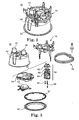
- humidification chamber 16 includes a housing 40 coupled to a base plate 42. Positioned between housing 40 and base plate 42 is a gasket 44, which is configured to provide a water tight seal between housing 40 and base plate 42. Housing 40 further includes a gas inlet 46 adapted for coupling to conduit 20 and a gas outlet 48 for coupling to conduit 22 and transmitting humidified gas to conduit 22. During operation, gas flows into chamber 16 from ventilator 12 through gas inlet 46. Humidifier 14 ( FIG. 1 ) provides heat to base plate 42, which evaporates liquid in chamber 16. From there, the gas within chamber 16 is humidified and transmitted to patient circuit 18 through gas outlet 48.
- a float valve system 50 is positioned within housing 40 to control an amount of fluid within the chamber 16.
- float valve system 50 includes a lower float 52, an upper float 54 and a valve assembly 56.
- Lower float 52 is coupled to valve assembly 56 through a first actuating member 58 whereas upper float 54 is coupled to valve assembly 56 through a second actuating member 60.
- First actuating member 58 and second actuating member 60 are spaced apart from one another in a horizontal direction.
- Lower float 52 cooperates with valve assembly 56 to prevent fluid from entering chamber 16 when a level of liquid in the chamber 16 reaches a first predetermined level.
- upper float 54 cooperates with valve assembly 56 to prevent fluid from entering chamber 16 when a level of liquid in the chamber 16 reaches a second predetermined level.
- lower float 52 and upper float 54 operate independently to selectively seal portions of valve assembly 56 such that further fluid is prevented from entering chamber 16.
- the second predetermined level is greater than the first predetermined level.
- the first predetermined level is greater than the second predetermined level.
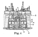
- Valve assembly 56 includes a retaining element 62, a support structure 64 and a diaphragm 66 positioned between the retaining element 62 and the support structure 64. Both lower float 52 and upper float 54 are pivotally coupled to support structure 64. Diaphragm 66 is formed of a flexible material (e.g., silicone) configured to seal against retaining element 62. As liquid within the housing 40 rises, lower float 52 urges actuating member 58 against diaphragm 66 and towards retaining element 62. Likewise, upper float 54 urges actuating member 60 against diaphragm 66 toward retaining element 62. As discussed in greater detail below, liquid enters housing 40 through tubing 70, which is fluidly coupled to retaining element 62. From retaining element 62, liquid flows into chamber 16 until lower float 52 or upper float 54 operates to prevent liquid from entering chamber 16.
- tubing 70 which is fluidly coupled to retaining element 62.
- a locking assembly 72 can be provided during shipment of the humidification chamber 16 so as to retain the tubing 70 as well as lower float 52 and upper float 54 against base plate 42.
- the locking assembly 72 can also protect debris and/or other contaminants from entering chamber 16 through gas inlet 46 and/or gas outlet 48. The locking assembly 72 is removed from chamber 16 and disposed prior to operation of the chamber 16.
- Path 78 includes a first vertical segment 79, wherein water enters housing 40 through a water inlet 80 coupled to tubing 70.
- Inlet 80 is fluidly coupled to retaining element 62, which transfers water to a valve conduit 82 between a lower portion of retaining element 62 and an upper portion of diaphragm 66.
- a valve seat 84 is positioned between retaining element 62 and valve conduit 82.
- Lower float 52 can be positioned so as to seal valve seat 84 upon fluid in chamber 16 reaching a first predetermined level. If valve seat 84 remains open, fluid then passes through valve conduit 82 to a second valve seat 86 through a second, horizontal segment 87 of path 78. Second segment 87 transfers fluid in a direction that is different (e.g., perpendicular) than the direction of first segment 79.
- actuating rod 60 is configured to urge diaphragm 66 against valve seat 86 to prevent further liquid from flowing into chamber 16.
- Path 78 further includes a third, vertical segment 89, transferring fluid from conduit 82 through valve seat 86.
- Third segment 89 is in a substantially opposite direction from first segment 79.
- valve seat 84 and valve seat 86 are substantially the same size. After passing through valve seat 86, liquid ultimately enters chamber 16.
- fluid path 78 is substantially "U" shaped, transferring fluid entering inlet 80 to chamber 16 so as to provide small sealing areas for valve seats 84 and 86, thereby reducing the risk of leaks occurring in valve assembly 56.
- float valve system 50 through use of both lower float 52 and upper float 54, provides a redundant safety mechanism to prevent a fluid level within chamber 16 from rising too high.
- another component can be utilized to prevent further fluid from entering the chamber 16. For example, if one of the floats 52, 54 fail, the other float will operate to prevent fluid from entering the chamber.
Landscapes
- Health & Medical Sciences (AREA)
- Life Sciences & Earth Sciences (AREA)
- General Health & Medical Sciences (AREA)
- Engineering & Computer Science (AREA)
- Anesthesiology (AREA)
- Biomedical Technology (AREA)
- Heart & Thoracic Surgery (AREA)
- Pulmonology (AREA)
- Hematology (AREA)
- Animal Behavior & Ethology (AREA)
- Emergency Medicine (AREA)
- Public Health (AREA)
- Veterinary Medicine (AREA)
- Air Humidification (AREA)
- Respiratory Apparatuses And Protective Means (AREA)
- Float Valves (AREA)
- Control Of Non-Electrical Variables (AREA)
Priority Applications (1)
| Application Number | Priority Date | Filing Date | Title |
|---|---|---|---|
| EP15198024.0A EP3028731A1 (en) | 2009-11-11 | 2010-10-12 | Float valve system for a respiratory humidification system |
Applications Claiming Priority (2)
| Application Number | Priority Date | Filing Date | Title |
|---|---|---|---|
| US12/616,414 US8347909B2 (en) | 2009-11-11 | 2009-11-11 | Float valve system for a respiratory humidification system |
| PCT/US2010/052342 WO2011059623A1 (en) | 2009-11-11 | 2010-10-12 | Float valve system for a respiratory humidification system |
Related Child Applications (2)
| Application Number | Title | Priority Date | Filing Date |
|---|---|---|---|
| EP15198024.0A Division EP3028731A1 (en) | 2009-11-11 | 2010-10-12 | Float valve system for a respiratory humidification system |
| EP15198024.0A Division-Into EP3028731A1 (en) | 2009-11-11 | 2010-10-12 | Float valve system for a respiratory humidification system |
Publications (2)
| Publication Number | Publication Date |
|---|---|
| EP2498856A1 EP2498856A1 (en) | 2012-09-19 |
| EP2498856B1 true EP2498856B1 (en) | 2016-03-02 |
Family
ID=43332567
Family Applications (2)
| Application Number | Title | Priority Date | Filing Date |
|---|---|---|---|
| EP10768663.6A Active EP2498856B1 (en) | 2009-11-11 | 2010-10-12 | Float valve system for a respiratory humidification system |
| EP15198024.0A Withdrawn EP3028731A1 (en) | 2009-11-11 | 2010-10-12 | Float valve system for a respiratory humidification system |
Family Applications After (1)
| Application Number | Title | Priority Date | Filing Date |
|---|---|---|---|
| EP15198024.0A Withdrawn EP3028731A1 (en) | 2009-11-11 | 2010-10-12 | Float valve system for a respiratory humidification system |
Country Status (11)
| Country | Link |
|---|---|
| US (1) | US8347909B2 (enExample) |
| EP (2) | EP2498856B1 (enExample) |
| JP (2) | JP5763089B2 (enExample) |
| CN (2) | CN103096962B (enExample) |
| AU (1) | AU2010318561B2 (enExample) |
| BR (1) | BR112012011254B1 (enExample) |
| CA (1) | CA2780519C (enExample) |
| ES (1) | ES2568216T3 (enExample) |
| MX (2) | MX348424B (enExample) |
| RU (1) | RU2579628C2 (enExample) |
| WO (1) | WO2011059623A1 (enExample) |
Families Citing this family (18)
| Publication number | Priority date | Publication date | Assignee | Title |
|---|---|---|---|---|
| ITMO20060202A1 (it) * | 2006-06-21 | 2007-12-22 | Galliano Bentivoglio | Pistola per erogare combustibile liquido |
| US8347909B2 (en) * | 2009-11-11 | 2013-01-08 | Carefusion 2200, Inc. | Float valve system for a respiratory humidification system |
| CN105307715B (zh) | 2012-03-15 | 2017-11-17 | 费雪派克医疗保健有限公司 | 呼吸气体加湿系统 |
| CN107335122B (zh) * | 2012-04-27 | 2022-02-18 | 费雪派克医疗保健有限公司 | 用于呼吸增湿系统的可用性特征 |
| EP4223348B1 (en) | 2012-06-25 | 2025-02-19 | Fisher & Paykel Healthcare Limited | Humidification chamber with microstructures |
| GB2527226B (en) * | 2013-03-14 | 2020-05-13 | Fisher & Paykel Healthcare Ltd | Medical components with microstructures for humidification and condensate management |
| US10207074B2 (en) * | 2013-09-04 | 2019-02-19 | Fisher & Paykel Healthcare Limited | Float retention arrangement for humidification chamber |
| DE112014004197T5 (de) | 2013-09-13 | 2016-06-02 | Fisher & Paykel Healthcare Limited | Verbindungen für Befeuchtungssystem |
| WO2015119515A1 (en) | 2014-02-07 | 2015-08-13 | Fisher & Paykel Healthcare Limited | Respiratory humidification system |
| EP3607988B1 (en) | 2014-06-03 | 2025-09-10 | Fisher & Paykel Healthcare Limited | A humidification chamber for a respiratory therapy apparatus |
| JP7291482B2 (ja) * | 2016-05-02 | 2023-06-15 | フィッシャー アンド ペイケル ヘルスケア リミテッド | 呼吸補助装置用の加湿チャンバおよびチャンバシール |
| TWI657841B (zh) * | 2017-08-10 | 2019-05-01 | 貝斯美德股份有限公司 | 具有懸吊式浮子的加濕室 |
| CN108253572B (zh) * | 2018-02-07 | 2023-07-04 | 佛山市金星徽电器有限公司 | 一种具有双阀体结构的加湿器 |
| US11338105B2 (en) * | 2018-03-27 | 2022-05-24 | Globalmed, Inc. | Respiratory humidification device |
| US11464936B2 (en) * | 2019-04-25 | 2022-10-11 | Besmed Health Business Corp. | Auto feed humidification chamber with improved structure |
| CN111888612B (zh) * | 2019-05-06 | 2022-10-28 | 宁波贝斯美德医用器械有限公司 | 自动注水加湿室结构改良 |
| CN111888610B (zh) * | 2020-07-27 | 2024-09-27 | 绵竹市人民医院 | 一种呼吸机集水杯及呼吸机 |
| CN114060724B (zh) * | 2020-08-07 | 2025-05-30 | 广州市创韦电子科技有限公司 | 供液系统 |
Family Cites Families (29)
| Publication number | Priority date | Publication date | Assignee | Title |
|---|---|---|---|---|
| US4529867A (en) | 1984-02-09 | 1985-07-16 | Inspiron Corporation | Humidifier and heater |
| CN87205154U (zh) * | 1987-09-02 | 1988-06-29 | 邓长春 | 气压式液体开关阀 |
| NZ221689A (en) * | 1987-09-07 | 1990-09-26 | Fisher & Paykel | Humidifier: float in gas chamber controls water inlet |
| ES2052023T3 (es) | 1989-10-11 | 1994-07-01 | Zip Heaters Aust Pty Ltd | Camara de flotacion. |
| USRE35153E (en) * | 1990-04-17 | 1996-02-06 | Duracraft Corporation | Humidifier with float activated water level responsive turn off |
| JP3433397B2 (ja) | 1992-09-23 | 2003-08-04 | フィッシャー アンド ペイケル アプライアンシーズ リミテッド | フロート弁装置及び呼吸用加湿器 |
| US5669083A (en) * | 1995-03-24 | 1997-09-23 | Leombruni, Sr.; Roland J. | Water saver for flush tanks |
| US6129110A (en) * | 1996-04-17 | 2000-10-10 | Milton Roy Company | Fluid level management system |
| GB2329451B (en) | 1997-09-23 | 2002-01-02 | Spirax Sarco Ltd | Float operated devices |
| US5945038A (en) * | 1998-08-07 | 1999-08-31 | Bemis Manufacturing Company | Humidifier wick assembly with float rod retainer |
| US6450196B1 (en) * | 2000-08-07 | 2002-09-17 | Gaap Gas Controls Llc | Float valve |
| US6427984B1 (en) * | 2000-08-11 | 2002-08-06 | Hamilton Beach/Proctor-Silex, Inc. | Evaporative humidifier |
| US6564820B2 (en) | 2001-10-09 | 2003-05-20 | United Technologies Corporation | Gas flow stop device |
| GB0212375D0 (en) * | 2002-05-29 | 2002-07-10 | Intersurgical Ltd | Improvements relating to floats |
| WO2004015315A1 (en) * | 2002-07-31 | 2004-02-19 | Dynamic Fluid Control (Pty) Ltd | Vent valve |
| US20040020998A1 (en) * | 2002-08-01 | 2004-02-05 | Helmut Stueble | Fog generator |
| US7306205B2 (en) * | 2002-08-30 | 2007-12-11 | Fisher & Paykel Healthcare Limited | Humidification system |
| US6988497B2 (en) * | 2002-09-18 | 2006-01-24 | Medex Cardio-Pulmonary, Inc. | Apparatus for equalizing air pressure in air respiratory system |
| US6745800B1 (en) * | 2003-09-04 | 2004-06-08 | Datex-Ohmeda, Inc. | Arrangement for preventing overfill of anesthetic liquid |
| US7182321B2 (en) * | 2004-12-02 | 2007-02-27 | Chuan-Pan Huang | Safety device for a humidifier |
| US8997740B2 (en) * | 2005-09-27 | 2015-04-07 | Ric Investments, Llc | Humidifier with back-flow prevention valve |
| US8701662B2 (en) * | 2005-09-27 | 2014-04-22 | Ric Investments, Llc | Humidifier with back-flow prevention valve |
| US7614420B2 (en) | 2006-04-17 | 2009-11-10 | Allegiance Corporation | Autofeed mechanism for heated humidifier chamber |
| GB0615872D0 (en) * | 2006-08-10 | 2006-09-27 | Intersurgical Ag | Improvements relating to humidification chambers |
| GB0615871D0 (en) | 2006-08-10 | 2006-09-20 | Intersurgical Ag | Improvements relating to humidification chambers |
| US7722016B2 (en) * | 2006-08-31 | 2010-05-25 | Medex Cardio-Pulmonary, Inc. | Float for humidification chamber |
| KR101138555B1 (ko) * | 2007-10-23 | 2012-05-11 | 웅진코웨이주식회사 | 수위조절장치 |
| EP2119466A1 (en) * | 2008-05-12 | 2009-11-18 | Deas S.R.L. | Humidifier with safety elements |
| US8347909B2 (en) * | 2009-11-11 | 2013-01-08 | Carefusion 2200, Inc. | Float valve system for a respiratory humidification system |
-
2009
- 2009-11-11 US US12/616,414 patent/US8347909B2/en active Active
-
2010
- 2010-10-12 CA CA2780519A patent/CA2780519C/en active Active
- 2010-10-12 ES ES10768663.6T patent/ES2568216T3/es active Active
- 2010-10-12 MX MX2014010529A patent/MX348424B/es unknown
- 2010-10-12 EP EP10768663.6A patent/EP2498856B1/en active Active
- 2010-10-12 CN CN201080051468.3A patent/CN103096962B/zh active Active
- 2010-10-12 JP JP2012538825A patent/JP5763089B2/ja active Active
- 2010-10-12 AU AU2010318561A patent/AU2010318561B2/en active Active
- 2010-10-12 WO PCT/US2010/052342 patent/WO2011059623A1/en not_active Ceased
- 2010-10-12 BR BR112012011254A patent/BR112012011254B1/pt active IP Right Grant
- 2010-10-12 CN CN201510667576.8A patent/CN105288815B/zh active Active
- 2010-10-12 EP EP15198024.0A patent/EP3028731A1/en not_active Withdrawn
- 2010-10-12 RU RU2012124055/14A patent/RU2579628C2/ru not_active IP Right Cessation
- 2010-10-12 MX MX2012005486A patent/MX2012005486A/es active IP Right Grant
-
2015
- 2015-06-10 JP JP2015117260A patent/JP6007290B2/ja not_active Expired - Fee Related
Also Published As
| Publication number | Publication date |
|---|---|
| BR112012011254A2 (pt) | 2016-04-05 |
| CN103096962A (zh) | 2013-05-08 |
| JP2015211851A (ja) | 2015-11-26 |
| AU2010318561B2 (en) | 2015-07-02 |
| US8347909B2 (en) | 2013-01-08 |
| EP3028731A1 (en) | 2016-06-08 |
| CN103096962B (zh) | 2015-11-25 |
| MX348424B (es) | 2017-06-12 |
| BR112012011254B1 (pt) | 2019-12-24 |
| RU2012124055A (ru) | 2013-12-20 |
| CN105288815A (zh) | 2016-02-03 |
| JP5763089B2 (ja) | 2015-08-12 |
| EP2498856A1 (en) | 2012-09-19 |
| CA2780519A1 (en) | 2011-05-19 |
| CA2780519C (en) | 2017-11-07 |
| US20110108028A1 (en) | 2011-05-12 |
| CN105288815B (zh) | 2018-03-30 |
| WO2011059623A1 (en) | 2011-05-19 |
| AU2010318561A1 (en) | 2012-06-28 |
| ES2568216T3 (es) | 2016-04-28 |
| JP2013517010A (ja) | 2013-05-16 |
| MX2012005486A (es) | 2012-08-01 |
| JP6007290B2 (ja) | 2016-10-12 |
| RU2579628C2 (ru) | 2016-04-10 |
Similar Documents
| Publication | Publication Date | Title |
|---|---|---|
| EP2498856B1 (en) | Float valve system for a respiratory humidification system | |
| JP2013517010A5 (enExample) | ||
| US8573208B2 (en) | Exhaust assembly | |
| EP0589429B1 (en) | Humidifier with dual float valves | |
| US20210376706A1 (en) | Breathing assistance device with linear actuated gas regulating valve | |
| JP5054696B2 (ja) | 逆流防止弁付加湿器 | |
| US20050166915A1 (en) | Disposable active humidifier for the mechanical ventilation of a patient | |
| EP3033131B1 (en) | Fluid coupling member including valve member | |
| WO2010138268A1 (en) | Systems and methods for protecting components of a breathing assistance system | |
| KR20100052530A (ko) | 호흡 가스 전달과 공유 시스템 및 방법 | |
| US9498657B2 (en) | Diaphragm | |
| JP2006239424A (ja) | 圧力逃がし弁 | |
| AU2015227520B2 (en) | Float valve system for a respiratory humidification system | |
| CN121221894A (zh) | 睡眠呼吸机以及防倒灌方法 |
Legal Events
| Date | Code | Title | Description |
|---|---|---|---|
| PUAI | Public reference made under article 153(3) epc to a published international application that has entered the european phase |
Free format text: ORIGINAL CODE: 0009012 |
|
| 17P | Request for examination filed |
Effective date: 20120611 |
|
| AK | Designated contracting states |
Kind code of ref document: A1 Designated state(s): AL AT BE BG CH CY CZ DE DK EE ES FI FR GB GR HR HU IE IS IT LI LT LU LV MC MK MT NL NO PL PT RO RS SE SI SK SM TR |
|
| DAX | Request for extension of the european patent (deleted) | ||
| 17Q | First examination report despatched |
Effective date: 20141111 |
|
| GRAP | Despatch of communication of intention to grant a patent |
Free format text: ORIGINAL CODE: EPIDOSNIGR1 |
|
| INTG | Intention to grant announced |
Effective date: 20150915 |
|
| GRAS | Grant fee paid |
Free format text: ORIGINAL CODE: EPIDOSNIGR3 |
|
| GRAA | (expected) grant |
Free format text: ORIGINAL CODE: 0009210 |
|
| AK | Designated contracting states |
Kind code of ref document: B1 Designated state(s): AL AT BE BG CH CY CZ DE DK EE ES FI FR GB GR HR HU IE IS IT LI LT LU LV MC MK MT NL NO PL PT RO RS SE SI SK SM TR |
|
| REG | Reference to a national code |
Ref country code: GB Ref legal event code: FG4D |
|
| REG | Reference to a national code |
Ref country code: AT Ref legal event code: REF Ref document number: 777564 Country of ref document: AT Kind code of ref document: T Effective date: 20160315 Ref country code: CH Ref legal event code: EP |
|
| REG | Reference to a national code |
Ref country code: IE Ref legal event code: FG4D |
|
| REG | Reference to a national code |
Ref country code: DE Ref legal event code: R096 Ref document number: 602010030921 Country of ref document: DE |
|
| REG | Reference to a national code |
Ref country code: ES Ref legal event code: FG2A Ref document number: 2568216 Country of ref document: ES Kind code of ref document: T3 Effective date: 20160428 |
|
| REG | Reference to a national code |
Ref country code: NL Ref legal event code: MP Effective date: 20160302 |
|
| REG | Reference to a national code |
Ref country code: LT Ref legal event code: MG4D |
|
| REG | Reference to a national code |
Ref country code: AT Ref legal event code: MK05 Ref document number: 777564 Country of ref document: AT Kind code of ref document: T Effective date: 20160302 |
|
| PG25 | Lapsed in a contracting state [announced via postgrant information from national office to epo] |
Ref country code: FI Free format text: LAPSE BECAUSE OF FAILURE TO SUBMIT A TRANSLATION OF THE DESCRIPTION OR TO PAY THE FEE WITHIN THE PRESCRIBED TIME-LIMIT Effective date: 20160302 Ref country code: HR Free format text: LAPSE BECAUSE OF FAILURE TO SUBMIT A TRANSLATION OF THE DESCRIPTION OR TO PAY THE FEE WITHIN THE PRESCRIBED TIME-LIMIT Effective date: 20160302 Ref country code: NO Free format text: LAPSE BECAUSE OF FAILURE TO SUBMIT A TRANSLATION OF THE DESCRIPTION OR TO PAY THE FEE WITHIN THE PRESCRIBED TIME-LIMIT Effective date: 20160602 Ref country code: GR Free format text: LAPSE BECAUSE OF FAILURE TO SUBMIT A TRANSLATION OF THE DESCRIPTION OR TO PAY THE FEE WITHIN THE PRESCRIBED TIME-LIMIT Effective date: 20160603 |
|
| PG25 | Lapsed in a contracting state [announced via postgrant information from national office to epo] |
Ref country code: SE Free format text: LAPSE BECAUSE OF FAILURE TO SUBMIT A TRANSLATION OF THE DESCRIPTION OR TO PAY THE FEE WITHIN THE PRESCRIBED TIME-LIMIT Effective date: 20160302 Ref country code: PL Free format text: LAPSE BECAUSE OF FAILURE TO SUBMIT A TRANSLATION OF THE DESCRIPTION OR TO PAY THE FEE WITHIN THE PRESCRIBED TIME-LIMIT Effective date: 20160302 Ref country code: LT Free format text: LAPSE BECAUSE OF FAILURE TO SUBMIT A TRANSLATION OF THE DESCRIPTION OR TO PAY THE FEE WITHIN THE PRESCRIBED TIME-LIMIT Effective date: 20160302 Ref country code: AT Free format text: LAPSE BECAUSE OF FAILURE TO SUBMIT A TRANSLATION OF THE DESCRIPTION OR TO PAY THE FEE WITHIN THE PRESCRIBED TIME-LIMIT Effective date: 20160302 Ref country code: NL Free format text: LAPSE BECAUSE OF FAILURE TO SUBMIT A TRANSLATION OF THE DESCRIPTION OR TO PAY THE FEE WITHIN THE PRESCRIBED TIME-LIMIT Effective date: 20160302 Ref country code: LV Free format text: LAPSE BECAUSE OF FAILURE TO SUBMIT A TRANSLATION OF THE DESCRIPTION OR TO PAY THE FEE WITHIN THE PRESCRIBED TIME-LIMIT Effective date: 20160302 Ref country code: RS Free format text: LAPSE BECAUSE OF FAILURE TO SUBMIT A TRANSLATION OF THE DESCRIPTION OR TO PAY THE FEE WITHIN THE PRESCRIBED TIME-LIMIT Effective date: 20160302 |
|
| REG | Reference to a national code |
Ref country code: FR Ref legal event code: PLFP Year of fee payment: 7 |
|
| PG25 | Lapsed in a contracting state [announced via postgrant information from national office to epo] |
Ref country code: EE Free format text: LAPSE BECAUSE OF FAILURE TO SUBMIT A TRANSLATION OF THE DESCRIPTION OR TO PAY THE FEE WITHIN THE PRESCRIBED TIME-LIMIT Effective date: 20160302 Ref country code: IS Free format text: LAPSE BECAUSE OF FAILURE TO SUBMIT A TRANSLATION OF THE DESCRIPTION OR TO PAY THE FEE WITHIN THE PRESCRIBED TIME-LIMIT Effective date: 20160702 |
|
| PG25 | Lapsed in a contracting state [announced via postgrant information from national office to epo] |
Ref country code: SM Free format text: LAPSE BECAUSE OF FAILURE TO SUBMIT A TRANSLATION OF THE DESCRIPTION OR TO PAY THE FEE WITHIN THE PRESCRIBED TIME-LIMIT Effective date: 20160302 Ref country code: PT Free format text: LAPSE BECAUSE OF FAILURE TO SUBMIT A TRANSLATION OF THE DESCRIPTION OR TO PAY THE FEE WITHIN THE PRESCRIBED TIME-LIMIT Effective date: 20160704 Ref country code: RO Free format text: LAPSE BECAUSE OF FAILURE TO SUBMIT A TRANSLATION OF THE DESCRIPTION OR TO PAY THE FEE WITHIN THE PRESCRIBED TIME-LIMIT Effective date: 20160302 Ref country code: SK Free format text: LAPSE BECAUSE OF FAILURE TO SUBMIT A TRANSLATION OF THE DESCRIPTION OR TO PAY THE FEE WITHIN THE PRESCRIBED TIME-LIMIT Effective date: 20160302 Ref country code: CZ Free format text: LAPSE BECAUSE OF FAILURE TO SUBMIT A TRANSLATION OF THE DESCRIPTION OR TO PAY THE FEE WITHIN THE PRESCRIBED TIME-LIMIT Effective date: 20160302 |
|
| REG | Reference to a national code |
Ref country code: DE Ref legal event code: R097 Ref document number: 602010030921 Country of ref document: DE |
|
| PG25 | Lapsed in a contracting state [announced via postgrant information from national office to epo] |
Ref country code: BE Free format text: LAPSE BECAUSE OF FAILURE TO SUBMIT A TRANSLATION OF THE DESCRIPTION OR TO PAY THE FEE WITHIN THE PRESCRIBED TIME-LIMIT Effective date: 20160302 |
|
| PLBE | No opposition filed within time limit |
Free format text: ORIGINAL CODE: 0009261 |
|
| STAA | Information on the status of an ep patent application or granted ep patent |
Free format text: STATUS: NO OPPOSITION FILED WITHIN TIME LIMIT |
|
| PG25 | Lapsed in a contracting state [announced via postgrant information from national office to epo] |
Ref country code: DK Free format text: LAPSE BECAUSE OF FAILURE TO SUBMIT A TRANSLATION OF THE DESCRIPTION OR TO PAY THE FEE WITHIN THE PRESCRIBED TIME-LIMIT Effective date: 20160302 |
|
| 26N | No opposition filed |
Effective date: 20161205 |
|
| PG25 | Lapsed in a contracting state [announced via postgrant information from national office to epo] |
Ref country code: BG Free format text: LAPSE BECAUSE OF FAILURE TO SUBMIT A TRANSLATION OF THE DESCRIPTION OR TO PAY THE FEE WITHIN THE PRESCRIBED TIME-LIMIT Effective date: 20160602 Ref country code: SI Free format text: LAPSE BECAUSE OF FAILURE TO SUBMIT A TRANSLATION OF THE DESCRIPTION OR TO PAY THE FEE WITHIN THE PRESCRIBED TIME-LIMIT Effective date: 20160302 |
|
| REG | Reference to a national code |
Ref country code: DE Ref legal event code: R081 Ref document number: 602010030921 Country of ref document: DE Owner name: VYAIRE MEDICAL CONSUMABLES LLC (N.D.GES.D. STA, US Free format text: FORMER OWNER: CAREFUSION 2200, INC., SAN DIEGO, CALIF., US |
|
| REG | Reference to a national code |
Ref country code: CH Ref legal event code: PL |
|
| REG | Reference to a national code |
Ref country code: IE Ref legal event code: MM4A |
|
| PG25 | Lapsed in a contracting state [announced via postgrant information from national office to epo] |
Ref country code: LI Free format text: LAPSE BECAUSE OF NON-PAYMENT OF DUE FEES Effective date: 20161031 Ref country code: CH Free format text: LAPSE BECAUSE OF NON-PAYMENT OF DUE FEES Effective date: 20161031 |
|
| PG25 | Lapsed in a contracting state [announced via postgrant information from national office to epo] |
Ref country code: LU Free format text: LAPSE BECAUSE OF NON-PAYMENT OF DUE FEES Effective date: 20161012 |
|
| REG | Reference to a national code |
Ref country code: FR Ref legal event code: PLFP Year of fee payment: 8 |
|
| REG | Reference to a national code |
Ref country code: FR Ref legal event code: CD Owner name: VYAIRE MEDICAL CONSUMABLES LLC, US Effective date: 20171010 Ref country code: FR Ref legal event code: TP Owner name: VYAIRE MEDICAL CONSUMABLES LLC, US Effective date: 20171010 |
|
| PG25 | Lapsed in a contracting state [announced via postgrant information from national office to epo] |
Ref country code: IE Free format text: LAPSE BECAUSE OF NON-PAYMENT OF DUE FEES Effective date: 20161012 |
|
| PG25 | Lapsed in a contracting state [announced via postgrant information from national office to epo] |
Ref country code: HU Free format text: LAPSE BECAUSE OF FAILURE TO SUBMIT A TRANSLATION OF THE DESCRIPTION OR TO PAY THE FEE WITHIN THE PRESCRIBED TIME-LIMIT; INVALID AB INITIO Effective date: 20101012 Ref country code: CY Free format text: LAPSE BECAUSE OF FAILURE TO SUBMIT A TRANSLATION OF THE DESCRIPTION OR TO PAY THE FEE WITHIN THE PRESCRIBED TIME-LIMIT Effective date: 20160302 |
|
| PG25 | Lapsed in a contracting state [announced via postgrant information from national office to epo] |
Ref country code: MK Free format text: LAPSE BECAUSE OF FAILURE TO SUBMIT A TRANSLATION OF THE DESCRIPTION OR TO PAY THE FEE WITHIN THE PRESCRIBED TIME-LIMIT Effective date: 20160302 Ref country code: TR Free format text: LAPSE BECAUSE OF FAILURE TO SUBMIT A TRANSLATION OF THE DESCRIPTION OR TO PAY THE FEE WITHIN THE PRESCRIBED TIME-LIMIT Effective date: 20160302 Ref country code: MT Free format text: LAPSE BECAUSE OF NON-PAYMENT OF DUE FEES Effective date: 20161031 Ref country code: MC Free format text: LAPSE BECAUSE OF FAILURE TO SUBMIT A TRANSLATION OF THE DESCRIPTION OR TO PAY THE FEE WITHIN THE PRESCRIBED TIME-LIMIT Effective date: 20160302 |
|
| REG | Reference to a national code |
Ref country code: FR Ref legal event code: PLFP Year of fee payment: 9 |
|
| PG25 | Lapsed in a contracting state [announced via postgrant information from national office to epo] |
Ref country code: AL Free format text: LAPSE BECAUSE OF FAILURE TO SUBMIT A TRANSLATION OF THE DESCRIPTION OR TO PAY THE FEE WITHIN THE PRESCRIBED TIME-LIMIT Effective date: 20160302 |
|
| REG | Reference to a national code |
Ref country code: ES Ref legal event code: PC2A Owner name: VYAIRE MEDICAL CONSUMABLES LLC. Effective date: 20201027 |
|
| P01 | Opt-out of the competence of the unified patent court (upc) registered |
Effective date: 20230525 |
|
| PGFP | Annual fee paid to national office [announced via postgrant information from national office to epo] |
Ref country code: DE Payment date: 20240919 Year of fee payment: 15 |
|
| PGFP | Annual fee paid to national office [announced via postgrant information from national office to epo] |
Ref country code: ES Payment date: 20241104 Year of fee payment: 15 |
|
| REG | Reference to a national code |
Ref country code: GB Ref legal event code: 732E Free format text: REGISTERED BETWEEN 20250320 AND 20250326 |
|
| REG | Reference to a national code |
Ref country code: DE Ref legal event code: R081 Ref document number: 602010030921 Country of ref document: DE Owner name: SUNMED GROUP HOLDINGS, LLC (N. D. GES. DES STA, US Free format text: FORMER OWNER: VYAIRE MEDICAL CONSUMABLES LLC (N.D.GES.D. STAATES DELAWARE), FRANKLIN LAKES, N.J., US |
|
| PGFP | Annual fee paid to national office [announced via postgrant information from national office to epo] |
Ref country code: IT Payment date: 20250923 Year of fee payment: 16 |
|
| PGFP | Annual fee paid to national office [announced via postgrant information from national office to epo] |
Ref country code: GB Payment date: 20250923 Year of fee payment: 16 |
|
| PGFP | Annual fee paid to national office [announced via postgrant information from national office to epo] |
Ref country code: FR Payment date: 20250924 Year of fee payment: 16 |