EP2498586A2 - Flexible Flat Cable and Image Display Device - Google Patents
Flexible Flat Cable and Image Display Device Download PDFInfo
- Publication number
- EP2498586A2 EP2498586A2 EP12158691A EP12158691A EP2498586A2 EP 2498586 A2 EP2498586 A2 EP 2498586A2 EP 12158691 A EP12158691 A EP 12158691A EP 12158691 A EP12158691 A EP 12158691A EP 2498586 A2 EP2498586 A2 EP 2498586A2
- Authority
- EP
- European Patent Office
- Prior art keywords
- end portions
- main body
- flexible flat
- cable main
- flat cable
- Prior art date
- Legal status (The legal status is an assumption and is not a legal conclusion. Google has not performed a legal analysis and makes no representation as to the accuracy of the status listed.)
- Withdrawn
Links
- 239000011347 resin Substances 0.000 claims abstract description 44
- 229920005989 resin Polymers 0.000 claims abstract description 44
- 230000003014 reinforcing effect Effects 0.000 claims abstract description 39
- 239000004020 conductor Substances 0.000 claims abstract description 28
- 238000005452 bending Methods 0.000 claims abstract description 16
- 230000001154 acute effect Effects 0.000 claims abstract description 13
- 230000008878 coupling Effects 0.000 claims description 3
- 238000010168 coupling process Methods 0.000 claims description 3
- 238000005859 coupling reaction Methods 0.000 claims description 3
- 239000012777 electrically insulating material Substances 0.000 claims description 3
- 239000004973 liquid crystal related substance Substances 0.000 description 14
- 239000000853 adhesive Substances 0.000 description 4
- 230000002411 adverse Effects 0.000 description 3
- 238000003780 insertion Methods 0.000 description 3
- 230000037431 insertion Effects 0.000 description 3
- 239000000463 material Substances 0.000 description 3
- 230000035945 sensitivity Effects 0.000 description 3
- 230000015556 catabolic process Effects 0.000 description 2
- 238000006731 degradation reaction Methods 0.000 description 2
- 230000003647 oxidation Effects 0.000 description 2
- 238000007254 oxidation reaction Methods 0.000 description 2
- RYGMFSIKBFXOCR-UHFFFAOYSA-N Copper Chemical compound [Cu] RYGMFSIKBFXOCR-UHFFFAOYSA-N 0.000 description 1
- ATJFFYVFTNAWJD-UHFFFAOYSA-N Tin Chemical compound [Sn] ATJFFYVFTNAWJD-UHFFFAOYSA-N 0.000 description 1
- 239000011889 copper foil Substances 0.000 description 1
- 230000009977 dual effect Effects 0.000 description 1
- 230000002349 favourable effect Effects 0.000 description 1
- 238000009434 installation Methods 0.000 description 1
- 238000012986 modification Methods 0.000 description 1
- 230000004048 modification Effects 0.000 description 1
- 229920000728 polyester Polymers 0.000 description 1
- 229920006267 polyester film Polymers 0.000 description 1
- 229920000098 polyolefin Polymers 0.000 description 1
Images


Classifications
-
- H—ELECTRICITY
- H05—ELECTRIC TECHNIQUES NOT OTHERWISE PROVIDED FOR
- H05K—PRINTED CIRCUITS; CASINGS OR CONSTRUCTIONAL DETAILS OF ELECTRIC APPARATUS; MANUFACTURE OF ASSEMBLAGES OF ELECTRICAL COMPONENTS
- H05K1/00—Printed circuits
- H05K1/02—Details
- H05K1/11—Printed elements for providing electric connections to or between printed circuits
- H05K1/118—Printed elements for providing electric connections to or between printed circuits specially for flexible printed circuits, e.g. using folded portions
-
- H—ELECTRICITY
- H05—ELECTRIC TECHNIQUES NOT OTHERWISE PROVIDED FOR
- H05K—PRINTED CIRCUITS; CASINGS OR CONSTRUCTIONAL DETAILS OF ELECTRIC APPARATUS; MANUFACTURE OF ASSEMBLAGES OF ELECTRICAL COMPONENTS
- H05K1/00—Printed circuits
- H05K1/02—Details
- H05K1/0277—Bendability or stretchability details
- H05K1/028—Bending or folding regions of flexible printed circuits
- H05K1/0281—Reinforcement details thereof
-
- H—ELECTRICITY
- H05—ELECTRIC TECHNIQUES NOT OTHERWISE PROVIDED FOR
- H05K—PRINTED CIRCUITS; CASINGS OR CONSTRUCTIONAL DETAILS OF ELECTRIC APPARATUS; MANUFACTURE OF ASSEMBLAGES OF ELECTRICAL COMPONENTS
- H05K1/00—Printed circuits
- H05K1/02—Details
- H05K1/14—Structural association of two or more printed circuits
- H05K1/147—Structural association of two or more printed circuits at least one of the printed circuits being bent or folded, e.g. by using a flexible printed circuit
-
- H—ELECTRICITY
- H05—ELECTRIC TECHNIQUES NOT OTHERWISE PROVIDED FOR
- H05K—PRINTED CIRCUITS; CASINGS OR CONSTRUCTIONAL DETAILS OF ELECTRIC APPARATUS; MANUFACTURE OF ASSEMBLAGES OF ELECTRICAL COMPONENTS
- H05K2201/00—Indexing scheme relating to printed circuits covered by H05K1/00
- H05K2201/10—Details of components or other objects attached to or integrated in a printed circuit board
- H05K2201/10007—Types of components
- H05K2201/10189—Non-printed connector
-
- H—ELECTRICITY
- H05—ELECTRIC TECHNIQUES NOT OTHERWISE PROVIDED FOR
- H05K—PRINTED CIRCUITS; CASINGS OR CONSTRUCTIONAL DETAILS OF ELECTRIC APPARATUS; MANUFACTURE OF ASSEMBLAGES OF ELECTRICAL COMPONENTS
- H05K2201/00—Indexing scheme relating to printed circuits covered by H05K1/00
- H05K2201/20—Details of printed circuits not provided for in H05K2201/01 - H05K2201/10
- H05K2201/2009—Reinforced areas, e.g. for a specific part of a flexible printed circuit
Definitions
- the present invention generally relates to a flexible flat cable. More specifically, the preset invention relates to a flexible flat cable which electrically connects printed wiring boards. Furthermore, the present invention also relates to an image display device in which the flexible flat cable is provided.
- a conventional flexible flat cable for electrically connecting adjacent printed wiring boards includes a plurality of aligned, linear conductors and electrically insulating upper and lower resin films that cover the linear conductors. Terminals are formed by exposing both ends of the linear conductors at cut-outs at both ends of one of the resin films. Reinforcing plates are affixed over the resin film at both ends.
- the conventional flexible flat cable is used to electrically connect the adjacent printed wiring boards together by inserting the ends of the flexible flat cable (i.e., two ends where the terminals are formed and the reinforcing plates are affixed) from above into the connectors of the printed wiring boards.
- the flexible flat cable curves towards a shield plate that is disposed above the cable to block electromagnetic waves. This causes a problem that the flexible flat cable will touch the shield plate, which adversely affects electromagnetic interference (EMI) and electromagnetic sensitivity (EMS).
- EMI electromagnetic interference
- EMS electromagnetic sensitivity
- the former problem i.e., that of contacting with the shield plate
- widening the distance cannot be considered a favorable remedy because it is contrary to the need to reduce the thickness of the image display devices, such as liquid crystal television sets.
- One object of the present disclosure is to provide a flexible flat cable with which a middle portion of the flexible flat cable is prevented from contacting other parts of an image display device when the flexible flat cable is installed in the image display device.
- Another object of the present disclosure is to provide a flexible flat cable with which it is easier to install the flexible flat cable to the image display device and oil from fingertips is less likely to adhere to terminals of the flexible flat cable during installation.
- a flexible flat cable includes a cable main body and a pair of reinforcing plates.
- the cable main body includes a pair of resin films and a plurality of linear conductors.
- the lincar conductors are arranged in parallel to each other between the resin films.
- the linear conductors are exposed with respect to one of the resin films to form longitudinally extending electrical terminals of the flexible flat cable at end portions of the cable main body, respectively.
- Each of the reinforcing plates has a fixed end section.
- the fixed end sections are fixedly coupled to the end portions of the cable main body on the other of the resin films, respectively.
- the fixed end sections define a pair of bending lines such that the end portions of the cable main body are bendable relative to a middle portion of the cable main body that extends between the end portions of the cable main body to form acute corners between the end portions and the middle portion, respectively.
- FIG. 1 is a top plan view of a flexible flat cable in accordance with one embodiment, illustrating end portions of the flexible flat cable being bent relative to a middle portion of the flexible flat cable;
- FIG. 2 is a bottom plan view of the flexible flat cable illustrated in FIG. 1 ;
- FIG. 3 is a cross sectional view of the flexible flat cable taken along III-III line in FIG. 1 ;
- FIG. 4 is a cross sectional view of the flexible flat cable in accordance with one embodiment, illustrating the flexible flat cable before the end portions being bent relative to the main portion;
- FIG. 5 is a bottom plan view of the flexible flat cable illustrated in FIG. 4 , illustrating the flexible flat cable before the end portions being bent relative to the main portion;
- FIG. 6 is an enlarged cross sectional view of an image display device in which the flexible flat cable illustrated in FIG. 1 is installed, illustrating a connection between the flexible flat cable and printed wiring boards;
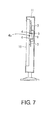
- FIG. 7 is a side elevational view of the image display device in which the flexible flat cable illustrated in FIG. 1 is installed, a cabinet of the image display device broken away to show internal configurations of the image display device.
- the image display device such as a flat-screen liquid crystal television set, mainly includes the flexible flat cable 1, main and sub printed wiring boards 3 (e.g., a plurality of printed wiring boards) with connectors 4, an electromagnetic shield plate 5, a liquid crystal module 10 (e.g., display module) and a cabinet 11.
- the flexible flat cable 1 electrically connects the printed wiring boards 3 to each other within the cabinet 11.
- the flexible flat cable I is electrically connected between the connectors 4 of the printed wiring boards 3.
- the liquid crystal module 10 displays an image.
- the liquid crystal module 10 is disposed within the cabinet 11 such that the liquid crystal module 10 faces a front opening of the cabinet 11.
- the liquid crystal module 10 mainly includes a backlight unit, a rear frame and a liquid crystal panel.
- the configuration of the liquid crystal module 10 is well known. Thus, the detailed description about the liquid crystal module 10 is omitted for the sake of brevity.
- the backlight unit is provided inside the rear frame.
- the liquid crystal panel is disposed on a front face side of the rear frame.
- the printed wiring boards 3 are attached adjacent to each other on convex components formed in a rear face of the rear frame of the liquid crystal module 10.
- the connectors 4 are disposed on the printed wiring boards 3 at mutually opposing positions of the printed wiring boards 3, respectively. As illustrated in FIG.
- the electromagnetic shield plate 5 disposed opposite the flexible flat cable 1.
- the electromagnetic shicld plate 5 covers the flexible flat cable 1.
- the electromagnetic shield plate 5 is attached to the printed wiring boards 3 spanning between the printed wiring boards 3. Specifically, the electromagnetic shield plate 5 is disposed rearward of the image display device relative to the printed wiring boards 3 such that the electromagnetic shield plate 5 covers the flexible flat cable 1 from a rear side of the image display device.
- the flexible flat cable 1 includes a cable main body and a pair of reinforcing plates 2.
- the cable main body mainly has a plurality of linear conductors 1 a and upper and lower resin films 1b and 1c.
- the linear conductors 1a are aligned in parallel to each other.
- the linear conductors 1a are disposed between the resin films 1b and 1c, and are covered with the resin films 1b and 1c.
- the resin films 1b and 1c are made of electrically insulating material.
- the lower resin film 1c (e.g., one of the resin films) has cut-out portions 1g at both lengthwise ends of the lower resin film 1c such that end portions of the linear conductors 1 a are exposed with respect to the lower resin film 1c through the cut-out portions 1g to form longitudinally extending electrical terminals 1d of the flexible flat cable 1.
- the linear conductors 1a are made of soft copper foil plated with tin.
- the linear conductors 1 a are formed as extremely thin wires.
- the linear conductors 1a are arranged in parallel rows at a specific pitch in a widthwise direction of the flexible flat cable 1.
- the resin films 1b and 1c cover the linear conductors 1a.
- the resin films 1b and 1c are polyester films, polyolefin films, or the like having a specific thickness.
- the resin films 1b and 1c are integrated by thermocompression bonding with the linear conductors 1 a in between.
- the flexible flat cable 1 further includes a pair of end portions 1e at both ends in a lengthwise direction of the flexible flat cable 1 and a middle portion 1h extending between the end portions 1e.
- the lengthwise direction is perpendicular to the widthwise direction.
- the end portions 1e are bendable relative to the middle portion 1h such that the end portions 1e and the middle portion 1h form acute corners 1i therebetween, respectively.
- the end portions 1e are bent at an acute angle relative to the middle portion 1h towards the lower resin film 1c to form bent ends.
- the end portions 1e are bent at bending positions P that are closer to a midst point of the flexible flat cable 1 in the lengthwise direction than the terminals 1d.
- the reinforcing plates 2 are affixed with an adhesive agent 1f on the upper resin film 1b at the end portions 1e.
- the reinforcing plates 2 serve to reinforce the end portions 1e of the flexible flat cable 1 such that the end portions 1e of the flexible flat cable 1 on which the terminals 1d are formed do not buckle when the end portions 1e are inserted into the connectors 4, respectively.
- the reinforcing plates 2 also serve as grips that are grasped by fingertips of a worker to make an insertion or removal work easier. As illustrated in FIG. 3 , the reinforcing plates 2 are longer than the end portions le in first directions D1 of the end portions 1e along which the linear conductors 1a extend at the end portions 1e, respectively.
- the reinforcing plates 2 have a first length L1 in the first directions D1 of the end portions 1e, respectively
- the end portions 1e have a second length L2 in the first directions D1 of the end portions 1e, respectively.
- the first length L1 of the reinforcing plates 2 is greater than the second length L2 of the end portions 1c.
- Each of the reinforcing plates 2 has a fixed end section 2a and a free end section 2b.
- the fixed end sections 2a are superposed over the upper resin film 1b at the end portions 1e, respectively.
- the fixed end sections 2a are affixed to the upper resin film 1b (e.g., the other of the resin films) at the end portions 1e with the adhesive agent 1f to reinforce the end portions 1e.
- the fixed end sections 2a are fixedly coupled to the end portions 1e, respectively, such that each of the fixed end sections 2a has an end edge that is aligned to an end edge of corresponding one of the end portions 1e.
- the free end sections 2b are arranged relative to the fixed end sections 2a, respectively.
- the free end sections 2b of the reinforcing plates 2 become grips that stick out from the end portions 1e beyond the bending positions P and the acute corners 1i, respectively.
- the free end sections 2b are free from directly coupling to the upper resin films 1b, respectively.
- the reinforcing plates 2 prefferably, to be made of polyester tape or the like with a strength having a thickness of about 0.2 to 0,3 mm.
- the reinforcing plates 2 are preferably about 2 to 5 mm longer than the end portions 1e (i.e., The first length L1 is about 2 to 5 mm longer than the second length L2), and are made from a material that is easy to grasp with fingertips.
- the reinforcing plates 2 are affixed to the upper resin film 1b of the flexible flat cable 1 to define a pair of transverse bending lines occurring at the bending positions P as seen in FIGS. 2 and 3 . Due to the properties of the materials of the linear conductors 1a and the resin films 1b and 1c, the flexible flat cable 1 has a predetermined bending radius such that the bending lines occur at the bending positions P, which are spaced from attachment area formed by the adhesive agent 1f. Thus, the positions of the bending lines depend on the properties of the materials of the linear conductors 1a and the resin films 1b and 1c.
- the flexible flat cable I is formed as follows. In a state in which the end portions 1e in the lengthwise direction are flat relative to the middle portion 1h (i.e., prior to being bent at the bending positions P that is closer to the midst point than the terminals 1d), one end portions (i.e., fixed end sections 2a or outer end portions) of the reinforcing plates 2 are affixed with the adhesive agent 1f to the upper resin film 1b at the end portions 1e. The other end portions (i.e., free end sections 2b or inner end portions) of the reinforcing plates 2 are left loose without being affixed. Furthermore, as shown in FIG. 3 , the end portions 1e are bent at an acute angle to the lower resin film 1c side at the bending positions P.
- the angle at which the end portions 1e i.e., two ends
- the bending angle of 60° or less is preferable, 45° or less is better, and 30° or less is better yet.
- the flexible flat cable 1 electrically connects two printed wiring boards 3 to each other, the free end sections 2b that stick out from the reinforcing plates 2 and serve as grips are grasped with the fingertips. Then, the end portions 1e where the terminals 1d are exposed are put into a vertical orientation relative to the printed wiring boards 3, respectively, and as shown in FIG. 6 the end portions 1e are inserted from above into the connectors 4 of the printed wiring boards 3.
- the end portions 1e of the flexible flat cable 1 are thus inserted from above into the connectors 4, since the end portions 1e are bent at an acute angle, downward stress is exerted on the middle portion 1h of the flexible flat cable 1 excluding the end portions 1e.
- the middle portion 1h of the flexible flat cable 1 curves downward towards the printed wiring boards 3 as shown in FIG. 6 . Therefore, even if the shield plate 5 or the like is disposed above the flexible flat cable 1, there will be little risk that the flexible flat cable 1 will contact with the shield plate 5 or the like and adversely affect electromagnetic interference (EMI) or electromagnetic sensitivity (EMS). As a result, the height at which the shield plate 5 or the like is disposed can be set considerably lower than in the past.
- EMI electromagnetic interference
- EMS electromagnetic sensitivity
- the free end sections 2b of the protruding reinforcing plates 2 are grasped by the fingertip, and the end portions 1e are inserted into or removed from the connectors 4.
- the work of inserting or removing the end portions 1e will be easier, and furthermore it will be less likely that oil from the fingertips will adhere to the exposed terminals 1d of the end portions 1e. As a result, there is less oxidation and degradation of the terminals 1d by this oil.
- this flexible flat cable 1 is used to electrically connect the printed wiring boards 3 to each other.
- the end portions 1e of the flexible flat cable 1 and the reinforcing plates 2 that are affixed to the end portions 1e arc inserted in a direction perpendicular to the printed wiring boards 3 into the connectors 4, which electrically connects the printed wiring boards 3 to each other.
- the middle portion 1h of the flexible flat cable 1 excluding the end portions 1e curves toward the side of the printed wiring boards 3. In other words, the middle portion 1h curves away from the electromagnetic shield plate 5 that covers the flexible flat cable 1 and forward of the image display device relative to the acute corners 1i.
- the printed wiring boards 3 are arranged spaced apart from each other with a spacing 4a therebetween. The middle portion 1h of the cable body curves towards the spacing 4a between the printed wiring boards 3.
- the middle portion 1h of the flexible flat cable 1 excluding the end portions 1e curves to the side of the printed wiring boards 3.
- the shield plate 5 attached spanning the printed wiring boards 3 does not touch the flexible flat cable 1.
- EMI electromagnetic interference
- EMS electromagnetic sensitivity
Landscapes
- Engineering & Computer Science (AREA)
- Microelectronics & Electronic Packaging (AREA)
- Insulated Conductors (AREA)
- Coupling Device And Connection With Printed Circuit (AREA)
Abstract
Description
- This application claims priority to Japanese Patent Application No.
2011-054792 2011-054792 - The present invention generally relates to a flexible flat cable. More specifically, the preset invention relates to a flexible flat cable which electrically connects printed wiring boards. Furthermore, the present invention also relates to an image display device in which the flexible flat cable is provided.
- A conventional flexible flat cable for electrically connecting adjacent printed wiring boards includes a plurality of aligned, linear conductors and electrically insulating upper and lower resin films that cover the linear conductors. Terminals are formed by exposing both ends of the linear conductors at cut-outs at both ends of one of the resin films. Reinforcing plates are affixed over the resin film at both ends.
- With another conventional flexible flat cable, two distal ends of the flexible flat cable where reinforcing plates are affixed are bent at a right angle. The two ends of the flexible flat cable are connected by being plugged into open-and-close type of connectors. The distal end bent parts at both ends are fitted into concave components of the connectors such that the two ends will not come loose from the connectors (see Japanese Laid-Open Patent Application Publication No.
2006-66327 H9-148010 2004-171958 H3-33982 - With the conventional flexible flat cable, the conventional flexible flat cable is used to electrically connect the adjacent printed wiring boards together by inserting the ends of the flexible flat cable (i.e., two ends where the terminals are formed and the reinforcing plates are affixed) from above into the connectors of the printed wiring boards. However, with this conventional flexible flat cable, it has been discovered that the flexible flat cable curves towards a shield plate that is disposed above the cable to block electromagnetic waves. This causes a problem that the flexible flat cable will touch the shield plate, which adversely affects electromagnetic interference (EMI) and electromagnetic sensitivity (EMS).
- Also, with this conventional flexible flat cable, the exposed terminals contact with fingers of a worker when the ends of the cable are being inserted into the connectors. Thus, oil from the fingertips tends to adhere to the terminals, and oxidation leads to degradation.
- The former problem (i.e., that of contacting with the shield plate) can more or less be solved by widening the distance between the shield plate and the printed wiring boards so that the curved flexible flat cable does not touch the shield plate. However, widening the distance cannot be considered a favorable remedy because it is contrary to the need to reduce the thickness of the image display devices, such as liquid crystal television sets. In light of this, it has been discovered that there has been a need for a flexible flat cable that will curve downward, without the middle portion curving upward, when two ends are inserted from above into connectors.
- Furthermore, it has been also discovered that the latter problem (i.e., that of oil from the fingertips adhering to the terminals) can be solved if protrusions or holding components for aiding in connector insertion and removal are formed, and these components are grasped by the fingers such that the two ends of the flexible flat cable can be inserted into the connectors.
- An improved flexible flat cable was conceived in light of the above-mentioned problem. One object of the present disclosure is to provide a flexible flat cable with which a middle portion of the flexible flat cable is prevented from contacting other parts of an image display device when the flexible flat cable is installed in the image display device.
- Another object of the present disclosure is to provide a flexible flat cable with which it is easier to install the flexible flat cable to the image display device and oil from fingertips is less likely to adhere to terminals of the flexible flat cable during installation.
- In accordance with one aspect of the present disclosure, a flexible flat cable includes a cable main body and a pair of reinforcing plates. The cable main body includes a pair of resin films and a plurality of linear conductors. The lincar conductors are arranged in parallel to each other between the resin films. The linear conductors are exposed with respect to one of the resin films to form longitudinally extending electrical terminals of the flexible flat cable at end portions of the cable main body, respectively. Each of the reinforcing plates has a fixed end section. The fixed end sections are fixedly coupled to the end portions of the cable main body on the other of the resin films, respectively. The fixed end sections define a pair of bending lines such that the end portions of the cable main body are bendable relative to a middle portion of the cable main body that extends between the end portions of the cable main body to form acute corners between the end portions and the middle portion, respectively.
- These and other objects, features, aspects and advantages will become apparent to those skilled in the art from the following detailed description, which, taken in conjunction with the annexed drawings, discloses a preferred embodiment.
- Referring now to the attached drawings which form a part of this original disclosure:
-
FIG. 1 is a top plan view of a flexible flat cable in accordance with one embodiment, illustrating end portions of the flexible flat cable being bent relative to a middle portion of the flexible flat cable; -
FIG. 2 is a bottom plan view of the flexible flat cable illustrated inFIG. 1 ; -
FIG. 3 is a cross sectional view of the flexible flat cable taken along III-III line inFIG. 1 ; -
FIG. 4 is a cross sectional view of the flexible flat cable in accordance with one embodiment, illustrating the flexible flat cable before the end portions being bent relative to the main portion; -
FIG. 5 is a bottom plan view of the flexible flat cable illustrated inFIG. 4 , illustrating the flexible flat cable before the end portions being bent relative to the main portion; -
FIG. 6 is an enlarged cross sectional view of an image display device in which the flexible flat cable illustrated inFIG. 1 is installed, illustrating a connection between the flexible flat cable and printed wiring boards; and -
FIG. 7 is a side elevational view of the image display device in which the flexible flat cable illustrated inFIG. 1 is installed, a cabinet of the image display device broken away to show internal configurations of the image display device. - A preferred embodiment will now be explained with reference to the drawings. It will be apparent to those skilled in the art from these disclosures that the following descriptions of the preferred embodiment are provided for illustration only and not for the purpose of limiting the invention as defined by the appended claims and their equivalents.
- Referring to
FIGS. 1 to 7 , an image display device having a flexible flat cable 1 in accordance with one embodiment will be described in detail. As illustrated inFIG. 7 , the image display device, such as a flat-screen liquid crystal television set, mainly includes the flexible flat cable 1, main and sub printed wiring boards 3 (e.g., a plurality of printed wiring boards) withconnectors 4, anelectromagnetic shield plate 5, a liquid crystal module 10 (e.g., display module) and acabinet 11. The flexible flat cable 1 electrically connects the printedwiring boards 3 to each other within thecabinet 11. Specifically, the flexible flat cable I is electrically connected between theconnectors 4 of the printedwiring boards 3. Theliquid crystal module 10 displays an image. Theliquid crystal module 10 is disposed within thecabinet 11 such that theliquid crystal module 10 faces a front opening of thecabinet 11. Theliquid crystal module 10 mainly includes a backlight unit, a rear frame and a liquid crystal panel. The configuration of theliquid crystal module 10 is well known. Thus, the detailed description about theliquid crystal module 10 is omitted for the sake of brevity. The backlight unit is provided inside the rear frame. The liquid crystal panel is disposed on a front face side of the rear frame. The printedwiring boards 3 are attached adjacent to each other on convex components formed in a rear face of the rear frame of theliquid crystal module 10. Theconnectors 4 are disposed on the printedwiring boards 3 at mutually opposing positions of the printedwiring boards 3, respectively. As illustrated inFIG. 7 , theconnectors 4 protrude rearward of the image display device relative to the printedwining boards 3, respectively. Theelectromagnetic shield plate 5 disposed opposite the flexible flat cable 1. Theelectromagnetic shicld plate 5 covers the flexible flat cable 1. Theelectromagnetic shield plate 5 is attached to the printedwiring boards 3 spanning between the printedwiring boards 3. Specifically, theelectromagnetic shield plate 5 is disposed rearward of the image display device relative to the printedwiring boards 3 such that theelectromagnetic shield plate 5 covers the flexible flat cable 1 from a rear side of the image display device. - Referring to
FIGS. 1 to 5 , the flexible flat cable 1 will be described in detail. The flexible flat cable 1 includes a cable main body and a pair of reinforcingplates 2. The cable main body mainly has a plurality oflinear conductors 1 a and upper andlower resin films linear conductors 1a are aligned in parallel to each other. Thelinear conductors 1a are disposed between theresin films resin films resin films lower resin film 1c (e.g., one of the resin films) has cut-outportions 1g at both lengthwise ends of thelower resin film 1c such that end portions of thelinear conductors 1 a are exposed with respect to thelower resin film 1c through the cut-outportions 1g to form longitudinally extendingelectrical terminals 1d of the flexible flat cable 1. - The
linear conductors 1a are made of soft copper foil plated with tin. Thelinear conductors 1 a are formed as extremely thin wires. Thelinear conductors 1a are arranged in parallel rows at a specific pitch in a widthwise direction of the flexible flat cable 1. Theresin films linear conductors 1a. Theresin films resin films linear conductors 1 a in between. - The flexible flat cable 1 further includes a pair of
end portions 1e at both ends in a lengthwise direction of the flexible flat cable 1 and amiddle portion 1h extending between theend portions 1e. The lengthwise direction is perpendicular to the widthwise direction. Theend portions 1e are bendable relative to themiddle portion 1h such that theend portions 1e and themiddle portion 1h formacute corners 1i therebetween, respectively. Specifically, theend portions 1e are bent at an acute angle relative to themiddle portion 1h towards thelower resin film 1c to form bent ends. Theend portions 1e are bent at bending positions P that are closer to a midst point of the flexible flat cable 1 in the lengthwise direction than theterminals 1d. The reinforcingplates 2 are affixed with anadhesive agent 1f on theupper resin film 1b at theend portions 1e.
The reinforcingplates 2 serve to reinforce theend portions 1e of the flexible flat cable 1 such that theend portions 1e of the flexible flat cable 1 on which theterminals 1d are formed do not buckle when theend portions 1e are inserted into theconnectors 4, respectively. The reinforcingplates 2 also serve as grips that are grasped by fingertips of a worker to make an insertion or removal work easier. As illustrated inFIG. 3 , the reinforcingplates 2 are longer than the end portions le in first directions D1 of theend portions 1e along which thelinear conductors 1a extend at theend portions 1e, respectively. Specifically, the reinforcingplates 2 have a first length L1 in the first directions D1 of theend portions 1e, respectively Theend portions 1e have a second length L2 in the first directions D1 of theend portions 1e, respectively. The first length L1 of the reinforcingplates 2 is greater than the second length L2 of theend portions 1c. Each of the reinforcingplates 2 has a fixedend section 2a and afree end section 2b. Thefixed end sections 2a are superposed over theupper resin film 1b at theend portions 1e, respectively. Thefixed end sections 2a are affixed to theupper resin film 1b (e.g., the other of the resin films) at theend portions 1e with theadhesive agent 1f to reinforce theend portions 1e. Specifically, thefixed end sections 2a are fixedly coupled to theend portions 1e, respectively, such that each of thefixed end sections 2a has an end edge that is aligned to an end edge of corresponding one of theend portions 1e. Thefree end sections 2b are arranged relative to thefixed end sections 2a, respectively. Thefree end sections 2b of the reinforcingplates 2 become grips that stick out from theend portions 1e beyond the bending positions P and theacute corners 1i, respectively. Thefree end sections 2b are free from directly coupling to theupper resin films 1b, respectively. It is preferable for the reinforcingplates 2 to be made of polyester tape or the like with a strength having a thickness of about 0.2 to 0,3 mm. Furthermore, the reinforcingplates 2 are preferably about 2 to 5 mm longer than theend portions 1e (i.e., The first length L1 is about 2 to 5 mm longer than the second length L2), and are made from a material that is easy to grasp with fingertips. The reinforcingplates 2 are affixed to theupper resin film 1b of the flexible flat cable 1 to define a pair of transverse bending lines occurring at the bending positions P as seen inFIGS. 2 and3 . Due to the properties of the materials of thelinear conductors 1a and theresin films adhesive agent 1f. Thus, the positions of the bending lines depend on the properties of the materials of thelinear conductors 1a and theresin films - As shown in
FIG. 4 , the flexible flat cable I is formed as follows. In a state in which theend portions 1e in the lengthwise direction are flat relative to themiddle portion 1h (i.e., prior to being bent at the bending positions P that is closer to the midst point than theterminals 1d), one end portions (i.e., fixedend sections 2a or outer end portions) of the reinforcingplates 2 are affixed with theadhesive agent 1f to theupper resin film 1b at theend portions 1e. The other end portions (i.e.,free end sections 2b or inner end portions) of the reinforcingplates 2 are left loose without being affixed. Furthermore, as shown inFIG. 3 , theend portions 1e are bent at an acute angle to thelower resin film 1c side at the bending positions P. - There are no particular restrictions on the angle at which the
end portions 1e (i.e., two ends) are bent, so long as it is an acute angle. However, the larger is the bending angle and the closer it is to being a right angle, the less stress will try to curve the middle portion of the flexible flat cable 1 downward when theend portions 1e are oriented vertically and inserted from above into theconnectors 4. Thus, the bending angle of 60° or less is preferable, 45° or less is better, and 30° or less is better yet. - When the flexible flat cable 1 electrically connects two printed
wiring boards 3 to each other, thefree end sections 2b that stick out from the reinforcingplates 2 and serve as grips are grasped with the fingertips. Then, theend portions 1e where theterminals 1d are exposed are put into a vertical orientation relative to the printedwiring boards 3, respectively, and as shown inFIG. 6 theend portions 1e are inserted from above into theconnectors 4 of the printedwiring boards 3. When theend portions 1e of the flexible flat cable 1 are thus inserted from above into theconnectors 4, since theend portions 1e are bent at an acute angle, downward stress is exerted on themiddle portion 1h of the flexible flat cable 1 excluding theend portions 1e. Then, themiddle portion 1h of the flexible flat cable 1 curves downward towards the printedwiring boards 3 as shown inFIG. 6 . Therefore, even if theshield plate 5 or the like is disposed above the flexible flat cable 1, there will be little risk that the flexible flat cable 1 will contact with theshield plate 5 or the like and adversely affect electromagnetic interference (EMI) or electromagnetic sensitivity (EMS). As a result, the height at which theshield plate 5 or the like is disposed can be set considerably lower than in the past. - Also, the
free end sections 2b of the protruding reinforcingplates 2 are grasped by the fingertip, and theend portions 1e are inserted into or removed from theconnectors 4. Thus, the work of inserting or removing theend portions 1e will be easier, and furthermore it will be less likely that oil from the fingertips will adhere to the exposedterminals 1d of theend portions 1e. As a result, there is less oxidation and degradation of theterminals 1d by this oil. - As illustrated
FIG. 7 , with the image display device, this flexible flat cable 1 is used to electrically connect the printedwiring boards 3 to each other. Specifically, as shown inFIGS. 6 and7 , theend portions 1e of the flexible flat cable 1 and the reinforcingplates 2 that are affixed to theend portions 1e, arc inserted in a direction perpendicular to the printedwiring boards 3 into theconnectors 4, which electrically connects the printedwiring boards 3 to each other. Themiddle portion 1h of the flexible flat cable 1 excluding theend portions 1e curves toward the side of the printedwiring boards 3. In other words, themiddle portion 1h curves away from theelectromagnetic shield plate 5 that covers the flexible flat cable 1 and forward of the image display device relative to theacute corners 1i. In particular, the printedwiring boards 3 are arranged spaced apart from each other with aspacing 4a therebetween. Themiddle portion 1h of the cable body curves towards thespacing 4a between the printedwiring boards 3. - As discussed above, with this liquid crystal television set, the
middle portion 1h of the flexible flat cable 1 excluding theend portions 1e curves to the side of the printedwiring boards 3. Thus, theshield plate 5 attached spanning the printedwiring boards 3 does not touch the flexible flat cable 1. As a result, there is little risk of adversely affecting electromagnetic interference (EMI) or electromagnetic sensitivity (EMS). Furthermore, since the height or the thickness of theshield plate 5 can be set considerably smaller than in the past, the liquid crystal television set can be made even thinner. - In understanding the scope of the present invention, the term "comprising" and its derivatives, as used herein, are intended to be open ended terms that specify the presence of the stated features, elements, components and groups, but do not exclude the presence of other unstated features, elements, components and groups. The foregoing also applies to words having similar meanings such as the terms, "including", "having" and their derivatives. Also, the terms "part," "section," "portion," "member" or "element" when used in the singular can have the dual meaning of a single part or a plurality of parts.
- While selected embodiments have been chosen to illustrate the present invention, it will be apparent to those skilled in the art from these disclosures that various changes and modifications can be made herein without departing from the scope of the invention as defined in the appended claims. Furthermore, the foregoing descriptions of the selected embodiments according to the present invention are provided for illustration only, and not for the purpose of limiting the invention as defined by the appended claims and their equivalents.
Claims (15)
- A flexible flat cable comprising:a cable main body with a pair of resin films and a plurality of linear conductors, the linear conductors being arranged in parallel to each other between the resin films, the linear conductors being exposed with respect to one of the resin films to form longitudinally extending electrical terminals of the flexible flat cable at end portions of the cable main body, respectively; anda pair of reinforcing plates each having a fixed end section, the fixed end sections being fixedly coupled to the end portions of the cable main body on the other of the resin films, respectively, the fixed end sections defining a pair of bending lines such that the end portions of the cable main body are bendable relative to a middle portion of the cable main body that extends between the end portions of the cable main body to form acute corners between the end portions and the middle portion, respectively.
- The flexible flat cable according to claim 1, wherein
each of the reinforcing plates further has a free end section, the free end sections being arranged relative to the fixed end sections, respectively, the free end sections being free from directly coupling to the other of the resin films, respectively. - The flexible flat cable according to claim 1 or claim 2, wherein
the resin films are made of electrically insulating material. - The flexible flat cable according to any of claims 1 to 3, wherein
the reinforcing plates have a first length in first directions of the end portions along which the linear conductors extend at the end portions of the cable main body, respectively,
the end portions have a second length in the first directions of the end portions, respectively, the first length of the reinforcing plates being greater than the second length of the end portions. - An image display device comprising:a cabinet;a display module disposed within the cabinet;a pair of printed wiring boards disposed within the cabinet, the printed wiring boards having connectors; anda flexible flat cable electrically connected between the connectors of the printed wiring boards, the flexible flat cable including
a cable main body with a pair of resin films and a plurality of linear
conductors, the linear conductors being arranged in parallel to each other between the resin films, the linear conductors being exposed with respect to one of the resin films to form longitudinally extending electrical terminals of the flexible flat cable at the end portions of the cable main body, respectively, the end portions of the cable main body being coupled to the connectors, respectively, such that the end portions and a middle portions of the cable main body that extends between the end portions form acute corners therebetween, respectively; and
a pair of reinforcing plates each having a fixed end section, the fixed end
sections being fixedly coupled to the end portions of the cable main body on the other of the resin films, respectively. - The image display device according to claim 5, wherein
the end portions of the cable main body extend perpendicular to the printed wiring boards, respectively, with the middle portion of the cable main body curving towards the printed wiring boards. - The image display device according to claim 5 or claim 6, wherein
each of the reinforcing plates further has a free end section, the free end sections being arranged relative to the fixed end sections, respectively, the free end sections being free from directly coupling to the other of the resin films, respectively. - The image display device according to any of claims 5 to 7, wherein
the resin films are made of electrically insulating material. - The image display device according to any of claims 5 to 8, wherein
the reinforcing plates have a first length in first directions of the end portions along which the linear conductors extend at the end portions of the cable main body, respectively,
the end portions have a second length in the first directions of the end portions, respectively, the first length of the reinforcing plates being greater than the second length of the end portions. - The image display device according to claim 9, wherein
the reinforcing plates extend perpendicular to the printed wiring boards beyond the acute corners between the middle portion and the end portions, respectively. - The image display device according to claim 9, wherein
the reinforcing plates are coupled to the connectors of the printed wiring boards with the end portions of the cable main body. - The image display device according to any of claims 5 to 11, further comprising
a shield plate disposed opposite the flexible flat cable, the middle portion of the cable main body curving away from the shield plate. - The image display device according to any of claims 5 to 12, wherein
the connectors of the printed wiring boards protrude rearward of the image display device relative to the printed wiring boards, the middle portion of the cable main body curving forward of the image display device relative to the acute corncrs. - The image display device according to any of claims 5 to 13, wherein
the printed wiring boards are arranged spaced apart from each other with a spacing therebetween, the middle portion of the cable main body curving towards the spacing between the printed wiring boards. - The image display device according to any of claims 5 to 14, wherein each of the fixed end sections has an end edge that is aligned to an end edge of corresponding one of the end portions of the cable main body.
Applications Claiming Priority (1)
| Application Number | Priority Date | Filing Date | Title |
|---|---|---|---|
| JP2011054792A JP2012190722A (en) | 2011-03-11 | 2011-03-11 | Flexible flat cable and image display device using it |
Publications (2)
| Publication Number | Publication Date |
|---|---|
| EP2498586A2 true EP2498586A2 (en) | 2012-09-12 |
| EP2498586A3 EP2498586A3 (en) | 2013-08-28 |
Family
ID=45976080
Family Applications (1)
| Application Number | Title | Priority Date | Filing Date |
|---|---|---|---|
| EP12158691.1A Withdrawn EP2498586A3 (en) | 2011-03-11 | 2012-03-09 | Flexible Flat Cable and Image Display Device |
Country Status (3)
| Country | Link |
|---|---|
| US (1) | US20120230000A1 (en) |
| EP (1) | EP2498586A3 (en) |
| JP (1) | JP2012190722A (en) |
Cited By (1)
| Publication number | Priority date | Publication date | Assignee | Title |
|---|---|---|---|---|
| CN105704922A (en) * | 2016-02-25 | 2016-06-22 | 广东欧珀移动通信有限公司 | Splicing circuit board and terminal |
Families Citing this family (9)
| Publication number | Priority date | Publication date | Assignee | Title |
|---|---|---|---|---|
| EP2663169A1 (en) * | 2012-05-10 | 2013-11-13 | Johnson Controls GmbH | Retaining and contacting element, contacting arrangement and method for establishing a contacting arrangement |
| WO2014103772A1 (en) * | 2012-12-29 | 2014-07-03 | 株式会社村田製作所 | Circuit board |
| KR101796812B1 (en) * | 2013-02-15 | 2017-11-10 | 엘지디스플레이 주식회사 | Flexible organic light emitting display device and method of manufacturing the same |
| KR20150008764A (en) * | 2013-07-15 | 2015-01-23 | 지미숙 | A Flexible Flat Cable for a Low Valtage Differential Signaling |
| JP6131823B2 (en) * | 2013-10-23 | 2017-05-24 | 富士通株式会社 | Flexible cable and connection method thereof |
| WO2015145975A1 (en) * | 2014-03-26 | 2015-10-01 | パナソニックIpマネジメント株式会社 | Electronic device and display unit |
| KR102358641B1 (en) * | 2015-07-20 | 2022-02-07 | 삼성디스플레이 주식회사 | Curved display device |
| JP2017146355A (en) * | 2016-02-15 | 2017-08-24 | 船井電機株式会社 | Display device |
| JP6650369B2 (en) * | 2016-07-28 | 2020-02-19 | 株式会社Jvcケンウッド | Electronics |
Citations (9)
| Publication number | Priority date | Publication date | Assignee | Title |
|---|---|---|---|---|
| US4684183A (en) * | 1985-09-06 | 1987-08-04 | E. I. Du Pont De Nemours And Company | Connector for flexible printed circuit |
| JPH0333982A (en) | 1989-06-29 | 1991-02-14 | Nec Corp | Generating and processing system for jumper wiring diagram |
| JPH09148010A (en) | 1995-11-29 | 1997-06-06 | Matsushita Electric Ind Co Ltd | Circuit board connection method |
| US20020067591A1 (en) * | 1999-02-24 | 2002-06-06 | Hisao Tajima | Image display device |
| US20030090458A1 (en) * | 2001-11-14 | 2003-05-15 | Canon Kabushiki Kaisha | Image display unit |
| JP2004171958A (en) | 2002-11-20 | 2004-06-17 | Sharp Corp | Terminal structure of flexible wiring board and method of mounting flexible wiring board |
| JP2006066327A (en) | 2004-08-30 | 2006-03-09 | Brother Ind Ltd | Connection unit, cable and connector |
| US20080298037A1 (en) * | 2007-02-19 | 2008-12-04 | Patent-Treuhand-Gesellschaft Fur Elektrische | Mounting panel arrangement |
| US20090097803A1 (en) * | 2007-10-15 | 2009-04-16 | Jong-Souk Yeo | Board to board optical interconnect using an optical interconnect assembly |
Family Cites Families (8)
| Publication number | Priority date | Publication date | Assignee | Title |
|---|---|---|---|---|
| US3772776A (en) * | 1969-12-03 | 1973-11-20 | Thomas & Betts Corp | Method of interconnecting memory plane boards |
| JPS6274769U (en) * | 1985-10-30 | 1987-05-13 | ||
| JP4601879B2 (en) * | 2001-09-14 | 2010-12-22 | パナソニック株式会社 | Portable electronic device and BGA package protection device |
| TW530481B (en) * | 2001-10-19 | 2003-05-01 | Primax Electronics Ltd | Anti-abrasion flat flexible cable structure |
| US7189926B2 (en) * | 2004-08-04 | 2007-03-13 | P-Two Industries Inc. | Low voltage differential signal (LVDS) interface flexible flat cable (FFC) and LVDS signal transmission system using the same |
| TWM270513U (en) * | 2004-11-26 | 2005-07-11 | Innolux Display Corp | Strengthening flexible printed circuit |
| WO2009037796A1 (en) * | 2007-09-21 | 2009-03-26 | Mitsubishi Electric Corporation | Structure for fixing flexible wiring board |
| JP4267677B1 (en) * | 2008-01-15 | 2009-05-27 | パナソニック株式会社 | Electronics |
-
2011
- 2011-03-11 JP JP2011054792A patent/JP2012190722A/en not_active Withdrawn
-
2012
- 2012-03-06 US US13/413,378 patent/US20120230000A1/en not_active Abandoned
- 2012-03-09 EP EP12158691.1A patent/EP2498586A3/en not_active Withdrawn
Patent Citations (9)
| Publication number | Priority date | Publication date | Assignee | Title |
|---|---|---|---|---|
| US4684183A (en) * | 1985-09-06 | 1987-08-04 | E. I. Du Pont De Nemours And Company | Connector for flexible printed circuit |
| JPH0333982A (en) | 1989-06-29 | 1991-02-14 | Nec Corp | Generating and processing system for jumper wiring diagram |
| JPH09148010A (en) | 1995-11-29 | 1997-06-06 | Matsushita Electric Ind Co Ltd | Circuit board connection method |
| US20020067591A1 (en) * | 1999-02-24 | 2002-06-06 | Hisao Tajima | Image display device |
| US20030090458A1 (en) * | 2001-11-14 | 2003-05-15 | Canon Kabushiki Kaisha | Image display unit |
| JP2004171958A (en) | 2002-11-20 | 2004-06-17 | Sharp Corp | Terminal structure of flexible wiring board and method of mounting flexible wiring board |
| JP2006066327A (en) | 2004-08-30 | 2006-03-09 | Brother Ind Ltd | Connection unit, cable and connector |
| US20080298037A1 (en) * | 2007-02-19 | 2008-12-04 | Patent-Treuhand-Gesellschaft Fur Elektrische | Mounting panel arrangement |
| US20090097803A1 (en) * | 2007-10-15 | 2009-04-16 | Jong-Souk Yeo | Board to board optical interconnect using an optical interconnect assembly |
Cited By (2)
| Publication number | Priority date | Publication date | Assignee | Title |
|---|---|---|---|---|
| CN105704922A (en) * | 2016-02-25 | 2016-06-22 | 广东欧珀移动通信有限公司 | Splicing circuit board and terminal |
| CN105704922B (en) * | 2016-02-25 | 2018-09-04 | 广东欧珀移动通信有限公司 | Splice wiring board and terminal |
Also Published As
| Publication number | Publication date |
|---|---|
| US20120230000A1 (en) | 2012-09-13 |
| JP2012190722A (en) | 2012-10-04 |
| EP2498586A3 (en) | 2013-08-28 |
Similar Documents
| Publication | Publication Date | Title |
|---|---|---|
| US20120230000A1 (en) | Flexible flat cable and image display device | |
| KR100900386B1 (en) | Display device | |
| EP2506070B1 (en) | Liquid crystal display device | |
| US20120314383A1 (en) | Display device | |
| EP2275857B1 (en) | Display device | |
| US7559772B2 (en) | Multi-conductor flat cable connector | |
| JP2008185764A (en) | Shield cover mounting structure and display device | |
| CN102637386B (en) | display device | |
| US20150136448A1 (en) | Flexible Printed Wiring Board and Electronic Apparatus | |
| EP1681910B1 (en) | Connecting device of a flexible printed circuit board | |
| EP2015408A2 (en) | Cable connector and cable assembly | |
| KR102034058B1 (en) | Display device | |
| KR100871926B1 (en) | Housing connector for flat cable | |
| US9121990B2 (en) | Planar light source apparatus and display apparatus using the same | |
| JP6244745B2 (en) | Flexible printed circuit board | |
| JP2009049079A (en) | Flexible printed board and electronic device | |
| CN107123386A (en) | Panel part and the display device including the panel part | |
| CN202514165U (en) | Flexible printed circuit board | |
| US20080036937A1 (en) | Liquid crystal display device and method fabricating the same | |
| WO2024179202A1 (en) | Display device | |
| US8780583B2 (en) | Printed wiring board and electronic device | |
| US8184055B2 (en) | Electromagnetic input LCD monitor | |
| CN209914293U (en) | FPC flexible circuit board | |
| TW201034033A (en) | Shield flat cable | |
| CN215647536U (en) | FPC and electronic device |
Legal Events
| Date | Code | Title | Description |
|---|---|---|---|
| PUAI | Public reference made under article 153(3) epc to a published international application that has entered the european phase |
Free format text: ORIGINAL CODE: 0009012 |
|
| AK | Designated contracting states |
Kind code of ref document: A2 Designated state(s): AL AT BE BG CH CY CZ DE DK EE ES FI FR GB GR HR HU IE IS IT LI LT LU LV MC MK MT NL NO PL PT RO RS SE SI SK SM TR |
|
| AX | Request for extension of the european patent |
Extension state: BA ME |
|
| PUAL | Search report despatched |
Free format text: ORIGINAL CODE: 0009013 |
|
| AK | Designated contracting states |
Kind code of ref document: A3 Designated state(s): AL AT BE BG CH CY CZ DE DK EE ES FI FR GB GR HR HU IE IS IT LI LT LU LV MC MK MT NL NO PL PT RO RS SE SI SK SM TR |
|
| AX | Request for extension of the european patent |
Extension state: BA ME |
|
| RIC1 | Information provided on ipc code assigned before grant |
Ipc: H05K 1/11 20060101AFI20130722BHEP |
|
| 17P | Request for examination filed |
Effective date: 20140120 |
|
| RBV | Designated contracting states (corrected) |
Designated state(s): AL AT BE BG CH CY CZ DE DK EE ES FI FR GB GR HR HU IE IS IT LI LT LU LV MC MK MT NL NO PL PT RO RS SE SI SK SM TR |
|
| 17Q | First examination report despatched |
Effective date: 20140220 |
|
| STAA | Information on the status of an ep patent application or granted ep patent |
Free format text: STATUS: THE APPLICATION IS DEEMED TO BE WITHDRAWN |
|
| 18D | Application deemed to be withdrawn |
Effective date: 20140703 |