EP2498383A1 - Inverter terminal block provided to motor case - Google Patents
Inverter terminal block provided to motor case Download PDFInfo
- Publication number
- EP2498383A1 EP2498383A1 EP10828365A EP10828365A EP2498383A1 EP 2498383 A1 EP2498383 A1 EP 2498383A1 EP 10828365 A EP10828365 A EP 10828365A EP 10828365 A EP10828365 A EP 10828365A EP 2498383 A1 EP2498383 A1 EP 2498383A1
- Authority
- EP
- European Patent Office
- Prior art keywords
- inverter
- terminal
- motor
- side connecting
- packing
- Prior art date
- Legal status (The legal status is an assumption and is not a legal conclusion. Google has not performed a legal analysis and makes no representation as to the accuracy of the status listed.)
- Granted
Links
Images




Classifications
-
- H—ELECTRICITY
- H02—GENERATION; CONVERSION OR DISTRIBUTION OF ELECTRIC POWER
- H02K—DYNAMO-ELECTRIC MACHINES
- H02K11/00—Structural association of dynamo-electric machines with electric components or with devices for shielding, monitoring or protection
- H02K11/30—Structural association with control circuits or drive circuits
- H02K11/33—Drive circuits, e.g. power electronics
-
- H—ELECTRICITY
- H01—ELECTRIC ELEMENTS
- H01R—ELECTRICALLY-CONDUCTIVE CONNECTIONS; STRUCTURAL ASSOCIATIONS OF A PLURALITY OF MUTUALLY-INSULATED ELECTRICAL CONNECTING ELEMENTS; COUPLING DEVICES; CURRENT COLLECTORS
- H01R13/00—Details of coupling devices of the kinds covered by groups H01R12/70 or H01R24/00 - H01R33/00
- H01R13/46—Bases; Cases
- H01R13/52—Dustproof, splashproof, drip-proof, waterproof, or flameproof cases
- H01R13/521—Sealing between contact members and housing, e.g. sealing insert
-
- H—ELECTRICITY
- H01—ELECTRIC ELEMENTS
- H01R—ELECTRICALLY-CONDUCTIVE CONNECTIONS; STRUCTURAL ASSOCIATIONS OF A PLURALITY OF MUTUALLY-INSULATED ELECTRICAL CONNECTING ELEMENTS; COUPLING DEVICES; CURRENT COLLECTORS
- H01R9/00—Structural associations of a plurality of mutually-insulated electrical connecting elements, e.g. terminal strips or terminal blocks; Terminals or binding posts mounted upon a base or in a case; Bases therefor
- H01R9/22—Bases, e.g. strip, block, panel
- H01R9/24—Terminal blocks
-
- H—ELECTRICITY
- H02—GENERATION; CONVERSION OR DISTRIBUTION OF ELECTRIC POWER
- H02K—DYNAMO-ELECTRIC MACHINES
- H02K5/00—Casings; Enclosures; Supports
- H02K5/04—Casings or enclosures characterised by the shape, form or construction thereof
- H02K5/22—Auxiliary parts of casings not covered by groups H02K5/06-H02K5/20, e.g. shaped to form connection boxes or terminal boxes
- H02K5/225—Terminal boxes or connection arrangements
-
- H—ELECTRICITY
- H01—ELECTRIC ELEMENTS
- H01R—ELECTRICALLY-CONDUCTIVE CONNECTIONS; STRUCTURAL ASSOCIATIONS OF A PLURALITY OF MUTUALLY-INSULATED ELECTRICAL CONNECTING ELEMENTS; COUPLING DEVICES; CURRENT COLLECTORS
- H01R11/00—Individual connecting elements providing two or more spaced connecting locations for conductive members which are, or may be, thereby interconnected, e.g. end pieces for wires or cables supported by the wire or cable and having means for facilitating electrical connection to some other wire, terminal, or conductive member, blocks of binding posts
- H01R11/01—Individual connecting elements providing two or more spaced connecting locations for conductive members which are, or may be, thereby interconnected, e.g. end pieces for wires or cables supported by the wire or cable and having means for facilitating electrical connection to some other wire, terminal, or conductive member, blocks of binding posts characterised by the form or arrangement of the conductive interconnection between the connecting locations
-
- H—ELECTRICITY
- H01—ELECTRIC ELEMENTS
- H01R—ELECTRICALLY-CONDUCTIVE CONNECTIONS; STRUCTURAL ASSOCIATIONS OF A PLURALITY OF MUTUALLY-INSULATED ELECTRICAL CONNECTING ELEMENTS; COUPLING DEVICES; CURRENT COLLECTORS
- H01R11/00—Individual connecting elements providing two or more spaced connecting locations for conductive members which are, or may be, thereby interconnected, e.g. end pieces for wires or cables supported by the wire or cable and having means for facilitating electrical connection to some other wire, terminal, or conductive member, blocks of binding posts
- H01R11/11—End pieces or tapping pieces for wires, supported by the wire and for facilitating electrical connection to some other wire, terminal or conductive member
- H01R11/12—End pieces terminating in an eye, hook, or fork
-
- H—ELECTRICITY
- H01—ELECTRIC ELEMENTS
- H01R—ELECTRICALLY-CONDUCTIVE CONNECTIONS; STRUCTURAL ASSOCIATIONS OF A PLURALITY OF MUTUALLY-INSULATED ELECTRICAL CONNECTING ELEMENTS; COUPLING DEVICES; CURRENT COLLECTORS
- H01R35/00—Flexible or turnable line connectors, i.e. the rotation angle being limited
- H01R35/02—Flexible line connectors without frictional contact members
-
- H—ELECTRICITY
- H02—GENERATION; CONVERSION OR DISTRIBUTION OF ELECTRIC POWER
- H02K—DYNAMO-ELECTRIC MACHINES
- H02K5/00—Casings; Enclosures; Supports
- H02K5/04—Casings or enclosures characterised by the shape, form or construction thereof
- H02K5/10—Casings or enclosures characterised by the shape, form or construction thereof with arrangements for protection from ingress, e.g. water or fingers
Definitions
- the present invention relates to a suitable inverter terminal board unaffected by vibration under an environment of occurrence of the vibration in the case of installing an inverter used for a vehicle etc. in a motor case.
- An electric vehicle or a hybrid electric vehicle generally includes a motor and an inverter between a battery and wheels in order to drive the wheels by electric power accumulated in the battery.
- the electric power accumulated in the battery is converted by the inverter of an inverter device etc. and is supplied to the motor and rotates the motor, and rotation of the motor is transmitted to the wheels and drives the wheels.
- the inverter and the motor were mounted in separate places of the vehicle and a terminal of the inverter was connected to a terminal of the motor using a wire harness.
- Patent Reference 1 or 2 a structure of integrating an inverter with a motor for the purpose of cost reduction and miniaturization of an electric driving system from a battery to wheels has been proposed recently.
- Fig. 9 is a conceptual diagram of an invention of integrating an inverter with a motor described in Patent Reference 1 or 2, and a power receiving box 100C is placed on a motor case 100 for accommodating a three-phase AC motor (an induction motor or a synchronous machine) and three motor side terminals 100T for receiving three-phase AC electric power are attached to the power receiving box 100C and on the other hand, output terminals 200T of an inverter 200 for receiving a DC from a DC power source placed on the other part of a vehicle and converting the DC into an three-phase AC are attached. Then, a vibration-resistant terminal board targeted for the invention is used for supplying the three-phase AC electric power of the inverter 200 from the output terminals 200T to the motor side terminals 100T of the power receiving box 100C of the side of the motor case 100.
- a vibration-resistant terminal board targeted for the invention is used for supplying the three-phase AC electric power of the inverter 200 from the output terminals 200T to the motor side terminals 100T of the
- the inverter 200 is installed in the vicinity of the motor case 100 and also the output terminals 200T of the inverter 200 are connected to the motor side terminals 100T of the motor case 100 by the terminal board and thereby, the inverter 200 and the motor case 100 can be assembled and manufactured as separate modules and are only connected by the terminal board at the time of integration, so that manufacture is easy and cost can be reduced.
- the connector described in Patent Reference 3 is characterized in that in the connector for connecting an inverter terminal to a motor terminal, an inverter cabinet and the inverter terminal and a motor cabinet and the motor terminal are included and while the motor terminal is fixed and attached to the motor cabinet, the inverter terminal is attached to the inverter cabinet through a vibration absorber.
- the terminal of one device is attached to the cabinet of its device through the vibration absorber thus, even when vibration by a phase difference is applied to one device and the other device, its vibration is absorbed by the vibration absorber, so that an extra load is not applied to a connector connection and adverse influences of damage etc. can be prevented.
- the connector described in Patent Reference 3 has a problem that a mechanical connection of the connector is susceptible to vibration since a motor side connecting terminal is connected to an inverter side terminal by the connector. Also, waterproof properties at the time of absorption in the case of variations due to assembly tolerances of a motor and an inverter are insufficient and there is no structure of preventing an oil leak from the motor. Therefore, even when the vibration absorber is included, vibration of the connection cannot be eliminated completely and the mechanical connection of the connector may cause bad connection due to the long-term vibration.
- the invention has been implemented in order to solve the problem described above, and an object of the invention is to provide an inverter terminal board capable of being made resistant to vibration by stopping connection between a motor side connecting terminal and an inverter side terminal by a connector and sufficiently performing waterproof and oilproof functions and sufficiently exerting a sealing effect on vibration even in the case of great variations due to assembly tolerances of a motor and an inverter.
- a first invention of the present application is an inverter terminal board including an electric conductor which has an inverter side connecting terminal connected to an output terminal of an inverter attached to a motor case and a motor side connecting terminal connected to a power receiving terminal of the motor and is made by connecting the inverter side connecting terminal to the motor side connecting terminal by a braided wire, wherein a flat plate-shaped long terminal is used as the motor side connecting terminal and the middle of the flat plate-shaped long terminal is covered with packing.
- a second invention is wherein in the packing, two or more chevron parts are formed in longitudinal sectional view. Also, in the first invention, a third invention is wherein in that both ends of the packing attached to the motor side connecting terminal are provided with spacers.
- a connector connection is eliminated, and connection between the motor side connecting terminal of the inverter terminal board and the power receiving terminal of the motor and connection between the inverter side connecting terminal and the output terminal of the inverter are coupled by bolts and the motor side connecting terminal is connected to the inverter side connecting terminal by the braided wire, so that the vibration-resistant inverter terminal board can be obtained and even in the case of great variations due to assembly tolerances of the motor and the inverter, the packing with which the entire periphery of the flat plate-shaped long terminal is covered can sufficiently exert a sealing effect on vibration and the braided wire can conform with a weakness (susceptibility to displacement) by using the packing, so that the inverter terminal board in which a load is not applied to the terminal can be obtained.
- the packing has elasticity by the two chevron parts and can obtain a long stroke of deformation and can also fit stably.
- the packing capable of sufficiently exerting the sealing effect on vibration can be obtained.
- the motor side connecting terminal can maintain a vertical state, so that the sealing effect on the vibration can be exerted sufficiently.
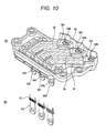
- FIGs. 10(A) and 10(B) are views describing an inverter terminal board according to the prior invention, and Fig. 10(A) is the whole perspective view, and Fig. 10(B) is a perspective view of motor side connecting terminals 50C.
- an inverter terminal board 40 is a container made by resin molding, and accommodates three bus bars 50 in the inside with the bus bars juxtaposed.
- Each of the bolt through holes 50B is bored in each of the inverter side connecting terminals 50T of the three bus bars 50, and each of the motor side connecting terminals 50C of the opposite side bends and extends vertically downward from a horizontally juxtaposed state inside the inverter terminal board 40, and the top of each of the motor side connecting terminals 50C is exposed from the inverter terminal board 40 and a bolt through hole 50S is bored.
- the output terminal 200T of the inverter 200 ( Fig. 9 ) is inserted into the bolt through hole 50B and is tightened with a nut.
- a bolt is inserted into the bolt through hole 50S and is tightened on the motor side terminal 100T ( Fig. 9 ) of the power receiving box 100C ( Fig. 9 ) of the side of the motor case 100 ( Fig. 9 ).
- Packing 30 for, for example, preventing an oil leak from a motor is attached to the motor side connecting terminal 50C.
- inverter side terminal 50T and the motor side connecting terminal 50C are formed in both ends of one bus bar 50, connection by a connector is eliminated and the vibration-resistant inverter terminal board is obtained. Also, since there is no connection by the connector, variations in a mechanical connection do not occur and the packing 30 sufficiently exerts a sealing effect on vibration and the inverter terminal board with good waterproof and oilproof properties is obtained.
- the motor side connecting terminal 50C may move and in that case, the bus bar 50 cannot absorb the variations since the bus bar 50 with high rigidity cannot follow its movement, so that there is a problem point in which a load is applied to other portions of the inverter terminal board.
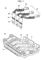
- Figs. 1(A) and 1(B) are exploded perspective views of an inverter terminal board according to the invention for further solving the problem described above while maintaining the merit of the inverter terminal board of Figs. 10(A) and 10(B) .
- Fig. 1(A) is a perspective view of three assemblies of connecting terminals and braided wires used as electric conductors of the inverter side
- Fig. 1(B) is a perspective view of the inverter terminal board for receiving the three braided wires of Fig. 1(A) in a juxtaposed state.
- Fig. 1(A) is a perspective view of three assemblies of connecting terminals and braided wires used as electric conductors of the inverter side
- Fig. 1(B) is a perspective view of the inverter terminal board for receiving the three braided wires of Fig. 1(A) in a juxtaposed state.
- Fig. 1(A) is a perspective view of three assemblies of connecting terminals
- electric conductors 20 are the electric conductors of three systems for supplying an AC three-phase current produced in the inverter side to the motor side, and each of the electric conductors includes an inverter side connecting terminal 20T, a braided wire 20H whose one end is connected to the inverter side connecting terminal 20T, and a motor side connecting terminal 20C having a caulked part 20S in which the other end of the braided wire 20H is caulked.
- an inverter terminal board 10 is a container in which the whole for respectively receiving the electric conductors 20 of three systems is molded of synthetic resin, and is provided with terminal receiving parts 10T for respectively receiving the inverter side connecting terminals 20T of the electric conductors 20 of three systems, braided wire receiving parts 10H for respectively receiving the braided wires 20H of three systems, and motor side connecting terminal insertion ports 10C (not seen in the drawing) into which the motor side connecting terminals 20C are inserted.
- Fig. 2 is a perspective view of a state of receiving the braided wires 20H of three systems in the inverter terminal board 10 of Fig. 1(B) .
- the inverter side connecting terminal 20T Fig. 2
- FIG. 1(A) ) of the electric conductor 20 is placed on the terminal receiving part 10T ( Fig. 1(B) ) and the braided wire 20H is placed on the braided wire receiving part 10H ( Fig. 1(B) ) and then, the motor side connecting terminal 20C inserted into the motor side connecting terminal insertion port 10C ( Fig. 1(B) ) protrudes from a lower portion of the inverter terminal board 10.
- This motor side connecting terminal 20C is attached to the motor side terminal 100T ( Fig. 9 ) of the power receiving box 100C of the other motor case 100 ( Fig. 9 ) with a bolt.
- Fig. 3 is a longitudinal sectional view showing the state of Fig.
- the braided wire 20H is attached to the inverter terminal board 10.
- the braided wire 20H attached to the inverter terminal board 10 is placed on the braided wire receiving part 10H and the end of the braided wire 20H is caulked in the caulked part 20S of the motor side connecting terminal 20C.
- the top of the other end of the motor side connecting terminal 20C downward protrudes from the inverter terminal board 10 (see Fig. 2 ).
- the packing 30 of Fig. 3 is the packing for preventing, for example, an oil leak from the motor, and the packing having two chevron parts (lip parts) over the entire periphery is used, and the packing capable of stably making contact with the other contact surface is formed.
- the packing 30 can obtain a long stroke of deformation.
- the two chevron parts are formed herein, but for a large installation area, three or more chevron parts can be formed.
- Fig. 4 is a conceptual diagram showing a state of placing the inverter terminal board 10 of the inverter 200 on the motor case 100, and a thin surface of the motor side connecting terminal 20C ( Fig. 1(A) ) with a thin rectangular flat plate shape is set at the front side.
- a thin surface of the motor side connecting terminal 20C Fig. 1(A)
- a thin rectangular flat plate shape is set at the front side.
- an amplitude of an X direction is large while amplitudes of Y and Z directions are small, so that by the two chevron parts present on the entire periphery of the packing 30, vibration of the X direction is applied to the inverter or the motor and the phase difference occurs between the inverter and the motor and even when relative movement occurs between the inverter and the motor, waterproof and oilproof functions can be performed sufficiently by providing the motor side connecting terminal 20C with the packing 30.
- Figs. 5(A) to 5(C) are sectional views describing the function of the packing 30, and Fig. 5(A) shows a state of the packing 30 at the time of no vibration, and Fig. 5(B) shows a state of the packing 30 at the time when the motor side connecting terminal 20C is displaced by vibration while maintaining a vertical state, and Fig. 5(C) represents a deformed state of each packing 30 at the time when the motor side connecting terminal 20C is inclined by vibration.
- Fig. 5(C) represents a deformed state of each packing 30 at the time when the motor side connecting terminal 20C is inclined by vibration.
- the packing 30 is in contact with a contact surface of the entire periphery, so that the packing function is fulfilled without any problem.
- the motor side connecting terminal 20C is displaced while maintaining the vertical state, so that the packing 30 is in contact with the contact surface of the entire periphery as can be seen from the drawing, with the result that the packing function is similarly fulfilled without any problem.
- the motor side connecting terminal 20C is inclined at the time of vibration as shown Fig. 5(C) , a portion of the chevron part is separated from the contact surface in the packing 30, so that it was revealed that the packing function cannot be effectively fulfilled even for the packing 30 of the first embodiment.
- a second embodiment has been implemented in order to solve such a problem of the first embodiment, and is constructed so as to provide both upper and lower ends of packing with spacers by noticing that the motor side connecting terminal 20C could be prevented from being inclined as shown Fig. 5(C) even for vibration.
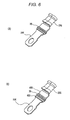
- Fig. 6(A) is a perspective view seen from the back side of the motor side connecting terminal 20C representing the packing 30 of the first embodiment
- Fig. 6(B) is a perspective view seen from the back side of the motor side connecting terminal 20C representing the packing 30 of the first embodiment and an upper spacer 40U and a lower spacer 40S with which both ends of the packing 30 are provided.
- Both of the upper spacer 40U and the lower spacer 40S have the same shape made of the same material, and have an oval shape in plan view and have the shape in which a hole through which the motor side connecting terminal 20C extends is bored in the center.
- Fig. 7 is a perspective view of an electric conductor of the inverter side in which the upper spacer 40U and the lower spacer 40S are attached to both upper and lower ends of each packing 30 ( Fig. 1 (A) ) of the first embodiment.
- electric conductors 20 are the electric conductors of three systems for supplying an AC three-phase current produced in the inverter side to the motor side, and each of the electric conductors includes an inverter side connecting terminal 20T, a braided wire 20H whose one end is connected to the inverter side connecting terminal 20T, and a motor side connecting terminal 20C having a caulked part 20S in which the other end of the braided wire 20H is caulked.
- Figs. 8(A) and 8(B) are sectional views describing a function of such upper and lower spacers 40U, 40S, and Fig. 8(A) shows a state of the packing 30 at the time of no vibration, and Fig. 8(B) represents a deformed state of each packing 30 at the time of vibration.
- the packing 30 is in contact with a contact surface of the entire periphery, so that the packing function is fulfilled without any problem.
- the motor side connecting terminal 20C is displaced while maintaining the vertical state by the upper and lower spacers 40U, 40S even when large relative movement occurs between the inverter and the motor and the motor side connecting terminal 20C attempts to be inclined, so that the second embodiment can obtain an effect in which the packing 30 of the first embodiment can continue to fulfill the packing function without any problem.
Landscapes
- Engineering & Computer Science (AREA)
- Power Engineering (AREA)
- Microelectronics & Electronic Packaging (AREA)
- Motor Or Generator Frames (AREA)
Abstract
Description
- The present invention relates to a suitable inverter terminal board unaffected by vibration under an environment of occurrence of the vibration in the case of installing an inverter used for a vehicle etc. in a motor case.
- An electric vehicle or a hybrid electric vehicle generally includes a motor and an inverter between a battery and wheels in order to drive the wheels by electric power accumulated in the battery.
The electric power accumulated in the battery is converted by the inverter of an inverter device etc. and is supplied to the motor and rotates the motor, and rotation of the motor is transmitted to the wheels and drives the wheels.
Conventionally, the inverter and the motor were mounted in separate places of the vehicle and a terminal of the inverter was connected to a terminal of the motor using a wire harness.
On the other hand, a structure of integrating an inverter with a motor for the purpose of cost reduction and miniaturization of an electric driving system from a battery to wheels has been proposed recently (Patent Reference 1 or 2). -
Fig. 9 is a conceptual diagram of an invention of integrating an inverter with a motor described in Patent Reference 1 or 2, and a power receiving box 100C is placed on amotor case 100 for accommodating a three-phase AC motor (an induction motor or a synchronous machine) and threemotor side terminals 100T for receiving three-phase AC electric power are attached to the power receiving box 100C and on the other hand,output terminals 200T of aninverter 200 for receiving a DC from a DC power source placed on the other part of a vehicle and converting the DC into an three-phase AC are attached. Then, a vibration-resistant terminal board targeted for the invention is used for supplying the three-phase AC electric power of theinverter 200 from theoutput terminals 200T to themotor side terminals 100T of the power receiving box 100C of the side of themotor case 100. - After the
motor case 100 and theinverter 200 are assembled separately, theinverter 200 is installed in the vicinity of themotor case 100 and also theoutput terminals 200T of theinverter 200 are connected to themotor side terminals 100T of themotor case 100 by the terminal board and thereby, theinverter 200 and themotor case 100 can be assembled and manufactured as separate modules and are only connected by the terminal board at the time of integration, so that manufacture is easy and cost can be reduced. - However, in such a configuration, a vibration phase difference between the inverter and the motor by vibration of the motor itself or vibration of a vehicle body at the time of driving is applied to a connector and the connector may be damaged. Therefore, it is necessary to develop a connector capable of withstanding such vibration.
Then, a connector described in Patent Reference 3 is disclosed as the connector capable of withstanding such vibration. -
- Patent Reference 1:
JP-A-5-219607 - Patent Reference 2:
JP-A-2004-312853 - Patent Reference 3:
JP-A-2007-280913 - The connector described in Patent Reference 3 is characterized in that in the connector for connecting an inverter terminal to a motor terminal, an inverter cabinet and the inverter terminal and a motor cabinet and the motor terminal are included and while the motor terminal is fixed and attached to the motor cabinet, the inverter terminal is attached to the inverter cabinet through a vibration absorber.
- Since the terminal of one device is attached to the cabinet of its device through the vibration absorber thus, even when vibration by a phase difference is applied to one device and the other device, its vibration is absorbed by the vibration absorber, so that an extra load is not applied to a connector connection and adverse influences of damage etc. can be prevented.
- However, the connector described in Patent Reference 3 has a problem that a mechanical connection of the connector is susceptible to vibration since a motor side connecting terminal is connected to an inverter side terminal by the connector.
Also, waterproof properties at the time of absorption in the case of variations due to assembly tolerances of a motor and an inverter are insufficient and there is no structure of preventing an oil leak from the motor.
Therefore, even when the vibration absorber is included, vibration of the connection cannot be eliminated completely and the mechanical connection of the connector may cause bad connection due to the long-term vibration.
Also, when vibration varies greatly in the case of great variations due to the assembly tolerances of the motor and the inverter, the mechanical connection of the connector cannot prevent the vibration sufficiently and even when packing is received in the inside, its packing does not function effectively and there is fear that water immersion or an oil leak cannot be prevented. - The invention has been implemented in order to solve the problem described above, and an object of the invention is to provide an inverter terminal board capable of being made resistant to vibration by stopping connection between a motor side connecting terminal and an inverter side terminal by a connector and sufficiently performing waterproof and oilproof functions and sufficiently exerting a sealing effect on vibration even in the case of great variations due to assembly tolerances of a motor and an inverter.
- In order to solve the problem described above, a first invention of the present application is an inverter terminal board including an electric conductor which has an inverter side connecting terminal connected to an output terminal of an inverter attached to a motor case and a motor side connecting terminal connected to a power receiving terminal of the motor and is made by connecting the inverter side connecting terminal to the motor side connecting terminal by a braided wire, wherein a flat plate-shaped long terminal is used as the motor side connecting terminal and the middle of the flat plate-shaped long terminal is covered with packing.
- Also, in the first invention, a second invention is wherein in the packing, two or more chevron parts are formed in longitudinal sectional view.
Also, in the first invention, a third invention is wherein in that both ends of the packing attached to the motor side connecting terminal are provided with spacers. - According to the first invention as described above, a connector connection is eliminated, and connection between the motor side connecting terminal of the inverter terminal board and the power receiving terminal of the motor and connection between the inverter side connecting terminal and the output terminal of the inverter are coupled by bolts and the motor side connecting terminal is connected to the inverter side connecting terminal by the braided wire, so that the vibration-resistant inverter terminal board can be obtained and even in the case of great variations due to assembly tolerances of the motor and the inverter, the packing with which the entire periphery of the flat plate-shaped long terminal is covered can sufficiently exert a sealing effect on vibration and the braided wire can conform with a weakness (susceptibility to displacement) by using the packing, so that the inverter terminal board in which a load is not applied to the terminal can be obtained.
- According to the second invention, the packing has elasticity by the two chevron parts and can obtain a long stroke of deformation and can also fit stably. The packing capable of sufficiently exerting the sealing effect on vibration can be obtained.
According to the third invention, even at the time of large vibration, the motor side connecting terminal can maintain a vertical state, so that the sealing effect on the vibration can be exerted sufficiently. -
- Both
Figs. 1(A) and 1(B) construct an exploded perspective view of an inverter terminal board to which the invention is applied, andFig. 1(A) shows an assembly of a braided wire and connecting terminals in the case of using the braided wire in an electric conductor of the inverter side andFig. 1(B) shows the inverter terminal board for receiving the assembly ofFig. 1 (A) . -
Fig. 2 is a perspective view showing a state of receiving the assembly ofFig. 1(A) in the inverter terminal board ofFig. 1 (B) . -
Fig. 3 is a longitudinal sectional view showing the state ofFig. 2 . -
Fig. 4 is a conceptual diagram describing vibration in a state of placing an inverter having the inverter terminal board on a motor case. -
Figs. 5(A) to 5(C) are sectional views describing a function of packing, andFig. 5(A) shows a state of the packing at the time of no vibration, andFig. 5(B) shows a state of the packing at the time when a motor side connecting terminal is displaced by vibration while maintaining a vertical state, andFig. 5(C) represents a deformed state of the packing at the time when the motor side connecting terminal is inclined by vibration. In addition,Fig. 5(A) shows the original shape of the normal packing by representing lip parts of the packing in a state in which an external force is not applied to an inner peripheral surface of the inverter terminal board intentionally by dotted lines. That is, note that use of the dotted lines in the lip parts of the packing does not indicate that the packing bites into the inverter terminal board. -
Fig. 6(A) is a perspective view seen from the back side of the motor side connecting terminal representing the packing of a first embodiment, andFig. 6(B) is a perspective view seen from the back side of the motor side connecting terminal representing the packing of the first embodiment and an upper spacer and a lower spacer with which both ends of the packing are provided. -
Fig. 7 is a perspective view of an assembly in which the upper spacer and the lower spacer are attached to both upper and lower ends of each packing of the assembly ofFig. 1(A) . -
Figs. 8(A) and 8(B) are sectional views describing a function of the upper and lower spacers ofFig. 7 , andFig. 8(A) shows a state of the packing at the time of no vibration, andFig. 8(B) represents a deformed state of the packing at the time of vibration. In addition,Fig. 8(A) shows the original shape of the normal packing by representing lip parts of the packing in a state in which an external force is not applied to an inner peripheral surface of the inverter terminal board intentionally by dotted lines. That is, note that use of the dotted lines in the lip parts of the packing does not indicate that the packing bites into the inverter terminal board. -
Fig. 9 is a conceptual diagram of an invention of integrating an inverter with a motor described in Patent Reference 1 or 2. -
Fig. 10(A) is a perspective view of an inverter terminal board according to a prior invention serving as a basis for the invention andFig. 10(B) is a perspective view of each of the motor side connecting terminals. - First and second embodiments of vibration-resistant packing of the invention capable of sufficiently exerting a sealing effect on vibration even in the case of great variations due to assembly tolerances of a motor and an inverter will hereinafter be described based on the drawings.
- A prior invention serving as a basis for producing the invention will be described before describing the invention.
Figs. 10(A) and 10(B) are views describing an inverter terminal board according to the prior invention, andFig. 10(A) is the whole perspective view, andFig. 10(B) is a perspective view of motorside connecting terminals 50C. InFig. 10(A) , aninverter terminal board 40 is a container made by resin molding, and accommodates threebus bars 50 in the inside with the bus bars juxtaposed.
Each of the bolt throughholes 50B is bored in each of the inverterside connecting terminals 50T of the threebus bars 50, and each of the motorside connecting terminals 50C of the opposite side bends and extends vertically downward from a horizontally juxtaposed state inside theinverter terminal board 40, and the top of each of the motorside connecting terminals 50C is exposed from theinverter terminal board 40 and a bolt throughhole 50S is bored. Theoutput terminal 200T of the inverter 200 (Fig. 9 ) is inserted into the bolt throughhole 50B and is tightened with a nut. A bolt is inserted into the bolt throughhole 50S and is tightened on themotor side terminal 100T (Fig. 9 ) of the power receiving box 100C (Fig. 9 ) of the side of the motor case 100 (Fig. 9 ). Packing 30 for, for example, preventing an oil leak from a motor is attached to the motorside connecting terminal 50C. - Since the
inverter side terminal 50T and the motor side connecting terminal 50C are formed in both ends of onebus bar 50, connection by a connector is eliminated and the vibration-resistant inverter terminal board is obtained.
Also, since there is no connection by the connector, variations in a mechanical connection do not occur and the packing 30 sufficiently exerts a sealing effect on vibration and the inverter terminal board with good waterproof and oilproof properties is obtained. - Since the packing 30 is made of rubber, the motor side connecting terminal 50C may move and in that case, the
bus bar 50 cannot absorb the variations since thebus bar 50 with high rigidity cannot follow its movement, so that there is a problem point in which a load is applied to other portions of the inverter terminal board. -
Figs. 1(A) and 1(B) are exploded perspective views of an inverter terminal board according to the invention for further solving the problem described above while maintaining the merit of the inverter terminal board ofFigs. 10(A) and 10(B) .Fig. 1(A) is a perspective view of three assemblies of connecting terminals and braided wires used as electric conductors of the inverter side, andFig. 1(B) is a perspective view of the inverter terminal board for receiving the three braided wires ofFig. 1(A) in a juxtaposed state.
InFig. 1(A) ,electric conductors 20 are the electric conductors of three systems for supplying an AC three-phase current produced in the inverter side to the motor side, and each of the electric conductors includes an inverter side connecting terminal 20T, abraided wire 20H whose one end is connected to the inverter side connecting terminal 20T, and a motor side connecting terminal 20C having a caulkedpart 20S in which the other end of thebraided wire 20H is caulked.
Since theflexible braided wire 20H is interposed between the inverter side connecting terminal 20T and the motor side connecting terminal 20C by the first embodiment of the invention, unlike intervention of the bus bar with high rigidity, vibration applied to the inverter side connecting terminal 20T is absorbed by thebraided wire 20H and is not transmitted to the motor side connecting terminal 20C.
Also, packing 30 is attached to the motor side connecting terminal 20C so as to surround the motor side connecting terminal 20C.
InFig. 1(B) , aninverter terminal board 10 is a container in which the whole for respectively receiving theelectric conductors 20 of three systems is molded of synthetic resin, and is provided withterminal receiving parts 10T for respectively receiving the inverterside connecting terminals 20T of theelectric conductors 20 of three systems, braidedwire receiving parts 10H for respectively receiving thebraided wires 20H of three systems, and motor side connectingterminal insertion ports 10C (not seen in the drawing) into which the motorside connecting terminals 20C are inserted.
Fig. 2 is a perspective view of a state of receiving thebraided wires 20H of three systems in theinverter terminal board 10 ofFig. 1(B) . InFig. 2 , the inverter side connecting terminal 20T (Fig. 1(A) ) of theelectric conductor 20 is placed on theterminal receiving part 10T (Fig. 1(B) ) and thebraided wire 20H is placed on the braidedwire receiving part 10H (Fig. 1(B) ) and then, the motor side connecting terminal 20C inserted into the motor side connectingterminal insertion port 10C (Fig. 1(B) ) protrudes from a lower portion of theinverter terminal board 10. This motor side connecting terminal 20C is attached to themotor side terminal 100T (Fig. 9 ) of the power receiving box 100C of the other motor case 100 (Fig. 9 ) with a bolt.
Fig. 3 is a longitudinal sectional view showing the state ofFig. 2 in which thebraided wire 20H is attached to theinverter terminal board 10. InFig. 3 , thebraided wire 20H attached to theinverter terminal board 10 is placed on the braidedwire receiving part 10H and the end of thebraided wire 20H is caulked in the caulkedpart 20S of the motor side connecting terminal 20C. The top of the other end of the motor side connecting terminal 20C downward protrudes from the inverter terminal board 10 (seeFig. 2 ). - The packing 30 of
Fig. 3 is the packing for preventing, for example, an oil leak from the motor, and the packing having two chevron parts (lip parts) over the entire periphery is used, and the packing capable of stably making contact with the other contact surface is formed. By contraction and expansion of the two chevron parts, the packing 30 can obtain a long stroke of deformation. In addition, the two chevron parts are formed herein, but for a large installation area, three or more chevron parts can be formed. -
Fig. 4 is a conceptual diagram showing a state of placing theinverter terminal board 10 of theinverter 200 on themotor case 100, and a thin surface of the motor side connecting terminal 20C (Fig. 1(A) ) with a thin rectangular flat plate shape is set at the front side. When magnitude of vibration applied to the inverter or the motor is shown by the X, Y and Z axes (seeFig. 2 ) of three dimensions, an amplitude of an X direction is large while amplitudes of Y and Z directions are small, so that by the two chevron parts present on the entire periphery of the packing 30, vibration of the X direction is applied to the inverter or the motor and the phase difference occurs between the inverter and the motor and even when relative movement occurs between the inverter and the motor, waterproof and oilproof functions can be performed sufficiently by providing the motor side connecting terminal 20C with the packing 30. - As described above, a packing function is effectively fulfilled with respect to vibration by using the packing 30, but the subsequent experiment revealed that a packing leak occurs under specific conditions. The cause will be described using
Figs. 5(A) to 5(C) .
Figs. 5(A) to 5(C) are sectional views describing the function of the packing 30, andFig. 5(A) shows a state of the packing 30 at the time of no vibration, andFig. 5(B) shows a state of the packing 30 at the time when the motor side connecting terminal 20C is displaced by vibration while maintaining a vertical state, andFig. 5(C) represents a deformed state of each packing 30 at the time when the motor side connecting terminal 20C is inclined by vibration.
At the time of no vibration ofFig. 5(A) , the packing 30 is in contact with a contact surface of the entire periphery, so that the packing function is fulfilled without any problem.
At the time of vibration ofFig. 5(B) , the motor side connecting terminal 20C is displaced while maintaining the vertical state, so that the packing 30 is in contact with the contact surface of the entire periphery as can be seen from the drawing, with the result that the packing function is similarly fulfilled without any problem.
However, when the motor side connecting terminal 20C is inclined at the time of vibration as shownFig. 5(C) , a portion of the chevron part is separated from the contact surface in the packing 30, so that it was revealed that the packing function cannot be effectively fulfilled even for the packing 30 of the first embodiment. - A second embodiment has been implemented in order to solve such a problem of the first embodiment, and is constructed so as to provide both upper and lower ends of packing with spacers by noticing that the motor side connecting terminal 20C could be prevented from being inclined as shown
Fig. 5(C) even for vibration. -
Fig. 6(A) is a perspective view seen from the back side of the motor side connecting terminal 20C representing the packing 30 of the first embodiment, andFig. 6(B) is a perspective view seen from the back side of the motor side connecting terminal 20C representing the packing 30 of the first embodiment and anupper spacer 40U and alower spacer 40S with which both ends of the packing 30 are provided. Both of theupper spacer 40U and thelower spacer 40S have the same shape made of the same material, and have an oval shape in plan view and have the shape in which a hole through which the motor side connecting terminal 20C extends is bored in the center. -
Fig. 7 is a perspective view of an electric conductor of the inverter side in which theupper spacer 40U and thelower spacer 40S are attached to both upper and lower ends of each packing 30 (Fig. 1 (A) ) of the first embodiment.
InFig. 7 ,electric conductors 20 are the electric conductors of three systems for supplying an AC three-phase current produced in the inverter side to the motor side, and each of the electric conductors includes an inverter side connecting terminal 20T, abraided wire 20H whose one end is connected to the inverter side connecting terminal 20T, and a motor side connecting terminal 20C having a caulkedpart 20S in which the other end of thebraided wire 20H is caulked. Then, the packing 30 according to the first embodiment of the invention for surrounding the motor side connecting terminal 20C and theupper spacer 40U and thelower spacer 40S according to the second embodiment are attached to the motor side connecting terminal 20C.
Figs. 8(A) and 8(B) are sectional views describing a function of such upper andlower spacers Fig. 8(A) shows a state of the packing 30 at the time of no vibration, andFig. 8(B) represents a deformed state of each packing 30 at the time of vibration.
At the time of no vibration ofFig. 8(A) , the packing 30 is in contact with a contact surface of the entire periphery, so that the packing function is fulfilled without any problem. At the time of vibration ofFig. 8(B) , even when the motor side connecting terminal 20C attempts to be displaced and inclined in the hole, upper and lower portions of the motor side connecting terminal 20C are regulated by the upper andlower spacers Fig. 5(C) , so that the packing function can be fulfilled without any problem. - When only the packing 30 is attached to the motor side connecting terminal 20C without the upper and
lower spacers lower spacers lower spacers - By providing both ends of the packing 30 with the upper and
lower spacers lower spacers - The present application is based on Japanese patent application (patent application No.
2009-255278) filed on November 6, 2009 -
- 10
- INVERTER TERMINAL BOARD
- 10C
- MOTOR SIDE CONNECTING TERMINAL INSERTION PORT
- 10H
- BRAIDED WIRE RECEIVING PART
- 10T
- TERMINAL RECEIVING PART
- 20
- ELECTRIC CONDUCTOR
- 20C
- MOTOR SIDE CONNECTING TERMINAL
- 20H
- BRAIDED WIRE
- 20S
- CAULKED PART
- 20T
- INVERTER SIDE CONNECTING TERMINAL
- 30
- PACKING
- 40S
- LOWER SPACER
- 40U
- UPPER SPACER
- 100
- MOTOR CASE
- 100C
- POWER RECEIVING BOX
- 100T
- MOTOR SIDE TERMINAL
- 200
- INVERTER
- 200T
- OUTPUT TERMINAL
Claims (3)
- An inverter terminal board, comprising:an electric conductor which has an inverter side connecting terminal connected to an output terminal of an inverter attached to a motor case, and a motor side connecting terminal connected to a power receiving terminal of the motor, the electric conductor board being made by connecting the inverter side connecting terminal to the motor side connecting terminal by a braided wire,wherein a flat plate-shaped long terminal is used as the motor side connecting terminal and the middle of the flat plate-shaped long terminal is covered with packing.
- The inverter terminal board as claimed in claim 1, wherein in the packing, two or more chevron parts are formed in longitudinal sectional view.
- The inverter terminal board as claimed in claim 1, wherein both ends of the packing attached to the motor side connecting terminal are provided with spacers.
Applications Claiming Priority (2)
| Application Number | Priority Date | Filing Date | Title |
|---|---|---|---|
| JP2009255278 | 2009-11-06 | ||
| PCT/JP2010/069757 WO2011055806A1 (en) | 2009-11-06 | 2010-11-05 | Inverter terminal block provided to motor case |
Publications (3)
| Publication Number | Publication Date |
|---|---|
| EP2498383A1 true EP2498383A1 (en) | 2012-09-12 |
| EP2498383A4 EP2498383A4 (en) | 2017-11-15 |
| EP2498383B1 EP2498383B1 (en) | 2020-02-12 |
Family
ID=43970042
Family Applications (1)
| Application Number | Title | Priority Date | Filing Date |
|---|---|---|---|
| EP10828365.6A Active EP2498383B1 (en) | 2009-11-06 | 2010-11-05 | Inverter terminal block provided to motor case |
Country Status (5)
| Country | Link |
|---|---|
| US (1) | US9112397B2 (en) |
| EP (1) | EP2498383B1 (en) |
| JP (1) | JP5410542B2 (en) |
| CN (1) | CN102362412A (en) |
| WO (1) | WO2011055806A1 (en) |
Cited By (4)
| Publication number | Priority date | Publication date | Assignee | Title |
|---|---|---|---|---|
| ITBO20120682A1 (en) * | 2012-12-18 | 2014-06-19 | Spal Automotive Srl | ELECTRIC MACHINE |
| WO2015078459A3 (en) * | 2013-11-26 | 2015-12-30 | Schaeffler Technologies AG & Co. KG | Power electronics module and hybrid module with an e-motor power connection |
| US9882315B2 (en) | 2012-12-10 | 2018-01-30 | Rosenberger Hochfrequenztechnik Gmbh & Co. Kg | Connection device |
| DE102018112900A1 (en) * | 2018-05-30 | 2019-12-05 | Kiekert Aktiengesellschaft | Electric drive unit for automotive applications |
Families Citing this family (51)
| Publication number | Priority date | Publication date | Assignee | Title |
|---|---|---|---|---|
| JP5751875B2 (en) * | 2011-03-22 | 2015-07-22 | 矢崎総業株式会社 | Shield connector |
| US9318849B2 (en) * | 2011-04-14 | 2016-04-19 | Yazaki Corporation | Shielded connector |
| JP5720593B2 (en) * | 2012-02-02 | 2015-05-20 | 株式会社豊田自動織機 | Electric compressor |
| DE102012209919A1 (en) | 2012-06-13 | 2013-12-19 | Hilti Aktiengesellschaft | Hand tool |
| JP2014011134A (en) * | 2012-07-03 | 2014-01-20 | Auto Network Gijutsu Kenkyusho:Kk | connector |
| JP6071448B2 (en) * | 2012-11-13 | 2017-02-01 | 矢崎総業株式会社 | connector |
| ES2699987T3 (en) * | 2013-03-22 | 2019-02-13 | Mitsuba Corp | Motor device |
| EP2796723A1 (en) * | 2013-04-26 | 2014-10-29 | Pierburg Pump Technology GmbH | Electric motor with flexible wire between stator coils and PCB |
| JP6024986B2 (en) * | 2013-05-30 | 2016-11-16 | 株式会社オートネットワーク技術研究所 | Terminal block |
| JP6268915B2 (en) * | 2013-10-24 | 2018-01-31 | 住友電装株式会社 | connector |
| JP5967063B2 (en) | 2013-12-13 | 2016-08-10 | 株式会社オートネットワーク技術研究所 | connector |
| US20150171578A1 (en) * | 2013-12-13 | 2015-06-18 | Delphi Technologies, Inc. | Braided wire connection for an electronics assembly |
| US10003235B2 (en) * | 2014-01-08 | 2018-06-19 | Continental Automotive Systems, Inc. | Flexible connector system for connecting a high current motor to a PCB of an integrated electronics system of a vehicle |
| JP6501360B2 (en) * | 2014-08-22 | 2019-04-17 | 日本電産株式会社 | Module, power converter and motor using the module |
| WO2016035476A1 (en) * | 2014-09-02 | 2016-03-10 | アイシン・エィ・ダブリュ株式会社 | Terminal base |
| KR102311636B1 (en) * | 2014-11-10 | 2021-10-12 | 현대모비스 주식회사 | Direct-connect connector and connecting structure thereof |
| JP6140129B2 (en) | 2014-11-14 | 2017-05-31 | 古河電気工業株式会社 | Terminal block and terminal block unit |
| JP2016119188A (en) * | 2014-12-19 | 2016-06-30 | 株式会社オートネットワーク技術研究所 | Flexible connection terminal and power storage module |
| JP6319633B2 (en) * | 2015-01-28 | 2018-05-09 | 住友電装株式会社 | Connector for equipment |
| JP6413799B2 (en) * | 2015-01-28 | 2018-10-31 | 住友電装株式会社 | Connector for equipment |
| JP6492929B2 (en) * | 2015-04-23 | 2019-04-03 | 住友電装株式会社 | connector |
| JP6520425B2 (en) * | 2015-06-08 | 2019-05-29 | 株式会社オートネットワーク技術研究所 | Elastic shield member for equipment |
| DE102015213439A1 (en) * | 2015-07-17 | 2017-01-19 | Zf Friedrichshafen Ag | Power connection for an electrical device, in particular for an electrical machine for driving a motor vehicle |
| JP6654851B2 (en) * | 2015-10-20 | 2020-02-26 | 日立金属株式会社 | Connecting component for rotating electric machine and method of manufacturing the same |
| JP6072887B1 (en) * | 2015-12-07 | 2017-02-01 | 三菱電機株式会社 | Rotating electric machine |
| KR102579445B1 (en) * | 2015-12-07 | 2023-09-15 | 현대모비스 주식회사 | Starter generator |
| DE102015122250A1 (en) * | 2015-12-18 | 2017-06-22 | Karlsruher Institut für Technologie | Multifunctional module connection structure |
| FR3047126B1 (en) * | 2016-01-26 | 2019-08-02 | Valeo Systemes Thermiques | ELECTRIC MOTOR AIR PULSING DEVICE AND METHOD FOR GUIDING THE CONNECTORS THEREOF |
| IT201600095895A1 (en) * | 2016-09-23 | 2018-03-23 | Magneti Marelli Spa | ELECTRIC DRIVE SYSTEM FOR AUTOMOTIVE |
| KR102625858B1 (en) * | 2016-10-12 | 2024-01-16 | 현대모비스 주식회사 | Connector installation structure for starter generator |
| JP6723141B2 (en) * | 2016-11-11 | 2020-07-15 | 三菱重工サーマルシステムズ株式会社 | Capacitor unit, electric compressor |
| US10717401B2 (en) * | 2017-04-21 | 2020-07-21 | Ford Global Technologies, Llc | Terminal block assembly for electrified vehicles |
| DE102017213150A1 (en) * | 2017-07-31 | 2019-01-31 | Robert Bosch Gmbh | Electrical plug contact for high current applications and connector system for high current applications |
| JP6946967B2 (en) * | 2017-11-22 | 2021-10-13 | 住友電装株式会社 | Terminal holder, wire harness, fixed structure |
| DE102018206293A1 (en) * | 2018-04-24 | 2019-10-24 | Zf Friedrichshafen Ag | An interface device for a vehicle, a drive system for a vehicle, and a method for mounting a drive system for a vehicle |
| DE102018109863B4 (en) * | 2018-04-24 | 2020-01-16 | Lisa Dräxlmaier GmbH | Multi-component seal for sealing a rail, in particular a busbar for an electrical system of a motor vehicle, against a housing |
| EP3921926B1 (en) * | 2019-02-08 | 2025-01-15 | GKN Automotive Limited | Connector assembly and a method for electrically connecting an inverter busbar to an electrical connector of a drive unit and such a drive unit |
| JP6957541B2 (en) * | 2019-02-25 | 2021-11-02 | 本田技研工業株式会社 | Busbar unit |
| FR3097715B1 (en) * | 2019-06-21 | 2021-07-16 | Valeo Equip Electr Moteur | Electronic system with electronic measuring device and comprising a seal and electrical assembly comprising such an electronic system |
| DE102019124229A1 (en) * | 2019-09-10 | 2021-03-11 | Schaeffler Technologies AG & Co. KG | Power electronics module with sealing jacket attached via an adhesion promoter; electric prime mover; as well as manufacturing processes |
| CN110571751B (en) * | 2019-09-30 | 2024-09-20 | 江苏华侃核电器材科技有限公司 | Special-shaped cable intermediate joint for nuclear power station |
| CN110797814A (en) * | 2019-10-25 | 2020-02-14 | 天津航空机电有限公司 | A sealed insulated junction box with error compensation |
| CN114830459B (en) * | 2019-12-18 | 2023-12-22 | 丰田自动车株式会社 | Wire side connector |
| JP7328624B2 (en) | 2020-02-04 | 2023-08-17 | 株式会社オートネットワーク技術研究所 | Terminal connection unit |
| JP7342766B2 (en) * | 2020-03-31 | 2023-09-12 | 株式会社豊田自動織機 | electric compressor |
| GB2594451B (en) * | 2020-04-22 | 2022-09-14 | Delphi Automotive Systems Lux | Vehicle inverter sealing arrangement |
| US11888257B2 (en) * | 2021-05-13 | 2024-01-30 | Schaeffler Technologies AG & Co. KG | High voltage connection for busbar assembly |
| JP7518106B2 (en) * | 2022-01-17 | 2024-07-17 | 矢崎総業株式会社 | Terminal connection structure and connector |
| JP7795398B2 (en) | 2022-03-30 | 2026-01-07 | 本田技研工業株式会社 | Conductive Unit |
| DE102022209751A1 (en) * | 2022-09-16 | 2024-03-21 | Zf Friedrichshafen Ag | Connection device for electrically connecting a power converter to an electric machine for an electric axle drive of a motor vehicle, electric axle drive for a motor vehicle, motor vehicle, method for producing a connection device and method for assembling an electric axle drive |
| JP7618719B2 (en) * | 2023-03-27 | 2025-01-21 | 本田技研工業株式会社 | Terminal Blocks |
Family Cites Families (23)
| Publication number | Priority date | Publication date | Assignee | Title |
|---|---|---|---|---|
| FR1589128A (en) * | 1968-09-06 | 1970-03-23 | ||
| JP3253342B2 (en) | 1992-02-07 | 2002-02-04 | 富士電機株式会社 | Electric vehicle drive system |
| US5517401A (en) | 1992-02-07 | 1996-05-14 | Fuji Electric Co., Ltd. | Three level pulse width modulated inverter for an electric vehicle |
| JPH10201202A (en) * | 1996-12-27 | 1998-07-31 | Mitsuba Corp | Electric motor structure |
| JP4020358B2 (en) * | 2001-10-01 | 2007-12-12 | 矢崎総業株式会社 | Terminal oil-proof water structure |
| AU2003225205A1 (en) * | 2002-04-30 | 2003-11-17 | Corning Gilbert Inc. | Apparatus for electrically coupling a linear conductor to a surface conductor and related method |
| JP3816888B2 (en) | 2003-04-04 | 2006-08-30 | 株式会社日立製作所 | Vehicle drive unit and vehicle drive device |
| JP2004349026A (en) * | 2003-05-20 | 2004-12-09 | Yazaki Corp | Holder and connector |
| US7186138B2 (en) * | 2004-12-22 | 2007-03-06 | Insert Enterprise Co., Ltd. | Multiple pieces dual type BNC connector with all metal shell |
| WO2007026894A1 (en) * | 2005-09-01 | 2007-03-08 | Nsk Ltd. | Electric power steering device |
| JP2007080692A (en) | 2005-09-14 | 2007-03-29 | Auto Network Gijutsu Kenkyusho:Kk | Shield conductor |
| JP4290153B2 (en) * | 2005-11-01 | 2009-07-01 | 東邦瓦斯株式会社 | Leakage prevention device for cryogenic flange joints |
| JP4550791B2 (en) * | 2005-11-24 | 2010-09-22 | 古河電気工業株式会社 | Aluminum stranded wire crimp terminal and aluminum stranded wire terminal structure to which the crimp terminal is connected |
| US7462031B2 (en) * | 2005-11-25 | 2008-12-09 | Mold-Masters (2007) Limited | Injection molding nozzle with recessed terminal |
| JP4816149B2 (en) * | 2006-03-06 | 2011-11-16 | トヨタ自動車株式会社 | Connection wire presser structure |
| JP4665848B2 (en) * | 2006-03-15 | 2011-04-06 | 日立電線株式会社 | Connector structure |
| US7503799B2 (en) * | 2006-08-28 | 2009-03-17 | Commscope Inc. | Communications plug with reverse cordage and anti-snag configuration |
| JP4556935B2 (en) * | 2006-10-05 | 2010-10-06 | 株式会社デンソー | Starter |
| JP2008130388A (en) * | 2006-11-21 | 2008-06-05 | Yazaki Corp | Seal structure of terminal insertion part |
| JP2009255278A (en) | 2008-03-28 | 2009-11-05 | Hitachi Metals Ltd | Sheet puncher |
| JP5721332B2 (en) * | 2010-03-05 | 2015-05-20 | 矢崎総業株式会社 | Inverter terminal block installed in the motor case |
| JP5654306B2 (en) * | 2010-09-30 | 2015-01-14 | 矢崎総業株式会社 | Conductive path connection structure |
| JP5831061B2 (en) * | 2011-01-19 | 2015-12-09 | 日立金属株式会社 | connector |
-
2010
- 2010-11-05 EP EP10828365.6A patent/EP2498383B1/en active Active
- 2010-11-05 US US13/254,877 patent/US9112397B2/en active Active
- 2010-11-05 CN CN2010800128768A patent/CN102362412A/en active Pending
- 2010-11-05 JP JP2011539409A patent/JP5410542B2/en active Active
- 2010-11-05 WO PCT/JP2010/069757 patent/WO2011055806A1/en not_active Ceased
Non-Patent Citations (1)
| Title |
|---|
| See references of WO2011055806A1 * |
Cited By (7)
| Publication number | Priority date | Publication date | Assignee | Title |
|---|---|---|---|---|
| US9882315B2 (en) | 2012-12-10 | 2018-01-30 | Rosenberger Hochfrequenztechnik Gmbh & Co. Kg | Connection device |
| ITBO20120682A1 (en) * | 2012-12-18 | 2014-06-19 | Spal Automotive Srl | ELECTRIC MACHINE |
| WO2014097109A1 (en) * | 2012-12-18 | 2014-06-26 | Spal Automotive S.R.L. | Electrical machine. |
| US9997971B2 (en) | 2012-12-18 | 2018-06-12 | Spal Automotive S.R.L. | Electrical machine |
| WO2015078459A3 (en) * | 2013-11-26 | 2015-12-30 | Schaeffler Technologies AG & Co. KG | Power electronics module and hybrid module with an e-motor power connection |
| US10658900B2 (en) | 2013-11-26 | 2020-05-19 | Schaeffler Technologies AG & Co. KG | Power electronics module and hybrid module with an E-motor power connection |
| DE102018112900A1 (en) * | 2018-05-30 | 2019-12-05 | Kiekert Aktiengesellschaft | Electric drive unit for automotive applications |
Also Published As
| Publication number | Publication date |
|---|---|
| EP2498383B1 (en) | 2020-02-12 |
| JPWO2011055806A1 (en) | 2013-03-28 |
| US20110316373A1 (en) | 2011-12-29 |
| WO2011055806A1 (en) | 2011-05-12 |
| JP5410542B2 (en) | 2014-02-05 |
| EP2498383A4 (en) | 2017-11-15 |
| CN102362412A (en) | 2012-02-22 |
| US9112397B2 (en) | 2015-08-18 |
Similar Documents
| Publication | Publication Date | Title |
|---|---|---|
| EP2498383B1 (en) | Inverter terminal block provided to motor case | |
| EP2498384B1 (en) | Inverter terminal block provided to motor case and gasket thereof | |
| EP2544340B1 (en) | Inverter terminal block disposed on motor case | |
| US7938661B2 (en) | Photovoltaic module connector assembly | |
| JP5598758B2 (en) | connector | |
| US20070123105A1 (en) | Connector fixing structure | |
| EP2482403A1 (en) | Junction box for solar cell component and solar cell component | |
| JP2012074208A (en) | Connector | |
| US9452742B2 (en) | Electrohydraulic pressure control device for vehicle brake systems | |
| CN104703424A (en) | Electronic enclosure device | |
| JP2012048947A (en) | Connector | |
| JP2012235623A (en) | Protector | |
| US9925970B2 (en) | Electrohydraulic pressure control device for vehicle brake systems | |
| JP5937308B2 (en) | Connector connection method | |
| JP5981573B2 (en) | Terminal block | |
| JP2015062344A (en) | Terminal block | |
| JP5970568B2 (en) | Assembling the terminal block | |
| US10998670B2 (en) | Connection structure for power conversion device | |
| CN223401929U (en) | Electric control integrated high-voltage connector for motor | |
| CN214255568U (en) | Electric junction box for automobile | |
| WO2011003914A1 (en) | Electrical plug connector having a one-piece connector housing and assembly method | |
| JP2012048948A (en) | Connector |
Legal Events
| Date | Code | Title | Description |
|---|---|---|---|
| PUAI | Public reference made under article 153(3) epc to a published international application that has entered the european phase |
Free format text: ORIGINAL CODE: 0009012 |
|
| 17P | Request for examination filed |
Effective date: 20110920 |
|
| AK | Designated contracting states |
Kind code of ref document: A1 Designated state(s): AL AT BE BG CH CY CZ DE DK EE ES FI FR GB GR HR HU IE IS IT LI LT LU LV MC MK MT NL NO PL PT RO RS SE SI SK SM TR |
|
| DAX | Request for extension of the european patent (deleted) | ||
| RA4 | Supplementary search report drawn up and despatched (corrected) |
Effective date: 20171013 |
|
| RIC1 | Information provided on ipc code assigned before grant |
Ipc: H01R 13/52 20060101ALI20171009BHEP Ipc: H01R 11/12 20060101ALI20171009BHEP Ipc: H02K 5/22 20060101AFI20171009BHEP Ipc: H01R 9/22 20060101ALI20171009BHEP Ipc: H01R 35/02 20060101ALI20171009BHEP Ipc: H02K 11/33 20160101ALI20171009BHEP Ipc: H01R 9/24 20060101ALI20171009BHEP Ipc: H01R 13/533 20060101ALI20171009BHEP Ipc: H02K 5/10 20060101ALI20171009BHEP |
|
| STAA | Information on the status of an ep patent application or granted ep patent |
Free format text: STATUS: EXAMINATION IS IN PROGRESS |
|
| 17Q | First examination report despatched |
Effective date: 20180326 |
|
| GRAP | Despatch of communication of intention to grant a patent |
Free format text: ORIGINAL CODE: EPIDOSNIGR1 |
|
| STAA | Information on the status of an ep patent application or granted ep patent |
Free format text: STATUS: GRANT OF PATENT IS INTENDED |
|
| INTG | Intention to grant announced |
Effective date: 20191009 |
|
| GRAS | Grant fee paid |
Free format text: ORIGINAL CODE: EPIDOSNIGR3 |
|
| GRAA | (expected) grant |
Free format text: ORIGINAL CODE: 0009210 |
|
| STAA | Information on the status of an ep patent application or granted ep patent |
Free format text: STATUS: THE PATENT HAS BEEN GRANTED |
|
| AK | Designated contracting states |
Kind code of ref document: B1 Designated state(s): AL AT BE BG CH CY CZ DE DK EE ES FI FR GB GR HR HU IE IS IT LI LT LU LV MC MK MT NL NO PL PT RO RS SE SI SK SM TR |
|
| REG | Reference to a national code |
Ref country code: GB Ref legal event code: FG4D |
|
| REG | Reference to a national code |
Ref country code: CH Ref legal event code: EP |
|
| REG | Reference to a national code |
Ref country code: AT Ref legal event code: REF Ref document number: 1233397 Country of ref document: AT Kind code of ref document: T Effective date: 20200215 |
|
| REG | Reference to a national code |
Ref country code: IE Ref legal event code: FG4D |
|
| REG | Reference to a national code |
Ref country code: DE Ref legal event code: R096 Ref document number: 602010063086 Country of ref document: DE |
|
| PG25 | Lapsed in a contracting state [announced via postgrant information from national office to epo] |
Ref country code: RS Free format text: LAPSE BECAUSE OF FAILURE TO SUBMIT A TRANSLATION OF THE DESCRIPTION OR TO PAY THE FEE WITHIN THE PRESCRIBED TIME-LIMIT Effective date: 20200212 Ref country code: NO Free format text: LAPSE BECAUSE OF FAILURE TO SUBMIT A TRANSLATION OF THE DESCRIPTION OR TO PAY THE FEE WITHIN THE PRESCRIBED TIME-LIMIT Effective date: 20200512 Ref country code: FI Free format text: LAPSE BECAUSE OF FAILURE TO SUBMIT A TRANSLATION OF THE DESCRIPTION OR TO PAY THE FEE WITHIN THE PRESCRIBED TIME-LIMIT Effective date: 20200212 |
|
| REG | Reference to a national code |
Ref country code: LT Ref legal event code: MG4D |
|
| REG | Reference to a national code |
Ref country code: NL Ref legal event code: MP Effective date: 20200212 |
|
| PG25 | Lapsed in a contracting state [announced via postgrant information from national office to epo] |
Ref country code: SE Free format text: LAPSE BECAUSE OF FAILURE TO SUBMIT A TRANSLATION OF THE DESCRIPTION OR TO PAY THE FEE WITHIN THE PRESCRIBED TIME-LIMIT Effective date: 20200212 Ref country code: LV Free format text: LAPSE BECAUSE OF FAILURE TO SUBMIT A TRANSLATION OF THE DESCRIPTION OR TO PAY THE FEE WITHIN THE PRESCRIBED TIME-LIMIT Effective date: 20200212 Ref country code: HR Free format text: LAPSE BECAUSE OF FAILURE TO SUBMIT A TRANSLATION OF THE DESCRIPTION OR TO PAY THE FEE WITHIN THE PRESCRIBED TIME-LIMIT Effective date: 20200212 Ref country code: GR Free format text: LAPSE BECAUSE OF FAILURE TO SUBMIT A TRANSLATION OF THE DESCRIPTION OR TO PAY THE FEE WITHIN THE PRESCRIBED TIME-LIMIT Effective date: 20200513 Ref country code: BG Free format text: LAPSE BECAUSE OF FAILURE TO SUBMIT A TRANSLATION OF THE DESCRIPTION OR TO PAY THE FEE WITHIN THE PRESCRIBED TIME-LIMIT Effective date: 20200512 Ref country code: IS Free format text: LAPSE BECAUSE OF FAILURE TO SUBMIT A TRANSLATION OF THE DESCRIPTION OR TO PAY THE FEE WITHIN THE PRESCRIBED TIME-LIMIT Effective date: 20200612 |
|
| PG25 | Lapsed in a contracting state [announced via postgrant information from national office to epo] |
Ref country code: NL Free format text: LAPSE BECAUSE OF FAILURE TO SUBMIT A TRANSLATION OF THE DESCRIPTION OR TO PAY THE FEE WITHIN THE PRESCRIBED TIME-LIMIT Effective date: 20200212 |
|
| PG25 | Lapsed in a contracting state [announced via postgrant information from national office to epo] |
Ref country code: SK Free format text: LAPSE BECAUSE OF FAILURE TO SUBMIT A TRANSLATION OF THE DESCRIPTION OR TO PAY THE FEE WITHIN THE PRESCRIBED TIME-LIMIT Effective date: 20200212 Ref country code: RO Free format text: LAPSE BECAUSE OF FAILURE TO SUBMIT A TRANSLATION OF THE DESCRIPTION OR TO PAY THE FEE WITHIN THE PRESCRIBED TIME-LIMIT Effective date: 20200212 Ref country code: CZ Free format text: LAPSE BECAUSE OF FAILURE TO SUBMIT A TRANSLATION OF THE DESCRIPTION OR TO PAY THE FEE WITHIN THE PRESCRIBED TIME-LIMIT Effective date: 20200212 Ref country code: PT Free format text: LAPSE BECAUSE OF FAILURE TO SUBMIT A TRANSLATION OF THE DESCRIPTION OR TO PAY THE FEE WITHIN THE PRESCRIBED TIME-LIMIT Effective date: 20200705 Ref country code: ES Free format text: LAPSE BECAUSE OF FAILURE TO SUBMIT A TRANSLATION OF THE DESCRIPTION OR TO PAY THE FEE WITHIN THE PRESCRIBED TIME-LIMIT Effective date: 20200212 Ref country code: LT Free format text: LAPSE BECAUSE OF FAILURE TO SUBMIT A TRANSLATION OF THE DESCRIPTION OR TO PAY THE FEE WITHIN THE PRESCRIBED TIME-LIMIT Effective date: 20200212 Ref country code: EE Free format text: LAPSE BECAUSE OF FAILURE TO SUBMIT A TRANSLATION OF THE DESCRIPTION OR TO PAY THE FEE WITHIN THE PRESCRIBED TIME-LIMIT Effective date: 20200212 Ref country code: SM Free format text: LAPSE BECAUSE OF FAILURE TO SUBMIT A TRANSLATION OF THE DESCRIPTION OR TO PAY THE FEE WITHIN THE PRESCRIBED TIME-LIMIT Effective date: 20200212 Ref country code: DK Free format text: LAPSE BECAUSE OF FAILURE TO SUBMIT A TRANSLATION OF THE DESCRIPTION OR TO PAY THE FEE WITHIN THE PRESCRIBED TIME-LIMIT Effective date: 20200212 |
|
| REG | Reference to a national code |
Ref country code: DE Ref legal event code: R097 Ref document number: 602010063086 Country of ref document: DE |
|
| REG | Reference to a national code |
Ref country code: AT Ref legal event code: MK05 Ref document number: 1233397 Country of ref document: AT Kind code of ref document: T Effective date: 20200212 |
|
| PLBE | No opposition filed within time limit |
Free format text: ORIGINAL CODE: 0009261 |
|
| STAA | Information on the status of an ep patent application or granted ep patent |
Free format text: STATUS: NO OPPOSITION FILED WITHIN TIME LIMIT |
|
| 26N | No opposition filed |
Effective date: 20201113 |
|
| PG25 | Lapsed in a contracting state [announced via postgrant information from national office to epo] |
Ref country code: AT Free format text: LAPSE BECAUSE OF FAILURE TO SUBMIT A TRANSLATION OF THE DESCRIPTION OR TO PAY THE FEE WITHIN THE PRESCRIBED TIME-LIMIT Effective date: 20200212 Ref country code: IT Free format text: LAPSE BECAUSE OF FAILURE TO SUBMIT A TRANSLATION OF THE DESCRIPTION OR TO PAY THE FEE WITHIN THE PRESCRIBED TIME-LIMIT Effective date: 20200212 |
|
| PG25 | Lapsed in a contracting state [announced via postgrant information from national office to epo] |
Ref country code: SI Free format text: LAPSE BECAUSE OF FAILURE TO SUBMIT A TRANSLATION OF THE DESCRIPTION OR TO PAY THE FEE WITHIN THE PRESCRIBED TIME-LIMIT Effective date: 20200212 Ref country code: PL Free format text: LAPSE BECAUSE OF FAILURE TO SUBMIT A TRANSLATION OF THE DESCRIPTION OR TO PAY THE FEE WITHIN THE PRESCRIBED TIME-LIMIT Effective date: 20200212 |
|
| PG25 | Lapsed in a contracting state [announced via postgrant information from national office to epo] |
Ref country code: MC Free format text: LAPSE BECAUSE OF FAILURE TO SUBMIT A TRANSLATION OF THE DESCRIPTION OR TO PAY THE FEE WITHIN THE PRESCRIBED TIME-LIMIT Effective date: 20200212 |
|
| REG | Reference to a national code |
Ref country code: CH Ref legal event code: PL |
|
| GBPC | Gb: european patent ceased through non-payment of renewal fee |
Effective date: 20201105 |
|
| PG25 | Lapsed in a contracting state [announced via postgrant information from national office to epo] |
Ref country code: LU Free format text: LAPSE BECAUSE OF NON-PAYMENT OF DUE FEES Effective date: 20201105 |
|
| REG | Reference to a national code |
Ref country code: BE Ref legal event code: MM Effective date: 20201130 |
|
| PG25 | Lapsed in a contracting state [announced via postgrant information from national office to epo] |
Ref country code: CH Free format text: LAPSE BECAUSE OF NON-PAYMENT OF DUE FEES Effective date: 20201130 Ref country code: LI Free format text: LAPSE BECAUSE OF NON-PAYMENT OF DUE FEES Effective date: 20201130 |
|
| PG25 | Lapsed in a contracting state [announced via postgrant information from national office to epo] |
Ref country code: IE Free format text: LAPSE BECAUSE OF NON-PAYMENT OF DUE FEES Effective date: 20201105 |
|
| PG25 | Lapsed in a contracting state [announced via postgrant information from national office to epo] |
Ref country code: GB Free format text: LAPSE BECAUSE OF NON-PAYMENT OF DUE FEES Effective date: 20201105 |
|
| PGFP | Annual fee paid to national office [announced via postgrant information from national office to epo] |
Ref country code: FR Payment date: 20211018 Year of fee payment: 12 |
|
| PG25 | Lapsed in a contracting state [announced via postgrant information from national office to epo] |
Ref country code: TR Free format text: LAPSE BECAUSE OF FAILURE TO SUBMIT A TRANSLATION OF THE DESCRIPTION OR TO PAY THE FEE WITHIN THE PRESCRIBED TIME-LIMIT Effective date: 20200212 Ref country code: MT Free format text: LAPSE BECAUSE OF FAILURE TO SUBMIT A TRANSLATION OF THE DESCRIPTION OR TO PAY THE FEE WITHIN THE PRESCRIBED TIME-LIMIT Effective date: 20200212 Ref country code: CY Free format text: LAPSE BECAUSE OF FAILURE TO SUBMIT A TRANSLATION OF THE DESCRIPTION OR TO PAY THE FEE WITHIN THE PRESCRIBED TIME-LIMIT Effective date: 20200212 |
|
| PG25 | Lapsed in a contracting state [announced via postgrant information from national office to epo] |
Ref country code: MK Free format text: LAPSE BECAUSE OF FAILURE TO SUBMIT A TRANSLATION OF THE DESCRIPTION OR TO PAY THE FEE WITHIN THE PRESCRIBED TIME-LIMIT Effective date: 20200212 Ref country code: AL Free format text: LAPSE BECAUSE OF FAILURE TO SUBMIT A TRANSLATION OF THE DESCRIPTION OR TO PAY THE FEE WITHIN THE PRESCRIBED TIME-LIMIT Effective date: 20200212 |
|
| PG25 | Lapsed in a contracting state [announced via postgrant information from national office to epo] |
Ref country code: BE Free format text: LAPSE BECAUSE OF NON-PAYMENT OF DUE FEES Effective date: 20201130 |
|
| PG25 | Lapsed in a contracting state [announced via postgrant information from national office to epo] |
Ref country code: FR Free format text: LAPSE BECAUSE OF NON-PAYMENT OF DUE FEES Effective date: 20221130 |
|
| PG25 | Lapsed in a contracting state [announced via postgrant information from national office to epo] |
Ref country code: IS Free format text: LAPSE BECAUSE OF NON-PAYMENT OF DUE FEES Effective date: 20200612 |
|
| PGFP | Annual fee paid to national office [announced via postgrant information from national office to epo] |
Ref country code: DE Payment date: 20250930 Year of fee payment: 16 |