EP2498331A2 - Radio frequency filter - Google Patents
Radio frequency filter Download PDFInfo
- Publication number
- EP2498331A2 EP2498331A2 EP10827183A EP10827183A EP2498331A2 EP 2498331 A2 EP2498331 A2 EP 2498331A2 EP 10827183 A EP10827183 A EP 10827183A EP 10827183 A EP10827183 A EP 10827183A EP 2498331 A2 EP2498331 A2 EP 2498331A2
- Authority
- EP
- European Patent Office
- Prior art keywords
- filter
- port
- coupler
- signal
- filter unit
- Prior art date
- Legal status (The legal status is an assumption and is not a legal conclusion. Google has not performed a legal analysis and makes no representation as to the accuracy of the status listed.)
- Granted
Links
Images


Classifications
-
- H—ELECTRICITY
- H03—ELECTRONIC CIRCUITRY
- H03H—IMPEDANCE NETWORKS, e.g. RESONANT CIRCUITS; RESONATORS
- H03H7/00—Multiple-port networks comprising only passive electrical elements as network components
- H03H7/46—Networks for connecting several sources or loads, working on different frequencies or frequency bands, to a common load or source
-
- H—ELECTRICITY
- H01—ELECTRIC ELEMENTS
- H01P—WAVEGUIDES; RESONATORS, LINES, OR OTHER DEVICES OF THE WAVEGUIDE TYPE
- H01P1/00—Auxiliary devices
- H01P1/20—Frequency-selective devices, e.g. filters
-
- H—ELECTRICITY
- H01—ELECTRIC ELEMENTS
- H01P—WAVEGUIDES; RESONATORS, LINES, OR OTHER DEVICES OF THE WAVEGUIDE TYPE
- H01P5/00—Coupling devices of the waveguide type
- H01P5/12—Coupling devices having more than two ports
- H01P5/16—Conjugate devices, i.e. devices having at least one port decoupled from one other port
- H01P5/19—Conjugate devices, i.e. devices having at least one port decoupled from one other port of the junction type
- H01P5/20—Magic-T junctions
-
- H—ELECTRICITY
- H01—ELECTRIC ELEMENTS
- H01P—WAVEGUIDES; RESONATORS, LINES, OR OTHER DEVICES OF THE WAVEGUIDE TYPE
- H01P5/00—Coupling devices of the waveguide type
- H01P5/12—Coupling devices having more than two ports
- H01P5/16—Conjugate devices, i.e. devices having at least one port decoupled from one other port
- H01P5/19—Conjugate devices, i.e. devices having at least one port decoupled from one other port of the junction type
- H01P5/22—Hybrid ring junctions
-
- H—ELECTRICITY
- H03—ELECTRONIC CIRCUITRY
- H03H—IMPEDANCE NETWORKS, e.g. RESONANT CIRCUITS; RESONATORS
- H03H7/00—Multiple-port networks comprising only passive electrical elements as network components
- H03H7/01—Frequency selective two-port networks
- H03H7/0138—Electrical filters or coupling circuits
-
- H—ELECTRICITY
- H03—ELECTRONIC CIRCUITRY
- H03H—IMPEDANCE NETWORKS, e.g. RESONANT CIRCUITS; RESONATORS
- H03H7/00—Multiple-port networks comprising only passive electrical elements as network components
- H03H7/48—Networks for connecting several sources or loads, working on the same frequency or frequency band, to a common load or source
-
- H—ELECTRICITY
- H01—ELECTRIC ELEMENTS
- H01P—WAVEGUIDES; RESONATORS, LINES, OR OTHER DEVICES OF THE WAVEGUIDE TYPE
- H01P1/00—Auxiliary devices
- H01P1/20—Frequency-selective devices, e.g. filters
- H01P1/201—Filters for transverse electromagnetic waves
- H01P1/203—Strip line filters
-
- H—ELECTRICITY
- H03—ELECTRONIC CIRCUITRY
- H03H—IMPEDANCE NETWORKS, e.g. RESONANT CIRCUITS; RESONATORS
- H03H11/00—Networks using active elements
- H03H11/02—Multiple-port networks
- H03H11/36—Networks for connecting several sources or loads, working on the same frequency band, to a common load or source
-
- H—ELECTRICITY
- H04—ELECTRIC COMMUNICATION TECHNIQUE
- H04B—TRANSMISSION
- H04B1/00—Details of transmission systems, not covered by a single one of groups H04B3/00 - H04B13/00; Details of transmission systems not characterised by the medium used for transmission
- H04B1/38—Transceivers, i.e. devices in which transmitter and receiver form a structural unit and in which at least one part is used for functions of transmitting and receiving
- H04B1/40—Circuits
- H04B1/54—Circuits using the same frequency for two directions of communication
- H04B1/58—Hybrid arrangements, i.e. arrangements for transition from single-path two-direction transmission to single-direction transmission on each of two paths or vice versa
Definitions
- the present invention relates to a Radio Frequency (RF) filter.
- RF Radio Frequency
- a filter is an essential part of an RF system, for passing or rejecting a predetermined frequency band.
- Filters are classified into Band Pass Filters (BPFs), Band Rejection Filters (BRFs), High Pass Filters (HPFs), Low Pass Filters (LPFs), etc.
- BPFs Band Pass Filters
- BRFs Band Rejection Filters
- HPFs High Pass Filters
- LPFs Low Pass Filters
- Such filters are designed so as to satisfy frequency pass or rejection characteristics required for the RF system. Once the filters are installed, their characteristics are difficult to change unless they are replaced. For example, when a BRF is to be reinstalled in an RF system equipped with a BPF, the BPF should be removed and then replaced with the BRF. The filter replacement may lead to communication disconnection and increase cost.
- the BRF is designed by connecting resonators using a 50-ohm ( ⁇ ) line.
- ⁇ 50-ohm
- a frequency band equal to or wider than a predetermined bandwidth cannot be rejected.
- the total length of the 50-ohm line also increases, thereby increasing path loss.
- Another shortcoming of the BRF is that a low or high frequency band is selectively rejected with respect to a specific frequency and thus it is difficult to improve band edge characteristics.
- An aspect of embodiments of the present invention is to address at least the problems and/or disadvantages and to provide at least the advantages described below. Accordingly, an aspect of embodiments of the present invention is to provide an RF filter for decreasing path loss.
- Another aspect of embodiments of the present invention provides an RF filter for improving band edge characteristics.
- Another aspect of embodiments of the present invention provides an RF filter for inverting a signal characteristic easily.
- Another aspect of embodiments of the present invention provides an RF filter for rejecting a wide frequency band by increasing coupling between resonators.
- a further aspect of embodiments of the present invention provides an RF filter for facilitating design of notch characteristics.
- an RF filter in which a coupler receives an input signal through a first port, divides the input signal, outputs the divided signals through second and third ports, combines signals received through the second and third ports according to phases of the signals, and outputs the combined signal through the first port or as an output signal of the RF filter through a fourth port, and a first filter unit has a first port connected to the second port of the coupler and a second port connected to the third port of the coupler, for having a predetermined frequency filtering characteristic.
- the present invention provides a new filter by combining a filter with a hybrid coupler, it can reduce the path loss of a signal, improve band edge characteristics, easily invert signal characteristics, reject a wide frequency band by increasing coupling between resonators, and facilitate design of notch characteristics.
- a so-called chameleon filter which is configured by combining a hybrid coupler with a filter and thus has new characteristics modified from original characteristics.
- a Band Pass Filter (BPF) and a hybrid coupler may be combined into a chameleon Band Rejection Filter (BRF) and a Low Pass Filter (LPF) and a hybrid coupler may be combined into a chameleon HPF, or vice versa in the present invention.
- BPF Band Pass Filter
- BRF chameleon Band Rejection Filter
- LPF Low Pass Filter
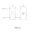
- FIG. 1 illustrates the structure of a chameleon filter according to an embodiment of the present invention.
- a 3-dB hybrid coupler 110 is connected to a filter unit 120 in the chameleon filter according to the embodiment of the present invention. That is, the filter of the present invention is configured so that a first port of the hybrid coupler 110 serves as an input port of the chameleon filter, a fourth port of the hybrid coupler 110 serves as an output port of the chameleon filter, a second port of the hybrid coupler 110 is connected to a first port (e.g. an input port) of the filter unit 120, and a third port of the hybrid coupler 110 is connected to a second port (e.g. an output port) of the filter unit 120.
- the filter unit 120 may be configured with various types of filters such as a BPF, BRF, High Pass Filter (HPF), LPF, etc. If the filter unit 120 is configured with a BPF, the chameleon filter has BRF characteristics.
- FIG. 5A illustrates the waveforms of a signal S 21 passed through the general BPF and a signal S 11 returned from the general BPF.
- FIG. 5B illustrates the waveforms of signals in the chameleon filter of the present invention in which the hybrid coupler 110 is combined with the filter unit 120 configured with a BPF in an RF system.
- the phases of the passed signal S 21 and the returned signal S 11 are inverted in FIG. 5B . Therefore, although the filter unit 120 is configured with a BPF in the chameleon filter of the present invention, its overall characteristics are BRF characteristics.
- a hybrid coupler generally functions to equally divide signal power with a phase difference of 90 degrees. For example, when a signal is input to the first port of the hybrid coupler 110, the power of the signal is equally divided into two parts with a 90-degree phase difference and then provided to the first and second ports of the filter unit 120 through the second port (0 degrees) and the third port (-90 degrees) of the hybrid coupler 110. Signals in the pass band of the filter unit 120 pass through the filter unit 120 and are fed back to the opposite ports, that is, the third and second ports of the hybrid coupler 110. Then the signals are combined due to the phase difference and output to the first port of the hybrid coupler 110, with no signal output to the fourth port of the hybrid coupler 110.
- signals outside the pass band of the filter unit 120 do not pass through the filter unit 120, return from the first and second ports of the filter unit 120, and then are fed back to the second and third ports of the hybrid coupler 110, respectively. These signals are combined due to the phase difference and output to the fourth port of the hybrid coupler 110.
- a signal of the pass band of the filter unit 120 in a signal input to the input port of the chameleon filter i.e. the first port of the hybrid coupler
- a signal outside the pass band of the filter unit 120 in the input signal is output to the output port of the chameleon filter (i.e. the fourth port of the hybrid coupler) in the whole filter structure.
- Parts that divide/combine the power of signals according to their phase difference include a hybrid ring, a branchline directional coupler, a 3-dB directional coupler, a magic T, etc. If such a part is used instead of the hybrid coupler 110, it may be configured so as to adjust the phase of a signal using a phase shifter additionally. For example, if a magic T substitutes for the hybrid coupler 110, a phase shifter is provided on a connection path between a second port (or third port) of the magic T and the filter unit, to thereby shift the phase of a passed signal by 90 degrees.
- the chameleon filter having the above configuration according to the present invention is designed to operate as a BRF on the whole, that is, in a 'hybrid coupler+BPF' structure, it is more useful. That is, a typical BRF is designed by connecting resonators with one another via a 50-ohm ( ⁇ ) line. This structure requires a relatively large size and is complex. In addition, since much coupling does not occur between resonators, the BRF has limitations in rejecting a frequency band having a predetermined or wider bandwidth. In contrast, the chameleon filter of the present invention is relatively easily implemented and facilitates realization of a BRF using a BPF structure that can process a wide frequency band. The chameleon filter of the present invention can remarkably reduce path loss that may be caused as the total length of the 50-ohm line increases.
- the 50-ohm line should be lengthened or shortened with respect to a corresponding frequency in order to achieve notch characteristics in the general BRF.
- the chameleon filter of the present invention realizes notch characteristics in the BPF and thus implements the BRF on the whole using the notch characteristics. Hence, the notch characteristics of the BRF are easily achieved and skirt characteristics can be improved.
- the chameleon filter of the present invention can realize an HPF structure on the whole using an LPF structure.
- an HPF which is relatively difficult to fabricate can be easily implemented.
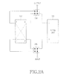
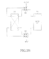
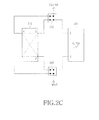
- FIGs. 2A to 2D illustrate the structure of a chameleon filter according to another embodiment of the present invention.
- the chameleon filter according to the second embodiment of the present invention includes a hybrid coupler 210, a filter unit 220, and first and second switch units 240 and 230.
- the hybrid coupler 210 and the filter unit 220 may be identical to their counterparts in the embodiment illustrated in FIG. 1 .
- the first and second switch units 240 and 230 each may have a combination of general single on/off switches, or a combination of a Double Pole Double Throw (DPDT) switch and a general single on/off switch, which establishes a signal connection path dynamically according to an external switching control signal so that the input and output ports of the chameleon filter are connected directly to the filter unit ( FIG. 2A ), the input and output ports of the chameleon filter are connected to the filter unit indirectly via the hybrid coupler 210 ( FIG. 2B ), a signal passes through the hybrid coupler 210 ( FIG. 2C ), and a signal bypasses the hybrid coupler 210 and the filter unit 220 ( FIG. 2D ).
- DPDT Double Pole Double Throw
- FIG. 2A illustrates the structure of a chameleon filter according to the present invention, when the chameleon filter operates as a BPF
- FIG. 2B illustrates the structure of a chameleon filter according to the present invention, when the chameleon filter operates as a BRF.
- the chameleon filter of the present invention operates as a BPF
- the signal is output to an output port through the filter unit 220 configured with a BPF and the second switch unit 230. Therefore, there is no signal input and output to and from the hybrid coupler 210 and the chameleon filter of the present invention is used to pass a predetermined frequency band.
- the first and second switch units 240 and 230 switch in a different manner from in FIG. 2A , such that a path is established to pass input and output signals through the hybrid coupler 210.
- the signal When a signal is input to the input port of the first switch unit 240, the signal is provided to a first port of the hybrid coupler 210, equally divided into two signals each having a half power with a phase difference of 90 degrees, and then output through second and third ports of the hybrid coupler 210. Signals of the pass band of the filter unit 220 in the divided two signals pass through the filter unit 220 and the first and second switches 240 and 230, whereas signals outside the pass band of the filter unit 220 in the divided two signals are reflected from the filter unit 220 and fed back to the second and third ports of the hybrid coupler 210. Signals of the pass band of the filter unit 220 in these input signals are output through the fourth port of the hybrid coupler 210. The signals output from the fourth port of the hybrid coupler 210 are output to the output port via the second switch 230.
- an input signal is input only to the hybrid coupler 210.
- the input signal bypasses the filter unit 220.
- a signal input to the first port of the hybrid coupler 210 is divided into two signals each having an equal half power, with a phase difference of 90 degrees.
- the divided signals are output through the second and third ports of the hybrid coupler 210, fully reflected from the first and second switches 240 and 230, and then fed back to the second and third ports of the hybrid coupler 210.
- These signals are combined due to the phase difference and then output through the fourth port of the hybrid coupler 210.
- the signal output from the fourth port of the hybrid coupler 210 is just output through the second switch 230.
- the structure illustrated in FIG. 2C simply outputs an input signal without any signal processing.
- the input signal bypasses the filter unit 220 without being filtered.
- a signal bypasses the filter unit 220.
- a signal input to the input port of the first switch 240 bypasses the filter unit 220 or the hybrid coupler 210 in a bypass path and is output to the output port via the second switch 230.
- the filter of the present invention may be appropriate for a wireless communication system in which filter is not required in an initial use environment and then required in a subsequent use environment.
- a mobile communication BS system should return a part of a used frequency band on a service provider basis. For example, a specific service provider may use 800 to 825MHz in a current year and then may use only 810 to 825MHz in the next year. That is, the service provider should return the frequency band from 800MHz to below 810MHz.
- the service provider should install a BRF that rejects the frequency band from 800MHz to below 810MHz or a BPF that passes only 810 to 825MHz in every BS. It is almost impossible to simultaneously install the filters in all BSs distributed nationwide. Therefore, the filters are sequentially installed in the BSs over a relative long period (e.g. 6 months) before the next year.
- BSs in which filters are installed early cannot service the frequency band from 800MHz to below 810MHz.
- use of the filter according to the present invention enables signal bypassing despite the preliminary filter installation in the BS.
- an entire serviceable band can be used in the current year.
- signals pass through the filters through switching control of the filters in the BSs so that the service band of all BSs may be changed to 810 to 825MHz almost simultaneously.
- FIGs. 2A to 2D have been described in the context of the filter unit 220 being a BPF, it is clearly understood that the BPF may be replaced with another filter such as a BRF, an HPF, an LPF, etc.
- FIG. 3 illustrates the structure of a chameleon filter according to a third embodiment of the present invention.
- the chameleon filter according to the third embodiment of the present invention includes a hybrid coupler 310 and a filter unit 320. While the filter units may be configured with a single filter in the first and second embodiments of the present invention, the filter unit 320 includes at least two identical filters, that is, first and second filters 3210 and 3220. The filter unit 320 further includes a phase shifter 3230.
- the chameleon filter according to the third embodiment of the present invention is configured such that a first port of the hybrid coupler 310 serves as an input port of the chameleon filter, a fourth port of the hybrid coupler 310 serves as an output port of the chameleon filter, a second port of the hybrid coupler 310 is connected to a first port (e.g. an input port) of the first filter 3210, and a third port of the hybrid coupler 310 is connected to a first port (e.g. an input port) of the second filter 3220.
- a second port (e.g. an output port) of the first filter 3210 is opened and a second port (e.g. an output port) of the second filter 3220 is connected to an end of the phase shifter 3230. The other end of the phase shifter 3230 is opened.
- a signal input to the hybrid coupler 310 through the first port is equally divided into two signals each having a half power, with a phase difference of 90 degrees and output through the second and third ports of the hybrid coupler 310.
- Signals of the pass bands of the first and second filters 3210 and 3220 in the output signals are input to the first and second filters 3210 and 3220 and signals outside the pass bands of the first and second filters 3210 and 3220 are reflected from the first and second filters 3210 and 3220.
- the first and second filters 3210 and 3220 may be the same types of filters, such as BPFs, BRFs, HPFs, LPFs, etc.
- Signals outside the pass bands of the first and second filter 3210 and 3220 are reflected from the first and second filter 3210 and 3220, fed back to the second and third ports of the hybrid coupler 310, and then output through the fourth port of the hybrid coupler 310.
- the phase variation of a signal of the pass band passed through the second filter 3220 can be adjusted dynamically.
- the signal in the pass band of the second filter 3220 is phase-shifted in the phase shifter 3230, reflected from the open port of the phase shifter 3230, and fed back to the third port of the hybrid coupler 310 through the second filter 3220.
- the signal in the pass band of the first filter 3210 is reflected from the open port of the first filter 3210 and fed back to the second port of the hybrid coupler 310.
- the phase difference between the signals is not accurately 90 degrees. Consequently, the signals are divided into the first and fourth ports of the hybrid coupler 310 according to the phase difference.
- the chameleon filter operates as a BRF on the whole and the loss bandwidth (dB) of a signal in a rejection band of the chameleon filter is changed according to a phase variation controlled by the phase shifter 3230.
- This chameleon filter is applicable to a system in which the rejected amount of a signal in a rejection band needs to be adjusted.
- FIG. 4 illustrates the structure of a chameleon filter according to a fourth embodiment of the present invention.
- the chameleon filter according to the fourth embodiment of the present invention includes a first filter unit 420, a hybrid coupler 410, and a second filter unit 430 and has a low signal loss equal to or smaller than a predetermined threshold.
- the chameleon filter is similar to the chameleon filter according to the first embodiment, except that the second filter unit 430 is further installed between a fourth port of the hybrid coupler 410 and an output port of the chameleon filter.
- the number of resonators may differ for the first and second filter units 420 and 430.
- the second filter unit 430 may be configured with a 6-stage BPF and the first filter unit 420 may be configured with a 4-stage BPF.
- the hybrid coupler 410 and the first filter unit 420 in combination may create BRF characteristics. That is, the chameleon filter according to the fourth embodiment of the present invention is a combination of a BPF structure and a BRF structure. If the rejection band of the BRF structure is positioned at one band edge of the BPF, this structure may have less signal loss and similar or improved characteristics of one band edge, for example, compared to a 10-stage BPF structure.
- first and second filter units 420 and 430 may be replaced with various filters other than BPFs, such as BRFs, HPFs, LPFs, etc. While it has been described in FIGs. 1 to 4 that the chameleon filters are configured with filters (i.e. indicated by reference numerals 120, 220, 320, 330, 410 and 430), other mobile communication parts may be used instead of the filters 120, 220, 320, 330, 410 and 430, to thereby achieve a similar function to the function of a chameleon filter.
Landscapes
- Control Of Motors That Do Not Use Commutators (AREA)
Abstract
Description
- The present invention relates to a Radio Frequency (RF) filter.
- A filter is an essential part of an RF system, for passing or rejecting a predetermined frequency band. Filters are classified into Band Pass Filters (BPFs), Band Rejection Filters (BRFs), High Pass Filters (HPFs), Low Pass Filters (LPFs), etc. Such filters are designed so as to satisfy frequency pass or rejection characteristics required for the RF system. Once the filters are installed, their characteristics are difficult to change unless they are replaced. For example, when a BRF is to be reinstalled in an RF system equipped with a BPF, the BPF should be removed and then replaced with the BRF. The filter replacement may lead to communication disconnection and increase cost.
- Meanwhile, the BRF is designed by connecting resonators using a 50-ohm (Ω) line. In this case, since no coupling occurs between resonators, a frequency band equal to or wider than a predetermined bandwidth cannot be rejected. In addition, as the number of resonators increases, the total length of the 50-ohm line also increases, thereby increasing path loss. Another shortcoming of the BRF is that a low or high frequency band is selectively rejected with respect to a specific frequency and thus it is difficult to improve band edge characteristics.
- An aspect of embodiments of the present invention is to address at least the problems and/or disadvantages and to provide at least the advantages described below. Accordingly, an aspect of embodiments of the present invention is to provide an RF filter for decreasing path loss.
- Another aspect of embodiments of the present invention provides an RF filter for improving band edge characteristics.
- Another aspect of embodiments of the present invention provides an RF filter for inverting a signal characteristic easily.
- Another aspect of embodiments of the present invention provides an RF filter for rejecting a wide frequency band by increasing coupling between resonators.
- A further aspect of embodiments of the present invention provides an RF filter for facilitating design of notch characteristics.
- In accordance with an aspect of embodiments of the present invention, there is provided an RF filter in which a coupler receives an input signal through a first port, divides the input signal, outputs the divided signals through second and third ports, combines signals received through the second and third ports according to phases of the signals, and outputs the combined signal through the first port or as an output signal of the RF filter through a fourth port, and a first filter unit has a first port connected to the second port of the coupler and a second port connected to the third port of the coupler, for having a predetermined frequency filtering characteristic.
- As is apparent from the above description of the embodiments of the present invention, because the present invention provides a new filter by combining a filter with a hybrid coupler, it can reduce the path loss of a signal, improve band edge characteristics, easily invert signal characteristics, reject a wide frequency band by increasing coupling between resonators, and facilitate design of notch characteristics.
-
-
FIG. 1 schematically illustrates the structure of a chameleon filter according to an embodiment of the present invention; -
FIGs. 2A to 2D schematically illustrate the structure of a chameleon filter according to another embodiment of the present invention; -
FIG. 3 schematically illustrates the structure of a chameleon filter according to a third embodiment of the present invention; -
FIG. 4 schematically illustrates the structure of a chameleon filter according to a fourth embodiment of the present invention; and -
FIGs. 5A and 5B are diagrams illustrating the waveforms of signals in a general filter and a chameleon filter. - Now, a preferred embodiment of the present invention will be described with reference to the attached drawings. While specific details such as components are described in the following description, they are given to help comprehensive understanding of the present invention. Therefore, it is clearly to be understood to those skilled in the art that changes or modifications can be made to the present invention within the scope and spirit of the present invention.
- The following description is given of a so-called chameleon filter which is configured by combining a hybrid coupler with a filter and thus has new characteristics modified from original characteristics. For example, a Band Pass Filter (BPF) and a hybrid coupler may be combined into a chameleon Band Rejection Filter (BRF) and a Low Pass Filter (LPF) and a hybrid coupler may be combined into a chameleon HPF, or vice versa in the present invention.
- Now, the present invention will be described in detail with the attached drawings.
-
FIG. 1 illustrates the structure of a chameleon filter according to an embodiment of the present invention. - Referring to
FIG. 1 , a 3-dB hybrid coupler 110 is connected to afilter unit 120 in the chameleon filter according to the embodiment of the present invention. That is, the filter of the present invention is configured so that a first port of thehybrid coupler 110 serves as an input port of the chameleon filter, a fourth port of thehybrid coupler 110 serves as an output port of the chameleon filter, a second port of thehybrid coupler 110 is connected to a first port (e.g. an input port) of thefilter unit 120, and a third port of thehybrid coupler 110 is connected to a second port (e.g. an output port) of thefilter unit 120. Thefilter unit 120 may be configured with various types of filters such as a BPF, BRF, High Pass Filter (HPF), LPF, etc. If thefilter unit 120 is configured with a BPF, the chameleon filter has BRF characteristics. - Characteristics of the
filter unit 120 will be described with reference toFIGs. 5A and 5B , when thefilter unit 120 is configured with a BPF.FIG. 5A illustrates the waveforms of a signal S21 passed through the general BPF and a signal S11 returned from the general BPF.FIG. 5B illustrates the waveforms of signals in the chameleon filter of the present invention in which thehybrid coupler 110 is combined with thefilter unit 120 configured with a BPF in an RF system. Compared toFIG. 5A , the phases of the passed signal S21 and the returned signal S11 are inverted inFIG. 5B . Therefore, although thefilter unit 120 is configured with a BPF in the chameleon filter of the present invention, its overall characteristics are BRF characteristics. - More specifically, a hybrid coupler generally functions to equally divide signal power with a phase difference of 90 degrees. For example, when a signal is input to the first port of the
hybrid coupler 110, the power of the signal is equally divided into two parts with a 90-degree phase difference and then provided to the first and second ports of thefilter unit 120 through the second port (0 degrees) and the third port (-90 degrees) of thehybrid coupler 110. Signals in the pass band of thefilter unit 120 pass through thefilter unit 120 and are fed back to the opposite ports, that is, the third and second ports of thehybrid coupler 110. Then the signals are combined due to the phase difference and output to the first port of thehybrid coupler 110, with no signal output to the fourth port of thehybrid coupler 110. Meanwhile, signals outside the pass band of thefilter unit 120 do not pass through thefilter unit 120, return from the first and second ports of thefilter unit 120, and then are fed back to the second and third ports of thehybrid coupler 110, respectively. These signals are combined due to the phase difference and output to the fourth port of thehybrid coupler 110. - In conclusion, a signal of the pass band of the
filter unit 120 in a signal input to the input port of the chameleon filter (i.e. the first port of the hybrid coupler) is reflected to the input port of the chameleon filter, whereas a signal outside the pass band of thefilter unit 120 in the input signal is output to the output port of the chameleon filter (i.e. the fourth port of the hybrid coupler) in the whole filter structure. - Parts that divide/combine the power of signals according to their phase difference include a hybrid ring, a branchline directional coupler, a 3-dB directional coupler, a magic T, etc. If such a part is used instead of the
hybrid coupler 110, it may be configured so as to adjust the phase of a signal using a phase shifter additionally. For example, if a magic T substitutes for thehybrid coupler 110, a phase shifter is provided on a connection path between a second port (or third port) of the magic T and the filter unit, to thereby shift the phase of a passed signal by 90 degrees. - If the chameleon filter having the above configuration according to the present invention is designed to operate as a BRF on the whole, that is, in a 'hybrid coupler+BPF' structure, it is more useful. That is, a typical BRF is designed by connecting resonators with one another via a 50-ohm (Ω) line. This structure requires a relatively large size and is complex. In addition, since much coupling does not occur between resonators, the BRF has limitations in rejecting a frequency band having a predetermined or wider bandwidth. In contrast, the chameleon filter of the present invention is relatively easily implemented and facilitates realization of a BRF using a BPF structure that can process a wide frequency band. The chameleon filter of the present invention can remarkably reduce path loss that may be caused as the total length of the 50-ohm line increases.
- Further, the 50-ohm line should be lengthened or shortened with respect to a corresponding frequency in order to achieve notch characteristics in the general BRF. Thus it is difficult to achieve notch characteristics with the general BRF. However, the chameleon filter of the present invention realizes notch characteristics in the BPF and thus implements the BRF on the whole using the notch characteristics. Hence, the notch characteristics of the BRF are easily achieved and skirt characteristics can be improved.
- Similarly, the chameleon filter of the present invention can realize an HPF structure on the whole using an LPF structure. In this case, an HPF which is relatively difficult to fabricate can be easily implemented.
-
FIGs. 2A to 2D illustrate the structure of a chameleon filter according to another embodiment of the present invention. Referring toFIGs. 2A to 2D , the chameleon filter according to the second embodiment of the present invention includes ahybrid coupler 210, afilter unit 220, and first andsecond switch units hybrid coupler 210 and thefilter unit 220 may be identical to their counterparts in the embodiment illustrated inFIG. 1 . The first andsecond switch units FIG. 2A ), the input and output ports of the chameleon filter are connected to the filter unit indirectly via the hybrid coupler 210 (FIG. 2B ), a signal passes through the hybrid coupler 210 (FIG. 2C ), and a signal bypasses thehybrid coupler 210 and the filter unit 220 (FIG. 2D ). Hereinbelow, with reference toFIGs. 2A and2B , the structure and operation of thefilter unit 220 will be described in detail, in the case where thefilter unit 220 is configured with a BPF. -
FIG. 2A illustrates the structure of a chameleon filter according to the present invention, when the chameleon filter operates as a BPF andFIG. 2B illustrates the structure of a chameleon filter according to the present invention, when the chameleon filter operates as a BRF. - Referring to
FIG. 2A , in the case where the chameleon filter of the present invention operates as a BPF, when a signal is input to an input port of thefirst switch unit 240, the signal is output to an output port through thefilter unit 220 configured with a BPF and thesecond switch unit 230. Therefore, there is no signal input and output to and from thehybrid coupler 210 and the chameleon filter of the present invention is used to pass a predetermined frequency band. - Referring to
FIG. 2B , in the case where the chameleon filter of the present invention operates as a BRF, the first andsecond switch units FIG. 2A , such that a path is established to pass input and output signals through thehybrid coupler 210. - When a signal is input to the input port of the
first switch unit 240, the signal is provided to a first port of thehybrid coupler 210, equally divided into two signals each having a half power with a phase difference of 90 degrees, and then output through second and third ports of thehybrid coupler 210. Signals of the pass band of thefilter unit 220 in the divided two signals pass through thefilter unit 220 and the first andsecond switches filter unit 220 in the divided two signals are reflected from thefilter unit 220 and fed back to the second and third ports of thehybrid coupler 210. Signals of the pass band of thefilter unit 220 in these input signals are output through the fourth port of thehybrid coupler 210. The signals output from the fourth port of thehybrid coupler 210 are output to the output port via thesecond switch 230. - Referring to
FIG. 2C , an input signal is input only to thehybrid coupler 210. In this structure, the input signal bypasses thefilter unit 220. - More specifically, a signal input to the first port of the
hybrid coupler 210 is divided into two signals each having an equal half power, with a phase difference of 90 degrees. The divided signals are output through the second and third ports of thehybrid coupler 210, fully reflected from the first andsecond switches hybrid coupler 210. These signals are combined due to the phase difference and then output through the fourth port of thehybrid coupler 210. The signal output from the fourth port of thehybrid coupler 210 is just output through thesecond switch 230. - The structure illustrated in
FIG. 2C simply outputs an input signal without any signal processing. Thus the input signal bypasses thefilter unit 220 without being filtered. - Like the structure illustrated in
FIG. 2C , a signal bypasses thefilter unit 220. A signal input to the input port of thefirst switch 240 bypasses thefilter unit 220 or thehybrid coupler 210 in a bypass path and is output to the output port via thesecond switch 230. - As illustrated in
FIGs. 2C and2D , the filter of the present invention may be appropriate for a wireless communication system in which filter is not required in an initial use environment and then required in a subsequent use environment. - For example, it may occur that a mobile communication BS system should return a part of a used frequency band on a service provider basis. For example, a specific service provider may use 800 to 825MHz in a current year and then may use only 810 to 825MHz in the next year. That is, the service provider should return the frequency band from 800MHz to below 810MHz.
- In this case, the service provider should install a BRF that rejects the frequency band from 800MHz to below 810MHz or a BPF that passes only 810 to 825MHz in every BS. It is almost impossible to simultaneously install the filters in all BSs distributed nationwide. Therefore, the filters are sequentially installed in the BSs over a relative long period (e.g. 6 months) before the next year.
- However, BSs in which filters are installed early cannot service the frequency band from 800MHz to below 810MHz. In this case, use of the filter according to the present invention enables signal bypassing despite the preliminary filter installation in the BS. Thus an entire serviceable band can be used in the current year. In the next year, signals pass through the filters through switching control of the filters in the BSs so that the service band of all BSs may be changed to 810 to 825MHz almost simultaneously.
- While
FIGs. 2A to 2D have been described in the context of thefilter unit 220 being a BPF, it is clearly understood that the BPF may be replaced with another filter such as a BRF, an HPF, an LPF, etc. -
FIG. 3 illustrates the structure of a chameleon filter according to a third embodiment of the present invention. - Referring to
FIG. 3 , the chameleon filter according to the third embodiment of the present invention includes ahybrid coupler 310 and afilter unit 320. While the filter units may be configured with a single filter in the first and second embodiments of the present invention, thefilter unit 320 includes at least two identical filters, that is, first andsecond filters filter unit 320 further includes aphase shifter 3230. More specifically, the chameleon filter according to the third embodiment of the present invention is configured such that a first port of thehybrid coupler 310 serves as an input port of the chameleon filter, a fourth port of thehybrid coupler 310 serves as an output port of the chameleon filter, a second port of thehybrid coupler 310 is connected to a first port (e.g. an input port) of thefirst filter 3210, and a third port of thehybrid coupler 310 is connected to a first port (e.g. an input port) of thesecond filter 3220. In addition, a second port (e.g. an output port) of thefirst filter 3210 is opened and a second port (e.g. an output port) of thesecond filter 3220 is connected to an end of thephase shifter 3230. The other end of thephase shifter 3230 is opened. - A signal input to the
hybrid coupler 310 through the first port is equally divided into two signals each having a half power, with a phase difference of 90 degrees and output through the second and third ports of thehybrid coupler 310. Signals of the pass bands of the first andsecond filters second filters second filters second filters second filters - Signals outside the pass bands of the first and
second filter second filter hybrid coupler 310, and then output through the fourth port of thehybrid coupler 310. - Meanwhile, since the second port of the
second filter 3220 is connected to thephase shifter 3230, the phase variation of a signal of the pass band passed through thesecond filter 3220 can be adjusted dynamically. Hence, the signal in the pass band of thesecond filter 3220 is phase-shifted in thephase shifter 3230, reflected from the open port of thephase shifter 3230, and fed back to the third port of thehybrid coupler 310 through thesecond filter 3220. The signal in the pass band of thefirst filter 3210 is reflected from the open port of thefirst filter 3210 and fed back to the second port of thehybrid coupler 310. If the signal whose phase variation was not adjusted (the signal input from the first filter 3210) and the signal whose variation was adjusted (the signal input from the second filter 3220) are input to thehybrid coupler 310 through the second and third ports of thehybrid coupler 310, respectively, the phase difference between the signals is not accurately 90 degrees. Consequently, the signals are divided into the first and fourth ports of thehybrid coupler 310 according to the phase difference. - It can be concluded that parts of signals in the pass bands of the first and
second filters hybrid coupler 310 according to the phase variation adjusted by thephase shifter 3230 in the chameleon filter according to the third embodiment of the present invention, illustrated inFIG. 3 . For example, if the first andsecond filters phase shifter 3230. This chameleon filter is applicable to a system in which the rejected amount of a signal in a rejection band needs to be adjusted. -
FIG. 4 illustrates the structure of a chameleon filter according to a fourth embodiment of the present invention. - Referring to
FIG. 4 , the chameleon filter according to the fourth embodiment of the present invention includes afirst filter unit 420, ahybrid coupler 410, and asecond filter unit 430 and has a low signal loss equal to or smaller than a predetermined threshold. The chameleon filter is similar to the chameleon filter according to the first embodiment, except that thesecond filter unit 430 is further installed between a fourth port of thehybrid coupler 410 and an output port of the chameleon filter. The number of resonators may differ for the first andsecond filter units second filter unit 430 may be configured with a 6-stage BPF and thefirst filter unit 420 may be configured with a 4-stage BPF. In this case, thehybrid coupler 410 and thefirst filter unit 420 in combination may create BRF characteristics. That is, the chameleon filter according to the fourth embodiment of the present invention is a combination of a BPF structure and a BRF structure. If the rejection band of the BRF structure is positioned at one band edge of the BPF, this structure may have less signal loss and similar or improved characteristics of one band edge, for example, compared to a 10-stage BPF structure. - It is clear also in
FIG. 4 that the first andsecond filter units FIGs. 1 to 4 that the chameleon filters are configured with filters (i.e. indicated byreference numerals filters - While embodiments have been shown and described with reference to the drawings, it will be understood by those skilled in the art that various changes in form and details may be made therein without departing from the spirit and scope of the inventive concept as defined by the appended claims.
Claims (15)
- A Radio Frequency (RF) filter comprising:a coupler for receiving an input signal through a first port, dividing the input signal, outputting the divided signals through second and third ports, combining signals received through the second and third ports according to phases of the signals, and outputting the combined signal through the first port or as an output signal of the RF filter through a fourth port; anda first filter unit having a first port connected to the second port of the coupler and a second port connected to the third port of the coupler, for having a predetermined frequency filtering characteristic.
- The RF filter of claim 1, wherein if the RF filter requires a Band Pass Filter (BPF) characteristic on the whole, the first filter unit includes a Band Rejection Filter (BRF), if the RF filter requires a BRF characteristic on the whole, the first filter unit includes a BPF, if the RF filter requires a High Pass Filter (HPF) characteristic on the whole, the first filter unit includes a Low Pass Filter (LPF), and if the RF filter requires an LPF characteristic on the whole, the first filter unit includes an HPF.
- The RF filter of claim 1, further comprising first and second switch units for dynamically establishing a signal path according to an external switching control signal so that input and output ports of the RF filter are connected to the first filter unit directly or indirectly via the coupler, a signal passes only though the coupler, or a signal bypasses the first filter unit and the coupler.
- The RF filter of claim 3, wherein each of the first and second switch units has a combination of single on/off switches or a combination of a Double Pole Double Throw (DPDT) switch and single on/off switches.
- The RF filter of claim 1, further comprising a second filter unit connected to the fourth port of the coupler, for outputting an output signal of the RF filter.
- The RF filter of claim 5, wherein each of the first and second filter units includes a BPF having a predetermined number of stages.
- The RF filter of any of claims 1 to 6, wherein the coupler is a hybrid coupler.
- The RF filter of any of claims 1 to 6, wherein the coupler is a magic T, further comprising a phase shifter provided on a path between the second port of the coupler and the first port of the first filter unit or between the third port of the coupler and the second port of the first filter unit, for shifting a phase of a passed signal by 90 degrees.
- The RF filter of claim 1, wherein the first filter unit comprises:a first filter having one end connected to the first port of the first filter unit and the other end that is opened;a second filter having one end connected to the second port of the first filter unit; anda phase shifter having one end connected to the other end of the second filter and the other end that is opened.
- The RF filter of claim 9, wherein if the RF filter requires a BPF characteristic on the whole, the first and second filters of the first filter are BRFs, if the RF filter requires a BRF characteristic on the whole, the first and second filters of the first filter unit are BPFs, if the RF filter requires an HPF characteristic on the whole, the first and second filters of the first filter unit are LPFs, and if the RF filter requires an LPF characteristic on the whole, the first and second filters of the first filter unit are HPFs.
- The RF filter of claim 9, further comprising first and second switch units for dynamically establishing a signal path according to an external switching control signal so that input and output ports of the RF filter are connected to the first filter unit directly or indirectly via the coupler, a signal passes only though the coupler, or a signal bypasses the first filter unit and the coupler.
- The RF filter of claim 11, wherein each of the first and second switch units has a combination of single on/off switches or a combination of a Double Pole Double Throw (DPDT) switch and single on/off switches.
- The RF filter of claim 9, further comprising a second filter unit connected to the fourth port of the coupler, for outputting an output signal of the RF filter.
- The RF filter of any of claims 9 to 13, wherein the coupler is a hybrid coupler.
- The RF filter of any of claims 9 to 13, wherein the coupler is a magic T, further comprising a phase shifter provided on a path between the second port of the coupler and the first port of the first filter unit or between the third port of the coupler and the second port of the first filter unit, for shifting a phase of a passed signal by 90 degrees.
Priority Applications (1)
| Application Number | Priority Date | Filing Date | Title |
|---|---|---|---|
| EP15150944.5A EP2884578B1 (en) | 2009-11-02 | 2010-11-02 | Radio frequency filter |
Applications Claiming Priority (2)
| Application Number | Priority Date | Filing Date | Title |
|---|---|---|---|
| US25710209P | 2009-11-02 | 2009-11-02 | |
| PCT/KR2010/007677 WO2011053099A2 (en) | 2009-11-02 | 2010-11-02 | Radio frequency filter |
Related Child Applications (2)
| Application Number | Title | Priority Date | Filing Date |
|---|---|---|---|
| EP15150944.5A Division EP2884578B1 (en) | 2009-11-02 | 2010-11-02 | Radio frequency filter |
| EP15150944.5A Division-Into EP2884578B1 (en) | 2009-11-02 | 2010-11-02 | Radio frequency filter |
Publications (3)
| Publication Number | Publication Date |
|---|---|
| EP2498331A2 true EP2498331A2 (en) | 2012-09-12 |
| EP2498331A4 EP2498331A4 (en) | 2013-05-15 |
| EP2498331B1 EP2498331B1 (en) | 2015-04-15 |
Family
ID=43922919
Family Applications (2)
| Application Number | Title | Priority Date | Filing Date |
|---|---|---|---|
| EP10827183.4A Active EP2498331B1 (en) | 2009-11-02 | 2010-11-02 | Radio frequency filter |
| EP15150944.5A Active EP2884578B1 (en) | 2009-11-02 | 2010-11-02 | Radio frequency filter |
Family Applications After (1)
| Application Number | Title | Priority Date | Filing Date |
|---|---|---|---|
| EP15150944.5A Active EP2884578B1 (en) | 2009-11-02 | 2010-11-02 | Radio frequency filter |
Country Status (6)
| Country | Link |
|---|---|
| US (2) | US8749321B2 (en) |
| EP (2) | EP2498331B1 (en) |
| JP (1) | JP5493002B2 (en) |
| KR (1) | KR101756116B1 (en) |
| CN (2) | CN104966864B (en) |
| WO (1) | WO2011053099A2 (en) |
Families Citing this family (28)
| Publication number | Priority date | Publication date | Assignee | Title |
|---|---|---|---|---|
| KR101859230B1 (en) * | 2011-12-26 | 2018-05-18 | 한국전자통신연구원 | RF front-end apparatus using RF passive elements in wireless communication systems |
| KR101545139B1 (en) * | 2012-10-19 | 2015-08-20 | 한국전기연구원 | Method of phase tracking of power system using LPN filter |
| US9490866B2 (en) | 2012-12-11 | 2016-11-08 | University Of Southern California | Passive leakage cancellation networks for duplexers and coexisting wireless communication systems |
| US9425840B2 (en) * | 2013-04-26 | 2016-08-23 | Northrop Grumman Systems Corporation | Wideband tunable notch cancellation |
| US9935670B2 (en) | 2013-09-26 | 2018-04-03 | Qorvo Us, Inc. | Carrier aggregation using multiple antennas |
| US9985682B2 (en) | 2013-10-24 | 2018-05-29 | Qorvo Us, Inc. | Broadband isolation low-loss ISM/MB-HB tunable diplexer |
| US9899986B2 (en) * | 2013-10-24 | 2018-02-20 | Qoro US, Inc. | RF diplexer |
| WO2015089091A1 (en) | 2013-12-10 | 2015-06-18 | University Of Southern California | Enhancing isolation and impedance matching in hybrid-based cancellation networks and duplexers |
| US10615949B2 (en) | 2014-02-14 | 2020-04-07 | University Of Southern California | Hybrid-based cancellation in presence of antenna mismatch |
| WO2015123586A1 (en) * | 2014-02-14 | 2015-08-20 | University Of Southern California | Reflection and hybrid reflection filters |
| US9871543B2 (en) * | 2014-02-19 | 2018-01-16 | University Of Southern California | Miniature acoustic resonator-based filters and duplexers with cancellation methodology |
| JP6539119B2 (en) * | 2014-06-13 | 2019-07-03 | 住友電気工業株式会社 | Electronic device |
| JP2016066884A (en) * | 2014-09-24 | 2016-04-28 | 住友電気工業株式会社 | Filter device |
| US9941908B2 (en) | 2014-10-20 | 2018-04-10 | Infineon Technologies Ag | System and method for a radio frequency filter |
| US9866201B2 (en) | 2015-09-08 | 2018-01-09 | Abtum Inc. | All-acoustic duplexers using directional couplers |
| US9762416B2 (en) | 2015-09-08 | 2017-09-12 | Abtum Inc. | Reflection coefficient reader |
| US9912326B2 (en) | 2015-09-08 | 2018-03-06 | Abtum Inc. | Method for tuning feed-forward canceller |
| US10581650B2 (en) | 2015-09-08 | 2020-03-03 | Qorvo Us, Inc. | Enhancing isolation in radio frequency multiplexers |
| WO2017053875A1 (en) * | 2015-09-23 | 2017-03-30 | The Government Of The United States Of America, As Represented By The Secretary Of The Navy | Switched bandstop filter with low-loss linear-phase bypass state |
| US9755668B2 (en) | 2015-09-30 | 2017-09-05 | Abtum Inc. | Radio frequency complex reflection coefficient reader |
| US10038458B2 (en) | 2015-10-06 | 2018-07-31 | Abtum Inc. | Reflection-based radio-frequency multiplexers |
| CN108352915B (en) | 2015-10-12 | 2020-06-30 | Qorvo美国公司 | Radio frequency multiplexer based on hybrid coupler |
| US10373794B2 (en) | 2015-10-29 | 2019-08-06 | Lam Research Corporation | Systems and methods for filtering radio frequencies from a signal of a thermocouple and controlling a temperature of an electrode in a plasma chamber |
| WO2018057725A1 (en) | 2016-09-21 | 2018-03-29 | Abtum Inc. | Enhancing isolation in hybrid-based radio frequency duplexers and multiplexers |
| US10181833B2 (en) * | 2017-03-16 | 2019-01-15 | Infineon Technologies Ag | Reflection type phase shifter with active device tuning |
| JP2020098969A (en) * | 2018-12-17 | 2020-06-25 | 株式会社村田製作所 | Filter circuit using 90° hybrid coupler |
| US12062827B2 (en) * | 2018-12-28 | 2024-08-13 | Google Llc | Attenuator for qubit drive signals |
| CN111970727A (en) * | 2020-07-15 | 2020-11-20 | 国家无线电监测中心检测中心 | NB-IoT base station blocking test system |
Family Cites Families (24)
| Publication number | Priority date | Publication date | Assignee | Title |
|---|---|---|---|---|
| US3435384A (en) * | 1965-05-28 | 1969-03-25 | Gen Telephone & Elect | Waveguide filter |
| JPS63501675A (en) * | 1985-10-03 | 1988-06-23 | ヒユ−ズ・エアクラフト・カンパニ− | Broadband high isolation radial line power splitter/combiner |
| SU1363332A1 (en) * | 1986-04-08 | 1987-12-30 | Предприятие П/Я Г-4173 | Frequency-selecting vhf-device |
| FR2607639B1 (en) * | 1986-11-28 | 1995-03-03 | Thomson Csf | HIGH SELECTIVITY BAND REJECTOR AND USE OF SUCH A REJECTOR |
| JPS63206029A (en) * | 1987-02-21 | 1988-08-25 | Nec Corp | Band pass filter |
| CN86204681U (en) * | 1987-10-10 | 1988-06-29 | 上海市广播科学研究所 | Multi-functional frequency modulator |
| US4963945A (en) * | 1989-04-07 | 1990-10-16 | Plessey Electronic Systems Corp. | Band rejection filtering arrangement |
| US5508661A (en) | 1991-10-24 | 1996-04-16 | Litton Industries | Fast tuning YIG frequency synthesizer |
| GB2284311B (en) * | 1993-11-24 | 1998-03-04 | Filtronic Ltd | Hybrid notch filter |
| GB2297459A (en) | 1995-01-26 | 1996-07-31 | Airtech Ltd | A mast head device |
| JP4343374B2 (en) | 2000-01-13 | 2009-10-14 | 株式会社アドバンテスト | Single balance mixer |
| KR100500663B1 (en) * | 2002-11-18 | 2005-07-12 | 한국전자통신연구원 | Switched coupler type digital phase shifter using quadrature generator |
| DE10304524A1 (en) * | 2003-02-04 | 2004-08-12 | Tesat-Spacecom Gmbh & Co.Kg | Band-pass filter topology e.g. for satellite communication transponders, has coupling to first resonator and decoupling from resonator lying opposite this in rectangular structure |
| CN2718802Y (en) * | 2004-01-20 | 2005-08-17 | 陈意辉 | Bridge type synthetic high insulation large power multichannel decimetric wave adjacent channel multiplex synthesizer |
| JP2005311738A (en) | 2004-04-22 | 2005-11-04 | Nippon Dengyo Kosaku Co Ltd | Parallelly-operated hybrid circuit and cib type multiplexer |
| KR100573395B1 (en) | 2004-06-28 | 2006-04-25 | 안달 | 90 degree hybrid coupler with low pass filter |
| CN1671068A (en) * | 2005-03-24 | 2005-09-21 | 南开大学 | High-temperature superconducting microwave filter group delay equalizer |
| FI20055161A0 (en) * | 2005-04-08 | 2005-04-08 | Nokia Corp | Diversity reception at the same installation site located base stations |
| US7623005B2 (en) * | 2005-05-11 | 2009-11-24 | Telefonaktiebolaget L M Ericsson (Publ) | Filter combiner |
| JP4105726B2 (en) | 2006-01-31 | 2008-06-25 | 日本電業工作株式会社 | Band stop filter |
| US7675388B2 (en) * | 2006-03-07 | 2010-03-09 | Agile Rf, Inc. | Switchable tunable acoustic resonator using BST material |
| CN101796721B (en) | 2007-12-18 | 2013-05-15 | 太阳诱电株式会社 | Duplexer, and module and communication device including duplexer |
| KR101099816B1 (en) | 2009-06-15 | 2011-12-27 | 엘지이노텍 주식회사 | Band pass filter and band reject filter |
| US8264298B2 (en) * | 2009-10-01 | 2012-09-11 | Unidyne, Inc. | Filtering device and a method for filtering a signal |
-
2010
- 2010-11-02 CN CN201510396657.9A patent/CN104966864B/en active Active
- 2010-11-02 EP EP10827183.4A patent/EP2498331B1/en active Active
- 2010-11-02 WO PCT/KR2010/007677 patent/WO2011053099A2/en not_active Ceased
- 2010-11-02 KR KR1020127011967A patent/KR101756116B1/en active Active
- 2010-11-02 CN CN201080048680.4A patent/CN102576923B/en active Active
- 2010-11-02 US US12/917,917 patent/US8749321B2/en active Active
- 2010-11-02 EP EP15150944.5A patent/EP2884578B1/en active Active
- 2010-11-02 JP JP2012534128A patent/JP5493002B2/en active Active
-
2014
- 2014-05-14 US US14/277,449 patent/US9564871B2/en active Active
Also Published As
| Publication number | Publication date |
|---|---|
| CN104966864A (en) | 2015-10-07 |
| EP2884578A1 (en) | 2015-06-17 |
| JP5493002B2 (en) | 2014-05-14 |
| CN102576923B (en) | 2015-08-26 |
| US20140247098A1 (en) | 2014-09-04 |
| EP2498331A4 (en) | 2013-05-15 |
| US8749321B2 (en) | 2014-06-10 |
| US9564871B2 (en) | 2017-02-07 |
| CN102576923A (en) | 2012-07-11 |
| EP2884578B1 (en) | 2018-08-15 |
| WO2011053099A3 (en) | 2011-09-15 |
| EP2498331B1 (en) | 2015-04-15 |
| KR20120113707A (en) | 2012-10-15 |
| CN104966864B (en) | 2018-03-06 |
| JP2013509019A (en) | 2013-03-07 |
| WO2011053099A2 (en) | 2011-05-05 |
| KR101756116B1 (en) | 2017-07-11 |
| US20110140803A1 (en) | 2011-06-16 |
Similar Documents
| Publication | Publication Date | Title |
|---|---|---|
| EP2884578B1 (en) | Radio frequency filter | |
| US6107898A (en) | Microwave channelized bandpass filter having two channels | |
| US10735045B2 (en) | Diplexer circuit | |
| US9966927B2 (en) | Radio frequency filtering circuitry | |
| KR20100136160A (en) | RF front end module and multiband communication module using the same | |
| CN109638476B (en) | Feeder network and dual beam antenna | |
| JP2004096399A (en) | Parallel multi-stage band pass filter | |
| US20090069053A1 (en) | Apparatus for Using a Wireless Communication Base Station in Common | |
| EP1780828B1 (en) | Frequency diplexer with an input port and a first and a second output ports | |
| EP1889373B1 (en) | By-pass arrangement of a low noise amplifier | |
| KR20110093315A (en) | Radio Frequency Filter with Bypass Path | |
| CN115732879A (en) | Balanced-unbalanced-one-into-three filtering power divider with non-reflection characteristic | |
| CN110995198B (en) | Miniaturized quick reconfigurable type pre-selector device | |
| JP5596863B2 (en) | Antenna duplexer | |
| KR102906919B1 (en) | Microwave power dividing apparatus with dual functions of in phase power divider and out of phase balun | |
| CN113726365B (en) | Duplexers, radio frequency communication circuits and equipment | |
| CN113922015B (en) | Filter reconfigurable beam forming network with continuously adjustable frequency and scan angle | |
| JP4367423B2 (en) | High frequency switch | |
| WO2002067359A1 (en) | Signal processing circuit | |
| WO2023026353A1 (en) | Frequency selecting/switching circuit | |
| WO2019228860A1 (en) | Multiplexer circuit with improved isolation and multiplexer component |
Legal Events
| Date | Code | Title | Description |
|---|---|---|---|
| PUAI | Public reference made under article 153(3) epc to a published international application that has entered the european phase |
Free format text: ORIGINAL CODE: 0009012 |
|
| 17P | Request for examination filed |
Effective date: 20120329 |
|
| AK | Designated contracting states |
Kind code of ref document: A2 Designated state(s): AL AT BE BG CH CY CZ DE DK EE ES FI FR GB GR HR HU IE IS IT LI LT LU LV MC MK MT NL NO PL PT RO RS SE SI SK SM TR |
|
| DAX | Request for extension of the european patent (deleted) | ||
| A4 | Supplementary search report drawn up and despatched |
Effective date: 20130412 |
|
| RIC1 | Information provided on ipc code assigned before grant |
Ipc: H01P 5/22 20060101ALI20130408BHEP Ipc: H01P 1/20 20060101AFI20130408BHEP Ipc: H01P 5/20 20060101ALI20130408BHEP |
|
| 17Q | First examination report despatched |
Effective date: 20140107 |
|
| GRAP | Despatch of communication of intention to grant a patent |
Free format text: ORIGINAL CODE: EPIDOSNIGR1 |
|
| INTG | Intention to grant announced |
Effective date: 20141027 |
|
| GRAS | Grant fee paid |
Free format text: ORIGINAL CODE: EPIDOSNIGR3 |
|
| GRAA | (expected) grant |
Free format text: ORIGINAL CODE: 0009210 |
|
| AK | Designated contracting states |
Kind code of ref document: B1 Designated state(s): AL AT BE BG CH CY CZ DE DK EE ES FI FR GB GR HR HU IE IS IT LI LT LU LV MC MK MT NL NO PL PT RO RS SE SI SK SM TR |
|
| REG | Reference to a national code |
Ref country code: GB Ref legal event code: FG4D Ref country code: CH Ref legal event code: EP |
|
| REG | Reference to a national code |
Ref country code: IE Ref legal event code: FG4D |
|
| REG | Reference to a national code |
Ref country code: AT Ref legal event code: REF Ref document number: 722414 Country of ref document: AT Kind code of ref document: T Effective date: 20150515 |
|
| REG | Reference to a national code |
Ref country code: DE Ref legal event code: R096 Ref document number: 602010024039 Country of ref document: DE Effective date: 20150528 |
|
| REG | Reference to a national code |
Ref country code: NL Ref legal event code: VDEP Effective date: 20150415 |
|
| REG | Reference to a national code |
Ref country code: AT Ref legal event code: MK05 Ref document number: 722414 Country of ref document: AT Kind code of ref document: T Effective date: 20150415 |
|
| REG | Reference to a national code |
Ref country code: LT Ref legal event code: MG4D |
|
| PG25 | Lapsed in a contracting state [announced via postgrant information from national office to epo] |
Ref country code: NL Free format text: LAPSE BECAUSE OF FAILURE TO SUBMIT A TRANSLATION OF THE DESCRIPTION OR TO PAY THE FEE WITHIN THE PRESCRIBED TIME-LIMIT Effective date: 20150415 |
|
| PG25 | Lapsed in a contracting state [announced via postgrant information from national office to epo] |
Ref country code: PT Free format text: LAPSE BECAUSE OF FAILURE TO SUBMIT A TRANSLATION OF THE DESCRIPTION OR TO PAY THE FEE WITHIN THE PRESCRIBED TIME-LIMIT Effective date: 20150817 Ref country code: NO Free format text: LAPSE BECAUSE OF FAILURE TO SUBMIT A TRANSLATION OF THE DESCRIPTION OR TO PAY THE FEE WITHIN THE PRESCRIBED TIME-LIMIT Effective date: 20150715 Ref country code: ES Free format text: LAPSE BECAUSE OF FAILURE TO SUBMIT A TRANSLATION OF THE DESCRIPTION OR TO PAY THE FEE WITHIN THE PRESCRIBED TIME-LIMIT Effective date: 20150415 Ref country code: LT Free format text: LAPSE BECAUSE OF FAILURE TO SUBMIT A TRANSLATION OF THE DESCRIPTION OR TO PAY THE FEE WITHIN THE PRESCRIBED TIME-LIMIT Effective date: 20150415 Ref country code: FI Free format text: LAPSE BECAUSE OF FAILURE TO SUBMIT A TRANSLATION OF THE DESCRIPTION OR TO PAY THE FEE WITHIN THE PRESCRIBED TIME-LIMIT Effective date: 20150415 Ref country code: HR Free format text: LAPSE BECAUSE OF FAILURE TO SUBMIT A TRANSLATION OF THE DESCRIPTION OR TO PAY THE FEE WITHIN THE PRESCRIBED TIME-LIMIT Effective date: 20150415 |
|
| PG25 | Lapsed in a contracting state [announced via postgrant information from national office to epo] |
Ref country code: AT Free format text: LAPSE BECAUSE OF FAILURE TO SUBMIT A TRANSLATION OF THE DESCRIPTION OR TO PAY THE FEE WITHIN THE PRESCRIBED TIME-LIMIT Effective date: 20150415 Ref country code: IS Free format text: LAPSE BECAUSE OF FAILURE TO SUBMIT A TRANSLATION OF THE DESCRIPTION OR TO PAY THE FEE WITHIN THE PRESCRIBED TIME-LIMIT Effective date: 20150815 Ref country code: GR Free format text: LAPSE BECAUSE OF FAILURE TO SUBMIT A TRANSLATION OF THE DESCRIPTION OR TO PAY THE FEE WITHIN THE PRESCRIBED TIME-LIMIT Effective date: 20150716 Ref country code: LV Free format text: LAPSE BECAUSE OF FAILURE TO SUBMIT A TRANSLATION OF THE DESCRIPTION OR TO PAY THE FEE WITHIN THE PRESCRIBED TIME-LIMIT Effective date: 20150415 Ref country code: RS Free format text: LAPSE BECAUSE OF FAILURE TO SUBMIT A TRANSLATION OF THE DESCRIPTION OR TO PAY THE FEE WITHIN THE PRESCRIBED TIME-LIMIT Effective date: 20150415 |
|
| REG | Reference to a national code |
Ref country code: DE Ref legal event code: R097 Ref document number: 602010024039 Country of ref document: DE |
|
| PG25 | Lapsed in a contracting state [announced via postgrant information from national office to epo] |
Ref country code: DK Free format text: LAPSE BECAUSE OF FAILURE TO SUBMIT A TRANSLATION OF THE DESCRIPTION OR TO PAY THE FEE WITHIN THE PRESCRIBED TIME-LIMIT Effective date: 20150415 Ref country code: EE Free format text: LAPSE BECAUSE OF FAILURE TO SUBMIT A TRANSLATION OF THE DESCRIPTION OR TO PAY THE FEE WITHIN THE PRESCRIBED TIME-LIMIT Effective date: 20150415 |
|
| PLBE | No opposition filed within time limit |
Free format text: ORIGINAL CODE: 0009261 |
|
| STAA | Information on the status of an ep patent application or granted ep patent |
Free format text: STATUS: NO OPPOSITION FILED WITHIN TIME LIMIT |
|
| PG25 | Lapsed in a contracting state [announced via postgrant information from national office to epo] |
Ref country code: RO Free format text: LAPSE BECAUSE OF NON-PAYMENT OF DUE FEES Effective date: 20150415 Ref country code: CZ Free format text: LAPSE BECAUSE OF FAILURE TO SUBMIT A TRANSLATION OF THE DESCRIPTION OR TO PAY THE FEE WITHIN THE PRESCRIBED TIME-LIMIT Effective date: 20150415 Ref country code: PL Free format text: LAPSE BECAUSE OF FAILURE TO SUBMIT A TRANSLATION OF THE DESCRIPTION OR TO PAY THE FEE WITHIN THE PRESCRIBED TIME-LIMIT Effective date: 20150415 Ref country code: SK Free format text: LAPSE BECAUSE OF FAILURE TO SUBMIT A TRANSLATION OF THE DESCRIPTION OR TO PAY THE FEE WITHIN THE PRESCRIBED TIME-LIMIT Effective date: 20150415 |
|
| 26N | No opposition filed |
Effective date: 20160118 |
|
| PG25 | Lapsed in a contracting state [announced via postgrant information from national office to epo] |
Ref country code: IT Free format text: LAPSE BECAUSE OF FAILURE TO SUBMIT A TRANSLATION OF THE DESCRIPTION OR TO PAY THE FEE WITHIN THE PRESCRIBED TIME-LIMIT Effective date: 20150415 |
|
| PG25 | Lapsed in a contracting state [announced via postgrant information from national office to epo] |
Ref country code: SI Free format text: LAPSE BECAUSE OF FAILURE TO SUBMIT A TRANSLATION OF THE DESCRIPTION OR TO PAY THE FEE WITHIN THE PRESCRIBED TIME-LIMIT Effective date: 20150415 |
|
| PG25 | Lapsed in a contracting state [announced via postgrant information from national office to epo] |
Ref country code: MC Free format text: LAPSE BECAUSE OF FAILURE TO SUBMIT A TRANSLATION OF THE DESCRIPTION OR TO PAY THE FEE WITHIN THE PRESCRIBED TIME-LIMIT Effective date: 20150415 Ref country code: LU Free format text: LAPSE BECAUSE OF FAILURE TO SUBMIT A TRANSLATION OF THE DESCRIPTION OR TO PAY THE FEE WITHIN THE PRESCRIBED TIME-LIMIT Effective date: 20151102 |
|
| REG | Reference to a national code |
Ref country code: CH Ref legal event code: PL |
|
| GBPC | Gb: european patent ceased through non-payment of renewal fee |
Effective date: 20151102 |
|
| PG25 | Lapsed in a contracting state [announced via postgrant information from national office to epo] |
Ref country code: LI Free format text: LAPSE BECAUSE OF NON-PAYMENT OF DUE FEES Effective date: 20151130 Ref country code: CH Free format text: LAPSE BECAUSE OF NON-PAYMENT OF DUE FEES Effective date: 20151130 |
|
| REG | Reference to a national code |
Ref country code: IE Ref legal event code: MM4A |
|
| REG | Reference to a national code |
Ref country code: FR Ref legal event code: ST Effective date: 20160729 |
|
| PG25 | Lapsed in a contracting state [announced via postgrant information from national office to epo] |
Ref country code: BE Free format text: LAPSE BECAUSE OF FAILURE TO SUBMIT A TRANSLATION OF THE DESCRIPTION OR TO PAY THE FEE WITHIN THE PRESCRIBED TIME-LIMIT Effective date: 20150415 |
|
| PG25 | Lapsed in a contracting state [announced via postgrant information from national office to epo] |
Ref country code: IE Free format text: LAPSE BECAUSE OF NON-PAYMENT OF DUE FEES Effective date: 20151102 Ref country code: GB Free format text: LAPSE BECAUSE OF NON-PAYMENT OF DUE FEES Effective date: 20151102 |
|
| PG25 | Lapsed in a contracting state [announced via postgrant information from national office to epo] |
Ref country code: FR Free format text: LAPSE BECAUSE OF NON-PAYMENT OF DUE FEES Effective date: 20151130 |
|
| PG25 | Lapsed in a contracting state [announced via postgrant information from national office to epo] |
Ref country code: SM Free format text: LAPSE BECAUSE OF FAILURE TO SUBMIT A TRANSLATION OF THE DESCRIPTION OR TO PAY THE FEE WITHIN THE PRESCRIBED TIME-LIMIT Effective date: 20150415 Ref country code: BG Free format text: LAPSE BECAUSE OF FAILURE TO SUBMIT A TRANSLATION OF THE DESCRIPTION OR TO PAY THE FEE WITHIN THE PRESCRIBED TIME-LIMIT Effective date: 20150415 Ref country code: HU Free format text: LAPSE BECAUSE OF FAILURE TO SUBMIT A TRANSLATION OF THE DESCRIPTION OR TO PAY THE FEE WITHIN THE PRESCRIBED TIME-LIMIT; INVALID AB INITIO Effective date: 20101102 |
|
| PG25 | Lapsed in a contracting state [announced via postgrant information from national office to epo] |
Ref country code: CY Free format text: LAPSE BECAUSE OF FAILURE TO SUBMIT A TRANSLATION OF THE DESCRIPTION OR TO PAY THE FEE WITHIN THE PRESCRIBED TIME-LIMIT Effective date: 20150415 Ref country code: SE Free format text: LAPSE BECAUSE OF FAILURE TO SUBMIT A TRANSLATION OF THE DESCRIPTION OR TO PAY THE FEE WITHIN THE PRESCRIBED TIME-LIMIT Effective date: 20150415 |
|
| PG25 | Lapsed in a contracting state [announced via postgrant information from national office to epo] |
Ref country code: MT Free format text: LAPSE BECAUSE OF FAILURE TO SUBMIT A TRANSLATION OF THE DESCRIPTION OR TO PAY THE FEE WITHIN THE PRESCRIBED TIME-LIMIT Effective date: 20150415 Ref country code: TR Free format text: LAPSE BECAUSE OF FAILURE TO SUBMIT A TRANSLATION OF THE DESCRIPTION OR TO PAY THE FEE WITHIN THE PRESCRIBED TIME-LIMIT Effective date: 20150415 |
|
| PG25 | Lapsed in a contracting state [announced via postgrant information from national office to epo] |
Ref country code: MK Free format text: LAPSE BECAUSE OF FAILURE TO SUBMIT A TRANSLATION OF THE DESCRIPTION OR TO PAY THE FEE WITHIN THE PRESCRIBED TIME-LIMIT Effective date: 20150415 |
|
| PG25 | Lapsed in a contracting state [announced via postgrant information from national office to epo] |
Ref country code: AL Free format text: LAPSE BECAUSE OF FAILURE TO SUBMIT A TRANSLATION OF THE DESCRIPTION OR TO PAY THE FEE WITHIN THE PRESCRIBED TIME-LIMIT Effective date: 20150415 |
|
| PGFP | Annual fee paid to national office [announced via postgrant information from national office to epo] |
Ref country code: DE Payment date: 20250910 Year of fee payment: 16 |