EP2498206A1 - Process and apparatus to control multi-step processes - Google Patents
Process and apparatus to control multi-step processes Download PDFInfo
- Publication number
- EP2498206A1 EP2498206A1 EP20110157617 EP11157617A EP2498206A1 EP 2498206 A1 EP2498206 A1 EP 2498206A1 EP 20110157617 EP20110157617 EP 20110157617 EP 11157617 A EP11157617 A EP 11157617A EP 2498206 A1 EP2498206 A1 EP 2498206A1
- Authority
- EP
- European Patent Office
- Prior art keywords
- particles
- hash code
- product
- label
- mark
- Prior art date
- Legal status (The legal status is an assumption and is not a legal conclusion. Google has not performed a legal analysis and makes no representation as to the accuracy of the status listed.)
- Withdrawn
Links
Images


Classifications
-
- G—PHYSICS
- G06—COMPUTING; CALCULATING OR COUNTING
- G06K—GRAPHICAL DATA READING; PRESENTATION OF DATA; RECORD CARRIERS; HANDLING RECORD CARRIERS
- G06K17/00—Methods or arrangements for effecting co-operative working between equipments covered by two or more of main groups G06K1/00 - G06K15/00, e.g. automatic card files incorporating conveying and reading operations
-
- G—PHYSICS
- G06—COMPUTING; CALCULATING OR COUNTING
- G06Q—INFORMATION AND COMMUNICATION TECHNOLOGY [ICT] SPECIALLY ADAPTED FOR ADMINISTRATIVE, COMMERCIAL, FINANCIAL, MANAGERIAL OR SUPERVISORY PURPOSES; SYSTEMS OR METHODS SPECIALLY ADAPTED FOR ADMINISTRATIVE, COMMERCIAL, FINANCIAL, MANAGERIAL OR SUPERVISORY PURPOSES, NOT OTHERWISE PROVIDED FOR
- G06Q10/00—Administration; Management
-
- B—PERFORMING OPERATIONS; TRANSPORTING
- B65—CONVEYING; PACKING; STORING; HANDLING THIN OR FILAMENTARY MATERIAL
- B65C—LABELLING OR TAGGING MACHINES, APPARATUS, OR PROCESSES
- B65C9/00—Details of labelling machines or apparatus
- B65C9/46—Applying date marks, code marks, or the like, to the label during labelling
-
- G—PHYSICS
- G06—COMPUTING; CALCULATING OR COUNTING
- G06K—GRAPHICAL DATA READING; PRESENTATION OF DATA; RECORD CARRIERS; HANDLING RECORD CARRIERS
- G06K1/00—Methods or arrangements for marking the record carrier in digital fashion
- G06K1/12—Methods or arrangements for marking the record carrier in digital fashion otherwise than by punching
- G06K1/121—Methods or arrangements for marking the record carrier in digital fashion otherwise than by punching by printing code marks
-
- G—PHYSICS
- G06—COMPUTING; CALCULATING OR COUNTING
- G06Q—INFORMATION AND COMMUNICATION TECHNOLOGY [ICT] SPECIALLY ADAPTED FOR ADMINISTRATIVE, COMMERCIAL, FINANCIAL, MANAGERIAL OR SUPERVISORY PURPOSES; SYSTEMS OR METHODS SPECIALLY ADAPTED FOR ADMINISTRATIVE, COMMERCIAL, FINANCIAL, MANAGERIAL OR SUPERVISORY PURPOSES, NOT OTHERWISE PROVIDED FOR
- G06Q10/00—Administration; Management
- G06Q10/08—Logistics, e.g. warehousing, loading or distribution; Inventory or stock management
- G06Q10/083—Shipping
- G06Q10/0833—Tracking
-
- H—ELECTRICITY
- H04—ELECTRIC COMMUNICATION TECHNIQUE
- H04L—TRANSMISSION OF DIGITAL INFORMATION, e.g. TELEGRAPHIC COMMUNICATION
- H04L9/00—Cryptographic mechanisms or cryptographic arrangements for secret or secure communications; Network security protocols
- H04L9/32—Cryptographic mechanisms or cryptographic arrangements for secret or secure communications; Network security protocols including means for verifying the identity or authority of a user of the system or for message authentication, e.g. authorization, entity authentication, data integrity or data verification, non-repudiation, key authentication or verification of credentials
- H04L9/3236—Cryptographic mechanisms or cryptographic arrangements for secret or secure communications; Network security protocols including means for verifying the identity or authority of a user of the system or for message authentication, e.g. authorization, entity authentication, data integrity or data verification, non-repudiation, key authentication or verification of credentials using cryptographic hash functions
- H04L9/3239—Cryptographic mechanisms or cryptographic arrangements for secret or secure communications; Network security protocols including means for verifying the identity or authority of a user of the system or for message authentication, e.g. authorization, entity authentication, data integrity or data verification, non-repudiation, key authentication or verification of credentials using cryptographic hash functions involving non-keyed hash functions, e.g. modification detection codes [MDCs], MD5, SHA or RIPEMD
-
- H—ELECTRICITY
- H04—ELECTRIC COMMUNICATION TECHNIQUE
- H04N—PICTORIAL COMMUNICATION, e.g. TELEVISION
- H04N1/00—Scanning, transmission or reproduction of documents or the like, e.g. facsimile transmission; Details thereof
- H04N1/32—Circuits or arrangements for control or supervision between transmitter and receiver or between image input and image output device, e.g. between a still-image camera and its memory or between a still-image camera and a printer device
-
- H—ELECTRICITY
- H04—ELECTRIC COMMUNICATION TECHNIQUE
- H04L—TRANSMISSION OF DIGITAL INFORMATION, e.g. TELEGRAPHIC COMMUNICATION
- H04L2209/00—Additional information or applications relating to cryptographic mechanisms or cryptographic arrangements for secret or secure communication H04L9/00
- H04L2209/80—Wireless
- H04L2209/805—Lightweight hardware, e.g. radio-frequency identification [RFID] or sensor
Definitions
- the invention relates to a process to control multi-step processes, to an apparatus and a database for use in this process, and to an application of this process in quality control and tracking of manufacturing and logistic processes.
- Tracking of multi-step processes such as manufacturing and/or logistic processes including information on each manufacturing or transport or other service step is presently done by written or printed documents which leave room for exchange or change with only insufficient means to detect and avoid such tampering. It is therefore desired to provide a process that generates a documentation for any product or service which involves more than one step or stage between the supplier and the recipient of such products or services.
- marking of an object which is preferably a product itself, or a container which contains the said product, or of a document associated with a service, or constituting the service, with a mark that comprises an identification part which is unique every time it is produced, and optionally, a readable part which can be a printed text or a printed bar or dot code, can be used to unequivocally identify each object.
- the uniqueness of the identification part of the mark can be ascertained by the introduction of a random element in combination with a method to fix a random distribution to make it permanent.
- this combination of a random event and a method to permanently fix a random configuration is, according to the invention, made by a toner or an inkjet ink comprising a minor amount of particles that can be identified by any property differing from the properties of the major amount of particles.
- a "minor" amount in this context refers to a mass fraction of from 0.001 % to less than 50 %, practically between 0.01 % and 1 %.
- the property which differs for the particles representing the minor amount from the corresponding property of the particles representing the major amount can be a difference in colour, in luminescence, or in magnetic or radioactive properties, e. g. a minor amount of red pigment particles in a black toner, or a minor amount of luminescent pigment particles in an inkjet ink, or magnetic or radioactive particles in a toner or printing ink.
- An object of this invention is therefore a process to control multi-step processes wherein in one step i of the process, a product Di is made from one or more components Cij, comprising for each of the process steps i
- the number k of particles Pzk which are different from the particles Pa is at least one, and preferably, sufficient to detect these particles in a mixture with particles Pa when applied as a mark or a label, or otherwise, on a surface.
- the value of k may, of course, be different in each step.
- Multi-step may be one step, or more than one step.
- the product can be an object, or a service, or a document, where the document itself can be the product, or the document can be a description of the product or service.
- a further object of the invention is a multi-step service which is conducted in at least one step wherein any step of the multi-step service can be described or otherwise represented by a document, wherein
- the mixtures M1 may be the same, or may be different for each step, and need a sufficient number of particles Pzk, as mentioned supra, to enable the detection of the distribution of the particles Pzk in the fixed mixture, such as in the developed toner image of a printed paper, or in the dried print made with an inkjet printer, or in the partially heated picture generated by a thermal paper printer.
- a further object of this invention is a means of conversion of the information about the detected distribution of particles Pzi in the said fixed mixture Mfi to a hash code HMfi which is used to mark the product Di or document Di which may also describing or constituting the service Di, or the container containing the said document or product or object of service Di, or the label attached to Di, which means of conversion is used in creating the hash code Hi of step i.
- a further object of the invention is a process wherein a mark embodied by a random-generated and fixed distribution of a minor amount of particles is read from the product or products or document or documents of the previous stage, and used together with information relating to the current step i to generate a hash code Hi which is used together with the hash code HMfi to calculate a hash code H"i used for marking the product or document of the instant step i.
- a further object of the invention is a method of storing information about each step of the multistage process in a database where the hash code HMfi or the hash code H"i is used as the key field in the said database, with field entries describing the kind and amount of components Cij used in the present step i, such as raw materials, auxiliary materials, labour, and quality data collected for the components Cij, to make the product Di of the present step, or content and format of the documents on which the document of the present step Di is based.
- the mark is preferably affixed to a product or a document embodying a service in a way that it cannot be detached therefrom, or can only be detached in a mutilated form.
- a preferred mark comprises two parts that may be spatially separated, where one mark M2 comprises information about the other mark M1, particularly preferred, information about the distribution of particles Pzi in the said fixed mixture Mfi of step i present in the mark M1 which has been converted to a hash code HMfi which hash code is then used to generate and apply the mark M2. Both marks are then read by a detector which responds to the fixed distribution of particles Pzi in both marks M1 and M2, and the hash code generated from this combined information is used in the database as the key field to record all pertinent data for this step i.
- One preferred method of marking a product or a document embodying or relating to, a service, of a selected step i is by use of an RFID tag that contains a hash code Hi which is also printed on the first label of this RFID tag with a toner or an inkjet ink or on a thermal paper containing particles Pa and particles Pzi.
- the first label or mark M1 is then read by an appropriate reading device, and a hash code HMfi is calculated from the read data, merged or concatenated with the first hash code Hi to form a hash code Ji which is then printed as second label or mark M2 on the RFID tag.
- this RFID tag also comprises information about the previous step by virtue of containing information about the components Cij, from the hash code Hi which is generated from the hash codes of all elements of the previous stage, this verifies the history of each product or document of this stage.
- This history can be, in the case of a product, a list of kinds and amounts of all materials used to make the product of this step, including manufacturing data such as date and location, if a GPS signal is added to the manufacturing data.
- a document representing a service can preferably be the papers accompanying goods to be delivered.
- a document embodying or constituting a service is preferably a draft for a contract between two or more parties, or a cheque or a bill of exchange.
- the hash codes for each step can be recorded in a database, where the hash codes themselves constitute the key field of the record in the database, and further specific information like time and location, or starting material data and date and location of a manufacturing stage which is preferably also recorded in this record. It is not needed to request a key field number, as by the use of a hash code of appropriate length, it is ensured that each hash code, or key field, is unique which is mandatory in such database. Therefore, the transitions between steps where a verification is made, does not need a fast internet connection. Update of the database can therefore be made offline.
- the uniqueness of the hash code, and thereby, the key field in the database, is ensured by using the algorithm as described in DE 10 2007 045 692 .
- This method of generating the hash code makes sure that all prior stages, i. e. the stages before the stage under consideration, with their characteristic data are comprised in the hash code calculated in a stepwise fashion from these. Exchange of at last one prior step, or of any element used in such prior step, yields a different hash code and therefore easily be detected.
- calculation of the hash codes is made by simple boolean logic, which has the advantage of being fast and using only little calculating power.
- a mobile device for generation and storage of hash codes having the structure of a distributed database is explained here:
- a mobile device does not have to be geared for high speed because the total speed in relation to the amount of data collected results from the high number of individual mobile devices. Therefore, the large number of mobile devices and their addressing via radio frequency allows the handling of large data volumes by the parallel use of these mobile devices.
- a system for their use comprises devices to read and write RFID tags in a large number which are collected in a container.
- the present-day size of RFID tags which for instance may be spherical shaped and have a diameter of about 2 mm, allows to read and write many tags, about one thousand, with a single read-write unit (RWU) in the same, preferably shielded, container as they can be addressed individually.
- the unit to compute a hash code which is then written may be a separate one connected to the RWU, or may preferably be integrated into the RWU. and has a pistol handle or similar form container wherein the lot of RFID tags is stored.
- the RWU unit reads the identification codes of all RFID tags in the container in a so-called bulk read, and generates an internal table of these. All products or documents to be marked will then receive an RFID tag containing the assigned calculated hash code, and at the same time a label is printed having the same information, i. e. the RFID tag identification code, and the hash code assigned.
- the label has two parts, wherein the second part of the label is generated from reading the first part of the label and the fixed positions of the particles Pzk of the first part of the label.
- the hash code generated would be a concatenated hash code calculated from the first hash code and the fixed positions of the particles Pzk.
- This process does not need the access to the central database as verification can simply be made by checking the identity of RFID tag and label, and both parts of the two-part label.
- the presence, and characteristic data of each step such as time and location, can therefore easily be verified.
- Upload to an external central data base is easily made by bulk writing outside of normal operating hours.
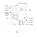
- Fig. 1 contains the overview, and its 3 sub sheets Fig. 2 - Write Port, Fig. 3 - Match Circuit and Fig. 4 - Find Port, in a set-up using two-bit words, rather than the commercial realisation using 128 bit words or 256 bit words.
- the write select lines 0 to 3 select individual Match Circuits 0 to 3, where only one of these is shown on Fig. 1 for the sake of simplicity.
- a write cycle to the Write Port 1 feeds the key field data, equivalent to the hash code, from a physical memory together with the appropriate signals shown in Fig. 2 .
- the logic units U1, U2 and U3 are combined in a way that only one of the bi-state or flip-flop memories is selected as long as the write cycle is active.
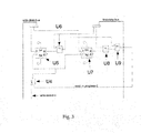
- Fig. 3 shows a wiring diagram and logics of the match circuit which consists of a number of flip-flop memory cells which are interconnected via the logic units U4 to U9 in a way that via U6, U8, and U9, an unequivocal signal is generated at the output of U9 as a comparison bit for the detected presence of a value from the Find-Data bus.
- the memory cells (flip-flops) to be checked are connected to a corresponding input line of the XOR gates U6 and U8, and the second input lines of the said XOR gates U6 and U8 are all connected, the presence of the data looked fro is reflected in the output lines of the said XOR gates. This is why this circuit is referred to as "Match Circuit".
- Fig. 4 shows the wiring and logics of the find circuit.
- the "Read-in-Progress" signals are converted via U10 and U11 to an address if the Find Circuit of Fig. 3 returns a positive response. Should the Find Circuit of Fig. 3 not return a positive response, or if a positive response leads to the same address being calculated via U10 and U11, error handling is activated, and the error bit is fed to U12 resulting in a not/enabled state in CS of U13. In the case of a positive response, the hash code representing the address is provided at the output lines of U13. In this set-up, the Read-in-Progress lines are acting as an arbiter controlling memory access.
- a chemical product was made by a three-step process, where in the first step, the reaction was made by mixing three reactants A1, A2 and A3 at a temperature AT, and reacting for a specified time span AS.
- the masses of the reactants were mA1, mA2 and mA3.
- the recipe was recorded in a first entry into the RFID tag by calculating a hash code from the CAS numbers of the three reactants (Chemical Abstracts Service numbers), their masses, and the reaction temperature(s) and time(s), and stored in the RFID tag fixed to the container or the reaction product B1, using the value of the hash code as key field.
- the product of the first step referred to as B1 was then reacted in the second step with a further chemical B2 at a temperature BT for a time span BS.
- the masses of the reactants were mB1 and mB2.
- the recipe was recorded in a second entry by calculating a hash code from the CAS numbers of the three reactants (Chemical Abstracts Service numbers), their masses, and the reaction temperature(s) and time(s), and stored in the RFID tag fixed to the container or the reaction product, using the value of the hash code as key field. Yield and purity of the resulting reaction product referred to as C1 were determined and also recorded, together with the recipe of the second step, in an RFID tag affixed to the container for the reaction product C1.
- the reaction product C1 of the second step was there transferred to the reaction of the third step, using the auxiliary materials C2, C3, and C4.
- masses of the reactants, their CAS number for identification, and the reaction conditions (temperatures, time spans) were recorded, used to calculate hash code which was then written to an RFID tag affixed to the product of the third reaction step which was then prepared for shipment to the customer.
- the hash code of the prior step as an additional component to calculate the hash code for the reaction product of any stage, it is possible to unequivocally control and document all steps performed which was the basis for the quality control system in this example. All analytical data measured on starting products, intermediates, and final products were also used in calculating the hash codes, as well as date and time of each manufacturing step.
- Example 2 As similar system as described in Example 2 was used to print the hash codes for each step on the RFID tags. Entry into the quality control data base of the manufacturer could also be made off-line once per day as the size of the hash code allowed creation of unique key field values in each case.
- An object O was collected in a place A, where a receipt was issued to the sender, the object was then transported to a hub B, combined in hub B with other objects to the same destination D in a box, transported to a second hub C where the contents of the box were taken out and the object O was then transported to its destination D, and handed over to the recipient R against a receipt.
- the object was identified with an RFID tag which contained information about the sender, the recipient, and the carriers.
- an RFID tag was written with a hand-held electronic device, which had a means of recording the signature of the sender, and affixed to the object O.
- a label for the RFID tag was printed by the hand-held device that contained a hash code calculated from the name and address of the sender, the date and time of collection, and the location of collection which was generated within the hand-held device by a GPS sensor element, a timer system, and the pressure-sensitive signature filed in the hand-held device.
- the first part of the label was printed with a heat-sensitive paper and printing head where the heat-sensitive paper contained randomly dispersed fluorescent pigments.
- the printed zone on the label was then scanned with a blue light-emitting diode, and the position of the fluorescent pigment particles was recorded by the scanning head incorporated into the handheld device, and converted to a series of x and y coordinates which was used together with the first hash code to calculate a second hash code which was then printed as the second part of the label.
- the hash codes are also stored in the RFID tag.
- the previous labels were scanned, and the contents are compared to the content of the RFID tag, so that the identity of the object can be verified.
- the label at location B was generated using the hash code read from the label printed in location A, and complemented by date, time and location recorded by the hand-held device used to scan the label. This procedure was used in all the other locations as well, leading to printed labels for locations a, B, C, and D which allow a full reconstruction of the locations and the times of arrival or departure in these locations.
- Non-encoded information was stored for times, locations, and names of sender and recipient to allow tracing of the object. This information was stored in the RFID in a database format, with the value of the hash codes as key field.
- the second part o the label is unique, and it is particularly not possible to copy because a copy would generate a different second hash code, and therefore, a different second part of the label.
- the authenticity can be controlled at any location by reading the first and the second hash code, and calculating the econf hash code from the first hash code and the position of the fluorescent pigment particles in the first part of the label. Only the original label will lead to the same result.
Abstract
The invention relates to a process to control multi-step processes wherein in one step i of the process, a product Di is made from one or more components Cij by collecting from all components Cij by reading from a mark or a label information which identifies Cij, calculating a hash code Hij from the information from component Cij, calculating a hash code Ji from all hash codes Hij of all components and providing the product Di with a mark comprising the hash code Ji, to an apparatus to provide the marks, and to the use of this process in control and documentation of product or service quality, logistics, or manufacturing.
Description
- The invention relates to a process to control multi-step processes, to an apparatus and a database for use in this process, and to an application of this process in quality control and tracking of manufacturing and logistic processes.
- Tracking of multi-step processes such as manufacturing and/or logistic processes including information on each manufacturing or transport or other service step is presently done by written or printed documents which leave room for exchange or change with only insufficient means to detect and avoid such tampering. It is therefore desired to provide a process that generates a documentation for any product or service which involves more than one step or stage between the supplier and the recipient of such products or services.
- It has been found that marking of an object which is preferably a product itself, or a container which contains the said product, or of a document associated with a service, or constituting the service, with a mark that comprises an identification part which is unique every time it is produced, and optionally, a readable part which can be a printed text or a printed bar or dot code, can be used to unequivocally identify each object. The uniqueness of the identification part of the mark can be ascertained by the introduction of a random element in combination with a method to fix a random distribution to make it permanent.
- In the case of printing, this combination of a random event and a method to permanently fix a random configuration is, according to the invention, made by a toner or an inkjet ink comprising a minor amount of particles that can be identified by any property differing from the properties of the major amount of particles. A "minor" amount in this context refers to a mass fraction of from 0.001 % to less than 50 %, practically between 0.01 % and 1 %. The property which differs for the particles representing the minor amount from the corresponding property of the particles representing the major amount can be a difference in colour, in luminescence, or in magnetic or radioactive properties, e. g. a minor amount of red pigment particles in a black toner, or a minor amount of luminescent pigment particles in an inkjet ink, or magnetic or radioactive particles in a toner or printing ink.
- It is possible to mark the product itself, such as a ready-assembled motor vehicle, or a computer on its housing, a document such as an identification card or a passport, a money bill, or freight documents accompanying a shipment.
- Application of the mark constitutes a step in the multi-step process, preferably also the final step.
- An object of this invention is therefore a process to control multi-step processes wherein in one step i of the process, a product Di is made from one or more components Cij, comprising for each of the process steps i
- collecting from all components Cij used to make the product Di of a process step i, by reading from a mark or a label attached to any component which may be a starting product or a material, used in that process step, information which identifies the said component Cij, where i is an integer number which may assume values from 1 to m, m being equal to the number of steps in the multi-step process, and where j is an integer number which may assume values from 1 to n, where n is equal to the number of components used in a process step i,
- calculating for each j from 1 to n, a hash code Hij from the said information read from component Cij,
- calculating a hash code Ji from all n hash codes Hij of all n components used in process step i, and optionally, additionally from data read from a timer which provides a system time of the equipment used in process step i, and/or from a device providing information about the geographical location where process step i is conducted, and
- providing the product Di of step i with a mark or a label comprising a visual representation of the hash code Ji,
- providing a major amount of particles Pa and a minor amount of at least one kind of particles Pzk, wherein the particles Pa and the particles Pzk differ in at least one physical property
- mixing the said particles Pa and the said minor amount of at least one kind of particles Pzk to provide a mixture M1 of particles,
- applying the mixture M1 to a substrate which is either a product Di made in process step i, or a container containing the product Di, or a label attached to the product Di, and
- fixing the distribution of the said mixture M of particles on the said substrate to provide a fixed mixture Mfi on the said substrate,
- The number k of particles Pzk which are different from the particles Pa is at least one, and preferably, sufficient to detect these particles in a mixture with particles Pa when applied as a mark or a label, or otherwise, on a surface. The value of k may, of course, be different in each step.
- "Multi-step", as used herein, may be one step, or more than one step.
- The product can be an object, or a service, or a document, where the document itself can be the product, or the document can be a description of the product or service.
- A further object of the invention is a multi-step service which is conducted in at least one step wherein any step of the multi-step service can be described or otherwise represented by a document, wherein
- a hash code Ji is calculated from information used to create a document Di, or from the document Di created in, or constituting, the step i,
- optionally, calculating a further hash code J'i from Ji and data read from a timer which provides a system time of the equipment used in process step i, and/or from a device providing information about the geographical location where process step i is conducted or finalised,
- providing the document Di of step i with a mark or a label comprising a visual representation of the hash code Ji or J'i,
- providing a major amount of particles Pa and a minor amount of at least one kind of particles Pzk, wherein the particles Pa and the particles Pzk differ in at least one physical property
- mixing the said particles Pa and the said minor amount of at least one kind of particles Pzk to provide a mixture M1 of particles,
- applying the mixture M1 to a substrate which is either a document Di created in process step i, or a container containing the document Di, or a label attached to the product Di, and
- fixing the distribution of the said mixture M of particles on the said substrate to provide a fixed mixture Mfi on the said substrate,
- The mixtures M1 may be the same, or may be different for each step, and need a sufficient number of particles Pzk, as mentioned supra, to enable the detection of the distribution of the particles Pzk in the fixed mixture, such as in the developed toner image of a printed paper, or in the dried print made with an inkjet printer, or in the partially heated picture generated by a thermal paper printer.
- A further object of this invention is a means of conversion of the information about the detected distribution of particles Pzi in the said fixed mixture Mfi to a hash code HMfi which is used to mark the product Di or document Di which may also describing or constituting the service Di, or the container containing the said document or product or object of service Di, or the label attached to Di, which means of conversion is used in creating the hash code Hi of step i.
- A further object of the invention is a process wherein a mark embodied by a random-generated and fixed distribution of a minor amount of particles is read from the product or products or document or documents of the previous stage, and used together with information relating to the current step i to generate a hash code Hi which is used together with the hash code HMfi to calculate a hash code H"i used for marking the product or document of the instant step i.
- A further object of the invention is a method of storing information about each step of the multistage process in a database where the hash code HMfi or the hash code H"i is used as the key field in the said database, with field entries describing the kind and amount of components Cij used in the present step i, such as raw materials, auxiliary materials, labour, and quality data collected for the components Cij, to make the product Di of the present step, or content and format of the documents on which the document of the present step Di is based.
- The mark is preferably affixed to a product or a document embodying a service in a way that it cannot be detached therefrom, or can only be detached in a mutilated form. A preferred mark comprises two parts that may be spatially separated, where one mark M2 comprises information about the other mark M1, particularly preferred, information about the distribution of particles Pzi in the said fixed mixture Mfi of step i present in the mark M1 which has been converted to a hash code HMfi which hash code is then used to generate and apply the mark M2. Both marks are then read by a detector which responds to the fixed distribution of particles Pzi in both marks M1 and M2, and the hash code generated from this combined information is used in the database as the key field to record all pertinent data for this step i.
- One preferred method of marking a product or a document embodying or relating to, a service, of a selected step i is by use of an RFID tag that contains a hash code Hi which is also printed on the first label of this RFID tag with a toner or an inkjet ink or on a thermal paper containing particles Pa and particles Pzi. The first label or mark M1 is then read by an appropriate reading device, and a hash code HMfi is calculated from the read data, merged or concatenated with the first hash code Hi to form a hash code Ji which is then printed as second label or mark M2 on the RFID tag. This constitutes a self-verifying RFID tag, as any duplication of the first label or the content of the RFID itself will mandatorily lead to a different second label M2. As this RFID tag also comprises information about the previous step by virtue of containing information about the components Cij, from the hash code Hi which is generated from the hash codes of all elements of the previous stage, this verifies the history of each product or document of this stage. This history can be, in the case of a product, a list of kinds and amounts of all materials used to make the product of this step, including manufacturing data such as date and location, if a GPS signal is added to the manufacturing data. In the case of a document being forwarded over several stages with different locations, such as collecting from the sender, a collecting centre, a distribution centre or hub, various airports, a delivery centre, and finally, of the recipient, information about time and location for each of these stages can be recorded by building in each case, a new hash code from the hash code of the prior stage and the distribution of particles in the label of the present stage.
- A document representing a service can preferably be the papers accompanying goods to be delivered. A document embodying or constituting a service is preferably a draft for a contract between two or more parties, or a cheque or a bill of exchange.
- The hash codes for each step can be recorded in a database, where the hash codes themselves constitute the key field of the record in the database, and further specific information like time and location, or starting material data and date and location of a manufacturing stage which is preferably also recorded in this record. It is not needed to request a key field number, as by the use of a hash code of appropriate length, it is ensured that each hash code, or key field, is unique which is mandatory in such database. Therefore, the transitions between steps where a verification is made, does not need a fast internet connection. Update of the database can therefore be made offline.
- The uniqueness of the hash code, and thereby, the key field in the database, is ensured by using the algorithm as described in
DE 10 2007 045 692 . This method of generating the hash code makes sure that all prior stages, i. e. the stages before the stage under consideration, with their characteristic data are comprised in the hash code calculated in a stepwise fashion from these. Exchange of at last one prior step, or of any element used in such prior step, yields a different hash code and therefore easily be detected. - According to a preferred embodiment of the invention, calculation of the hash codes is made by simple boolean logic, which has the advantage of being fast and using only little calculating power.
- This calculation of hash codes and storage thereof is made in a control system referred to as database indexing circuit which comprises
- a writing unit W which has a plurality of data write ports WD and a memory address select port WM, which writing unit writes to a storage medium,
- a random read unit R which has a plurality of data read ports RD, which reading unit reads information in a random or ordered sequence from a storage medium,
- a set of access registers Ai, each of which having write control ports AiWC which feed data to the data write port WD, read control ports AiRC which receive data from the read port RD, the read and write control ports being connected by a set of buses to a logic unit which links the data received from the read port RD and/or the data to be written to the write port WD with the address which is calculated in the logic unit from the data read and/or the data to be written, based on a hash code calculated from the said data in a hash calculation unit, preferably a hardware-based calculation unit, and stores the data on the calculated address and/or reads the data from the calculated address.
- A mobile device for generation and storage of hash codes having the structure of a distributed database is explained here:
- In a mobile write and read device, the extended database structure is based on the potential of RFID tags operated at ultra-high frequency (UHF RFID tags) to allow bulk reading. The bulk writing option is not broadly used as single write operation is far more frequently encountered. The term "bulk rw" when used here only addresses the option to select an individual device in a lot in order to trigger predefined actions in this device. Other than so-called hard-wired circuits, or logical circuits, addressing RFIDs is possible from undefined locations and directions, and not limited to conducting strips on a board. The database concept used here needs multiple addressing, and needs to set entire bus systems in one of three states in order to couple a further bus to the same chip. The "on air" addressing system used in RFIDs avoids this effort which is particularly advantageous when flexibility is more important than speed. Anti-tap security can be provided by simple shielding.
- A mobile device does not have to be geared for high speed because the total speed in relation to the amount of data collected results from the high number of individual mobile devices. Therefore, the large number of mobile devices and their addressing via radio frequency allows the handling of large data volumes by the parallel use of these mobile devices. A system for their use comprises devices to read and write RFID tags in a large number which are collected in a container. The present-day size of RFID tags which for instance may be spherical shaped and have a diameter of about 2 mm, allows to read and write many tags, about one thousand, with a single read-write unit (RWU) in the same, preferably shielded, container as they can be addressed individually. The unit to compute a hash code which is then written may be a separate one connected to the RWU, or may preferably be integrated into the RWU. and has a pistol handle or similar form container wherein the lot of RFID tags is stored. The RWU unit reads the identification codes of all RFID tags in the container in a so-called bulk read, and generates an internal table of these. All products or documents to be marked will then receive an RFID tag containing the assigned calculated hash code, and at the same time a label is printed having the same information, i. e. the RFID tag identification code, and the hash code assigned. In the preferred way, the label has two parts, wherein the second part of the label is generated from reading the first part of the label and the fixed positions of the particles Pzk of the first part of the label. In this case, the hash code generated would be a concatenated hash code calculated from the first hash code and the fixed positions of the particles Pzk. The write process for RFID tags and labels will be repeated for all RFID tags present in the same container. The marked products or documents can then be shipped to their respective recipients, or to a hub from where transport and distribution are made. In a similar way, in any hub or at the recipient, the identity of products or documents received can be checked and verified by bulk reading and verifying of all RFID tags and labels for each received lot. This process does not need the access to the central database as verification can simply be made by checking the identity of RFID tag and label, and both parts of the two-part label. In a process consisting of many steps, the presence, and characteristic data of each step such as time and location, can therefore easily be verified. Upload to an external central data base is easily made by bulk writing outside of normal operating hours.
- The control system for indexing a database is explained in the attached figures which show in
- Fig.1
- an overview of the wiring diagram in a simplified set-up using two-bit words rather than the actual realisation which uses 128 bit words or 256 bit words,
- Fig. 2
- a detail of
Fig. 1 which is the Write Port where data are written to the memory, - Fig. 3
- a detail of
Fig. 1 which is the Match Circuit where the signal from the Data Find bus and the Write Data bus are compared, and Access to Memory at the address calculated in the Find Port as detailed inFig. 4 is granted upon match of these, and - Fig. 4
- a detail of
Fig. 1 which is the Find Port which converts the hash read read to an address in the data base. - The control system for indexing a database used to store the data collected in the process according to the invention is set up as explained in
Fig. 1 , which contains the overview, and its 3 sub sheetsFig. 2 - Write Port,Fig. 3 - Match Circuit andFig. 4 - Find Port, in a set-up using two-bit words, rather than the commercial realisation using 128 bit words or 256 bit words. - Initialising is done here by resetting the Write Port of
Fig. 1 with details shown inFig. 2 with the write-reset line at U1.The following designations for elements are used inFig. 2 :U1 is a binary address counter, U2 is a multiplexer that controls the Write- Select lines 0 to 3 depending on the Write-Select signal X, the Write-Clock, and the Write-Enable state, andU3 is an XOR gate setting the Write-Status. - The write
select lines 0 to 3 selectindividual Match Circuits 0 to 3, where only one of these is shown onFig. 1 for the sake of simplicity. - The individual lines and their meanings are:
Write-Data: 2-bit data input to database are 4 possible combinations needing 4 x 2 = 8 bits memory total Write-Status: 2-bit data output indicating status of database Write-Enable: enable line U1 Write-Clock: square pulse clock Write-Up-Down: change writing direction Write-Reset: clears counter Write-Select: acting as enable for U2 - A write cycle to the
Write Port 1 feeds the key field data, equivalent to the hash code, from a physical memory together with the appropriate signals shown inFig. 2 . - The logic units U1, U2 and U3 are combined in a way that only one of the bi-state or flip-flop memories is selected as long as the write cycle is active.
-
Fig. 3 shows a wiring diagram and logics of the match circuit which consists of a number of flip-flop memory cells which are interconnected via the logic units U4 to U9 in a way that via U6, U8, and U9, an unequivocal signal is generated at the output of U9 as a comparison bit for the detected presence of a value from the Find-Data bus. As all output lines of the memory cells (flip-flops) to be checked are connected to a corresponding input line of the XOR gates U6 and U8, and the second input lines of the said XOR gates U6 and U8 are all connected, the presence of the data looked fro is reflected in the output lines of the said XOR gates. This is why this circuit is referred to as "Match Circuit". -
Fig. 4 shows the wiring and logics of the find circuit. The "Read-in-Progress" signals are converted via U10 and U11 to an address if the Find Circuit ofFig. 3 returns a positive response. Should the Find Circuit ofFig. 3 not return a positive response, or if a positive response leads to the same address being calculated via U10 and U11, error handling is activated, and the error bit is fed to U12 resulting in a not/enabled state in CS of U13. In the case of a positive response, the hash code representing the address is provided at the output lines of U13. In this set-up, the Read-in-Progress lines are acting as an arbiter controlling memory access. - The logic parts used are :
- U4 = nor gate
- U5 = data flipflop
- U6 = xor gate
- U7 = data flip flop
- U8 = xor gate
- U9 = nor gate
- Data on write-data-bus and find-data-bus are compared during the Find operation. If there is no positive response (no match), no additional ram is selected (error state). If the response is positive (match), additional ram is selected and additional data can be stored and/or read. This is done always with respect to the contents of the hash database. So the hash is both the data to be stored but also the indirect index how to find it again and how to concatenate additional data to the corresponding hashes.
- The invention is further explained by the examples which follow.
- A chemical product was made by a three-step process, where in the first step, the reaction was made by mixing three reactants A1, A2 and A3 at a temperature AT, and reacting for a specified time span AS. The masses of the reactants were mA1, mA2 and mA3. The recipe was recorded in a first entry into the RFID tag by calculating a hash code from the CAS numbers of the three reactants (Chemical Abstracts Service numbers), their masses, and the reaction temperature(s) and time(s), and stored in the RFID tag fixed to the container or the reaction product B1, using the value of the hash code as key field.
- The product of the first step referred to as B1 was then reacted in the second step with a further chemical B2 at a temperature BT for a time span BS. The masses of the reactants were mB1 and mB2. The recipe was recorded in a second entry by calculating a hash code from the CAS numbers of the three reactants (Chemical Abstracts Service numbers), their masses, and the reaction temperature(s) and time(s), and stored in the RFID tag fixed to the container or the reaction product, using the value of the hash code as key field. Yield and purity of the resulting reaction product referred to as C1 were determined and also recorded, together with the recipe of the second step, in an RFID tag affixed to the container for the reaction product C1.
- The reaction product C1 of the second step was there transferred to the reaction of the third step, using the auxiliary materials C2, C3, and C4. As in the preceding steps, masses of the reactants, their CAS number for identification, and the reaction conditions (temperatures, time spans) were recorded, used to calculate hash code which was then written to an RFID tag affixed to the product of the third reaction step which was then prepared for shipment to the customer.
- By using the hash code of the prior step as an additional component to calculate the hash code for the reaction product of any stage, it is possible to unequivocally control and document all steps performed which was the basis for the quality control system in this example. All analytical data measured on starting products, intermediates, and final products were also used in calculating the hash codes, as well as date and time of each manufacturing step.
- Additionally, as similar system as described in Example 2 was used to print the hash codes for each step on the RFID tags. Entry into the quality control data base of the manufacturer could also be made off-line once per day as the size of the hash code allowed creation of unique key field values in each case.
- An object O was collected in a place A, where a receipt was issued to the sender, the object was then transported to a hub B, combined in hub B with other objects to the same destination D in a box, transported to a second hub C where the contents of the box were taken out and the object O was then transported to its destination D, and handed over to the recipient R against a receipt. The object was identified with an RFID tag which contained information about the sender, the recipient, and the carriers.
- At the collection point A, an RFID tag was written with a hand-held electronic device, which had a means of recording the signature of the sender, and affixed to the object O. A label for the RFID tag was printed by the hand-held device that contained a hash code calculated from the name and address of the sender, the date and time of collection, and the location of collection which was generated within the hand-held device by a GPS sensor element, a timer system, and the pressure-sensitive signature filed in the hand-held device. The first part of the label was printed with a heat-sensitive paper and printing head where the heat-sensitive paper contained randomly dispersed fluorescent pigments. The printed zone on the label was then scanned with a blue light-emitting diode, and the position of the fluorescent pigment particles was recorded by the scanning head incorporated into the handheld device, and converted to a series of x and y coordinates which was used together with the first hash code to calculate a second hash code which was then printed as the second part of the label. The hash codes are also stored in the RFID tag.
- Further labels are printed in each location where the object is unloaded, and packed to a new vehicle for transport. This series of labels is therefore unique.
- At each of the locations A, B, C, and D, the previous labels were scanned, and the contents are compared to the content of the RFID tag, so that the identity of the object can be verified. The label at location B was generated using the hash code read from the label printed in location A, and complemented by date, time and location recorded by the hand-held device used to scan the label. This procedure was used in all the other locations as well, leading to printed labels for locations a, B, C, and D which allow a full reconstruction of the locations and the times of arrival or departure in these locations. Non-encoded information was stored for times, locations, and names of sender and recipient to allow tracing of the object. This information was stored in the RFID in a database format, with the value of the hash codes as key field. As this hash code, using an adequate length of at least 128 bit, had about 3.4 × 10 38 possible different values, there is negligible probability of generating the same value for the key field twice. This generation of key fields made it possible to generate the database entries without being connected, and having to wait for an assigned value for a key filed. This allowed to enter the database records only once very day to the central database of the logistics company.
- As this second hash code is based on the information used for the first hash code and the random code generated by the random position of the fluorescent particles in the first part of the label, the second part o the label is unique, and it is particularly not possible to copy because a copy would generate a different second hash code, and therefore, a different second part of the label. The authenticity can be controlled at any location by reading the first and the second hash code, and calculating the econf hash code from the first hash code and the position of the fluorescent pigment particles in the first part of the label. Only the original label will lead to the same result.
wherein the label or mark is printed or otherwise applied to a surface of the document Di of step i by a process comprising
Claims (15)
- A process to control multi-step processes wherein, in one step i of the process, a product Di is made from one or more components Cij, comprising for each of the process steps i- collecting from all components Cij used to make the product Di of a process step i, by reading from a mark or a label attached to any component which may be a starting product or a material, used in that process step, information which identifies the said component Cij, where i is an integer number which may assume values from 1 to m, m being equal to the number of steps in the multi-step process, and where j is an integer number which may assume values from 1 to n, where n is equal to the number of components used in a process step i,- calculating for each j from 1 to n, a hash code Hij from the said information read from component Cij,- calculating a hash code Ji from all n hash codes Hij of all n components used in process step i, and optionally, additionally from data read from a timer which provides a system time of the equipment used in process step i, and/or from a device providing information about the geographical location where process step i is conducted, and- providing the product Di of step i with a mark or a label comprising a visual representation of the hash code Ji,wherein the label or mark is printed or otherwise applied to a surface of the product Di of step i by a process comprising- providing a major amount of particles Pa and a minor amount of at least one kind of particles Pzk, wherein the particles Pa and the particles Pzk differ in at least one physical property- mixing the said particles Pa and the said minor amount of at least one kind of particles Pzk to provide a mixture M1 of particles,- applying the mixture Ml to a substrate which is either a product Di made in process step i, or a container containing the product Di, or a label attached to the product Di, and- fixing the distribution of the said mixture M of particles on the said substrate to provide a fixed mixture Mfi on the said substrate,where any of i, j, k, l, m, and n are, independently from each other, an integer number of at least 1.
- The process of claim 1 wherein the product is a multi-step service which is conducted in at least one step wherein any step of the multi-step service can be described or otherwise represented by a document, wherein- a hash code Ji is calculated from information used to create a document Di, or from the document Di created in, or constituting, the step i,- optionally, calculating a further hash code J'i from Ji and data read from a timer which provides a system time of the equipment used in process step i, and/or from a device providing information about the geographical location where process step i is conducted or finalised,- providing the document Di of step i with a mark or a label comprising a visual representation of the hash code Ji or J'i,where i is an integer number which may assume values from 1 to m, where m is equal to the number of steps in the multi-step process,
wherein the label or mark is printed or otherwise applied to a surface of the document Di of step i by a process comprising- providing a major amount of particles Pa and a minor amount of at least one kind of particles Pzk, wherein the particles Pa and the particles Pzk differ in at least one physical property- mixing the said particles Pa and the said minor amount of at least one kind of particles Pzk to provide a mixture M1 of particles,- applying the mixture M1 to a substrate which is either a document Di created in process step i, or a container containing the document Di, or a label attached to the product Di, and- fixing the distribution of the said mixture M of particles on the said substrate to provide a fixed mixture Mfi on the said substrate,where any of i, k, and 1 are, independently from each other, an integer number of at least 1. - The process of claim 1 or of claim 2, wherein a mark embodied by a random-generated and fixed distribution of a minor amount of particles is read from the product or products or document or documents or label or labels of the previous stage, and used together with information relating to the current step i to generate a hash code Hi which is used together with the hash code HMfi to calculate a hash code H"i used for marking the product or document of the instant step i.
- The process of claim 3, wherein information about each step of the multistage process is stored in a database where the hash code HMfi or the hash code H"i is used as the key field in the said database, with field entries describing the kind and amount of components Cij used in the present step i, such as raw materials, auxiliary materials, labour, and quality data collected for the components Cij, to make the product Di of the present step, or content and format of the documents on which the document of the present step Di is based.
- The process of any of claims 1 to 4 wherein the mark is affixed to a product or a document in a way that it cannot be detached therefrom, or can only be detached in a mutilated form.
- The process of claim 5 wherein the mark comprises two parts that are spatially separated, where one mark M2 comprises information about the other mark M1.
- The process of claim 6, wherein mark M2 comprises information about the distribution of particles Pzi in the said fixed mixture Mfi of step i present in the mark M1 which is converted to a hash code HMfi which hash code is then used to generate and apply the mark M2.
- The process of claim 7 wherein an RFID tag is used to mark the product or document of step i, characterised in that the RFID tag contains a hash code Hi which is also printed on the first label of this RFID tag with a toner or an inkjet ink or on a thermal paper containing particles Pa and particles Pzi.
- The process of claim 8 wherein the first label or mark M1 is read by a reading device, and a hash code HMfi is calculated from the read data, merged or concatenated with the first hash code Hi to form a hash code Ji which is then printed as second label or mark M2 on the RFID tag.
- The process of claim 8 wherein a plurality of RFID tags are collected in a container of a read-write unit which reads the identification codes of all RFID tags in the container in a bulk read, and generates an internal table of these, and assigns a calculated hash code to each of the RFID tags in the container.
- The process of claim 10 wherein a label is printed in the read-write unit having the RFID tag identification code, and the hash code assigned.
- The process of claim 11 wherein the label has two parts, wherein the second part of the label is generated from reading the first part of the label and the fixed positions of the particles Pzk of the first part of the label.
- The process of claim 12 wherein the hash code generated is a concatenated hash code calculated from the first hash code and the fixed positions of the particles Pzk.
- The use of the process of any of claims 1 to 13 to verify each step in a multi-step process by applying the process in each single process step.
- The use of the process of any of claims 1 to 13 to verify each step in the generation of a multi-step product or a document prepared in multiple stages for the purpose of control and documentation of product or service quality, logistics, or manufacturing.
Priority Applications (7)
| Application Number | Priority Date | Filing Date | Title |
|---|---|---|---|
| EP20110157617 EP2498206A1 (en) | 2011-03-10 | 2011-03-10 | Process and apparatus to control multi-step processes |
| CN201280019611.XA CN103843019B (en) | 2011-03-10 | 2012-03-12 | Device to document processes |
| KR1020137026536A KR102027327B1 (en) | 2011-03-10 | 2012-03-12 | Device to document processes |
| PCT/EP2012/054305 WO2012120153A1 (en) | 2011-03-10 | 2012-03-12 | Device to document processes |
| EP12714238.8A EP2684159A1 (en) | 2011-03-10 | 2012-03-12 | Device to document processes |
| JP2013557139A JP5972293B2 (en) | 2011-03-10 | 2012-03-12 | Device for documenting a process |
| US14/004,184 US9202179B2 (en) | 2011-03-10 | 2012-03-12 | Device to document processes |
Applications Claiming Priority (1)
| Application Number | Priority Date | Filing Date | Title |
|---|---|---|---|
| EP20110157617 EP2498206A1 (en) | 2011-03-10 | 2011-03-10 | Process and apparatus to control multi-step processes |
Publications (1)
| Publication Number | Publication Date |
|---|---|
| EP2498206A1 true EP2498206A1 (en) | 2012-09-12 |
Family
ID=45954607
Family Applications (2)
| Application Number | Title | Priority Date | Filing Date |
|---|---|---|---|
| EP20110157617 Withdrawn EP2498206A1 (en) | 2011-03-10 | 2011-03-10 | Process and apparatus to control multi-step processes |
| EP12714238.8A Withdrawn EP2684159A1 (en) | 2011-03-10 | 2012-03-12 | Device to document processes |
Family Applications After (1)
| Application Number | Title | Priority Date | Filing Date |
|---|---|---|---|
| EP12714238.8A Withdrawn EP2684159A1 (en) | 2011-03-10 | 2012-03-12 | Device to document processes |
Country Status (6)
| Country | Link |
|---|---|
| US (1) | US9202179B2 (en) |
| EP (2) | EP2498206A1 (en) |
| JP (1) | JP5972293B2 (en) |
| KR (1) | KR102027327B1 (en) |
| CN (1) | CN103843019B (en) |
| WO (1) | WO2012120153A1 (en) |
Families Citing this family (2)
| Publication number | Priority date | Publication date | Assignee | Title |
|---|---|---|---|---|
| US10291796B2 (en) * | 2017-08-22 | 2019-05-14 | Docsolid Llc | Using labels in a document processing system |
| KR20210116967A (en) | 2020-03-18 | 2021-09-28 | 김상수 | Reaping hook sickle molding method |
Citations (6)
| Publication number | Priority date | Publication date | Assignee | Title |
|---|---|---|---|---|
| US20050289083A1 (en) * | 2004-05-24 | 2005-12-29 | Ngai Francis T | System and method for authenticating and validating products |
| US20060174129A1 (en) * | 2005-01-31 | 2006-08-03 | Cyril Brignone | Authentication method and system for tagged items |
| EP1701293A1 (en) * | 2005-03-08 | 2006-09-13 | Adalbert Gubo | Process for the integrity check of lots of individual package units |
| DE102007045692A1 (en) | 2007-09-24 | 2009-04-02 | Adalbert Gubo | Documented event records establishing method for use in quality control of production, involves signing records of documented events selected from other events by electronic signature, which is included in calculation of hash values |
| EP2075738A1 (en) * | 2007-12-27 | 2009-07-01 | Gemalto SA | A method for printing a scanner readable code on a secure object |
| WO2010012059A1 (en) * | 2008-07-28 | 2010-02-04 | Villela Carlos Andre Xavier | Varying position print, method for document authentication and method for counterfeit monitoring |
Family Cites Families (10)
| Publication number | Priority date | Publication date | Assignee | Title |
|---|---|---|---|---|
| KR101041515B1 (en) * | 1999-05-19 | 2011-06-16 | 디지맥 코포레이션 | Methods and systems for controlling computers or linking to Internet resources from physical and electronic objects |
| JP2004342096A (en) * | 2003-04-24 | 2004-12-02 | Sii P & S Inc | Commodity history management device, label issuing device, commodity history management method, label issuing method, commodity history management program, label issuing program and identification information issuing device |
| JP2005242530A (en) * | 2004-02-25 | 2005-09-08 | Hitachi Ltd | History recording system, history recording method, history recording program and terminal for receipt transferer |
| US7687271B2 (en) * | 2004-04-22 | 2010-03-30 | Kodak Graphic Communications Canada Company | Covert authentication method and apparatus |
| US7204421B2 (en) * | 2004-10-27 | 2007-04-17 | Symbol Technologies, Inc. | Method of identifying and authenticating products using an identification pattern and a bar code reader |
| JP4314204B2 (en) * | 2005-03-11 | 2009-08-12 | 株式会社東芝 | Document management method, system and program |
| ATE540515T1 (en) * | 2006-04-13 | 2012-01-15 | Art Of Defence Gmbh | METHOD FOR PROVIDING WEB APPLICATION SECURITY |
| JP2008134726A (en) * | 2006-11-27 | 2008-06-12 | Toshiba Corp | Traceability information recording device, method and program |
| CN102077205B (en) * | 2008-06-27 | 2015-12-16 | 皇家飞利浦电子股份有限公司 | For equipment, the system and method for the authenticity of item inspecting, integrality and/or physical state |
| FR2933216B1 (en) * | 2008-06-27 | 2012-12-21 | Nicolas Reffe | METHOD AND SYSTEM FOR VALIDATING A SUCCESSION OF EVENTS VECUTED BY A DEVICE |
-
2011
- 2011-03-10 EP EP20110157617 patent/EP2498206A1/en not_active Withdrawn
-
2012
- 2012-03-12 EP EP12714238.8A patent/EP2684159A1/en not_active Withdrawn
- 2012-03-12 WO PCT/EP2012/054305 patent/WO2012120153A1/en active Application Filing
- 2012-03-12 KR KR1020137026536A patent/KR102027327B1/en active IP Right Grant
- 2012-03-12 CN CN201280019611.XA patent/CN103843019B/en not_active Expired - Fee Related
- 2012-03-12 JP JP2013557139A patent/JP5972293B2/en not_active Expired - Fee Related
- 2012-03-12 US US14/004,184 patent/US9202179B2/en not_active Expired - Fee Related
Patent Citations (6)
| Publication number | Priority date | Publication date | Assignee | Title |
|---|---|---|---|---|
| US20050289083A1 (en) * | 2004-05-24 | 2005-12-29 | Ngai Francis T | System and method for authenticating and validating products |
| US20060174129A1 (en) * | 2005-01-31 | 2006-08-03 | Cyril Brignone | Authentication method and system for tagged items |
| EP1701293A1 (en) * | 2005-03-08 | 2006-09-13 | Adalbert Gubo | Process for the integrity check of lots of individual package units |
| DE102007045692A1 (en) | 2007-09-24 | 2009-04-02 | Adalbert Gubo | Documented event records establishing method for use in quality control of production, involves signing records of documented events selected from other events by electronic signature, which is included in calculation of hash values |
| EP2075738A1 (en) * | 2007-12-27 | 2009-07-01 | Gemalto SA | A method for printing a scanner readable code on a secure object |
| WO2010012059A1 (en) * | 2008-07-28 | 2010-02-04 | Villela Carlos Andre Xavier | Varying position print, method for document authentication and method for counterfeit monitoring |
Also Published As
| Publication number | Publication date |
|---|---|
| US20140224869A1 (en) | 2014-08-14 |
| JP5972293B2 (en) | 2016-08-17 |
| KR20140071957A (en) | 2014-06-12 |
| WO2012120153A1 (en) | 2012-09-13 |
| CN103843019A (en) | 2014-06-04 |
| EP2684159A1 (en) | 2014-01-15 |
| KR102027327B1 (en) | 2019-10-01 |
| US9202179B2 (en) | 2015-12-01 |
| JP2014509153A (en) | 2014-04-10 |
| CN103843019B (en) | 2017-04-26 |
Similar Documents
| Publication | Publication Date | Title |
|---|---|---|
| CN1303562C (en) | Radio-frequency identification mark and related deterministic device and method, and management system and method | |
| US7479880B2 (en) | Process for the integrity check of lots of individual package units | |
| US8152063B1 (en) | Case labeling for field-packed produce | |
| US20070156281A1 (en) | Tracking system and label for use in conjunction therewith | |
| WO2013170009A1 (en) | Verification of physical encryption taggants uning digital representatives and authentications thereof | |
| BRPI0800754A2 (en) | PRODUCTION CONTROL SYSTEM INTEGRATED BY IMAGE PROCESSING AND AUTOMATED CODING | |
| CN101410312A (en) | Article control system and article control method | |
| CN103593749A (en) | Logistics management system based on RFID | |
| KR20210023994A (en) | Double substance-digital anti-counterfeiting protection of goods | |
| US9852317B2 (en) | Printable, writeable article for tracking counterfeit and diverted products | |
| US9202179B2 (en) | Device to document processes | |
| JP3050221B1 (en) | Inspection / sorting system | |
| ES2291304T3 (en) | A PROCEDURE FOR PRINTING SECURITY DOCUMENTS USING LEAVES WITH IDENTIFIERS. | |
| JP2008247574A (en) | Collation system and collation method during forwarding | |
| JP2004091088A (en) | Delivery management system and delivery managing method | |
| KR20190119464A (en) | Method and apparatus for Logistics by using reusable RFID tag | |
| JP4401204B2 (en) | Delivery inspection system | |
| JP2009286005A (en) | Printer for rewritable printing medium with rfid tag, and method for displaying caution about rewritable printing medium with rfid in this printer | |
| US8214294B2 (en) | Method and system for detection of counterfeit goods using modified standard marking protocols | |
| US9646310B2 (en) | Printable, writeable article for tracking counterfeit and diverted products | |
| CN108345916A (en) | Multifunctional mobile towards retail business manages system and method | |
| JP2017034663A (en) | Printable, writable article for tracking counterfeit and diverted products | |
| Weijing et al. | Design of a material traceability system for multi-star batch production | |
| RU51258U1 (en) | AUTOMATED LEGALITY CONTROL SYSTEM FOR OBJECTS | |
| US20160210587A1 (en) | Method for documenting the delivery process for objects, in particular packages or letters |
Legal Events
| Date | Code | Title | Description |
|---|---|---|---|
| PUAI | Public reference made under article 153(3) epc to a published international application that has entered the european phase |
Free format text: ORIGINAL CODE: 0009012 |
|
| AK | Designated contracting states |
Kind code of ref document: A1 Designated state(s): AL AT BE BG CH CY CZ DE DK EE ES FI FR GB GR HR HU IE IS IT LI LT LU LV MC MK MT NL NO PL PT RO RS SE SI SK SM TR |
|
| AX | Request for extension of the european patent |
Extension state: BA ME |
|
| STAA | Information on the status of an ep patent application or granted ep patent |
Free format text: STATUS: THE APPLICATION IS DEEMED TO BE WITHDRAWN |
|
| 18D | Application deemed to be withdrawn |
Effective date: 20130313 |