EP2498066A2 - Rotation Angle Detection Apparatus - Google Patents
Rotation Angle Detection Apparatus Download PDFInfo
- Publication number
- EP2498066A2 EP2498066A2 EP12158124A EP12158124A EP2498066A2 EP 2498066 A2 EP2498066 A2 EP 2498066A2 EP 12158124 A EP12158124 A EP 12158124A EP 12158124 A EP12158124 A EP 12158124A EP 2498066 A2 EP2498066 A2 EP 2498066A2
- Authority
- EP
- European Patent Office
- Prior art keywords
- equation
- signal
- rotation angle
- magnetic sensor
- correction signal
- Prior art date
- Legal status (The legal status is an assumption and is not a legal conclusion. Google has not performed a legal analysis and makes no representation as to the accuracy of the status listed.)
- Granted
Links
Images
Classifications
-
- G—PHYSICS
- G01—MEASURING; TESTING
- G01D—MEASURING NOT SPECIALLY ADAPTED FOR A SPECIFIC VARIABLE; ARRANGEMENTS FOR MEASURING TWO OR MORE VARIABLES NOT COVERED IN A SINGLE OTHER SUBCLASS; TARIFF METERING APPARATUS; MEASURING OR TESTING NOT OTHERWISE PROVIDED FOR
- G01D5/00—Mechanical means for transferring the output of a sensing member; Means for converting the output of a sensing member to another variable where the form or nature of the sensing member does not constrain the means for converting; Transducers not specially adapted for a specific variable
- G01D5/12—Mechanical means for transferring the output of a sensing member; Means for converting the output of a sensing member to another variable where the form or nature of the sensing member does not constrain the means for converting; Transducers not specially adapted for a specific variable using electric or magnetic means
- G01D5/244—Mechanical means for transferring the output of a sensing member; Means for converting the output of a sensing member to another variable where the form or nature of the sensing member does not constrain the means for converting; Transducers not specially adapted for a specific variable using electric or magnetic means influencing characteristics of pulses or pulse trains; generating pulses or pulse trains
- G01D5/24471—Error correction
-
- G—PHYSICS
- G01—MEASURING; TESTING
- G01D—MEASURING NOT SPECIALLY ADAPTED FOR A SPECIFIC VARIABLE; ARRANGEMENTS FOR MEASURING TWO OR MORE VARIABLES NOT COVERED IN A SINGLE OTHER SUBCLASS; TARIFF METERING APPARATUS; MEASURING OR TESTING NOT OTHERWISE PROVIDED FOR
- G01D5/00—Mechanical means for transferring the output of a sensing member; Means for converting the output of a sensing member to another variable where the form or nature of the sensing member does not constrain the means for converting; Transducers not specially adapted for a specific variable
- G01D5/12—Mechanical means for transferring the output of a sensing member; Means for converting the output of a sensing member to another variable where the form or nature of the sensing member does not constrain the means for converting; Transducers not specially adapted for a specific variable using electric or magnetic means
- G01D5/244—Mechanical means for transferring the output of a sensing member; Means for converting the output of a sensing member to another variable where the form or nature of the sensing member does not constrain the means for converting; Transducers not specially adapted for a specific variable using electric or magnetic means influencing characteristics of pulses or pulse trains; generating pulses or pulse trains
- G01D5/245—Mechanical means for transferring the output of a sensing member; Means for converting the output of a sensing member to another variable where the form or nature of the sensing member does not constrain the means for converting; Transducers not specially adapted for a specific variable using electric or magnetic means influencing characteristics of pulses or pulse trains; generating pulses or pulse trains using a variable number of pulses in a train
- G01D5/2451—Incremental encoders
Definitions
- the invention relates to a rotation angle detection apparatus that detects a rotation angle of a rotor.
- a brushless motor that is used in, for example, an electric power steering system is controlled by supplying currents to stator coils in accordance with the rotation angle of a rotor.
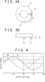
- rotation angle detection apparatuses such as the one illustrated in FIGs. 3A and 3B , are known.
- the illustrated rotation angle detection apparatus includes a detection rotor 1 that rotates as a rotor of a brushless motor rotates, and two magnetic sensors 11 and 12 that are arranged apart from each other at an angular interval of 90° about the rotation axis of the detection rotor 1.
- the detection rotor 1 includes two magnets 2 each of which has two magnetic poles.
- the magnetic sensors 11 and 12 output sinusoidal signals of which the phases are different from each other by 90°.
- the rotation angle of the detection rotor 1 is detected based on the two sinusoidal signals (for example, refer to Japanese Patent Application Publication No. 06-109750 ( JP 06-109750 A ) and Japanese Patent Application Publication No. 2008-283762 ( JP 2008-283762 A )).
- the arrow in FIG. 3A indicates the normal rotation direction of the detection rotor 1. As the detection rotor 1 rotates in the normal rotation direction, the rotation angle of the detection rotor 1 increases. On the other hand, as the detection rotor 1 rotates in the reverse rotation direction, the rotation angle of the detection rotor 1 decreases.
- A1 and A2 each represent an amplitude.
- the first output signal V1 which is one of the two output signals
- V1 A • sin ⁇
- V2 A • cos ⁇
- FIG. 4 is a graph illustrating the waveforms of the first and second output signals V1 and V2.
- the rotation angle ⁇ of the rotor 1 is determined using the first and second output signals V1 and V2, according to, for example, Equation 1 shown below.
- the rotation angle ⁇ calculated based on the first and second output signals V1 and V2 may have a calculation error.
- An aspect of the invention relates to a rotation angle detection apparatus, including: a magnet that rotates as a rotor rotates, and that has multiple magnetic poles arranged in a circumferential direction of the magnet; a first magnetic sensor that outputs, as the magnet rotates, a sinusoidal signal on which a third harmonic component is superimposed; a second magnetic sensor that outputs, as the magnet rotates, a sinusoidal signal on which a third harmonic component is superimposed and of which a phase is different from a phase of the sinusoidal signal output from the first magnetic sensor; a third harmonic component removing unit that corrects the sinusoidal signals output from the first magnetic sensor and the second magnetic sensor so as to remove the third harmonic components from the sinusoidal signals; and a rotation angle calculating unit that calculates a rotation angle of the rotor based on the sinusoidal signals corrected by the third harmonic component removing unit.
- the third harmonic component removing unit includes: a unit that calculates a post-correction signal V1a of the sinusoidal signal output from the first magnetic sensor according to an equation a; and a unit that calculates a post-correction signal V2a of the sinusoidal signal output from the second magnetic sensor according to an equation b.
- K is a third harmonic component gain that is larger than zero but smaller than 1 (0 ⁇ K ⁇ 1)
- V1 is the sinusoidal signal output from the first magnetic sensor
- V1a is the post-correction signal that is obtained by correcting the output signal V1 using the third harmonic component removing unit
- V1b is a pre-correction signal that is the output signal V1 before correction
- V2 is the sinusoidal signal output from the second magnetic sensor
- V2a is the post-correction signal that is obtained by correcting the output signal V2 using the third harmonic component removing unit
- V2b is a pre-correction signal that is the output signal V2 before correction.
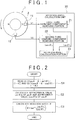
- FIG. 1 is a view schematically showing the configuration of a rotation angle detection apparatus according to the example embodiment of the invention.
- the rotation angle detection apparatus may be used, for example, to detect the rotation angle of a rotor of a brushless motor of an electric power steering system.
- the rotation angle detection apparatus includes, for example, a detection rotor 1 (will hereinafter be simply referred to as "rotor 1") that rotates as the brushless motor rotates.
- the rotor 1 has a cylindrical magnet 2 having at least one magnetic pole pair.
- the magnet 2 has one magnetic pole pair. That is, the magnet 2 has two magnetic poles, that is, an N pole and an S pole, which are equiangularly arranged.
- magnetic sensors 11 and 12 which are opposed to an annular end face of the magnet 2, which is a part of one of end faces of the rotor 1, orthogonal to the rotation axis of the rotor 1.
- the magnetic sensors 11 and 12 are arranged so as to be apart from each other at an angular interval of 90° (electric angle) about the rotation axis of the rotor 1.
- These magnetic sensors 11 and 12 may each be, for example, a magnetic sensor that includes an element of which the electric characteristics change under the influence of a magnetic field, such as a Hall element and a magnetoresistance element (MR element). It is to be noted that one of the two magnetic sensors will be referred to as "the first magnetic sensor 11" where necessary, while the other of the two magnetic sensors will be referred to as "the second magnetic sensor 12" where necessary.
- the arrow in FIG. 1 indicates the normal rotation direction of the rotor 1. As the rotor 1 rotates in the normal rotation direction, the rotation angle of the rotor 1 increases. On the other hand, as the rotor 1 rotates in the reverse rotation direction, the rotation angle of the rotor 1 decreases.
- the rotation angle (electric angle) of the rotor 1 is ⁇
- the first output signal V1 A1 • sin ⁇
- the second output signal V2 A2 • cos ⁇
- the first output signal V1 of the first magnetic sensor 11 is expressed as A • sin ⁇
- the second output signal V2 of the second magnetic sensor 12 is expressed as A • cos ⁇ .
- the first output signal V1 is expressed as sin ⁇
- the second output signal V2 is expressed as cos ⁇ .
- Equation 2 the first output signal V1 expressed as Equation 2 below is output from the first magnetic sensor 11 and the second output signal V2 expressed as Equation 3 below is output from the second magnetic sensor 12.
- K in Equations 3 and 3 below represents a gain K (0 ⁇ K ⁇ 1) of third harmonic components.
- the first output signal V1 and the second output signal V2 are input into a rotation angle calculation unit 20.
- the rotation angle calculation unit 20 calculates the rotation angle ⁇ of the rotor 1 based on the first output signal V1 and the second output signal V2.
- the rotation angle calculation unit 20 is constituted of, for example, a microcomputer including a CPU (Central Processing Unit) and memories, such as a ROM (Read Only Memory) and a RAM (Random Access Memory).
- the rotation angle calculation unit 20 serves as multiple function processing portions (elements) when the CPU executes given programs stored in the ROM.
- the multiple function processing portions include a first third harmonic component removing portion 21 (an example of "third harmonic component removing unit"), a second third harmonic component removing portion 22 (another example of “third harmonic component removing unit”), and a rotation angle calculation portion 23 (an example of "rotation angle calculating unit").
- the first third harmonic component removing portion 21 corrects the first output signal V1 so as to remove the third harmonic components from the first output signal V1. More specifically, at this time, the first third harmonic component removing portion 21 calculates an approximate value (sin ⁇ ) n of a signal sin ⁇ that is the first output signal V1 of the first magnetic sensor 11 from which the third harmonic components have been removed.
- the second third harmonic component removing portion 22 corrects the second output signal V2 so as to remove the third harmonic components from the second output signal V2. More specifically, the second third harmonic component removing portion 22 calculates an approximate value (cos ⁇ ) n of a signal cos ⁇ that is the second output signal V2 of the second magnetic sensor 12 from which the third harmonic components have been removed.
- the processings executed by the first third harmonic component removing portion 21 and the second third harmonic component removing portion 22 will be described.
- Equation 5 V ⁇ 1 ⁇ 1 1 + 4 ⁇ K 1 - K ⁇ 1 - sin 2 ⁇ ⁇
- Equation 6 is a set of equations that are used to calculate, based on Equation 5, the approximate value (sin ⁇ ) n of the signal sin ⁇ that is the first output signal V1 of the first magnetic sensor 11 from which the third harmonic components have been removed.
- sin ⁇ 1 V ⁇ 1 ⁇ 1 1 + 4 ⁇ K 1 - K ⁇ 1 - V ⁇ 1 2
- sin ⁇ 2 V ⁇ 1 ⁇ 1 1 + 4 ⁇ K 1 - K ⁇ 1 - sin ⁇ 1 2
- sin ⁇ n V ⁇ 1 ⁇ 1 1 + 4 ⁇ K 1 - K ⁇ 1 - sin ⁇ n - 1 2
- an approximate value (sin ⁇ ) 1 of sin ⁇ in the first calculation cycle is calculated using the first output signal V1 of the first magnetic sensor 11 as sin ⁇ in the term (1 - sin 2 ⁇ ) in the right side of Equation 5.
- the approximate value (sin ⁇ ) 2 of sin ⁇ in the second calculation cycle is calculated using the approximate value (sin ⁇ ) of sin ⁇ calculated in the first calculation cycle as sin ⁇ in the term (1 - sin 2 ⁇ ) in the right side of Equation 5.
- the approximate value (sin ⁇ ) n of sin ⁇ calculated in each of the second calculation cycle and the following calculation cycles is calculated using an approximate value (sin ⁇ ) n-1 of sin ⁇ calculated in the immediately preceding calculation cycle as sin ⁇ in the term (1 - sin 2 ⁇ ) in the right side of Equation 5. It is to be noted that the larger the calculation cycle number n, the higher the accuracy of the approximate value obtained.
- the first third harmonic component removing portion 21 calculates a signal value (sin ⁇ ) n of sin ⁇ in the nth calculation cycle by executing the calculation described above for n times. It is to be noted the calculation cycle number n may be set to any value. That is, n may one or may be two or more. In this example embodiment, the calculation cycle number n is set to 2 or 3. Next, the processing executed by the second third harmonic component removing portion 22 will be described.
- Equation 7 is obtained by transforming Equation 3 shown above.
- Equation 8 is used to calculate, based on Equation 7, the approximate value (cos ⁇ ) n of the signal cos ⁇ that is the second output signal V2 of the second magnetic sensor 12 from which the third harmonic components have been removed.
- cos ⁇ 1 V ⁇ 2 ⁇ 1 1 + 4 ⁇ K 1 - K ⁇ 1 - V ⁇ 2 2
- cos ⁇ 2 V ⁇ 2 ⁇ 1 1 + 4 ⁇ K 1 - K ⁇ 1 - cos ⁇ 1 2
- cos ⁇ n V ⁇ 2 ⁇ 1 1 + 4 ⁇ K 1 - K ⁇ 1 - cos ⁇ n - 1 2
- an approximate value (cos ⁇ ) 1 of the signal cos ⁇ in the first calculation cycle is calculated using the second output signal V2 of the second magnetic sensor 12 as cos ⁇ in the term (1 - cos 2 ⁇ ) in the right side of Equation 7.
- an approximate value (cos ⁇ ) 2 of cos ⁇ in the second calculation cycle is calculated using the approximate value (cos ⁇ ) 1 calculated in the first calculation cycle as cos ⁇ in the term (1 - cos 2 ⁇ ) in the right side of Equation 7.
- the approximate value (cos ⁇ ) n of cos ⁇ calculated in each of the second calculation cycle and the following calculation cycles is calculated using an approximate value (cos ⁇ ) n-1 of cos ⁇ calculated in the immediately preceding calculation cycle as cos ⁇ in the term (1 - cos 2 ⁇ ) in the right side of Equation 7. It is to be noted that the larger the calculation cycle number n, the higher the accuracy of the approximate value obtained.
- the second third harmonic component removing portion 22 calculates a signal value (cos ⁇ ) n in the nth calculation cycle by executing the calculation described above for n times.
- the calculation cycle number n may be set to any value. That is, n may one, or may be two or more. In this example embodiment, the calculation cycle number n is set to 2 or 3.
- FIG. 2 is a flowchart illustrating the procedure of the rotation angle calculation routine that is executed by the rotation angle calculation unit 20. The rotation angle calculation routine illustrated in FIG. 2 is repeatedly executed at given calculation intervals.
- the rotation angle calculation unit 20 firsts reads the first output signal V1 of the first magnetic sensor 11 and the second output signal V2 of the second magnetic sensor 12 (step S1). After this, the rotation angle calculation unit 20 removes the third harmonic components from the output signals V1 and V2 read in step S1 (step S2). More specifically, at this time, the first third harmonic component removing portion 21 calculates the approximate value (sin ⁇ ) n of the signal sin ⁇ that is the first output signal V1 from which the third harmonic components have been removed. Further, the second third harmonic component removing portion 22 calculates the approximate value (cos ⁇ ) n of the signal cos ⁇ that is the second output signal V2 from which the third harmonic components have been removed.
- the rotation angle calculation portion 23 of the rotation angle calculation unit 20 calculates the rotation angle ⁇ of the rotor 1 using the approximate value (sin ⁇ ) n of sin ⁇ , which has been calculated by the first third harmonic component removing portion 21, and the approximate value (cos ⁇ ) n of cos ⁇ , which has been calculated by the second third harmonic component removing portion 22, according to Equation 4 (step S3). Then, the present cycle of the rotation angle calculation routine is finished.
- the signal value that is the first output signal V1 of the first magnetic sensor 11 from which the third harmonic components have been removed and the signal value that is the second output signal V2 of the second magnetic sensor 12 from which the third harmonic components have been removed are approximately calculated, even if third harmonic components are superimposed on the first output signal V1 of the first magnetic sensor 11 and the second output signal V2 of the second magnetic sensor 12, the rotation angle of the rotor 1 is accurately calculated. In this way, even if the gap between the first magnetic sensor 11 and the magnet 2 and the gap between the second magnetic sensor 12 and the magnet 2 are small, the rotation angle of the rotor 1 is calculated with high accuracy. As a result, the gap between the first magnetic sensor 11 and the magnet 2 and the gap between the second magnetic sensor 12 and the magnet 2 are made smaller, which contributes to size reduction of a rotation angle detection apparatus.
- the method for calculating the rotation angle ⁇ of the rotor 1 based on the approximate value (sin ⁇ ) n of sin ⁇ and the approximate value (cos ⁇ ) n of cos ⁇ is not limited to the above-described method using Equation 4. Further, if 4K / (1 - K) in Equations 6 and 8 is regarded as a correction gain G, the correction gain G may either be constant or be calculated based on the approximate value (sin ⁇ ) n-1 of sin ⁇ calculated in the immediately preceding calculation cycle and the approximate value (cos ⁇ ) n-1 of cos ⁇ calculated in the immediately preceding calculation cycle.
- the correction gain G n that is used when the approximate values (sin ⁇ ) n and (cos ⁇ ) n in the nth calculation cycle are calculated may be calculated based on the approximate value (sin ⁇ ) n-1 of sin ⁇ calculated in the (n-1)th calculation cycle and the approximate value (cos ⁇ ) n-1 of cos ⁇ calculated in the (n-1)th calculation cycle.
- the correction gain G n may be calculated based on the value at the point which corresponds to the rotation angle ⁇ of 45° and at which the sinusoidal curve of the approximate value (sin ⁇ ) n-1 of sin ⁇ calculated in the (n - 1)th calculation cycle and the sinusoidal curve of the approximate value (cos ⁇ ) n-1 of cos ⁇ calculated in the (n - 1)th calculation cycle intersect with each other.
- G n G n - 1 + ⁇ ⁇ 1 - sin ⁇ n - 1 2 / cos ⁇ n - 1 2
- G n-1 the correction gain that is used in the (n-1)th approximate value calculation cycle
- ⁇ is a predetermined constant.
- the first magnetic sensor 11 and the second magnetic sensor 12 are arranged so as to be apart from each other at an angular interval (electric angle) of 90° about the rotation axis of the rotor 1.
- the angular interval between the first magnetic sensor 11 and the second magnetic sensor 12 is not limited 90°. That is, the angular interval may be set to any desired angle (electric angle), for example, 120°.
- description will be made on the processings that are executed by the first third harmonic component removing portion 21 and the second third harmonic component removing portion 22 when the first magnetic sensor 11 and the second magnetic sensor 12 are arranged so as to be apart from each other at a desired angular interval.
- the first third harmonic component removing portion 21 calculates the corrected signal V1a according to Equation 10 shown below. Further, if the output signal of the second magnetic sensor 12 is the second output signal V2, the signal obtained by correcting the second output signal V2 using the second third harmonic component removing portion 22 is V2a, and the second output signal V2 before correction is V2b, the second third harmonic component removing portion 22 calculates the corrected signal V2a according to Equation 11 shown below.
- V ⁇ 1 ⁇ a V ⁇ 1 ⁇ 1 1 + 4 ⁇ K 1 - K ⁇ 1 - V ⁇ 1 ⁇ b 2
- V ⁇ 2 ⁇ a V ⁇ 2 ⁇ 1 1 + 4 ⁇ K 1 - K ⁇ 1 - V ⁇ 2 ⁇ b 2
- the applications of the invention are not limit to such an apparatus. That is, for example, the invention may be applied also to an apparatus that detects the rotation angle of a rotor other than a rotor of a brushless motor. Further, while the magnet of the rotor 1 has a pair of magnetic poles in the foregoing example embodiment, the rotor 1 may have two or more pairs of magnetic poles.
Landscapes
- Physics & Mathematics (AREA)
- General Physics & Mathematics (AREA)
- Transmission And Conversion Of Sensor Element Output (AREA)
- Measurement Of Length, Angles, Or The Like Using Electric Or Magnetic Means (AREA)
Abstract
Description
- The invention relates to a rotation angle detection apparatus that detects a rotation angle of a rotor.
- A brushless motor that is used in, for example, an electric power steering system is controlled by supplying currents to stator coils in accordance with the rotation angle of a rotor. For example, rotation angle detection apparatuses, such as the one illustrated in
FIGs. 3A and 3B , are known. The illustrated rotation angle detection apparatus includes adetection rotor 1 that rotates as a rotor of a brushless motor rotates, and twomagnetic sensors detection rotor 1. Thedetection rotor 1 includes twomagnets 2 each of which has two magnetic poles. Themagnetic sensors detection rotor 1 is detected based on the two sinusoidal signals (for example, refer to Japanese Patent Application Publication No.06-109750 JP 06-109750 A 2008-283762 JP 2008-283762 A - The arrow in
FIG. 3A indicates the normal rotation direction of thedetection rotor 1. As thedetection rotor 1 rotates in the normal rotation direction, the rotation angle of thedetection rotor 1 increases. On the other hand, as thedetection rotor 1 rotates in the reverse rotation direction, the rotation angle of thedetection rotor 1 decreases. If the rotation angle (electric angle) of thedetection rotor 1 is θ, an output signal V1 of the first magnetic sensor 11 (will hereinafter be referred to as "the first output signal V1"), which is one of the two magnetic sensors, is expressed as V1 = A1 • sinθ, and an output signal V2 of the second magnetic sensor 12(will hereinafter be referred to as "the second output signal V2"), which is the other of the two magnetic sensors, is expressed as V2 = A2 • sin (0 + 90°) = A2 • cosθ. In these equations, A1 and A2 each represent an amplitude. - If the amplitudes A1 and A2 are both regarded as a prescribed value A, or if the first and second output signals V1 and V2 are normalized such that the amplitudes A1 and A2 both become the prescribed value A, the first output signal V1, which is one of the two output signals, is expressed as V1 = A • sinθ, and the second output signal V2, which is the other of the two output signals, is expressed as V2 = A • cosθ. Further, if A is 1, the first output signal V1 is expressed as V1 = sinθ and the second output signal V2 is expressed as V2 = cosθ. Thus, for simpler descriptions, the first output signal V1 of the first
magnetic sensor 11 and the second output signal V2 of the secondmagnetic sensor 12 will be expressed as V1 = sinθ and V2 = cosθ, respectively.FIG. 4 is a graph illustrating the waveforms of the first and second output signals V1 and V2. - The rotation angle θ of the
rotor 1 is determined using the first and second output signals V1 and V2, according to, for example,Equation 1 shown below.
- In the conventional rotation angle detection apparatus as described above, if the gap between the first
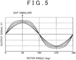
magnetic sensor 11 and therotor 1 and the gap between the secondmagnetic sensor 12 and therotor 1 are small, third harmonic components are superimposed on the first output signal V1 of the firstmagnetic sensor 11 and the second output signal V2 of the secondmagnetic sensor 12, causing distortion of the waveforms of the first and second output signals V1 and V2. For example, as shown inFIG. 5 , the smaller the gap D (refer toFIG. 3B ) between the firstmagnetic sensor 11 and thedetection rotor 1, the larger the distortion of the first output signal V1 of the firstmagnetic sensor 11. In a case where the first output signal V1 of the firstmagnetic sensor 11 and the second output signal V2 of the secondmagnetic sensor 12 are distorted as in this example case, the rotation angle θ calculated based on the first and second output signals V1 and V2 may have a calculation error. - It is an object of the invention to provide a rotation angle detection apparatus that is capable of accurately detecting the rotation angle of a rotor even if third harmonic components are superimposed on output signals of magnetic sensors.
- An aspect of the invention relates to a rotation angle detection apparatus, including: a magnet that rotates as a rotor rotates, and that has multiple magnetic poles arranged in a circumferential direction of the magnet; a first magnetic sensor that outputs, as the magnet rotates, a sinusoidal signal on which a third harmonic component is superimposed; a second magnetic sensor that outputs, as the magnet rotates, a sinusoidal signal on which a third harmonic component is superimposed and of which a phase is different from a phase of the sinusoidal signal output from the first magnetic sensor; a third harmonic component removing unit that corrects the sinusoidal signals output from the first magnetic sensor and the second magnetic sensor so as to remove the third harmonic components from the sinusoidal signals; and a rotation angle calculating unit that calculates a rotation angle of the rotor based on the sinusoidal signals corrected by the third harmonic component removing unit. The third harmonic component removing unit includes: a unit that calculates a post-correction signal V1a of the sinusoidal signal output from the first magnetic sensor according to an equation a; and a unit that calculates a post-correction signal V2a of the sinusoidal signal output from the second magnetic sensor according to an equation b.


In the equation a and the equation b, K is a third harmonic component gain that is larger than zero but smaller than 1 (0 < K < 1), V1 is the sinusoidal signal output from the first magnetic sensor, V1a is the post-correction signal that is obtained by correcting the output signal V1 using the third harmonic component removing unit, V1b is a pre-correction signal that is the output signal V1 before correction, V2 is the sinusoidal signal output from the second magnetic sensor, V2a is the post-correction signal that is obtained by correcting the output signal V2 using the third harmonic component removing unit, and V2b is a pre-correction signal that is the output signal V2 before correction. - The foregoing and further features and advantages of the invention will become apparent from the following description of example embodiments with reference to the accompanying drawings, wherein like numerals are used to represent like elements and wherein:
-
FIG. 1 is a view schematically showing the configuration of a rotation angle detection apparatus according to an example embodiment of the invention; -
FIG. 2 is a flowchart illustrating the procedure of a rotation angle calculation routine that is executed by a rotation angle calculation unit; -
FIG. 3A and 3B are views for explaining a rotation angle detection method that is executed by a conventional rotation angle detection apparatus, whereFIG. 3A shows the conventional rotation angle detection apparatus as viewed in the axial direction of a detection rotor of the rotation angle detection apparatus, andFIG. 3B is a plan view of the conventional rotation angle detection apparatus; -
FIG. 4 is a graph showing waveforms of output signals of magnetic sensors; and -
FIG. 5 is a waveform diagram showing examples of waveforms of an output signal of a first magnetic sensor, on which third harmonic components are superimposed. - In the following, an example embodiment of the invention will be described in detail with reference to the accompanying drawings. In the example embodiment, the invention is applied to a rotation angle detection apparatus that detects the rotation angle of a rotor of a brushless motor.
FIG. 1 is a view schematically showing the configuration of a rotation angle detection apparatus according to the example embodiment of the invention. The rotation angle detection apparatus may be used, for example, to detect the rotation angle of a rotor of a brushless motor of an electric power steering system. The rotation angle detection apparatus includes, for example, a detection rotor 1 (will hereinafter be simply referred to as "rotor 1") that rotates as the brushless motor rotates. Therotor 1 has acylindrical magnet 2 having at least one magnetic pole pair. In this example embodiment, themagnet 2 has one magnetic pole pair. That is, themagnet 2 has two magnetic poles, that is, an N pole and an S pole, which are equiangularly arranged. - There are provided two
magnetic sensors magnet 2, which is a part of one of end faces of therotor 1, orthogonal to the rotation axis of therotor 1. Themagnetic sensors rotor 1. Thesemagnetic sensors magnetic sensor 11" where necessary, while the other of the two magnetic sensors will be referred to as "the secondmagnetic sensor 12" where necessary. - The arrow in
FIG. 1 indicates the normal rotation direction of therotor 1. As therotor 1 rotates in the normal rotation direction, the rotation angle of therotor 1 increases. On the other hand, as therotor 1 rotates in the reverse rotation direction, the rotation angle of therotor 1 decreases. If the rotation angle (electric angle) of therotor 1 is θ, in a state where third harmonic components are superimposed on neither an output signal V1 of the first magnetic sensor 11 (will hereinafter be referred to as "the first output signal V1" where necessary) nor an output signal V2 of the second magnetic sensor 12 (will hereinafter be referred to as "the second output signal V2" where necessary), the first output signal V1 of the firstmagnetic sensor 11 is expressed as V1 = A1 • sinθ, and the second output signal V2 of the secondmagnetic sensor 12 is expressed as V2 = A2 • sin (θ + 90°) = A2 • cosθ. In these equations, A1 and A2 each represent an amplitude. If the amplitudes A1 and A2 are both regarded as a prescribed value A, or if the output signals V1 and V2 are normalized such that the amplitudes A1 and A2 both become the prescribed value A, the first output signal V1 of the firstmagnetic sensor 11 is expressed as A • sinθ, and the second output signal V2 of the secondmagnetic sensor 12 is expressed as A • cosθ. When the prescribed value A is 1 (A = 1), the first output signal V1 is expressed as sinθ and the second output signal V2 is expressed as cosθ. Therefore, in a situation where third harmonic components are superimposed on neither the first output signal V1 nor the second output signal V2, the first output signal V1 that is expressed as V1 = sinθ is output from the firstmagnetic sensor 11 and the second output signal V2 that is expressed as V2 = cosθ is output from the secondmagnetic sensor 12. - In this example embodiment, because the gap between the first
magnetic sensor 11 and themagnet 2 and the gap between the secondmagnetic sensor 12 and themagnet 2 are small, third harmonic components are superimposed on the first output signal V1 of the firstmagnetic sensor 11 and the second output signal V2 of the secondmagnetic sensor 12. Therefore, in this example embodiment, the first output signal V1 expressed asEquation 2 below is output from the firstmagnetic sensor 11 and the second output signal V2 expressed as Equation 3 below is output from the secondmagnetic sensor 12. It is to be noted that K in Equations 3 and 3 below represents a gain K (0 < K < 1) of third harmonic components.

- The first output signal V1 and the second output signal V2 are input into a rotation
angle calculation unit 20. The rotationangle calculation unit 20 calculates the rotation angle θ of therotor 1 based on the first output signal V1 and the second output signal V2. The rotationangle calculation unit 20 is constituted of, for example, a microcomputer including a CPU (Central Processing Unit) and memories, such as a ROM (Read Only Memory) and a RAM (Random Access Memory). The rotationangle calculation unit 20 serves as multiple function processing portions (elements) when the CPU executes given programs stored in the ROM. The multiple function processing portions (elements) include a first third harmonic component removing portion 21 (an example of "third harmonic component removing unit"), a second third harmonic component removing portion 22 (another example of "third harmonic component removing unit"), and a rotation angle calculation portion 23 (an example of "rotation angle calculating unit"). - The first third harmonic
component removing portion 21 corrects the first output signal V1 so as to remove the third harmonic components from the first output signal V1. More specifically, at this time, the first third harmoniccomponent removing portion 21 calculates an approximate value (sinθ)n of a signal sinθ that is the first output signal V1 of the firstmagnetic sensor 11 from which the third harmonic components have been removed. The second third harmoniccomponent removing portion 22 corrects the second output signal V2 so as to remove the third harmonic components from the second output signal V2. More specifically, the second third harmoniccomponent removing portion 22 calculates an approximate value (cosθ)n of a signal cosθ that is the second output signal V2 of the secondmagnetic sensor 12 from which the third harmonic components have been removed. - The rotation
angle calculation portion 23 calculates the rotation angle θ of therotor 1 based on the approximate value (sinθ)n of the signal sinθ, which has been calculated by the first third harmoniccomponent removing portion 21, and the approximate value (cosθ)n of the signal cosθ, which has been calculated by the second third harmoniccomponent removing portion 22. More specifically, the rotationangle calculation portion 23 calculates the rotation angle θ of therotor 1 based on Equation 4 shown below.
In the following, the processings executed by the first third harmoniccomponent removing portion 21 and the second third harmoniccomponent removing portion 22 will be described. - First, the processing executed by the first third harmonic
component removing portion 21 will be described. Equation 5 shown below is obtained by transformingEquation 2.
- Equation 6 is a set of equations that are used to calculate, based on Equation 5, the approximate value (sinθ)n of the signal sinθ that is the first output signal V1 of the first
magnetic sensor 11 from which the third harmonic components have been removed.

- As shown in Equation 6 above, an approximate value (sinθ)1 of sinθ in the first calculation cycle is calculated using the first output signal V1 of the first
magnetic sensor 11 as sinθ in the term (1 - sin2θ) in the right side of Equation 5. Further, the approximate value (sinθ)2 of sinθ in the second calculation cycle is calculated using the approximate value (sinθ) of sinθ calculated in the first calculation cycle as sinθ in the term (1 - sin2θ) in the right side of Equation 5. That is, if the number of calculation cycles is n (n is an integer that is equal to or larger than 1), the approximate value (sinθ)n of sinθ calculated in each of the second calculation cycle and the following calculation cycles is calculated using an approximate value (sinθ)n-1 of sinθ calculated in the immediately preceding calculation cycle as sinθ in the term (1 - sin2θ) in the right side of Equation 5. It is to be noted that the larger the calculation cycle number n, the higher the accuracy of the approximate value obtained. - The first third harmonic
component removing portion 21 calculates a signal value (sinθ)n of sinθ in the nth calculation cycle by executing the calculation described above for n times. It is to be noted the calculation cycle number n may be set to any value. That is, n may one or may be two or more. In this example embodiment, the calculation cycle number n is set to 2 or 3. Next, the processing executed by the second third harmoniccomponent removing portion 22 will be described. - Equation 7 is obtained by transforming Equation 3 shown above.

- Equation 8 is used to calculate, based on Equation 7, the approximate value (cosθ)n of the signal cosθ that is the second output signal V2 of the second
magnetic sensor 12 from which the third harmonic components have been removed.

- As is known from Equation 8 shown above, an approximate value (cosθ)1 of the signal cosθ in the first calculation cycle is calculated using the second output signal V2 of the second
magnetic sensor 12 as cosθ in the term (1 - cos2θ) in the right side of Equation 7. Further, an approximate value (cosθ)2 of cosθ in the second calculation cycle is calculated using the approximate value (cosθ)1 calculated in the first calculation cycle as cosθ in the term (1 - cos2θ) in the right side of Equation 7. That is, if the number of calculation cycles is n (n is an integer that is equal to or larger than 1), the approximate value (cosθ)n of cosθ calculated in each of the second calculation cycle and the following calculation cycles is calculated using an approximate value (cosθ)n-1 of cosθ calculated in the immediately preceding calculation cycle as cosθ in the term (1 - cos2θ) in the right side of Equation 7. It is to be noted that the larger the calculation cycle number n, the higher the accuracy of the approximate value obtained. - The second third harmonic
component removing portion 22 calculates a signal value (cosθ)n in the nth calculation cycle by executing the calculation described above for n times. It is to be noted that the calculation cycle number n may be set to any value. That is, n may one, or may be two or more. In this example embodiment, the calculation cycle number n is set to 2 or 3.FIG. 2 is a flowchart illustrating the procedure of the rotation angle calculation routine that is executed by the rotationangle calculation unit 20. The rotation angle calculation routine illustrated inFIG. 2 is repeatedly executed at given calculation intervals. - Referring to the flowchart in
FIG. 2 , the rotationangle calculation unit 20 firsts reads the first output signal V1 of the firstmagnetic sensor 11 and the second output signal V2 of the second magnetic sensor 12 (step S1). After this, the rotationangle calculation unit 20 removes the third harmonic components from the output signals V1 and V2 read in step S1 (step S2). More specifically, at this time, the first third harmoniccomponent removing portion 21 calculates the approximate value (sinθ)n of the signal sinθ that is the first output signal V1 from which the third harmonic components have been removed. Further, the second third harmoniccomponent removing portion 22 calculates the approximate value (cosθ)n of the signal cosθ that is the second output signal V2 from which the third harmonic components have been removed. - The rotation
angle calculation portion 23 of the rotationangle calculation unit 20 calculates the rotation angle θ of therotor 1 using the approximate value (sinθ)n of sinθ, which has been calculated by the first third harmoniccomponent removing portion 21, and the approximate value (cosθ)n of cosθ, which has been calculated by the second third harmoniccomponent removing portion 22, according to Equation 4 (step S3). Then, the present cycle of the rotation angle calculation routine is finished. According to this example embodiment, because the signal value that is the first output signal V1 of the firstmagnetic sensor 11 from which the third harmonic components have been removed and the signal value that is the second output signal V2 of the secondmagnetic sensor 12 from which the third harmonic components have been removed are approximately calculated, even if third harmonic components are superimposed on the first output signal V1 of the firstmagnetic sensor 11 and the second output signal V2 of the secondmagnetic sensor 12, the rotation angle of therotor 1 is accurately calculated. In this way, even if the gap between the firstmagnetic sensor 11 and themagnet 2 and the gap between the secondmagnetic sensor 12 and themagnet 2 are small, the rotation angle of therotor 1 is calculated with high accuracy. As a result, the gap between the firstmagnetic sensor 11 and themagnet 2 and the gap between the secondmagnetic sensor 12 and themagnet 2 are made smaller, which contributes to size reduction of a rotation angle detection apparatus. - While the example embodiment of the invention has been described above, the invention may be embodied in various other embodiments. For example, the method for calculating the rotation angle θ of the
rotor 1 based on the approximate value (sinθ)n of sinθ and the approximate value (cosθ)n of cosθ is not limited to the above-described method using Equation 4. Further, if 4K / (1 - K) in Equations 6 and 8 is regarded as a correction gain G, the correction gain G may either be constant or be calculated based on the approximate value (sinθ)n-1 of sinθ calculated in the immediately preceding calculation cycle and the approximate value (cosθ)n-1 of cosθ calculated in the immediately preceding calculation cycle. In this case, for example, the correction gain Gn that is used when the approximate values (sinθ)n and (cosθ)n in the nth calculation cycle are calculated may be calculated based on the approximate value (sinθ)n-1 of sinθ calculated in the (n-1)th calculation cycle and the approximate value (cosθ)n-1 of cosθ calculated in the (n-1)th calculation cycle. At this time, more specifically, the correction gain Gn may be calculated based on the value at the point which corresponds to the rotation angle θ of 45° and at which the sinusoidal curve of the approximate value (sinθ)n-1 of sinθ calculated in the (n - 1)th calculation cycle and the sinusoidal curve of the approximate value (cosθ)n-1 of cosθ calculated in the (n - 1)th calculation cycle intersect with each other. - Further, when the approximate value (sinθ) of sinθ calculated in the (n - 1)th cycle and the approximate value (cosθ)n-1 of cosθ calculated in the (n - 1)th cycle contain third harmonic components, (sinθ)n-1 2 + (cosθ)n-1 2 is not 1 ((sinθ)n-1 2 + (cosθ)n-1 2 ≠ 1). Therefore, the correction gain (4K / (1 - K)) that is used when the approximate values (sinθ)n and (cosθ)n in the nth calculation cycle are calculated may be calculated according to Equation 9 shown below.

In Equation 9 above, Gn is the correction gain that is used in the nth approximate value calculation cycle, and Gn-1 is the correction gain that is used in the (n-1)th approximate value calculation cycle, and α is a predetermined constant.
As described above, by adjusting the correction gain G, it is possible to cope with a change in time in the gap between the firstmagnetic sensor 11 and themagnet 2, a change in time in the gap between the secondmagnetic sensor 12 and themagnet 2, and individual differences among products (rotation angle detection apparatuses). As a result, it is possible to calculate the rotation angle of therotor 1 with high accuracy. - In the example embodiment described above, the first
magnetic sensor 11 and the secondmagnetic sensor 12 are arranged so as to be apart from each other at an angular interval (electric angle) of 90° about the rotation axis of therotor 1. However, the angular interval between the firstmagnetic sensor 11 and the secondmagnetic sensor 12 is not limited 90°. That is, the angular interval may be set to any desired angle (electric angle), for example, 120°. Hereinafter, description will be made on the processings that are executed by the first third harmoniccomponent removing portion 21 and the second third harmoniccomponent removing portion 22 when the firstmagnetic sensor 11 and the secondmagnetic sensor 12 are arranged so as to be apart from each other at a desired angular interval. If K (0 < K < 1) is a gain of third harmonic components, the output signal of the firstmagnetic sensor 11 is the first output signal V1, the signal obtained by correcting the first output signal V1 using the first third harmoniccomponent removing portion 21 is V1a, and the first output signal V1 before correction is V1b, the first third harmoniccomponent removing portion 21 calculates the corrected signal V1a according to Equation 10 shown below. Further, if the output signal of the secondmagnetic sensor 12 is the second output signal V2, the signal obtained by correcting the second output signal V2 using the second third harmoniccomponent removing portion 22 is V2a, and the second output signal V2 before correction is V2b, the second third harmoniccomponent removing portion 22 calculates the corrected signal V2a according toEquation 11 shown below.

- While the example embodiment where the invention is applied to an apparatus that detects the rotation angle of a rotor of a brushless motor has been described, the applications of the invention are not limit to such an apparatus. That is, for example, the invention may be applied also to an apparatus that detects the rotation angle of a rotor other than a rotor of a brushless motor. Further, while the magnet of the
rotor 1 has a pair of magnetic poles in the foregoing example embodiment, therotor 1 may have two or more pairs of magnetic poles. - The invention has been described with reference to the example embodiment for illustrative purposes only. It should be understood that the description is not intended to be exhaustive or to limit form of the invention and that the invention may be adapted for use in other systems and applications. The scope of the invention embraces various modifications and equivalent arrangements that may be conceived by one skilled in the art.
Claims (4)
- A rotation angle detection apparatus, comprising:a magnet that rotates as a rotor rotates, and that has multiple magnetic poles arranged in a circumferential direction of the magnet;a first magnetic sensor that outputs, as the magnet rotates, a sinusoidal signal on which a third harmonic component is superimposed;a second magnetic sensor that outputs, as the magnet rotates, a sinusoidal signal on which a third harmonic component is superimposed and of which a phase is different from a phase of the sinusoidal signal output from the first magnetic sensor;a third harmonic component removing unit that corrects the sinusoidal signals output from the first magnetic sensor and the second magnetic sensor so as to remove the third harmonic components from the sinusoidal signals; anda rotation angle calculating unit that calculates a rotation angle of the rotor based on the sinusoidal signals corrected by the third harmonic component removing unit, whereinthe third harmonic component removing unit comprises:a unit that calculates a post-correction signal V1a of the sinusoidal signal output from the first magnetic sensor according to an equation a; anda unit that calculates a post-correction signal V2a of the sinusoidal signal output from the second magnetic sensor according to an equation b,


wherein K is a third harmonic component gain that is larger than zero but smaller than 1 (0 < K < 1), V1 is the sinusoidal signal output from the first magnetic sensor, V1a is the post-correction signal that is obtained by correcting the output signal V1 using the third harmonic component removing unit, V1b is a pre-correction signal that is the output signal V1 before correction, V2 is the sinusoidal signal output from the second magnetic sensor, V2a is the post-correction signal that is obtained by correcting the output signal V2 using the third harmonic component removing unit, and V2b is a pre-correction signal that is the output signal V2 before correction. - The rotation angle detection apparatus according to claim 1, wherein
the third harmonic component removing unit comprises:a unit that calculates the post-correction signal V1a in a final calculation cycle, using the output signal V1 as the pre-correction signal V1b in the equation a; anda unit that calculates the post-correction signal V2a in the final calculation cycle, using the output signal V2 as the pre-correction signal V2b in the equation b. - The rotation angle detection apparatus according to claim 1, wherein
the third harmonic component removing unit comprises:a unit that calculates the post correction signal V1a in a first calculation cycle, using the output signal V1 as the pre-correction signal V1b in the equation a;a unit that calculates the post-correction signal V1a in a final calculation cycle by executing, at least one time, a process in which the post-correction signals V1a in a second calculation cycle and calculation cycles following the second calculation cycle are each calculated using the post-correction signal V1a calculated in an immediately preceding calculation cycle as the pre-correction signal V1b in the equation a;a unit that calculates the post-correction signal V2a in the first calculation cycle, using the output signal V2 as the pre-correction signal V2b in the equation b; anda unit that calculates the post-correction signal V2a in the final calculation cycle by executing, at least one time, a process in which the post-correction signals V2a in the second calculation cycle and the calculation cycles following the second calculation cycle are each calculated using the post-correction signal V2a calculated in an immediately preceding calculation cycle as the pre-correction signal V2b in the equation b. - The rotation angle detection apparatus according to any of claims 1 to 3, wherein
if the rotation angle of the rotor is θ, the output signal V1 is expressed by an equation c where θ represents the rotation angle of the rotor, and the output signal V2 is expressed by an equation d where θ represents the rotation angle of the rotor, the equation a is an equation e obtained from the equation c, the equation b is an equation f obtained from the equation d, the pre-correction signal V1b corresponds to sisθ in a term (1 - sin2θ) in a right side of the equation e, the post-correction signal V1a corresponds to sinθ in a left side of the equation e, the pre-correction signal V2b corresponds to cosθ in a term (1 - cos2θ) in a right side of the equation f, and the post-correction signal V2a corresponds to cosθ in a left side of the equation f


Applications Claiming Priority (1)
| Application Number | Priority Date | Filing Date | Title |
|---|---|---|---|
| JP2011051637A JP5660381B2 (en) | 2011-03-09 | 2011-03-09 | Rotation angle detector |
Publications (3)
| Publication Number | Publication Date |
|---|---|
| EP2498066A2 true EP2498066A2 (en) | 2012-09-12 |
| EP2498066A3 EP2498066A3 (en) | 2014-11-05 |
| EP2498066B1 EP2498066B1 (en) | 2016-02-03 |
Family
ID=45841258
Family Applications (1)
| Application Number | Title | Priority Date | Filing Date |
|---|---|---|---|
| EP12158124.3A Not-in-force EP2498066B1 (en) | 2011-03-09 | 2012-03-05 | Rotation angle detection apparatus |
Country Status (4)
| Country | Link |
|---|---|
| US (1) | US8942952B2 (en) |
| EP (1) | EP2498066B1 (en) |
| JP (1) | JP5660381B2 (en) |
| CN (1) | CN102679864B (en) |
Cited By (4)
| Publication number | Priority date | Publication date | Assignee | Title |
|---|---|---|---|---|
| EP3792601A4 (en) * | 2018-05-11 | 2022-02-16 | Sankyo Seisakusho Co. | ANGLE DETECTOR |
| DE102023002859A1 (en) | 2023-07-14 | 2025-01-16 | Mercedes-Benz Group AG | Method for determining a torque of an electrical machine, in particular of a motor vehicle, electrical machine and motor vehicle |
| DE102023002862A1 (en) | 2023-07-14 | 2025-01-16 | Mercedes-Benz Group AG | Method for operating an electrical machine, in particular a motor vehicle, and electrical machine, in particular for a motor vehicle |
| DE102023002856A1 (en) | 2023-07-14 | 2025-01-16 | Mercedes-Benz Group AG | Method for operating an electrical machine, method for operating a motor vehicle and electrical machine |
Families Citing this family (10)
| Publication number | Priority date | Publication date | Assignee | Title |
|---|---|---|---|---|
| JP6075855B2 (en) * | 2013-01-25 | 2017-02-08 | 株式会社エー・アンド・デイ | Rotation analysis apparatus and method |
| JP6210284B2 (en) * | 2013-09-18 | 2017-10-11 | 株式会社ジェイテクト | Rotation angle detector |
| JP6432129B2 (en) * | 2013-11-28 | 2018-12-05 | 株式会社リコー | Angle detection device and angle detection method |
| JP5731022B1 (en) * | 2014-01-07 | 2015-06-10 | ソフトロニクス株式会社 | Absolute position detector |
| US10103607B2 (en) * | 2014-10-20 | 2018-10-16 | Mitsubishi Electric Corporation | Rotation angle detector, rotary electrical machine and elevator hoisting machine |
| DE102015101363B4 (en) * | 2015-01-30 | 2019-05-23 | Infineon Technologies Ag | Detecting a rotational position of a shaft |
| CN104748768B (en) * | 2015-03-12 | 2017-07-25 | 常州大学 | Detection method of rotation angle position detection device |
| US10584953B2 (en) * | 2015-11-26 | 2020-03-10 | Mitsubishi Electric Corporation | Angle detection device and electric power steering device |
| KR101963106B1 (en) * | 2016-11-29 | 2019-04-01 | 주식회사 해치텍 | Apparatus for detecting an angle of rotation |
| US12292280B2 (en) * | 2022-12-20 | 2025-05-06 | Allegro Microsystems, Llc | Angle sensor |
Citations (2)
| Publication number | Priority date | Publication date | Assignee | Title |
|---|---|---|---|---|
| JPH06109750A (en) | 1992-09-29 | 1994-04-22 | Mazda Motor Corp | Rotation sensor |
| JP2008283762A (en) | 2007-05-09 | 2008-11-20 | Aisin Seiki Co Ltd | DC motor ripple detection device, motor rotational position detection device, and ripple detection method |
Family Cites Families (24)
| Publication number | Priority date | Publication date | Assignee | Title |
|---|---|---|---|---|
| JP2839340B2 (en) * | 1990-08-09 | 1998-12-16 | 三菱化学株式会社 | Calibration device for position signal |
| JP2001012967A (en) * | 1999-04-28 | 2001-01-19 | Asahi Optical Co Ltd | Surveying instrument equipped with encoder and magnetic encoder |
| JP3930227B2 (en) * | 2000-06-14 | 2007-06-13 | ペンタックス株式会社 | Surveyor equipped with magnetic encoder and magnetic encoder |
| DE10041089A1 (en) | 2000-08-22 | 2002-03-07 | Bosch Gmbh Robert | Procedure for correcting an angle measurement |
| JP4552353B2 (en) * | 2001-05-11 | 2010-09-29 | ソニー株式会社 | Servo actuator and its position detector |
| US6859762B2 (en) * | 2001-07-03 | 2005-02-22 | Mitutoyo Corporation | Low voltage low power signal processing system and method for high accuracy processing of differential signal inputs from a low power measuring instrument |
| DE10163504B4 (en) * | 2001-12-21 | 2005-07-07 | Siemens Ag | Method for iterative error compensation of sin / cos position measuring systems for offset, amplitude and phase errors |
| JP4713117B2 (en) * | 2004-09-21 | 2011-06-29 | 株式会社ミツトヨ | Encoder output signal correction apparatus and method |
| JP4713123B2 (en) * | 2004-10-13 | 2011-06-29 | 株式会社ミツトヨ | Encoder output signal correction device |
| JP2006226764A (en) * | 2005-02-16 | 2006-08-31 | Shicoh Eng Co Ltd | Position detection device |
| JP4578298B2 (en) * | 2005-03-22 | 2010-11-10 | 株式会社ミツトヨ | Encoder output signal waveform correction device |
| JP2007121216A (en) * | 2005-10-31 | 2007-05-17 | Aisin Seiki Co Ltd | Rotation state detection device |
| US7898245B2 (en) * | 2006-05-12 | 2011-03-01 | Kabushiki Kaisha Yaskawa Denki | Magnetic encoder |
| JP4862485B2 (en) * | 2006-05-17 | 2012-01-25 | 日本精工株式会社 | Resolver digital converter, rotation angle position detection device, and rotation machine control device |
| JP4763509B2 (en) * | 2006-05-23 | 2011-08-31 | アイシン精機株式会社 | Ripple detector |
| TWI393867B (en) * | 2007-04-20 | 2013-04-21 | Mitsubishi Electric Corp | Magnetic rotation angle detector |
| JP2008304249A (en) * | 2007-06-06 | 2008-12-18 | Yaskawa Electric Corp | Encoder signal processing apparatus and signal processing method thereof |
| WO2009099054A1 (en) * | 2008-02-07 | 2009-08-13 | Hitachi Metals, Ltd. | Rotation angle detection device, rotary machine, and rotation angle detection method |
| JP5557021B2 (en) * | 2009-08-26 | 2014-07-23 | 株式会社ジェイテクト | Rotation angle detector |
| JP5333863B2 (en) * | 2009-08-26 | 2013-11-06 | 株式会社ジェイテクト | Rotation angle detector |
| JP5807770B2 (en) * | 2010-12-15 | 2015-11-10 | 株式会社ジェイテクト | Rotation angle detector |
| JP5776925B2 (en) * | 2010-12-17 | 2015-09-09 | 株式会社ジェイテクト | Rotation angle detector |
| JP5720932B2 (en) * | 2011-01-17 | 2015-05-20 | 株式会社ジェイテクト | Rotation angle detector |
| JP5716954B2 (en) * | 2011-01-17 | 2015-05-13 | 株式会社ジェイテクト | Rotation angle detector |
-
2011
- 2011-03-09 JP JP2011051637A patent/JP5660381B2/en not_active Expired - Fee Related
-
2012
- 2012-02-27 CN CN201210047809.0A patent/CN102679864B/en not_active Expired - Fee Related
- 2012-02-29 US US13/408,415 patent/US8942952B2/en not_active Expired - Fee Related
- 2012-03-05 EP EP12158124.3A patent/EP2498066B1/en not_active Not-in-force
Patent Citations (2)
| Publication number | Priority date | Publication date | Assignee | Title |
|---|---|---|---|---|
| JPH06109750A (en) | 1992-09-29 | 1994-04-22 | Mazda Motor Corp | Rotation sensor |
| JP2008283762A (en) | 2007-05-09 | 2008-11-20 | Aisin Seiki Co Ltd | DC motor ripple detection device, motor rotational position detection device, and ripple detection method |
Cited By (5)
| Publication number | Priority date | Publication date | Assignee | Title |
|---|---|---|---|---|
| EP3792601A4 (en) * | 2018-05-11 | 2022-02-16 | Sankyo Seisakusho Co. | ANGLE DETECTOR |
| US11573103B2 (en) | 2018-05-11 | 2023-02-07 | Sankyo Seisakusho Co. | Angle detector |
| DE102023002859A1 (en) | 2023-07-14 | 2025-01-16 | Mercedes-Benz Group AG | Method for determining a torque of an electrical machine, in particular of a motor vehicle, electrical machine and motor vehicle |
| DE102023002862A1 (en) | 2023-07-14 | 2025-01-16 | Mercedes-Benz Group AG | Method for operating an electrical machine, in particular a motor vehicle, and electrical machine, in particular for a motor vehicle |
| DE102023002856A1 (en) | 2023-07-14 | 2025-01-16 | Mercedes-Benz Group AG | Method for operating an electrical machine, method for operating a motor vehicle and electrical machine |
Also Published As
| Publication number | Publication date |
|---|---|
| CN102679864A (en) | 2012-09-19 |
| JP5660381B2 (en) | 2015-01-28 |
| US20120232839A1 (en) | 2012-09-13 |
| CN102679864B (en) | 2016-03-09 |
| EP2498066B1 (en) | 2016-02-03 |
| JP2012189375A (en) | 2012-10-04 |
| EP2498066A3 (en) | 2014-11-05 |
| US8942952B2 (en) | 2015-01-27 |
Similar Documents
| Publication | Publication Date | Title |
|---|---|---|
| EP2498066B1 (en) | Rotation angle detection apparatus | |
| EP2466268B1 (en) | Rotation angle detection device | |
| EP2873951A1 (en) | Rotation angle detecting device | |
| EP2477003B1 (en) | Rotation angle detecting device | |
| US8933692B2 (en) | Rotation angle detection device | |
| EP2498063A2 (en) | Rotation angle detection device | |
| CN102564295B (en) | Rotation angle detection device and electric power steering apparatus using same | |
| EP2559971B1 (en) | Rotation angle detection device | |
| US8957675B2 (en) | Rotation angle detection device | |
| EP2472233A1 (en) | Device for detecting angle of rotation | |
| US11984837B2 (en) | Method for determining an angular position of a rotating component, in particular of an electric motor for a clutch actuation system of a vehicle | |
| EP2498064A2 (en) | Rotation Angle Detection Device and Torque Detection Device | |
| JP5892359B2 (en) | Rotation angle detector | |
| JP2011047735A (en) | Rotational angle detecting device | |
| US10753772B2 (en) | Resolver having decreased permanence error due to harmonic components | |
| US11578993B2 (en) | Determining a relative movement direction | |
| US10101396B2 (en) | Detection of current sensor malfunction | |
| JP6112832B2 (en) | Angle correction device and rotation angle sensor | |
| JP7209877B2 (en) | Angle detector | |
| JP2010249719A (en) | Minute angle detection sensor | |
| JP2018205112A (en) | Rotation angle detection method and device using resolver, and motor | |
| WO2024143256A1 (en) | Angle detecting device | |
| JP2024054797A (en) | Rotation angle detection device, rotation angle detection method, and rotation angle detection program |
Legal Events
| Date | Code | Title | Description |
|---|---|---|---|
| PUAI | Public reference made under article 153(3) epc to a published international application that has entered the european phase |
Free format text: ORIGINAL CODE: 0009012 |
|
| AK | Designated contracting states |
Kind code of ref document: A2 Designated state(s): AL AT BE BG CH CY CZ DE DK EE ES FI FR GB GR HR HU IE IS IT LI LT LU LV MC MK MT NL NO PL PT RO RS SE SI SK SM TR |
|
| AX | Request for extension of the european patent |
Extension state: BA ME |
|
| PUAL | Search report despatched |
Free format text: ORIGINAL CODE: 0009013 |
|
| AK | Designated contracting states |
Kind code of ref document: A3 Designated state(s): AL AT BE BG CH CY CZ DE DK EE ES FI FR GB GR HR HU IE IS IT LI LT LU LV MC MK MT NL NO PL PT RO RS SE SI SK SM TR |
|
| AX | Request for extension of the european patent |
Extension state: BA ME |
|
| RIC1 | Information provided on ipc code assigned before grant |
Ipc: G01D 5/244 20060101AFI20140930BHEP Ipc: G01D 5/245 20060101ALI20140930BHEP |
|
| 17P | Request for examination filed |
Effective date: 20150317 |
|
| RBV | Designated contracting states (corrected) |
Designated state(s): AL AT BE BG CH CY CZ DE DK EE ES FI FR GB GR HR HU IE IS IT LI LT LU LV MC MK MT NL NO PL PT RO RS SE SI SK SM TR |
|
| GRAP | Despatch of communication of intention to grant a patent |
Free format text: ORIGINAL CODE: EPIDOSNIGR1 |
|
| RIC1 | Information provided on ipc code assigned before grant |
Ipc: G01D 5/245 20060101ALI20150708BHEP Ipc: G01D 5/244 20060101AFI20150708BHEP |
|
| INTG | Intention to grant announced |
Effective date: 20150720 |
|
| GRAS | Grant fee paid |
Free format text: ORIGINAL CODE: EPIDOSNIGR3 |
|
| GRAA | (expected) grant |
Free format text: ORIGINAL CODE: 0009210 |
|
| AK | Designated contracting states |
Kind code of ref document: B1 Designated state(s): AL AT BE BG CH CY CZ DE DK EE ES FI FR GB GR HR HU IE IS IT LI LT LU LV MC MK MT NL NO PL PT RO RS SE SI SK SM TR |
|
| REG | Reference to a national code |
Ref country code: GB Ref legal event code: FG4D |
|
| REG | Reference to a national code |
Ref country code: AT Ref legal event code: REF Ref document number: 773905 Country of ref document: AT Kind code of ref document: T Effective date: 20160215 Ref country code: CH Ref legal event code: EP |
|
| REG | Reference to a national code |
Ref country code: IE Ref legal event code: FG4D |
|
| REG | Reference to a national code |
Ref country code: DE Ref legal event code: R096 Ref document number: 602012014279 Country of ref document: DE |
|
| REG | Reference to a national code |
Ref country code: FR Ref legal event code: PLFP Year of fee payment: 5 |
|
| REG | Reference to a national code |
Ref country code: LT Ref legal event code: MG4D Ref country code: NL Ref legal event code: MP Effective date: 20160203 |
|
| REG | Reference to a national code |
Ref country code: AT Ref legal event code: MK05 Ref document number: 773905 Country of ref document: AT Kind code of ref document: T Effective date: 20160203 |
|
| PG25 | Lapsed in a contracting state [announced via postgrant information from national office to epo] |
Ref country code: HR Free format text: LAPSE BECAUSE OF FAILURE TO SUBMIT A TRANSLATION OF THE DESCRIPTION OR TO PAY THE FEE WITHIN THE PRESCRIBED TIME-LIMIT Effective date: 20160203 Ref country code: GR Free format text: LAPSE BECAUSE OF FAILURE TO SUBMIT A TRANSLATION OF THE DESCRIPTION OR TO PAY THE FEE WITHIN THE PRESCRIBED TIME-LIMIT Effective date: 20160504 Ref country code: IT Free format text: LAPSE BECAUSE OF FAILURE TO SUBMIT A TRANSLATION OF THE DESCRIPTION OR TO PAY THE FEE WITHIN THE PRESCRIBED TIME-LIMIT Effective date: 20160203 Ref country code: NO Free format text: LAPSE BECAUSE OF FAILURE TO SUBMIT A TRANSLATION OF THE DESCRIPTION OR TO PAY THE FEE WITHIN THE PRESCRIBED TIME-LIMIT Effective date: 20160503 Ref country code: FI Free format text: LAPSE BECAUSE OF FAILURE TO SUBMIT A TRANSLATION OF THE DESCRIPTION OR TO PAY THE FEE WITHIN THE PRESCRIBED TIME-LIMIT Effective date: 20160203 Ref country code: ES Free format text: LAPSE BECAUSE OF FAILURE TO SUBMIT A TRANSLATION OF THE DESCRIPTION OR TO PAY THE FEE WITHIN THE PRESCRIBED TIME-LIMIT Effective date: 20160203 |
|
| PG25 | Lapsed in a contracting state [announced via postgrant information from national office to epo] |
Ref country code: LV Free format text: LAPSE BECAUSE OF FAILURE TO SUBMIT A TRANSLATION OF THE DESCRIPTION OR TO PAY THE FEE WITHIN THE PRESCRIBED TIME-LIMIT Effective date: 20160203 Ref country code: PT Free format text: LAPSE BECAUSE OF FAILURE TO SUBMIT A TRANSLATION OF THE DESCRIPTION OR TO PAY THE FEE WITHIN THE PRESCRIBED TIME-LIMIT Effective date: 20160603 Ref country code: RS Free format text: LAPSE BECAUSE OF FAILURE TO SUBMIT A TRANSLATION OF THE DESCRIPTION OR TO PAY THE FEE WITHIN THE PRESCRIBED TIME-LIMIT Effective date: 20160203 Ref country code: PL Free format text: LAPSE BECAUSE OF FAILURE TO SUBMIT A TRANSLATION OF THE DESCRIPTION OR TO PAY THE FEE WITHIN THE PRESCRIBED TIME-LIMIT Effective date: 20160203 Ref country code: NL Free format text: LAPSE BECAUSE OF FAILURE TO SUBMIT A TRANSLATION OF THE DESCRIPTION OR TO PAY THE FEE WITHIN THE PRESCRIBED TIME-LIMIT Effective date: 20160203 Ref country code: BE Free format text: LAPSE BECAUSE OF NON-PAYMENT OF DUE FEES Effective date: 20160331 Ref country code: AT Free format text: LAPSE BECAUSE OF FAILURE TO SUBMIT A TRANSLATION OF THE DESCRIPTION OR TO PAY THE FEE WITHIN THE PRESCRIBED TIME-LIMIT Effective date: 20160203 Ref country code: IS Free format text: LAPSE BECAUSE OF FAILURE TO SUBMIT A TRANSLATION OF THE DESCRIPTION OR TO PAY THE FEE WITHIN THE PRESCRIBED TIME-LIMIT Effective date: 20160603 Ref country code: LT Free format text: LAPSE BECAUSE OF FAILURE TO SUBMIT A TRANSLATION OF THE DESCRIPTION OR TO PAY THE FEE WITHIN THE PRESCRIBED TIME-LIMIT Effective date: 20160203 Ref country code: SE Free format text: LAPSE BECAUSE OF FAILURE TO SUBMIT A TRANSLATION OF THE DESCRIPTION OR TO PAY THE FEE WITHIN THE PRESCRIBED TIME-LIMIT Effective date: 20160203 |
|
| PG25 | Lapsed in a contracting state [announced via postgrant information from national office to epo] |
Ref country code: EE Free format text: LAPSE BECAUSE OF FAILURE TO SUBMIT A TRANSLATION OF THE DESCRIPTION OR TO PAY THE FEE WITHIN THE PRESCRIBED TIME-LIMIT Effective date: 20160203 Ref country code: DK Free format text: LAPSE BECAUSE OF FAILURE TO SUBMIT A TRANSLATION OF THE DESCRIPTION OR TO PAY THE FEE WITHIN THE PRESCRIBED TIME-LIMIT Effective date: 20160203 |
|
| REG | Reference to a national code |
Ref country code: CH Ref legal event code: PL |
|
| REG | Reference to a national code |
Ref country code: DE Ref legal event code: R097 Ref document number: 602012014279 Country of ref document: DE |
|
| PG25 | Lapsed in a contracting state [announced via postgrant information from national office to epo] |
Ref country code: CZ Free format text: LAPSE BECAUSE OF FAILURE TO SUBMIT A TRANSLATION OF THE DESCRIPTION OR TO PAY THE FEE WITHIN THE PRESCRIBED TIME-LIMIT Effective date: 20160203 Ref country code: SM Free format text: LAPSE BECAUSE OF FAILURE TO SUBMIT A TRANSLATION OF THE DESCRIPTION OR TO PAY THE FEE WITHIN THE PRESCRIBED TIME-LIMIT Effective date: 20160203 Ref country code: RO Free format text: LAPSE BECAUSE OF FAILURE TO SUBMIT A TRANSLATION OF THE DESCRIPTION OR TO PAY THE FEE WITHIN THE PRESCRIBED TIME-LIMIT Effective date: 20160203 Ref country code: SK Free format text: LAPSE BECAUSE OF FAILURE TO SUBMIT A TRANSLATION OF THE DESCRIPTION OR TO PAY THE FEE WITHIN THE PRESCRIBED TIME-LIMIT Effective date: 20160203 |
|
| PLBE | No opposition filed within time limit |
Free format text: ORIGINAL CODE: 0009261 |
|
| STAA | Information on the status of an ep patent application or granted ep patent |
Free format text: STATUS: NO OPPOSITION FILED WITHIN TIME LIMIT |
|
| REG | Reference to a national code |
Ref country code: IE Ref legal event code: MM4A |
|
| PG25 | Lapsed in a contracting state [announced via postgrant information from national office to epo] |
Ref country code: BE Free format text: LAPSE BECAUSE OF FAILURE TO SUBMIT A TRANSLATION OF THE DESCRIPTION OR TO PAY THE FEE WITHIN THE PRESCRIBED TIME-LIMIT Effective date: 20160203 |
|
| 26N | No opposition filed |
Effective date: 20161104 |
|
| GBPC | Gb: european patent ceased through non-payment of renewal fee |
Effective date: 20160503 |
|
| PG25 | Lapsed in a contracting state [announced via postgrant information from national office to epo] |
Ref country code: CH Free format text: LAPSE BECAUSE OF NON-PAYMENT OF DUE FEES Effective date: 20160331 Ref country code: LI Free format text: LAPSE BECAUSE OF NON-PAYMENT OF DUE FEES Effective date: 20160331 Ref country code: IE Free format text: LAPSE BECAUSE OF NON-PAYMENT OF DUE FEES Effective date: 20160305 |
|
| REG | Reference to a national code |
Ref country code: FR Ref legal event code: PLFP Year of fee payment: 6 |
|
| PG25 | Lapsed in a contracting state [announced via postgrant information from national office to epo] |
Ref country code: SI Free format text: LAPSE BECAUSE OF FAILURE TO SUBMIT A TRANSLATION OF THE DESCRIPTION OR TO PAY THE FEE WITHIN THE PRESCRIBED TIME-LIMIT Effective date: 20160203 Ref country code: BG Free format text: LAPSE BECAUSE OF FAILURE TO SUBMIT A TRANSLATION OF THE DESCRIPTION OR TO PAY THE FEE WITHIN THE PRESCRIBED TIME-LIMIT Effective date: 20160503 |
|
| PG25 | Lapsed in a contracting state [announced via postgrant information from national office to epo] |
Ref country code: GB Free format text: LAPSE BECAUSE OF NON-PAYMENT OF DUE FEES Effective date: 20160503 |
|
| PG25 | Lapsed in a contracting state [announced via postgrant information from national office to epo] |
Ref country code: MT Free format text: LAPSE BECAUSE OF FAILURE TO SUBMIT A TRANSLATION OF THE DESCRIPTION OR TO PAY THE FEE WITHIN THE PRESCRIBED TIME-LIMIT Effective date: 20160203 |
|
| REG | Reference to a national code |
Ref country code: FR Ref legal event code: PLFP Year of fee payment: 7 |
|
| PG25 | Lapsed in a contracting state [announced via postgrant information from national office to epo] |
Ref country code: HU Free format text: LAPSE BECAUSE OF FAILURE TO SUBMIT A TRANSLATION OF THE DESCRIPTION OR TO PAY THE FEE WITHIN THE PRESCRIBED TIME-LIMIT; INVALID AB INITIO Effective date: 20120305 Ref country code: CY Free format text: LAPSE BECAUSE OF FAILURE TO SUBMIT A TRANSLATION OF THE DESCRIPTION OR TO PAY THE FEE WITHIN THE PRESCRIBED TIME-LIMIT Effective date: 20160203 |
|
| PG25 | Lapsed in a contracting state [announced via postgrant information from national office to epo] |
Ref country code: MK Free format text: LAPSE BECAUSE OF FAILURE TO SUBMIT A TRANSLATION OF THE DESCRIPTION OR TO PAY THE FEE WITHIN THE PRESCRIBED TIME-LIMIT Effective date: 20160203 Ref country code: LU Free format text: LAPSE BECAUSE OF NON-PAYMENT OF DUE FEES Effective date: 20160305 Ref country code: MT Free format text: LAPSE BECAUSE OF FAILURE TO SUBMIT A TRANSLATION OF THE DESCRIPTION OR TO PAY THE FEE WITHIN THE PRESCRIBED TIME-LIMIT Effective date: 20160331 Ref country code: MC Free format text: LAPSE BECAUSE OF FAILURE TO SUBMIT A TRANSLATION OF THE DESCRIPTION OR TO PAY THE FEE WITHIN THE PRESCRIBED TIME-LIMIT Effective date: 20160203 Ref country code: TR Free format text: LAPSE BECAUSE OF FAILURE TO SUBMIT A TRANSLATION OF THE DESCRIPTION OR TO PAY THE FEE WITHIN THE PRESCRIBED TIME-LIMIT Effective date: 20160203 |
|
| PG25 | Lapsed in a contracting state [announced via postgrant information from national office to epo] |
Ref country code: AL Free format text: LAPSE BECAUSE OF FAILURE TO SUBMIT A TRANSLATION OF THE DESCRIPTION OR TO PAY THE FEE WITHIN THE PRESCRIBED TIME-LIMIT Effective date: 20160203 |
|
| PGFP | Annual fee paid to national office [announced via postgrant information from national office to epo] |
Ref country code: DE Payment date: 20200218 Year of fee payment: 9 |
|
| PGFP | Annual fee paid to national office [announced via postgrant information from national office to epo] |
Ref country code: FR Payment date: 20200214 Year of fee payment: 9 |
|
| REG | Reference to a national code |
Ref country code: DE Ref legal event code: R119 Ref document number: 602012014279 Country of ref document: DE |
|
| PG25 | Lapsed in a contracting state [announced via postgrant information from national office to epo] |
Ref country code: FR Free format text: LAPSE BECAUSE OF NON-PAYMENT OF DUE FEES Effective date: 20210331 Ref country code: DE Free format text: LAPSE BECAUSE OF NON-PAYMENT OF DUE FEES Effective date: 20211001 |