EP2497967A1 - Brake drum - Google Patents
Brake drum Download PDFInfo
- Publication number
- EP2497967A1 EP2497967A1 EP12154919A EP12154919A EP2497967A1 EP 2497967 A1 EP2497967 A1 EP 2497967A1 EP 12154919 A EP12154919 A EP 12154919A EP 12154919 A EP12154919 A EP 12154919A EP 2497967 A1 EP2497967 A1 EP 2497967A1
- Authority
- EP
- European Patent Office
- Prior art keywords
- brake drum
- projections
- drum
- brake
- circumferential surface
- Prior art date
- Legal status (The legal status is an assumption and is not a legal conclusion. Google has not performed a legal analysis and makes no representation as to the accuracy of the status listed.)
- Granted
Links
- 238000005266 casting Methods 0.000 claims abstract description 12
- 238000009750 centrifugal casting Methods 0.000 claims abstract description 4
- 229910000838 Al alloy Inorganic materials 0.000 claims description 8
- 229910001018 Cast iron Inorganic materials 0.000 claims description 5
- 229910001208 Crucible steel Inorganic materials 0.000 claims description 3
- 229910000861 Mg alloy Inorganic materials 0.000 claims description 3
- 230000000052 comparative effect Effects 0.000 description 7
- 238000012669 compression test Methods 0.000 description 3
- 230000002159 abnormal effect Effects 0.000 description 2
- 230000006835 compression Effects 0.000 description 2
- 238000007906 compression Methods 0.000 description 2
- 238000006073 displacement reaction Methods 0.000 description 2
- 239000000155 melt Substances 0.000 description 2
- 230000003746 surface roughness Effects 0.000 description 2
- 239000004094 surface-active agent Substances 0.000 description 2
- 239000005909 Kieselgur Substances 0.000 description 1
- VYPSYNLAJGMNEJ-UHFFFAOYSA-N Silicium dioxide Chemical compound O=[Si]=O VYPSYNLAJGMNEJ-UHFFFAOYSA-N 0.000 description 1
- 229910000278 bentonite Inorganic materials 0.000 description 1
- 239000000440 bentonite Substances 0.000 description 1
- SVPXDRXYRYOSEX-UHFFFAOYSA-N bentoquatam Chemical compound O.O=[Si]=O.O=[Al]O[Al]=O SVPXDRXYRYOSEX-UHFFFAOYSA-N 0.000 description 1
- 239000011230 binding agent Substances 0.000 description 1
- 238000005422 blasting Methods 0.000 description 1
- 230000000694 effects Effects 0.000 description 1
- 238000004519 manufacturing process Methods 0.000 description 1
- 229910052751 metal Inorganic materials 0.000 description 1
- 239000002184 metal Substances 0.000 description 1
- 238000000034 method Methods 0.000 description 1
- 238000012986 modification Methods 0.000 description 1
- 230000004048 modification Effects 0.000 description 1
- 230000002093 peripheral effect Effects 0.000 description 1
- 239000007921 spray Substances 0.000 description 1
- XLYOFNOQVPJJNP-UHFFFAOYSA-N water Substances O XLYOFNOQVPJJNP-UHFFFAOYSA-N 0.000 description 1
Images

Classifications
-
- F—MECHANICAL ENGINEERING; LIGHTING; HEATING; WEAPONS; BLASTING
- F16—ENGINEERING ELEMENTS AND UNITS; GENERAL MEASURES FOR PRODUCING AND MAINTAINING EFFECTIVE FUNCTIONING OF MACHINES OR INSTALLATIONS; THERMAL INSULATION IN GENERAL
- F16D—COUPLINGS FOR TRANSMITTING ROTATION; CLUTCHES; BRAKES
- F16D65/00—Parts or details
- F16D65/02—Braking members; Mounting thereof
- F16D65/10—Drums for externally- or internally-engaging brakes
-
- F—MECHANICAL ENGINEERING; LIGHTING; HEATING; WEAPONS; BLASTING
- F16—ENGINEERING ELEMENTS AND UNITS; GENERAL MEASURES FOR PRODUCING AND MAINTAINING EFFECTIVE FUNCTIONING OF MACHINES OR INSTALLATIONS; THERMAL INSULATION IN GENERAL
- F16D—COUPLINGS FOR TRANSMITTING ROTATION; CLUTCHES; BRAKES
- F16D65/00—Parts or details
- F16D65/78—Features relating to cooling
- F16D65/82—Features relating to cooling for internally-engaging brakes
- F16D65/827—Features relating to cooling for internally-engaging brakes with open cooling system, e.g. cooled by air
-
- F—MECHANICAL ENGINEERING; LIGHTING; HEATING; WEAPONS; BLASTING
- F16—ENGINEERING ELEMENTS AND UNITS; GENERAL MEASURES FOR PRODUCING AND MAINTAINING EFFECTIVE FUNCTIONING OF MACHINES OR INSTALLATIONS; THERMAL INSULATION IN GENERAL
- F16D—COUPLINGS FOR TRANSMITTING ROTATION; CLUTCHES; BRAKES
- F16D2200/00—Materials; Production methods therefor
- F16D2200/0004—Materials; Production methods therefor metallic
- F16D2200/0008—Ferro
- F16D2200/0013—Cast iron
-
- F—MECHANICAL ENGINEERING; LIGHTING; HEATING; WEAPONS; BLASTING
- F16—ENGINEERING ELEMENTS AND UNITS; GENERAL MEASURES FOR PRODUCING AND MAINTAINING EFFECTIVE FUNCTIONING OF MACHINES OR INSTALLATIONS; THERMAL INSULATION IN GENERAL
- F16D—COUPLINGS FOR TRANSMITTING ROTATION; CLUTCHES; BRAKES
- F16D2200/00—Materials; Production methods therefor
- F16D2200/0004—Materials; Production methods therefor metallic
- F16D2200/0008—Ferro
- F16D2200/0021—Steel
-
- F—MECHANICAL ENGINEERING; LIGHTING; HEATING; WEAPONS; BLASTING
- F16—ENGINEERING ELEMENTS AND UNITS; GENERAL MEASURES FOR PRODUCING AND MAINTAINING EFFECTIVE FUNCTIONING OF MACHINES OR INSTALLATIONS; THERMAL INSULATION IN GENERAL
- F16D—COUPLINGS FOR TRANSMITTING ROTATION; CLUTCHES; BRAKES
- F16D2200/00—Materials; Production methods therefor
- F16D2200/0004—Materials; Production methods therefor metallic
- F16D2200/0026—Non-ferro
- F16D2200/003—Light metals, e.g. aluminium
-
- F—MECHANICAL ENGINEERING; LIGHTING; HEATING; WEAPONS; BLASTING
- F16—ENGINEERING ELEMENTS AND UNITS; GENERAL MEASURES FOR PRODUCING AND MAINTAINING EFFECTIVE FUNCTIONING OF MACHINES OR INSTALLATIONS; THERMAL INSULATION IN GENERAL
- F16D—COUPLINGS FOR TRANSMITTING ROTATION; CLUTCHES; BRAKES
- F16D2250/00—Manufacturing; Assembly
- F16D2250/0007—Casting
Definitions
- the present invention relates to a brake drum used for a drum brake of an automobile or motorcycle.
- Fine relief shapes are formed at the outer circumferential surface of the brake drum so as to increase the surface area and thereby improve the heat radiating ability and efficiently conduct heat generated at the brake drum from the fine relief shapes to a wheel hub.
- An object of the present invention is to provide a brake drum which can be improved in drag strength, strength and rigidity in the diametrical direction, joint strength, and heat radiating ability.
- the present invention provides a brake drum which is used for a drum brake, wherein the drum has a plurality of the projections at the outer circumferential surface, the plurality of the projections are formed at the outer circumferential surface as a whole when casting a brake drum, and at least part of the projections have thin-waisted shapes.
- the height of the projections is preferably 0.3 to 5.0 mm, while the number of projections is preferably 5 to 100/cm 2 .
- the brake drum is preferably made by cast iron, cast steel, or aluminum alloy.
- the brake drum is preferably produced by centrifugal casting.
- the brake drum is attached by insert casting to a member comprised of for example aluminum alloy or magnesium alloy.
- the entire outer circumferential surface has a plurality of the projections, so the drag strength and heat radiating ability are improved. Further, the strength and rigidity in the diametrical direction are improved and abnormal noise is reduced. Further, by making part or all of the projections thin-waisted projections, the drag strength and joint strength are improved and greater thinness becomes possible.
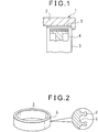
- FIG. 1 shows a drum brake.
- a brake drum 3 is attached by insert casting.
- the wheel 1 is comprised of aluminum alloy or magnesium alloy, while the brake drum 3 is formed by cast iron, cast steel, or an aluminum alloy.
- Reference numeral 4 is a brake shoe having the action of being pressed against the inner circumference of the brake drum 3.
- a plurality of projections 6 are formed over the entire area. Among these projections 6, part or all of the projections 6 have thin-waisted shapes.
- the height of the projections 6 is 0.3 to 5.0 mm, while the number of the projections 6 is 5 to 100/cm 2 .
- the height of the projections 6 is less than 0.3 mm, the drag strength in the rotational direction becomes insufficient, while if over 5.0 mm, the effect of reduction of thickness is lost. If the number of the projections 6 is less than 5/cm 2 , the drag strength in the rotational direction becomes insufficient, while if over 100/cm 2 , the castability becomes poor.
- the brake drum 3 is produced by centrifugal casting. Below, the method of production of the brake drum 3 will be explained.
- Diatomaceous earth, bentonite (binder), water, and a surfactant are mixed in a predetermined ratio to prepare a mold wash.
- the mold wash is spray coated on the inside surface of a casting mold (mold) which is heated to 200 to 400°C and rotates whereby a mold wash layer is formed on the inside surface of the casting mold. Due to the action of the surfactant, a plurality of recessed holes are formed in the mold wash layer due to the bubbles of the gas produced from the inside of the mold wash layer.
- the mold wash layer is dried, then metal melt is cast into the rotating casting mold. At this time, the melt fills the recessed holes of the mold wash layer whereby a plurality of uniform projections are formed.
- the melt hardens to form the brake drum then the brake drum is taken out from the casting mold together with the mold wash layer. This is then blasted to remove the mold wash whereby a brake drum which has a plurality of projections, at least part of which projections have a thin-waisted shape, over its entire outer circumferential surface is produced.
- FIG. 5 is a view showing the relationship between the load and stroke (displacement) when applying a compressive load to a test piece by a universal tensile/compression tester.
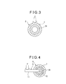
- FIG. 3 is a schematic view of a compression test.
- a test piece 8 formed by insert casting a brake drum 3A, made of cast iron and forming a cylindrical shape, at an inner circumference of a cylindrical member 7 made of aluminum alloy is measured for displacement-load up to fracture when applying a compressive load P from above by a load test machine.
- the pushing speed was 3 mm/min.
- the brake drum of the present invention used in the test had a height of projections of 0.6 to 0.75 mm and a number of projections of 10 to 29/cm 2 , while the brake drum of the comparative example was not formed with projections at its outer circumferential surface, had a maximum height Ry of relief shapes of the surface roughness of 100 to 250 ⁇ m, and had an average distance Sm of relief shapes of 0.7 to 1.4 mm.
- the compressive load is about 1.3 to 1.4 times higher in the present invention than the comparative example at displacements of 1.3 mm, 1.8 mm, and 2.3 mm.
- the fracture load is about 19kN in the present invention and about 12.5kN in the comparative example.
- the present invention has a fracture load about 1.5 times higher than the comparative example.
- FIG. 6 is a view showing the test results of the drag strength when applying a load to a test piece by a universal tensile/compression tester and twisting in the rotational direction.
- FIG. 4 is a schematic view of a drag strength test.
- the test piece 8 was formed by insert casting a brake drum 3B made of cast iron and forming a cylindrical shape at an inner circumference of a cylindrical member 7 made of aluminum alloy. At the inner circumference of the brake drum 3B, a plurality of recesses are formed at intervals in the peripheral direction.
- the fixture 9 to which the test piece 8 is attached has a main body 10 attached to the inner circumference of the brake drum 3B of the test piece 8.
- the fixture 9 has an arm 11 which is fastened to the center part of the side surface of the main body 10 and extends to the side.
- the test piece 8 is set at the main body 10 of the fixture 9. Note that, a thin sleeve (not shown) is inserted into the clearance between the inner circumference of the brake drum 3B of the test piece 8 and the outer circumference of the main body 10 of the fixture 9.
- the test piece 8 is measured for load kg-m (drag strength) when applying a load P from above to the arm 11 (arm length 200 mm) of the fixture 9 by a load test machine in the fastened state and twisting the test piece 8 in the rotational direction.
- the pushing speed was 6 mm/min.
- the brake drum of the present invention used in the above test has a height of projections of 0.6 to 0.75 mm and a number of projections of 10 to 29/cm 2 .
- the brake drum of the comparative example is not formed with projections over the outer circumferential surface.
- the maximum height Ry of the relief shapes of the surface roughness was 100 to 250 ⁇ m, while the average distance Sm between relief shapes was 0.7 to 1.4 mm.
- FIG. 6 shows the relative values when indexed to the drag strength of the comparative example as "1". As shown in FIG. 6 , it is learned that the drag strength of the present invention is about 3.5 times higher than the comparative example.
Abstract
Description
- The present invention relates to a brake drum used for a drum brake of an automobile or motorcycle.
- As a brake drum, for example there is the one shown in Japanese Patent Publication (A) No.
2004-084889 - As related art, there is Japanese Patent Publication (A) No.
2004-084889 - However, in the brake drum shown in Japanese Patent Publication (A) No.
2004-084889 - An object of the present invention is to provide a brake drum which can be improved in drag strength, strength and rigidity in the diametrical direction, joint strength, and heat radiating ability.
- The present invention provides a brake drum which is used for a drum brake, wherein the drum has a plurality of the projections at the outer circumferential surface, the plurality of the projections are formed at the outer circumferential surface as a whole when casting a brake drum, and at least part of the projections have thin-waisted shapes.
- The height of the projections is preferably 0.3 to 5.0 mm, while the number of projections is preferably 5 to 100/cm2 .
- The brake drum is preferably made by cast iron, cast steel, or aluminum alloy.
- The brake drum is preferably produced by centrifugal casting.
- The brake drum is attached by insert casting to a member comprised of for example aluminum alloy or magnesium alloy.
- According to the brake drum of the present invention, the entire outer circumferential surface has a plurality of the projections, so the drag strength and heat radiating ability are improved. Further, the strength and rigidity in the diametrical direction are improved and abnormal noise is reduced. Further, by making part or all of the projections thin-waisted projections, the drag strength and joint strength are improved and greater thinness becomes possible.
- These and other objects and features of the present invention will become clearer from the following description of the preferred embodiments given with reference to the attached drawings, wherein:
-
FIG. 1 is a longitudinal cross-sectional view of an embodiment of the present invention; -
FIG. 2 is a perspective view of a brake drum; -
FIG. 3 is a schematic view of a compression test; -
FIG. 4 is a schematic view of a drag strength test; -
FIG. 5 is a graph showing the test results of the compression test; and -
FIG. 6 is a graph showing the test results of the drag strength test. - Below, preferred embodiments of the present invention will be explained while referring to the drawings.
-
FIG. 1 shows a drum brake. At the inner circumferential surface of a cylindrically shapeddrum part 2 of a wheel 1, abrake drum 3 is attached by insert casting. The wheel 1 is comprised of aluminum alloy or magnesium alloy, while thebrake drum 3 is formed by cast iron, cast steel, or an aluminum alloy.Reference numeral 4 is a brake shoe having the action of being pressed against the inner circumference of thebrake drum 3. - At the outer
circumferential surface 5 of the cylndrically shaped brake drum 3 (seeFIG. 2 ), a plurality ofprojections 6 are formed over the entire area. Among theseprojections 6, part or all of theprojections 6 have thin-waisted shapes. The height of theprojections 6 is 0.3 to 5.0 mm, while the number of theprojections 6 is 5 to 100/cm2. - If the height of the
projections 6 is less than 0.3 mm, the drag strength in the rotational direction becomes insufficient, while if over 5.0 mm, the effect of reduction of thickness is lost. If the number of theprojections 6 is less than 5/cm2, the drag strength in the rotational direction becomes insufficient, while if over 100/cm2, the castability becomes poor. - The
brake drum 3 is produced by centrifugal casting. Below, the method of production of thebrake drum 3 will be explained. - Diatomaceous earth, bentonite (binder), water, and a surfactant are mixed in a predetermined ratio to prepare a mold wash. The mold wash is spray coated on the inside surface of a casting mold (mold) which is heated to 200 to 400°C and rotates whereby a mold wash layer is formed on the inside surface of the casting mold. Due to the action of the surfactant, a plurality of recessed holes are formed in the mold wash layer due to the bubbles of the gas produced from the inside of the mold wash layer. The mold wash layer is dried, then metal melt is cast into the rotating casting mold. At this time, the melt fills the recessed holes of the mold wash layer whereby a plurality of uniform projections are formed. The melt hardens to form the brake drum, then the brake drum is taken out from the casting mold together with the mold wash layer. This is then blasted to remove the mold wash whereby a brake drum which has a plurality of projections, at least part of which projections have a thin-waisted shape, over its entire outer circumferential surface is produced.
-
FIG. 5 is a view showing the relationship between the load and stroke (displacement) when applying a compressive load to a test piece by a universal tensile/compression tester.FIG. 3 is a schematic view of a compression test. Atest piece 8 formed by insert casting a brake drum 3A, made of cast iron and forming a cylindrical shape, at an inner circumference of a cylindrical member 7 made of aluminum alloy is measured for displacement-load up to fracture when applying a compressive load P from above by a load test machine. The pushing speed was 3 mm/min. - The brake drum of the present invention used in the test had a height of projections of 0.6 to 0.75 mm and a number of projections of 10 to 29/cm2, while the brake drum of the comparative example was not formed with projections at its outer circumferential surface, had a maximum height Ry of relief shapes of the surface roughness of 100 to 250 µm, and had an average distance Sm of relief shapes of 0.7 to 1.4 mm.
- As shown in
FIG. 5 , the compressive load is about 1.3 to 1.4 times higher in the present invention than the comparative example at displacements of 1.3 mm, 1.8 mm, and 2.3 mm. Further, the fracture load is about 19kN in the present invention and about 12.5kN in the comparative example. The present invention has a fracture load about 1.5 times higher than the comparative example. -
FIG. 6 is a view showing the test results of the drag strength when applying a load to a test piece by a universal tensile/compression tester and twisting in the rotational direction.FIG. 4 is a schematic view of a drag strength test. Thetest piece 8 was formed by insert casting abrake drum 3B made of cast iron and forming a cylindrical shape at an inner circumference of a cylindrical member 7 made of aluminum alloy. At the inner circumference of thebrake drum 3B, a plurality of recesses are formed at intervals in the peripheral direction. Thefixture 9 to which thetest piece 8 is attached has amain body 10 attached to the inner circumference of thebrake drum 3B of thetest piece 8. At the outer circumference of themain body 10, a plurality of teeth are formed while fit into the recesses of the inner circumference of thebrake drum 3B. Thefixture 9 has anarm 11 which is fastened to the center part of the side surface of themain body 10 and extends to the side. - The
test piece 8 is set at themain body 10 of thefixture 9. Note that, a thin sleeve (not shown) is inserted into the clearance between the inner circumference of thebrake drum 3B of thetest piece 8 and the outer circumference of themain body 10 of thefixture 9. Thetest piece 8 is measured for load kg-m (drag strength) when applying a load P from above to the arm 11 (arm length 200 mm) of thefixture 9 by a load test machine in the fastened state and twisting thetest piece 8 in the rotational direction. The pushing speed was 6 mm/min. - The brake drum of the present invention used in the above test has a height of projections of 0.6 to 0.75 mm and a number of projections of 10 to 29/cm2. The brake drum of the comparative example is not formed with projections over the outer circumferential surface. The maximum height Ry of the relief shapes of the surface roughness was 100 to 250 µm, while the average distance Sm between relief shapes was 0.7 to 1.4 mm.
-
FIG. 6 shows the relative values when indexed to the drag strength of the comparative example as "1". As shown inFIG. 6 , it is learned that the drag strength of the present invention is about 3.5 times higher than the comparative example. - While the invention has been described with reference to specific embodiments chosen for purpose of illustration, it should be apparent that numerous modifications could be made thereto by those skilled in the art without departing from the basic concept and scope of the invention.
Claims (5)
- A brake drum which is used for a drum brake, wherein the drum has a plurality of the projections at the outer circumferential surface, said plurality of the projections are formed at the outer circumferential surface as a whole when casting a brake drum, and at least part of the projections have thin-waisted shapes.
- A brake drum as set forth in clam 1, wherein a height of the projections is 0.3 to 5.0 mm, while the number of projections is 5 to 100/cm2.
- A brake drum as set forth in claim 1 or 2, wherein said brake drum is made by cast iron, cast steel, or aluminum alloy.
- A brake drum as set forth in claim 1, 2, or 3, wherein the brake drum is produced by centrifugal casting.
- A brake drum as set forth in any one of claims 1 to 4, wherein said brake drum is attached by insert casting to a member comprised of aluminum alloy or magnesium alloy.
Applications Claiming Priority (1)
| Application Number | Priority Date | Filing Date | Title |
|---|---|---|---|
| JP2011048822A JP2012184810A (en) | 2011-03-07 | 2011-03-07 | Brake drum |
Publications (2)
| Publication Number | Publication Date |
|---|---|
| EP2497967A1 true EP2497967A1 (en) | 2012-09-12 |
| EP2497967B1 EP2497967B1 (en) | 2013-07-31 |
Family
ID=45655586
Family Applications (1)
| Application Number | Title | Priority Date | Filing Date |
|---|---|---|---|
| EP20120154919 Active EP2497967B1 (en) | 2011-03-07 | 2012-02-10 | Brake drum |
Country Status (7)
| Country | Link |
|---|---|
| US (1) | US8905202B2 (en) |
| EP (1) | EP2497967B1 (en) |
| JP (1) | JP2012184810A (en) |
| KR (1) | KR101618140B1 (en) |
| CN (1) | CN102678792B (en) |
| BR (1) | BR102012005093A2 (en) |
| IN (1) | IN2012DE00651A (en) |
Cited By (2)
| Publication number | Priority date | Publication date | Assignee | Title |
|---|---|---|---|---|
| FR3100296A1 (en) | 2019-09-02 | 2021-03-05 | Bronze Alu | Composite brake drum |
| WO2023166141A1 (en) * | 2022-03-03 | 2023-09-07 | Bergmann Automotive GmbH | Friction ring for a brake drum of a drum brake of a vehicle, brake drum of a drum brake of a vehicle, vehicle, use of a friction ring for a brake drum of a drum brake of a vehicle, and method for producing a friction ring |
Families Citing this family (2)
| Publication number | Priority date | Publication date | Assignee | Title |
|---|---|---|---|---|
| WO2015002289A1 (en) * | 2013-07-05 | 2015-01-08 | Tpr株式会社 | Rotary body shaft, rotary body structure, and vehicle wheel |
| CN103644222A (en) * | 2013-11-28 | 2014-03-19 | 泉州市泰达车轮设备有限公司 | Double-metal heat dissipation type brake drum and machining method thereof |
Citations (3)
| Publication number | Priority date | Publication date | Assignee | Title |
|---|---|---|---|---|
| US3888296A (en) * | 1974-05-30 | 1975-06-10 | Gen Motors Corp | Method for the manufacture of a composite article |
| US20040026189A1 (en) * | 2002-07-11 | 2004-02-12 | Nsk-Warner K.K. | Brake drum for wet-type band brake drum and method for manufacturing the same |
| JP2004084889A (en) | 2002-08-28 | 2004-03-18 | Honda Motor Co Ltd | Brake drum made of aluminum group composite material and manufacturing method of the same |
Family Cites Families (22)
| Publication number | Priority date | Publication date | Assignee | Title |
|---|---|---|---|---|
| US1947091A (en) * | 1927-06-28 | 1934-02-13 | Charles G Keller | Brake |
| US1989211A (en) * | 1930-11-21 | 1935-01-29 | Bendix Brake Co | Composite brake drum |
| US1927306A (en) * | 1931-06-08 | 1933-09-19 | Campbell Wyant & Cannon Co | Composite brake drum |
| US2042654A (en) * | 1932-06-20 | 1936-06-02 | Kelsey Hayes Wheel Co | Brake drum |
| US2173591A (en) * | 1936-04-29 | 1939-09-19 | Bendix Prod Corp | Brake drum |
| JPH0480938A (en) | 1990-07-24 | 1992-03-13 | Fujitsu Ltd | Inspection of soi substrate |
| JPH0480938U (en) * | 1990-11-22 | 1992-07-14 | ||
| HUT60020A (en) * | 1990-12-07 | 1992-07-28 | Budd Co | Brake drum provided with reinforcing part-unit particularly for motor vehicles and method for producing same |
| JPH05187466A (en) * | 1992-01-08 | 1993-07-27 | Toyota Motor Corp | Brake drum |
| US5806636A (en) * | 1995-08-16 | 1998-09-15 | Northrop Grumman Corporation | Brake rotors/drums and brake pads particulary adapted for motorized vehicles |
| JPH11336803A (en) * | 1998-05-22 | 1999-12-07 | Aisin Takaoka Ltd | Brake drum |
| WO2001092750A1 (en) * | 2000-05-29 | 2001-12-06 | Honda Giken Kogyo Kabushiki Kaisha | Brake drum and method for producing the same |
| JP3719387B2 (en) * | 2001-02-23 | 2005-11-24 | 本田技研工業株式会社 | Mold release agent for centrifugal casting mold |
| CN2512945Y (en) * | 2001-12-08 | 2002-09-25 | 任士有 | Automobile brake drum with radiation reinforced rib and measuring hole |
| CN2522669Y (en) * | 2002-01-23 | 2002-11-27 | 杨扬 | Apertured braking drum |
| JP3962276B2 (en) * | 2002-04-12 | 2007-08-22 | アイシン高丘株式会社 | Brake drum manufacturing method |
| JP4429025B2 (en) * | 2004-01-09 | 2010-03-10 | トヨタ自動車株式会社 | Cylinder liner for casting |
| CN2695718Y (en) * | 2004-04-20 | 2005-04-27 | 龙岩畅丰机械制造有限公司 | Bi-metal brake drum |
| CN2736596Y (en) * | 2004-10-15 | 2005-10-26 | 杨东洲 | Forced radiation automotive brake drum |
| JP5388475B2 (en) * | 2008-04-30 | 2014-01-15 | Tpr株式会社 | Casting structure |
| JP2010133424A (en) * | 2010-02-22 | 2010-06-17 | Toyota Motor Corp | Method of manufacturing cylinder liner |
| JP4975131B2 (en) * | 2010-03-30 | 2012-07-11 | トヨタ自動車株式会社 | Cylinder liner manufacturing method |
-
2011
- 2011-03-07 JP JP2011048822A patent/JP2012184810A/en active Pending
-
2012
- 2012-02-10 EP EP20120154919 patent/EP2497967B1/en active Active
- 2012-03-02 CN CN201210142279.8A patent/CN102678792B/en active Active
- 2012-03-06 KR KR1020120022705A patent/KR101618140B1/en active IP Right Grant
- 2012-03-06 US US13/413,224 patent/US8905202B2/en active Active
- 2012-03-06 IN IN651DE2012 patent/IN2012DE00651A/en unknown
- 2012-03-07 BR BR102012005093A patent/BR102012005093A2/en not_active IP Right Cessation
Patent Citations (3)
| Publication number | Priority date | Publication date | Assignee | Title |
|---|---|---|---|---|
| US3888296A (en) * | 1974-05-30 | 1975-06-10 | Gen Motors Corp | Method for the manufacture of a composite article |
| US20040026189A1 (en) * | 2002-07-11 | 2004-02-12 | Nsk-Warner K.K. | Brake drum for wet-type band brake drum and method for manufacturing the same |
| JP2004084889A (en) | 2002-08-28 | 2004-03-18 | Honda Motor Co Ltd | Brake drum made of aluminum group composite material and manufacturing method of the same |
Cited By (4)
| Publication number | Priority date | Publication date | Assignee | Title |
|---|---|---|---|---|
| FR3100296A1 (en) | 2019-09-02 | 2021-03-05 | Bronze Alu | Composite brake drum |
| WO2021043836A1 (en) | 2019-09-02 | 2021-03-11 | Bronze Alu | Composite brake drum |
| WO2023166141A1 (en) * | 2022-03-03 | 2023-09-07 | Bergmann Automotive GmbH | Friction ring for a brake drum of a drum brake of a vehicle, brake drum of a drum brake of a vehicle, vehicle, use of a friction ring for a brake drum of a drum brake of a vehicle, and method for producing a friction ring |
| DE102022105044A1 (en) | 2022-03-03 | 2023-09-07 | Bergmann Automotive GmbH | Friction ring for a brake drum of a drum brake of a vehicle, brake drum of a drum brake of a vehicle, vehicle, use of a friction ring for a brake drum of a drum brake of a vehicle and method for producing a friction ring |
Also Published As
| Publication number | Publication date |
|---|---|
| KR20120102012A (en) | 2012-09-17 |
| JP2012184810A (en) | 2012-09-27 |
| KR101618140B1 (en) | 2016-05-04 |
| EP2497967B1 (en) | 2013-07-31 |
| BR102012005093A2 (en) | 2013-07-23 |
| US8905202B2 (en) | 2014-12-09 |
| IN2012DE00651A (en) | 2015-07-24 |
| CN102678792B (en) | 2016-08-17 |
| CN102678792A (en) | 2012-09-19 |
| US20120228068A1 (en) | 2012-09-13 |
Similar Documents
| Publication | Publication Date | Title |
|---|---|---|
| EP2497967B1 (en) | Brake drum | |
| JP4241627B2 (en) | Cylinder liner and cylinder block | |
| JP5579106B2 (en) | Support member | |
| JP4210468B2 (en) | Cast iron cast-in member | |
| JP2012184778A5 (en) | ||
| US20140332329A1 (en) | Brake rotor and method of manufacturing the same | |
| US20170107933A1 (en) | Cylinder liner | |
| EP2273148A1 (en) | Drum wear indicator | |
| US9163682B2 (en) | Friction damped brake drum | |
| CN102322490A (en) | Manufacturing method of brake drum of duplex metal composite automobile | |
| AU2015204340B2 (en) | Connecting rod for internal combustion engine | |
| RU2017100305A (en) | DISK BRAKE WITH EXCITATION RING | |
| US20130323525A1 (en) | Refractory interface coating for bi-metallic automotive products and method | |
| JP5789312B2 (en) | Assembly processing method using protective clip and caliper body | |
| JP2012067717A (en) | Cylinder liner and manufacturing method thereof | |
| CN110637172B (en) | Brake drum and method for manufacturing such a brake drum | |
| KR102434875B1 (en) | Friction rings for brake discs, brake discs and corresponding manufacturing methods | |
| JP2015180839A (en) | brake drum | |
| JP2002372130A (en) | Pulley for clutch-less compressor, and clutch-less compressor | |
| EP3147529B1 (en) | Disc brake disc and method of making such disc | |
| JP2017519955A (en) | Brake disc and brake device for automobile | |
| CN107377944B (en) | Cast-in member | |
| JP2013032845A (en) | Support member | |
| JP5678779B2 (en) | Cylinder liner and cylinder block including the same | |
| JP2013027936A (en) | Support member |
Legal Events
| Date | Code | Title | Description |
|---|---|---|---|
| PUAI | Public reference made under article 153(3) epc to a published international application that has entered the european phase |
Free format text: ORIGINAL CODE: 0009012 |
|
| AK | Designated contracting states |
Kind code of ref document: A1 Designated state(s): AL AT BE BG CH CY CZ DE DK EE ES FI FR GB GR HR HU IE IS IT LI LT LU LV MC MK MT NL NO PL PT RO RS SE SI SK SM TR |
|
| AX | Request for extension of the european patent |
Extension state: BA ME |
|
| 17P | Request for examination filed |
Effective date: 20120907 |
|
| GRAP | Despatch of communication of intention to grant a patent |
Free format text: ORIGINAL CODE: EPIDOSNIGR1 |
|
| GRAS | Grant fee paid |
Free format text: ORIGINAL CODE: EPIDOSNIGR3 |
|
| GRAA | (expected) grant |
Free format text: ORIGINAL CODE: 0009210 |
|
| AK | Designated contracting states |
Kind code of ref document: B1 Designated state(s): AL AT BE BG CH CY CZ DE DK EE ES FI FR GB GR HR HU IE IS IT LI LT LU LV MC MK MT NL NO PL PT RO RS SE SI SK SM TR |
|
| REG | Reference to a national code |
Ref country code: GB Ref legal event code: FG4D Ref country code: CH Ref legal event code: EP |
|
| REG | Reference to a national code |
Ref country code: AT Ref legal event code: REF Ref document number: 624840 Country of ref document: AT Kind code of ref document: T Effective date: 20130815 |
|
| REG | Reference to a national code |
Ref country code: IE Ref legal event code: FG4D |
|
| REG | Reference to a national code |
Ref country code: DE Ref legal event code: R096 Ref document number: 602012000170 Country of ref document: DE Effective date: 20130926 |
|
| REG | Reference to a national code |
Ref country code: AT Ref legal event code: MK05 Ref document number: 624840 Country of ref document: AT Kind code of ref document: T Effective date: 20130731 |
|
| REG | Reference to a national code |
Ref country code: NL Ref legal event code: VDEP Effective date: 20130731 |
|
| REG | Reference to a national code |
Ref country code: LT Ref legal event code: MG4D |
|
| PG25 | Lapsed in a contracting state [announced via postgrant information from national office to epo] |
Ref country code: IS Free format text: LAPSE BECAUSE OF FAILURE TO SUBMIT A TRANSLATION OF THE DESCRIPTION OR TO PAY THE FEE WITHIN THE PRESCRIBED TIME-LIMIT Effective date: 20131130 Ref country code: SE Free format text: LAPSE BECAUSE OF FAILURE TO SUBMIT A TRANSLATION OF THE DESCRIPTION OR TO PAY THE FEE WITHIN THE PRESCRIBED TIME-LIMIT Effective date: 20130731 Ref country code: AT Free format text: LAPSE BECAUSE OF FAILURE TO SUBMIT A TRANSLATION OF THE DESCRIPTION OR TO PAY THE FEE WITHIN THE PRESCRIBED TIME-LIMIT Effective date: 20130731 Ref country code: PT Free format text: LAPSE BECAUSE OF FAILURE TO SUBMIT A TRANSLATION OF THE DESCRIPTION OR TO PAY THE FEE WITHIN THE PRESCRIBED TIME-LIMIT Effective date: 20131202 Ref country code: HR Free format text: LAPSE BECAUSE OF FAILURE TO SUBMIT A TRANSLATION OF THE DESCRIPTION OR TO PAY THE FEE WITHIN THE PRESCRIBED TIME-LIMIT Effective date: 20130731 Ref country code: CY Free format text: LAPSE BECAUSE OF FAILURE TO SUBMIT A TRANSLATION OF THE DESCRIPTION OR TO PAY THE FEE WITHIN THE PRESCRIBED TIME-LIMIT Effective date: 20130911 Ref country code: LT Free format text: LAPSE BECAUSE OF FAILURE TO SUBMIT A TRANSLATION OF THE DESCRIPTION OR TO PAY THE FEE WITHIN THE PRESCRIBED TIME-LIMIT Effective date: 20130731 Ref country code: BE Free format text: LAPSE BECAUSE OF FAILURE TO SUBMIT A TRANSLATION OF THE DESCRIPTION OR TO PAY THE FEE WITHIN THE PRESCRIBED TIME-LIMIT Effective date: 20130731 Ref country code: NO Free format text: LAPSE BECAUSE OF FAILURE TO SUBMIT A TRANSLATION OF THE DESCRIPTION OR TO PAY THE FEE WITHIN THE PRESCRIBED TIME-LIMIT Effective date: 20131031 |
|
| RIN2 | Information on inventor provided after grant (corrected) |
Inventor name: NOBE, TAKAHIRO Inventor name: OZAWA, SHINGO |
|
| PG25 | Lapsed in a contracting state [announced via postgrant information from national office to epo] |
Ref country code: NL Free format text: LAPSE BECAUSE OF FAILURE TO SUBMIT A TRANSLATION OF THE DESCRIPTION OR TO PAY THE FEE WITHIN THE PRESCRIBED TIME-LIMIT Effective date: 20130731 Ref country code: PL Free format text: LAPSE BECAUSE OF FAILURE TO SUBMIT A TRANSLATION OF THE DESCRIPTION OR TO PAY THE FEE WITHIN THE PRESCRIBED TIME-LIMIT Effective date: 20130731 Ref country code: LV Free format text: LAPSE BECAUSE OF FAILURE TO SUBMIT A TRANSLATION OF THE DESCRIPTION OR TO PAY THE FEE WITHIN THE PRESCRIBED TIME-LIMIT Effective date: 20130731 Ref country code: SI Free format text: LAPSE BECAUSE OF FAILURE TO SUBMIT A TRANSLATION OF THE DESCRIPTION OR TO PAY THE FEE WITHIN THE PRESCRIBED TIME-LIMIT Effective date: 20130731 Ref country code: FI Free format text: LAPSE BECAUSE OF FAILURE TO SUBMIT A TRANSLATION OF THE DESCRIPTION OR TO PAY THE FEE WITHIN THE PRESCRIBED TIME-LIMIT Effective date: 20130731 Ref country code: GR Free format text: LAPSE BECAUSE OF FAILURE TO SUBMIT A TRANSLATION OF THE DESCRIPTION OR TO PAY THE FEE WITHIN THE PRESCRIBED TIME-LIMIT Effective date: 20131101 |
|
| PG25 | Lapsed in a contracting state [announced via postgrant information from national office to epo] |
Ref country code: CY Free format text: LAPSE BECAUSE OF FAILURE TO SUBMIT A TRANSLATION OF THE DESCRIPTION OR TO PAY THE FEE WITHIN THE PRESCRIBED TIME-LIMIT Effective date: 20130731 |
|
| PG25 | Lapsed in a contracting state [announced via postgrant information from national office to epo] |
Ref country code: SK Free format text: LAPSE BECAUSE OF FAILURE TO SUBMIT A TRANSLATION OF THE DESCRIPTION OR TO PAY THE FEE WITHIN THE PRESCRIBED TIME-LIMIT Effective date: 20130731 Ref country code: RO Free format text: LAPSE BECAUSE OF FAILURE TO SUBMIT A TRANSLATION OF THE DESCRIPTION OR TO PAY THE FEE WITHIN THE PRESCRIBED TIME-LIMIT Effective date: 20130731 Ref country code: EE Free format text: LAPSE BECAUSE OF FAILURE TO SUBMIT A TRANSLATION OF THE DESCRIPTION OR TO PAY THE FEE WITHIN THE PRESCRIBED TIME-LIMIT Effective date: 20130731 Ref country code: CZ Free format text: LAPSE BECAUSE OF FAILURE TO SUBMIT A TRANSLATION OF THE DESCRIPTION OR TO PAY THE FEE WITHIN THE PRESCRIBED TIME-LIMIT Effective date: 20130731 Ref country code: DK Free format text: LAPSE BECAUSE OF FAILURE TO SUBMIT A TRANSLATION OF THE DESCRIPTION OR TO PAY THE FEE WITHIN THE PRESCRIBED TIME-LIMIT Effective date: 20130731 |
|
| PG25 | Lapsed in a contracting state [announced via postgrant information from national office to epo] |
Ref country code: ES Free format text: LAPSE BECAUSE OF FAILURE TO SUBMIT A TRANSLATION OF THE DESCRIPTION OR TO PAY THE FEE WITHIN THE PRESCRIBED TIME-LIMIT Effective date: 20130731 Ref country code: IT Free format text: LAPSE BECAUSE OF FAILURE TO SUBMIT A TRANSLATION OF THE DESCRIPTION OR TO PAY THE FEE WITHIN THE PRESCRIBED TIME-LIMIT Effective date: 20130731 |
|
| PLBE | No opposition filed within time limit |
Free format text: ORIGINAL CODE: 0009261 |
|
| STAA | Information on the status of an ep patent application or granted ep patent |
Free format text: STATUS: NO OPPOSITION FILED WITHIN TIME LIMIT |
|
| 26N | No opposition filed |
Effective date: 20140502 |
|
| REG | Reference to a national code |
Ref country code: DE Ref legal event code: R097 Ref document number: 602012000170 Country of ref document: DE Effective date: 20140502 |
|
| PG25 | Lapsed in a contracting state [announced via postgrant information from national office to epo] |
Ref country code: MC Free format text: LAPSE BECAUSE OF FAILURE TO SUBMIT A TRANSLATION OF THE DESCRIPTION OR TO PAY THE FEE WITHIN THE PRESCRIBED TIME-LIMIT Effective date: 20130731 Ref country code: LU Free format text: LAPSE BECAUSE OF FAILURE TO SUBMIT A TRANSLATION OF THE DESCRIPTION OR TO PAY THE FEE WITHIN THE PRESCRIBED TIME-LIMIT Effective date: 20140210 |
|
| REG | Reference to a national code |
Ref country code: FR Ref legal event code: ST Effective date: 20141031 |
|
| REG | Reference to a national code |
Ref country code: IE Ref legal event code: MM4A |
|
| PG25 | Lapsed in a contracting state [announced via postgrant information from national office to epo] |
Ref country code: FR Free format text: LAPSE BECAUSE OF NON-PAYMENT OF DUE FEES Effective date: 20140228 Ref country code: IE Free format text: LAPSE BECAUSE OF NON-PAYMENT OF DUE FEES Effective date: 20140210 |
|
| REG | Reference to a national code |
Ref country code: CH Ref legal event code: PL |
|
| PG25 | Lapsed in a contracting state [announced via postgrant information from national office to epo] |
Ref country code: LI Free format text: LAPSE BECAUSE OF NON-PAYMENT OF DUE FEES Effective date: 20150228 Ref country code: CH Free format text: LAPSE BECAUSE OF NON-PAYMENT OF DUE FEES Effective date: 20150228 |
|
| PG25 | Lapsed in a contracting state [announced via postgrant information from national office to epo] |
Ref country code: MT Free format text: LAPSE BECAUSE OF FAILURE TO SUBMIT A TRANSLATION OF THE DESCRIPTION OR TO PAY THE FEE WITHIN THE PRESCRIBED TIME-LIMIT Effective date: 20130731 |
|
| PG25 | Lapsed in a contracting state [announced via postgrant information from national office to epo] |
Ref country code: SM Free format text: LAPSE BECAUSE OF FAILURE TO SUBMIT A TRANSLATION OF THE DESCRIPTION OR TO PAY THE FEE WITHIN THE PRESCRIBED TIME-LIMIT Effective date: 20130731 |
|
| PG25 | Lapsed in a contracting state [announced via postgrant information from national office to epo] |
Ref country code: BG Free format text: LAPSE BECAUSE OF FAILURE TO SUBMIT A TRANSLATION OF THE DESCRIPTION OR TO PAY THE FEE WITHIN THE PRESCRIBED TIME-LIMIT Effective date: 20130731 Ref country code: RS Free format text: LAPSE BECAUSE OF FAILURE TO SUBMIT A TRANSLATION OF THE DESCRIPTION OR TO PAY THE FEE WITHIN THE PRESCRIBED TIME-LIMIT Effective date: 20130731 |
|
| PG25 | Lapsed in a contracting state [announced via postgrant information from national office to epo] |
Ref country code: TR Free format text: LAPSE BECAUSE OF FAILURE TO SUBMIT A TRANSLATION OF THE DESCRIPTION OR TO PAY THE FEE WITHIN THE PRESCRIBED TIME-LIMIT Effective date: 20130731 Ref country code: HU Free format text: LAPSE BECAUSE OF FAILURE TO SUBMIT A TRANSLATION OF THE DESCRIPTION OR TO PAY THE FEE WITHIN THE PRESCRIBED TIME-LIMIT; INVALID AB INITIO Effective date: 20120210 |
|
| GBPC | Gb: european patent ceased through non-payment of renewal fee |
Effective date: 20160210 |
|
| PG25 | Lapsed in a contracting state [announced via postgrant information from national office to epo] |
Ref country code: GB Free format text: LAPSE BECAUSE OF NON-PAYMENT OF DUE FEES Effective date: 20160210 |
|
| PG25 | Lapsed in a contracting state [announced via postgrant information from national office to epo] |
Ref country code: MK Free format text: LAPSE BECAUSE OF FAILURE TO SUBMIT A TRANSLATION OF THE DESCRIPTION OR TO PAY THE FEE WITHIN THE PRESCRIBED TIME-LIMIT Effective date: 20130731 |
|
| PG25 | Lapsed in a contracting state [announced via postgrant information from national office to epo] |
Ref country code: AL Free format text: LAPSE BECAUSE OF FAILURE TO SUBMIT A TRANSLATION OF THE DESCRIPTION OR TO PAY THE FEE WITHIN THE PRESCRIBED TIME-LIMIT Effective date: 20130731 |
|
| PGFP | Annual fee paid to national office [announced via postgrant information from national office to epo] |
Ref country code: DE Payment date: 20240219 Year of fee payment: 13 |