EP2497925A1 - Intake apparatus of engine - Google Patents
Intake apparatus of engine Download PDFInfo
- Publication number
- EP2497925A1 EP2497925A1 EP10828189A EP10828189A EP2497925A1 EP 2497925 A1 EP2497925 A1 EP 2497925A1 EP 10828189 A EP10828189 A EP 10828189A EP 10828189 A EP10828189 A EP 10828189A EP 2497925 A1 EP2497925 A1 EP 2497925A1
- Authority
- EP
- European Patent Office
- Prior art keywords
- intake
- valve
- passage
- intake valve
- engine
- Prior art date
- Legal status (The legal status is an assumption and is not a legal conclusion. Google has not performed a legal analysis and makes no representation as to the accuracy of the status listed.)
- Granted
Links
- 239000000446 fuel Substances 0.000 claims description 45
- 238000002347 injection Methods 0.000 claims description 22
- 239000007924 injection Substances 0.000 claims description 22
- 239000000203 mixture Substances 0.000 description 21
- 238000002485 combustion reaction Methods 0.000 description 15
- 230000006835 compression Effects 0.000 description 10
- 238000007906 compression Methods 0.000 description 10
- 238000005086 pumping Methods 0.000 description 7
- 230000001737 promoting effect Effects 0.000 description 5
- 230000000694 effects Effects 0.000 description 3
- 238000000889 atomisation Methods 0.000 description 1
- 230000002238 attenuated effect Effects 0.000 description 1
- 230000004048 modification Effects 0.000 description 1
- 238000012986 modification Methods 0.000 description 1
- 230000000979 retarding effect Effects 0.000 description 1
- 238000010008 shearing Methods 0.000 description 1
- 239000007921 spray Substances 0.000 description 1
- 238000009834 vaporization Methods 0.000 description 1
- 230000008016 vaporization Effects 0.000 description 1
Images


Classifications
-
- F—MECHANICAL ENGINEERING; LIGHTING; HEATING; WEAPONS; BLASTING
- F02—COMBUSTION ENGINES; HOT-GAS OR COMBUSTION-PRODUCT ENGINE PLANTS
- F02D—CONTROLLING COMBUSTION ENGINES
- F02D13/00—Controlling the engine output power by varying inlet or exhaust valve operating characteristics, e.g. timing
- F02D13/02—Controlling the engine output power by varying inlet or exhaust valve operating characteristics, e.g. timing during engine operation
- F02D13/0223—Variable control of the intake valves only
- F02D13/0226—Variable control of the intake valves only changing valve lift or valve lift and timing
-
- F—MECHANICAL ENGINEERING; LIGHTING; HEATING; WEAPONS; BLASTING
- F01—MACHINES OR ENGINES IN GENERAL; ENGINE PLANTS IN GENERAL; STEAM ENGINES
- F01L—CYCLICALLY OPERATING VALVES FOR MACHINES OR ENGINES
- F01L1/00—Valve-gear or valve arrangements, e.g. lift-valve gear
- F01L1/12—Transmitting gear between valve drive and valve
- F01L1/18—Rocking arms or levers
- F01L1/181—Centre pivot rocking arms
-
- F—MECHANICAL ENGINEERING; LIGHTING; HEATING; WEAPONS; BLASTING
- F01—MACHINES OR ENGINES IN GENERAL; ENGINE PLANTS IN GENERAL; STEAM ENGINES
- F01L—CYCLICALLY OPERATING VALVES FOR MACHINES OR ENGINES
- F01L3/00—Lift-valve, i.e. cut-off apparatus with closure members having at least a component of their opening and closing motion perpendicular to the closing faces; Parts or accessories thereof
- F01L3/06—Valve members or valve-seats with means for guiding or deflecting the medium controlled thereby, e.g. producing a rotary motion of the drawn-in cylinder charge
-
- F—MECHANICAL ENGINEERING; LIGHTING; HEATING; WEAPONS; BLASTING
- F02—COMBUSTION ENGINES; HOT-GAS OR COMBUSTION-PRODUCT ENGINE PLANTS
- F02B—INTERNAL-COMBUSTION PISTON ENGINES; COMBUSTION ENGINES IN GENERAL
- F02B31/00—Modifying induction systems for imparting a rotation to the charge in the cylinder
- F02B31/08—Modifying induction systems for imparting a rotation to the charge in the cylinder having multiple air inlets
- F02B31/085—Modifying induction systems for imparting a rotation to the charge in the cylinder having multiple air inlets having two inlet valves
-
- F—MECHANICAL ENGINEERING; LIGHTING; HEATING; WEAPONS; BLASTING
- F02—COMBUSTION ENGINES; HOT-GAS OR COMBUSTION-PRODUCT ENGINE PLANTS
- F02D—CONTROLLING COMBUSTION ENGINES
- F02D13/00—Controlling the engine output power by varying inlet or exhaust valve operating characteristics, e.g. timing
- F02D13/02—Controlling the engine output power by varying inlet or exhaust valve operating characteristics, e.g. timing during engine operation
- F02D13/0257—Independent control of two or more intake or exhaust valves respectively, i.e. one of two intake valves remains closed or is opened partially while the other is fully opened
-
- F—MECHANICAL ENGINEERING; LIGHTING; HEATING; WEAPONS; BLASTING
- F02—COMBUSTION ENGINES; HOT-GAS OR COMBUSTION-PRODUCT ENGINE PLANTS
- F02D—CONTROLLING COMBUSTION ENGINES
- F02D41/00—Electrical control of supply of combustible mixture or its constituents
- F02D41/30—Controlling fuel injection
- F02D41/32—Controlling fuel injection of the low pressure type
- F02D41/34—Controlling fuel injection of the low pressure type with means for controlling injection timing or duration
- F02D41/345—Controlling injection timing
-
- F—MECHANICAL ENGINEERING; LIGHTING; HEATING; WEAPONS; BLASTING
- F01—MACHINES OR ENGINES IN GENERAL; ENGINE PLANTS IN GENERAL; STEAM ENGINES
- F01L—CYCLICALLY OPERATING VALVES FOR MACHINES OR ENGINES
- F01L1/00—Valve-gear or valve arrangements, e.g. lift-valve gear
- F01L1/12—Transmitting gear between valve drive and valve
- F01L1/18—Rocking arms or levers
- F01L1/185—Overhead end-pivot rocking arms
-
- F—MECHANICAL ENGINEERING; LIGHTING; HEATING; WEAPONS; BLASTING
- F01—MACHINES OR ENGINES IN GENERAL; ENGINE PLANTS IN GENERAL; STEAM ENGINES
- F01L—CYCLICALLY OPERATING VALVES FOR MACHINES OR ENGINES
- F01L1/00—Valve-gear or valve arrangements, e.g. lift-valve gear
- F01L1/20—Adjusting or compensating clearance
- F01L1/22—Adjusting or compensating clearance automatically, e.g. mechanically
- F01L1/24—Adjusting or compensating clearance automatically, e.g. mechanically by fluid means, e.g. hydraulically
- F01L1/2405—Adjusting or compensating clearance automatically, e.g. mechanically by fluid means, e.g. hydraulically by means of a hydraulic adjusting device located between the cylinder head and rocker arm
-
- F—MECHANICAL ENGINEERING; LIGHTING; HEATING; WEAPONS; BLASTING
- F01—MACHINES OR ENGINES IN GENERAL; ENGINE PLANTS IN GENERAL; STEAM ENGINES
- F01L—CYCLICALLY OPERATING VALVES FOR MACHINES OR ENGINES
- F01L1/00—Valve-gear or valve arrangements, e.g. lift-valve gear
- F01L1/34—Valve-gear or valve arrangements, e.g. lift-valve gear characterised by the provision of means for changing the timing of the valves without changing the duration of opening and without affecting the magnitude of the valve lift
- F01L1/344—Valve-gear or valve arrangements, e.g. lift-valve gear characterised by the provision of means for changing the timing of the valves without changing the duration of opening and without affecting the magnitude of the valve lift changing the angular relationship between crankshaft and camshaft, e.g. using helicoidal gear
-
- F—MECHANICAL ENGINEERING; LIGHTING; HEATING; WEAPONS; BLASTING
- F01—MACHINES OR ENGINES IN GENERAL; ENGINE PLANTS IN GENERAL; STEAM ENGINES
- F01L—CYCLICALLY OPERATING VALVES FOR MACHINES OR ENGINES
- F01L1/00—Valve-gear or valve arrangements, e.g. lift-valve gear
- F01L1/02—Valve drive
- F01L1/04—Valve drive by means of cams, camshafts, cam discs, eccentrics or the like
- F01L1/047—Camshafts
- F01L1/053—Camshafts overhead type
- F01L2001/0537—Double overhead camshafts [DOHC]
-
- F—MECHANICAL ENGINEERING; LIGHTING; HEATING; WEAPONS; BLASTING
- F01—MACHINES OR ENGINES IN GENERAL; ENGINE PLANTS IN GENERAL; STEAM ENGINES
- F01L—CYCLICALLY OPERATING VALVES FOR MACHINES OR ENGINES
- F01L2305/00—Valve arrangements comprising rollers
-
- F—MECHANICAL ENGINEERING; LIGHTING; HEATING; WEAPONS; BLASTING
- F01—MACHINES OR ENGINES IN GENERAL; ENGINE PLANTS IN GENERAL; STEAM ENGINES
- F01L—CYCLICALLY OPERATING VALVES FOR MACHINES OR ENGINES
- F01L2800/00—Methods of operation using a variable valve timing mechanism
- F01L2800/06—Timing or lift different for valves of same cylinder
-
- F—MECHANICAL ENGINEERING; LIGHTING; HEATING; WEAPONS; BLASTING
- F01—MACHINES OR ENGINES IN GENERAL; ENGINE PLANTS IN GENERAL; STEAM ENGINES
- F01N—GAS-FLOW SILENCERS OR EXHAUST APPARATUS FOR MACHINES OR ENGINES IN GENERAL; GAS-FLOW SILENCERS OR EXHAUST APPARATUS FOR INTERNAL COMBUSTION ENGINES
- F01N2240/00—Combination or association of two or more different exhaust treating devices, or of at least one such device with an auxiliary device, not covered by indexing codes F01N2230/00 or F01N2250/00, one of the devices being
- F01N2240/36—Combination or association of two or more different exhaust treating devices, or of at least one such device with an auxiliary device, not covered by indexing codes F01N2230/00 or F01N2250/00, one of the devices being an exhaust flap
-
- F—MECHANICAL ENGINEERING; LIGHTING; HEATING; WEAPONS; BLASTING
- F02—COMBUSTION ENGINES; HOT-GAS OR COMBUSTION-PRODUCT ENGINE PLANTS
- F02B—INTERNAL-COMBUSTION PISTON ENGINES; COMBUSTION ENGINES IN GENERAL
- F02B17/00—Engines characterised by means for effecting stratification of charge in cylinders
-
- F—MECHANICAL ENGINEERING; LIGHTING; HEATING; WEAPONS; BLASTING
- F02—COMBUSTION ENGINES; HOT-GAS OR COMBUSTION-PRODUCT ENGINE PLANTS
- F02M—SUPPLYING COMBUSTION ENGINES IN GENERAL WITH COMBUSTIBLE MIXTURES OR CONSTITUENTS THEREOF
- F02M35/00—Combustion-air cleaners, air intakes, intake silencers, or induction systems specially adapted for, or arranged on, internal-combustion engines
- F02M35/10—Air intakes; Induction systems
- F02M35/1015—Air intakes; Induction systems characterised by the engine type
- F02M35/10177—Engines having multiple fuel injectors or carburettors per cylinder
-
- Y—GENERAL TAGGING OF NEW TECHNOLOGICAL DEVELOPMENTS; GENERAL TAGGING OF CROSS-SECTIONAL TECHNOLOGIES SPANNING OVER SEVERAL SECTIONS OF THE IPC; TECHNICAL SUBJECTS COVERED BY FORMER USPC CROSS-REFERENCE ART COLLECTIONS [XRACs] AND DIGESTS
- Y02—TECHNOLOGIES OR APPLICATIONS FOR MITIGATION OR ADAPTATION AGAINST CLIMATE CHANGE
- Y02T—CLIMATE CHANGE MITIGATION TECHNOLOGIES RELATED TO TRANSPORTATION
- Y02T10/00—Road transport of goods or passengers
- Y02T10/10—Internal combustion engine [ICE] based vehicles
- Y02T10/12—Improving ICE efficiencies
-
- Y—GENERAL TAGGING OF NEW TECHNOLOGICAL DEVELOPMENTS; GENERAL TAGGING OF CROSS-SECTIONAL TECHNOLOGIES SPANNING OVER SEVERAL SECTIONS OF THE IPC; TECHNICAL SUBJECTS COVERED BY FORMER USPC CROSS-REFERENCE ART COLLECTIONS [XRACs] AND DIGESTS
- Y02—TECHNOLOGIES OR APPLICATIONS FOR MITIGATION OR ADAPTATION AGAINST CLIMATE CHANGE
- Y02T—CLIMATE CHANGE MITIGATION TECHNOLOGIES RELATED TO TRANSPORTATION
- Y02T10/00—Road transport of goods or passengers
- Y02T10/10—Internal combustion engine [ICE] based vehicles
- Y02T10/40—Engine management systems
Definitions
- the present invention relates to an intake apparatus of an engine using a high expansion ratio cycle.
- Patent Document 1 in the engine with the high expansion ratio cycle, the closing timing of an intake valve is retarded to make the expansion ratio higher than the compression ratio during the combustion cycle. This reduces the pump loss (pumping loss), which improves the heat efficiency and avoids knocking.
- Patent Document 1 Japanese Patent Application Publication No. 2004-183510
- the fuel-air mixture introduced to a cylinder is subject to the shearing stress by a change in a flow velocity, and then is compressed with turbulence generated.
- This turbulence uniformly spreads the fuel-air mixture in the cylinder, thereby ensuring the stable combustion.
- the intake valve continues opening until the middle of the compression stroke.
- the air-fuel mixture flows through the intake passage, so that the turbulence of the air-fuel mixture in the cylinder is dramatically attenuated.
- the turbulence of the air-fuel mixture in the cylinder is almost lost, which may arise a problem of the unstable combustion.
- an intake apparatus of an engine includes: a first intake passage supplying fresh air to a cylinder; a second intake passage arranged near the first intake passage, and supplying fresh air to the cylinder; a first intake valve opening and closing The first intake passage at an aperture of the first intake passage; and a second intake valve opening and closing the second intake passage at an aperture of the second intake passage, wherein an opening timing of the first intake valve advances relative to a top dead center, and a valve lift amount of the first intake valve differs from that of the second intake valve, and there is a period during which the valve lift amount of the first intake valve is larger than that of the second intake valve, in an intake stroke.
- the intake air flows out of the first intake passage with the first intake valve having a large lift amount toward the second intake passage with the second intake valve having a small lift amount.
- This outflow generates the rotational flow along an inner circumferential wall of the cylinder.
- this causes the introduced fresh air to flow out, thereby making the expansion ratio larger than the compression ratio in the cylinder.
- the fresh air flows through the second intake passage, so that an unbalance of the airflow occurs in the cylinder and then attenuation of the rotational flow is suppressed.
- attenuation of the rotational flow generated in the cylinder is suppressed with the pumping loss being reduced.
- the valve lift amount of the first intake valve may be larger than that of the second intake valve in a first half of the intake stroke.
- the first intake valve may open before the second intake valve opens. Therefore, the fresh air flows through the first intake passage and then generates the rotational flow, while the first intake valve is opening and the second intake valve is closing.
- the first intake valve may close before the second intake valve closes. Therefore, the fresh air flows through the second intake passage so as to maintain the rotational flow, while the first intake valve is closing and the second intake valve is opening.
- the above intake apparatus of the engine may include an introduction portion introducing rotational flow generated in the cylinder toward the second passage. This configuration increases the airflow velocity flowing through the second passage. This improves the rotational flow velocity in the cylinder, thereby suppressing attenuation of the rotational flow.
- the introduction portion may be a guide that is formed such that the rotational flow flows from a wall of the cylinder toward the second passage. This configuration suppresses the generation of the flow in such a direction as would attenuate the rotational flow of the gas flowing toward the second passage. This suppresses attenuation of the rotational flow, thereby promoting the mixture of the air and the fuel.
- the above intake apparatus of the engine may include a control valve opening and closing the second intake passage and arranged on the second intake passage, and the control valve may close in a period in which the first intake valve opens and the second intake valve opens, and the control valve may open in a period in which the first intake valve closes and the second intake valve opens.
- the air-fuel mixture is supplied only from the first intake passage to the cylinder in closing the control valve, thereby generating the unbalance of the airflow in the cylinder to generate the rotational flow.
- the air flows only through the second intake passage at the time of opening an opening/closing valve, thereby further promoting the unbalance of the air flow to suppress the rotational flow from attenuating.
- the rotational flow maintains the turbulence of the air-fuel mixture in the cylinder, thereby ensuring the stable combustion.
- the above intake apparatus of the engine may include a second passage injection valve injecting fuel to the second intake passage, and the second passage injection valve may inject the fuel when the second intake valve opens.
- the fuel is injected in the direction opposite to the direction in which the air flows from the cylinder to the second passage, thereby promoting the atomization of the fuel. This improves the combustion efficiency.
- the above intake apparatus of the engine may include: a first passage injection valve injecting fuel to the first intake passage; and a second passage injection valve injecting fuel to the second intake passage, the first passage injection valve may finish injection of the fuel before the first intake valve opens, and the second passage injection valve may inject the fuel when the second intake valve opens.
- This configuration reduces the air-fuel mixture to flow out at the time of the valve overlap.
- the first intake valve advances to open, whereby there is a period while the first intake valve overlaps an exhaust valve.
- the injection in the first intake passage is finished before the first intake valve opens in the present invention, thereby reducing the air-fuel mixture to flow out to the exhaust side. This improves the fuel consumption and the emission. Further, the fuel injected in the second passage side is atomized to improve the combustion efficiency.
- a control apparatus of an engine according to the present invention reduces the pumping loss, suppresses attenuation of the rotational flow generated in a cylinder, and promotes the mixture of air and fuel to form a stable combustion state.
- FIGS. 1A and 1B are explanatory views of an intake apparatus 10 of the first embodiment.
- FIG. 1A is a front view of the intake apparatus 10
- FIG. 1B is a plane view of the intake apparatus 10.
- the intake apparatus 10 supplies fresh air to a cylinder 2 installed in an engine 1, and is provided for every cylinder.
- the engine 1 in the present embodiment is a DOHC engine having four cylinders each having four valves. Here, a single cylinder 2 of them will be described.
- the cylinder 2 is formed within a cylinder head 3 and a cylinder block 4.
- a piston 5 is housed in the cylinder 2 and is capable of reciprocating motion.
- the intake apparatus 10 is provided with a first intake passage 11 and a second intake passage 12 as two intake passages supplying the fresh air to the cylinder 2.
- the first intake passage 11 and the second intake passage 12 are formed in the cylinder head 3.
- the first intake passage 11 and the second intake passage 12 are branched off from an intake manifold (not illustrated) and are arranged in parallel to be connected to the cylinder 2.
- the first intake passage 11 is provided at its opening with a first intake valve 13 for opening and closing the first intake passage 11.
- the second intake passage 12 is provided at its opening with a second intake valve 14 for opening and closing the second intake passage 12.
- the intake apparatus 10 is provided with a first injector 26 for injecting the fuel to the first intake passage 11. Furthermore, the intake apparatus 10 is provided with a guide 27 in the second intake passage 12. This guide 27 introduces the rotational flow generated in the cylinder 2 to the second intake passage 12.
- the engine 1 is provided with an exhaust passage 6 that is branched off to two passages connected to the cylinder 2.
- the branched exhaust passages 6 are provided at their openings with exhaust valves 7 for opening and closing the exhaust passages 6, respectively.
- the intake apparatus 1 is provided with a first camshaft 15 and a second camshaft 16.
- a variable valve mechanism 17 is mounted to one end of the first camshaft 15.
- the variable valve mechanism 17 is formed at its outer circumference with a gear.
- a driven sprocket 18 is mounted to one end of the second camshaft 16.
- the outer circumference of the variable valve mechanism 17 and the driven sprocket 18 are connected to a drive sprocket (not illustrated) of a crank shaft side through a timing chain 19, and the rotation of the crank shaft is transmitted to the variable valve mechanism 17 and the driven sprocket 18. This rotates the first camshaft 15 and the second camshaft 16.
- the variable valve mechanism 17 is provided with a vane type VVT (Variable Valve Timing) controller having hydraulic chambers. This VVT controller adjusts the hydraulic pressure such that the vanes rotate, which enables the first camshaft 15 to advance or retard.
- VVT Variariable Valve Timing
- a second intake cam 20 is assembled into the first camshaft 15.
- the second intake cam 20 presses down the second intake valve 14 through a rocker arm 21 so as to open the second intake passage 12.
- two exhaust cams 24 and a first intake cam 22 are assembled into the second camshaft 16.
- the first intake cam 22 presses down the first intake valve 13 through a roller rocker 23 so as to open the first intake passage 11.
- the exhaust cam 24 presses down the exhaust valve 7 through the locker arm 25 so as to open the exhaust passage 6.
- FIG. 2 is a view of characteristics of the first intake cam 22, the second intake cam 20, and the exhaust cam 24.
- the first intake cam 22 is formed so as to start lifting the valve at an advancing side relative to the top dead center (360 degrees).
- the opening timing of the first intake valve 13 advances relative to the top dead center.
- the timing when the second intake cam 20 starts lifting the valve is controlled by the VVT controller.
- the timing when the second intake cam 20 starts lifting the valve can advance to be identically set to the opening timing of the first intake valve 13, and can be in retard relative to the top dead center. Additionally, in FIG. 2 , the second intake cam 20 starts lifting the valve at the retard side relative to the top dead center. Also, a working angle of the second intake cam 20 is formed to be higher than that of the first intake cam 22. That is, a period in which the second intake valve 14 opens is longer than a period in which the first intake valve 13 opens. Therefore, the second intake valve 14 closes later than the first intake valve 13 closes. Additionally, referring to FIG. 2 , the second intake valve 14 closes by about 90 degrees later than the first intake valve 13.
- the valve lift amount of the first intake valve 13 differs from that of the second intake valve 14, and there is a period while the valve lift amount of the first intake valve 13 is larger than that of the second intake valve 14.
- the valve lift amount of the first intake valve 13 is larger than that of the second intake valve 14.
- a first intake period a period while the first intake valve 13 opens and the second intake valve 14 closes
- the second intake period a period while both of the first intake valve 13 and the second intake valve 14 open
- the third intake period a period while the first intake valve 13 closes and the second intake valve 14 opens
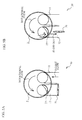
- FIGs. 3A and 3B are explanatory views of the air flow generated in the cylinder 2 in the above third intake period.
- FIG. 3A illustrates the cylinder 2 viewed from its upper side.
- FIG. 3B is a cross section taken along line A-A.
- the first intake passage 11 and the second intake passage 12 are illustrated, but the exhaust passage 6 is omitted.
- the second intake passage 12 and the exhaust passage 6 are illustrated.
- the first intake valve 13 opens in the first intake period in the cam characteristic of FIG. 2 , so that the flesh air is supplied only from the first intake passage 11 side to the cylinder 2. This generates the unbalanced flow in the cylinder 2, and the counterclockwise rotational flow occurs. This rotational flow promotes the mixture of the air and the fuel.
- the second intake valve 14 opens in the second intake period, so that the flesh air is also introduced from the second intake passage 12 side.
- the third intake period starts and the first intake valve 13 closes at the timing of starting the compression stroke.
- the second intake valve 14 is also in the opening state.
- the flow to this second intake passage 12 generates the counterclockwise rotational flow in the cylinder 2 as illustrated in FIGs. 3A and 3B .
- the rotational flow generated during this period has so low an attenuation as to maintain the turbulence of the air-fuel mixture until the combustion, because the compression period of the air-fuel mixture after the second intake valve 14 closes is short.
- the guide 27 provided in the second intake passage 12 obstructs the air which has flowed from the first intake passage 11 side toward the second intake passage 12 side.
- the guide 27 allows only the air, which has flowed from the outer circumstantial side within the cylinder 2 toward the second intake passage 12 side, to flow theretoward. This assists the rotational flow in flowing toward the second intake passage 12. Therefore, the rotational flow in the cylinder 2 is further strengthened, so the turbulence of the air-fuel mixture is maintained even after the second intake valve 14 closes. In such a way, the turbulence of the air-fuel mixture is maintained even after the second intake valve 14 closes, thereby making the air-fuel mixture uniform in the cylinder 2. This ensures the stable combustion.
- the VVT controller is capable of controlling the closing timing of the second intake valve 14 as mentioned above.
- the VVT controller sets the closing timing of the second intake valve 14 to be suitable for maintaining the rotational flow. Therefore, the engine 1 ensures the high torque and high output state.
- the intake apparatus 10 of the present embodiment there are the period while the first intake valve 13 opens and the second intake valve 14 closes during the intake stroke, and the period while the first intake valve 13 closes and the second intake valve 14 opens during the intake stroke. Therefore, in the period while the first intake valve 13 opens and the second intake valve 14 closes during the intake stroke, the rotational flow is generated along the inner circumferential wall of the cylinder 2. Further, in the period while the first intake valve 13 closes and the second intake valve 14 opens during the middle of the compression stroke, the rotational flow flows to the intake side. Since this rotational flow flows only toward the second passage of the intake side, the unbalance of the airflow occurs in the cylinder to suppress the rotational flow from attenuating.
- this flow causes the air to flow out of the cylinder 2, thereby making the expansion ratio higher than the compression ratio so as to reduce the pumping loss.
- the rotational flow is suppressed from attenuating with the pumping loss reduced, thereby promoting the mixture of the air and the fuel to form the stable combustion state. This enhances the EGR-resistant characteristic, thereby improving the fuel consumption.
- An intake apparatus 30 of the present embodiment is substantially the same as the intake apparatus 10 of the first embodiment.
- the intake apparatus 30 of the present embodiment differs from the intake apparatus 10 of the first embodiment in that an intake control valve 31 is provided for opening or closing the second intake passage 12 in the intake apparatus 30.
- This intake control valve 31 closes in the period in which the first intake valve 13 opens and the second intake valve 14 opens, whereas the intake control valve 31 opens in the period in which the first intake valve 13 closes and the second intake valve 14 opens.
- the other configurations of the intake apparatus 30 are the same as those of the intake apparatus 10 of the first embodiment, so the detailed descriptions of the same configuration elements as those of the intake apparatus 10 are omitted and the present embodiment will be described with the same reference numerals.
- FIG. 4 is an explanatory view of the opening and closing timings of the intake control valve 31.
- FIG. 4 is the explanatory view of the illustration of FIG. 2 , in the first embodiment, added with the opening and closing timings of the intake control valve 31.
- the intake control valve 31 and the second intake valve 14 close substantially at the same time.
- the intake control valve 31 opens at the timing when the first intake valve 13 closes.
- the intake control valve 31 has already opens before the first intake valve 13 closes.
- the intake control valve 31 opens in the period other than above one.
- FIGs. 5A and 5B are explanatory views of the air flow generated in the cylinder 2.
- FIG. 5A illustrates a state where the second intake valve 14 opens and the intake control valve 31 closes
- FIG. 5B illustrates a state where the intake control valve 31 opens with the second intake valve 14 opening.
- the intake control valve 31A closes at the same time as the second intake valve 14 opens, whereby the air flow is not generated in the second intake passage 12.
- the intake control valve 31 opens at the timing when the first intake valve 13 closes, and then the air flows from the cylinder 2 toward the second intake passage 12. This suppresses attenuation of the rotational flow, thereby increasing the turbulence of the airflow in the cylinder 2, as illustrated in FIG. 5B . Therefore, the turbulence of the airflow is maintained even after the second intake valve 14 closes, which spreads the air-fuel mixture to achieve the stable combustion. Additionally, the same effect is obtained even if the guide 27 is not provided in the present embodiment.
- FIG. 6 is an explanatory view illustrating a schematic configuration of the cylinder 2, the first intake passage 11, the second intake passage 12, and the exhaust passage 6 in an intake apparatus 40 of the present embodiment.
- the intake apparatus 40 of the present embodiment is substantially the same as the intake apparatus 1 of the first embodiment.
- the intake apparatus 40 of the present embodiment differs from the intake apparatus of the first embodiment in that the intake apparatus 40 is provided with a second injector 41 for the fuel injection in the second intake passage 12.
- the other configurations of the intake apparatus 40 are the same as those of the intake apparatus 10 of the first embodiment, so the detailed descriptions of the same configuration elements as the intake apparatus 10 are omitted and the present embodiment will be described with the same reference numerals.
- FIG. 7 is an explanatory view of injection timings of a first injector 26 and a second injector 41.
- FIG. 7 is the explanatory view of the illustration of FIG. 2 , in the first embodiment, added with the injection timing of the first injector 26 and the second injector 41.
- the first injector 26 performs the intake-asynchronous injection, and finishes the injection before the first intake valve 13 opens.
- the second injector 41 performs the intake-asynchronous injection, and injects the fuel at the time when the second intake valve 14 opens.
- the second injector 41 is provided, whereby the second injector 41 injects a part of the fuel, which is injected by the first injector 26 in case of providing the first injector only.
- the fuel injected by the second injector 41 faces the air flowing through the second intake passage 12, which atomizes the fuel spray. Therefore, the fuel vaporization is promoted to reduce the intake air temperature, thereby increasing the volumetric efficiency and improving the output. Additionally, the same effect is obtained without the guide 27 in the present embodiment.
- variable valve mechanism 17 may vary the working angle of the valve timing of the second intake valve 14.
- the second camshaft 16 is assembled with a variable valve mechanism such that a valve timing of the first intake valve 13 is variable. This flexibly controls the intake air in the cylinder 2, and improves the combustion efficiency.
Landscapes
- Engineering & Computer Science (AREA)
- Mechanical Engineering (AREA)
- General Engineering & Computer Science (AREA)
- Chemical & Material Sciences (AREA)
- Combustion & Propulsion (AREA)
- Output Control And Ontrol Of Special Type Engine (AREA)
- Combined Controls Of Internal Combustion Engines (AREA)
- Valve Device For Special Equipments (AREA)
Abstract

Description
- The present invention relates to an intake apparatus of an engine using a high expansion ratio cycle.
- Conventionally, an engine with a high expansion ratio cycle has been practically used, thereby increasing a high efficiency of the engine and making the expansion ratio higher than the compression ratio during the combustion cycle. According to
Patent Document 1, in the engine with the high expansion ratio cycle, the closing timing of an intake valve is retarded to make the expansion ratio higher than the compression ratio during the combustion cycle. This reduces the pump loss (pumping loss), which improves the heat efficiency and avoids knocking. - [Patent Document 1] Japanese Patent Application Publication No.
2004-183510 - Incidentally, in the compression stroke of the engine, the fuel-air mixture introduced to a cylinder is subject to the shearing stress by a change in a flow velocity, and then is compressed with turbulence generated. This turbulence uniformly spreads the fuel-air mixture in the cylinder, thereby ensuring the stable combustion. However, as for an engine with a high expansion ratio cycle by retarding the intake valve closing timing, that is, by a so-called intake valve retarded closing, the intake valve continues opening until the middle of the compression stroke. For this reason, the air-fuel mixture flows through the intake passage, so that the turbulence of the air-fuel mixture in the cylinder is dramatically attenuated. Specifically, at the time when the intake valve closes after passing the middle of the compression stroke, the turbulence of the air-fuel mixture in the cylinder is almost lost, which may arise a problem of the unstable combustion.
- It is therefore an object of the present invention to reduce pumping loss of an engine, achieve stable combustion, and improve fuel consumption.
- In order to solve the above problem, an intake apparatus of an engine according to the present invention includes: a first intake passage supplying fresh air to a cylinder; a second intake passage arranged near the first intake passage, and supplying fresh air to the cylinder; a first intake valve opening and closing The first intake passage at an aperture of the first intake passage; and a second intake valve opening and closing the second intake passage at an aperture of the second intake passage, wherein an opening timing of the first intake valve advances relative to a top dead center, and a valve lift amount of the first intake valve differs from that of the second intake valve, and there is a period during which the valve lift amount of the first intake valve is larger than that of the second intake valve, in an intake stroke.
- With such a configuration, the intake air flows out of the first intake passage with the first intake valve having a large lift amount toward the second intake passage with the second intake valve having a small lift amount. This outflow generates the rotational flow along an inner circumferential wall of the cylinder. Also, this causes the introduced fresh air to flow out, thereby making the expansion ratio larger than the compression ratio in the cylinder. Thus, this reduces the pumping loss. At this time, the fresh air flows through the second intake passage, so that an unbalance of the airflow occurs in the cylinder and then attenuation of the rotational flow is suppressed. In such a way, attenuation of the rotational flow generated in the cylinder is suppressed with the pumping loss being reduced. This promotes the mixture of the air and the fuel and forms the stable combustion state. Also, in the intake apparatus of the above engine, the valve lift amount of the first intake valve may be larger than that of the second intake valve in a first half of the intake stroke.
- In the above intake apparatus of the engine, the first intake valve may open before the second intake valve opens. Therefore, the fresh air flows through the first intake passage and then generates the rotational flow, while the first intake valve is opening and the second intake valve is closing. In the above intake apparatus of the engine, the first intake valve may close before the second intake valve closes. Therefore, the fresh air flows through the second intake passage so as to maintain the rotational flow, while the first intake valve is closing and the second intake valve is opening.
- The above intake apparatus of the engine may include an introduction portion introducing rotational flow generated in the cylinder toward the second passage. This configuration increases the airflow velocity flowing through the second passage. This improves the rotational flow velocity in the cylinder, thereby suppressing attenuation of the rotational flow.
- Further, the introduction portion may be a guide that is formed such that the rotational flow flows from a wall of the cylinder toward the second passage. This configuration suppresses the generation of the flow in such a direction as would attenuate the rotational flow of the gas flowing toward the second passage. This suppresses attenuation of the rotational flow, thereby promoting the mixture of the air and the fuel.
- The above intake apparatus of the engine may include a control valve opening and closing the second intake passage and arranged on the second intake passage, and the control valve may close in a period in which the first intake valve opens and the second intake valve opens, and the control valve may open in a period in which the first intake valve closes and the second intake valve opens. With this configuration, the air-fuel mixture is supplied only from the first intake passage to the cylinder in closing the control valve, thereby generating the unbalance of the airflow in the cylinder to generate the rotational flow. Also, the air flows only through the second intake passage at the time of opening an opening/closing valve, thereby further promoting the unbalance of the air flow to suppress the rotational flow from attenuating. Thus, the rotational flow maintains the turbulence of the air-fuel mixture in the cylinder, thereby ensuring the stable combustion.
- Further, the above intake apparatus of the engine may include a second passage injection valve injecting fuel to the second intake passage, and the second passage injection valve may inject the fuel when the second intake valve opens. With this configuration, the fuel is injected in the direction opposite to the direction in which the air flows from the cylinder to the second passage, thereby promoting the atomization of the fuel. This improves the combustion efficiency.
- Furthermore, the above intake apparatus of the engine may include: a first passage injection valve injecting fuel to the first intake passage; and a second passage injection valve injecting fuel to the second intake passage, the first passage injection valve may finish injection of the fuel before the first intake valve opens, and the second passage injection valve may inject the fuel when the second intake valve opens. This configuration reduces the air-fuel mixture to flow out at the time of the valve overlap. The first intake valve advances to open, whereby there is a period while the first intake valve overlaps an exhaust valve. The injection in the first intake passage is finished before the first intake valve opens in the present invention, thereby reducing the air-fuel mixture to flow out to the exhaust side. This improves the fuel consumption and the emission. Further, the fuel injected in the second passage side is atomized to improve the combustion efficiency.
- A control apparatus of an engine according to the present invention reduces the pumping loss, suppresses attenuation of the rotational flow generated in a cylinder, and promotes the mixture of air and fuel to form a stable combustion state.
-
-
FIGs. 1A and 1B are an explanatory views of an intake apparatus of a first embodiment,FIG. 1A is a front view of the intake apparatus, andFIG. 1B is a plane view of the intake apparatus; -
FIG. 2 is a view of characteristics of a first intake cam, a second intake cam, and an exhaust cam; -
FIGs. 3A and 3B are explanatory views of the air flow generated in a cylinder in a period while the first intake valve closes and the second intake valve opens,FIG. 3A illustrates the cylinder viewed from its upper side, andFIG. 3B is a cross section taken along line A-A; -
FIG. 4 is an explanatory view of opening and closing timings of an intake control valve; -
FIGs. 5A and 5B are explanatory views of the air flow generated in the cylinder in a second embodiment,FIG. 5A illustrates a state where the second intake valve opens and the intake control valve closes, andFIG. 5B illustrates a state where the intake control valve opens with the second intake valve opening; -
FIG. 6 is an explanatory view illustrating a schematic configuration of the cylinder, the first intake passage, the second intake passage, and the exhaust passage in an intake apparatus of a third embodiment; and -
FIG. 7 is an explanatory view of injection timings of a first and second injectors. - Embodiments will be described in detail with reference to drawings.
- A first embodiment will be described with reference to drawings.
FIGS. 1A and 1B are explanatory views of anintake apparatus 10 of the first embodiment.FIG. 1A is a front view of theintake apparatus 10, andFIG. 1B is a plane view of theintake apparatus 10. Theintake apparatus 10 supplies fresh air to acylinder 2 installed in anengine 1, and is provided for every cylinder. Theengine 1 in the present embodiment is a DOHC engine having four cylinders each having four valves. Here, asingle cylinder 2 of them will be described. - The
cylinder 2 is formed within acylinder head 3 and acylinder block 4. Apiston 5 is housed in thecylinder 2 and is capable of reciprocating motion. - The
intake apparatus 10 is provided with afirst intake passage 11 and asecond intake passage 12 as two intake passages supplying the fresh air to thecylinder 2. Thefirst intake passage 11 and thesecond intake passage 12 are formed in thecylinder head 3. Thefirst intake passage 11 and thesecond intake passage 12 are branched off from an intake manifold (not illustrated) and are arranged in parallel to be connected to thecylinder 2. Thefirst intake passage 11 is provided at its opening with afirst intake valve 13 for opening and closing thefirst intake passage 11. Also, thesecond intake passage 12 is provided at its opening with asecond intake valve 14 for opening and closing thesecond intake passage 12. - Further, the
intake apparatus 10 is provided with afirst injector 26 for injecting the fuel to thefirst intake passage 11. Furthermore, theintake apparatus 10 is provided with aguide 27 in thesecond intake passage 12. Thisguide 27 introduces the rotational flow generated in thecylinder 2 to thesecond intake passage 12. - Moreover, the
engine 1 is provided with anexhaust passage 6 that is branched off to two passages connected to thecylinder 2. The branchedexhaust passages 6 are provided at their openings withexhaust valves 7 for opening and closing theexhaust passages 6, respectively. - The
intake apparatus 1 is provided with afirst camshaft 15 and asecond camshaft 16. Avariable valve mechanism 17 is mounted to one end of thefirst camshaft 15. Thevariable valve mechanism 17 is formed at its outer circumference with a gear. Also, a drivensprocket 18 is mounted to one end of thesecond camshaft 16. The outer circumference of thevariable valve mechanism 17 and the drivensprocket 18 are connected to a drive sprocket (not illustrated) of a crank shaft side through atiming chain 19, and the rotation of the crank shaft is transmitted to thevariable valve mechanism 17 and the drivensprocket 18. This rotates thefirst camshaft 15 and thesecond camshaft 16. Thevariable valve mechanism 17 is provided with a vane type VVT (Variable Valve Timing) controller having hydraulic chambers. This VVT controller adjusts the hydraulic pressure such that the vanes rotate, which enables thefirst camshaft 15 to advance or retard. - A
second intake cam 20 is assembled into thefirst camshaft 15. Thesecond intake cam 20 presses down thesecond intake valve 14 through arocker arm 21 so as to open thesecond intake passage 12. On the other hand, twoexhaust cams 24 and afirst intake cam 22 are assembled into thesecond camshaft 16. Thefirst intake cam 22 presses down thefirst intake valve 13 through aroller rocker 23 so as to open thefirst intake passage 11. Also, theexhaust cam 24 presses down theexhaust valve 7 through thelocker arm 25 so as to open theexhaust passage 6. - Herein, a description will be given of characteristics of the
first intake cam 22, thesecond intake cam 20, and theexhaust cam 24.FIG. 2 is a view of characteristics of thefirst intake cam 22, thesecond intake cam 20, and theexhaust cam 24. InFIG. 2 , thepiston 5 is located in the top dead center at 0 degrees (=720 degrees) and 360 degrees. As illustrated inFIG. 2 , thefirst intake cam 22 is formed so as to start lifting the valve at an advancing side relative to the top dead center (360 degrees). Thus, the opening timing of thefirst intake valve 13 advances relative to the top dead center. On the other hand, the timing when thesecond intake cam 20 starts lifting the valve is controlled by the VVT controller. The timing when thesecond intake cam 20 starts lifting the valve can advance to be identically set to the opening timing of thefirst intake valve 13, and can be in retard relative to the top dead center. Additionally, inFIG. 2 , thesecond intake cam 20 starts lifting the valve at the retard side relative to the top dead center. Also, a working angle of thesecond intake cam 20 is formed to be higher than that of thefirst intake cam 22. That is, a period in which thesecond intake valve 14 opens is longer than a period in which thefirst intake valve 13 opens. Therefore, thesecond intake valve 14 closes later than thefirst intake valve 13 closes. Additionally, referring toFIG. 2 , thesecond intake valve 14 closes by about 90 degrees later than thefirst intake valve 13. That is, in the intake stroke of theintake apparatus 1, the valve lift amount of thefirst intake valve 13 differs from that of thesecond intake valve 14, and there is a period while the valve lift amount of thefirst intake valve 13 is larger than that of thesecond intake valve 14. In particular, in the first half of the intake stroke, the valve lift amount of thefirst intake valve 13 is larger than that of thesecond intake valve 14. The cam characteristics are set in such a way, so that there is a period while both of theexhaust valve 7 and thefirst intake valve 13 open, that is, an overlap period. Also, there are a period while thefirst intake valve 13 opens and thesecond intake valve 14 closes (hereinafter referred to as "a first intake period"), a period while both of thefirst intake valve 13 and thesecond intake valve 14 open (hereinafter referred to as "the second intake period"), and a period while thefirst intake valve 13 closes and thesecond intake valve 14 opens (hereinafter referred to as "the third intake period"). - Next, a description will be given of the air flow generated in the
cylinder 2 of theengine 1 in the intake stroke in this embodiment.FIGs. 3A and 3B are explanatory views of the air flow generated in thecylinder 2 in the above third intake period.FIG. 3A illustrates thecylinder 2 viewed from its upper side.FIG. 3B is a cross section taken along line A-A. InFIG. 3A , thefirst intake passage 11 and thesecond intake passage 12 are illustrated, but theexhaust passage 6 is omitted. InFIG. 3B , thesecond intake passage 12 and theexhaust passage 6 are illustrated. - When air intake starts, only the
first intake valve 13 opens in the first intake period in the cam characteristic ofFIG. 2 , so that the flesh air is supplied only from thefirst intake passage 11 side to thecylinder 2. This generates the unbalanced flow in thecylinder 2, and the counterclockwise rotational flow occurs. This rotational flow promotes the mixture of the air and the fuel. Next, thesecond intake valve 14 opens in the second intake period, so that the flesh air is also introduced from thesecond intake passage 12 side. - Moreover, the third intake period starts and the
first intake valve 13 closes at the timing of starting the compression stroke. Afterward, thesecond intake valve 14 is also in the opening state. Thus, the fresh air flows to thesecond intake passage 12 side. The flow to thissecond intake passage 12 generates the counterclockwise rotational flow in thecylinder 2 as illustrated inFIGs. 3A and 3B . The rotational flow generated during this period has so low an attenuation as to maintain the turbulence of the air-fuel mixture until the combustion, because the compression period of the air-fuel mixture after thesecond intake valve 14 closes is short. Further, theguide 27 provided in thesecond intake passage 12 obstructs the air which has flowed from thefirst intake passage 11 side toward thesecond intake passage 12 side. Theguide 27 allows only the air, which has flowed from the outer circumstantial side within thecylinder 2 toward thesecond intake passage 12 side, to flow theretoward. This assists the rotational flow in flowing toward thesecond intake passage 12. Therefore, the rotational flow in thecylinder 2 is further strengthened, so the turbulence of the air-fuel mixture is maintained even after thesecond intake valve 14 closes.
In such a way, the turbulence of the air-fuel mixture is maintained even after thesecond intake valve 14 closes, thereby making the air-fuel mixture uniform in thecylinder 2. This ensures the stable combustion. - Additionally, the VVT controller is capable of controlling the closing timing of the
second intake valve 14 as mentioned above. Thus, under the high speed and high load condition of theengine 1, the VVT controller sets the closing timing of thesecond intake valve 14 to be suitable for maintaining the rotational flow. Therefore, theengine 1 ensures the high torque and high output state. - As mentioned above, in the
intake apparatus 10 of the present embodiment, there are the period while thefirst intake valve 13 opens and thesecond intake valve 14 closes during the intake stroke, and the period while thefirst intake valve 13 closes and thesecond intake valve 14 opens during the intake stroke. Therefore, in the period while thefirst intake valve 13 opens and thesecond intake valve 14 closes during the intake stroke, the rotational flow is generated along the inner circumferential wall of thecylinder 2. Further, in the period while thefirst intake valve 13 closes and thesecond intake valve 14 opens during the middle of the compression stroke, the rotational flow flows to the intake side. Since this rotational flow flows only toward the second passage of the intake side, the unbalance of the airflow occurs in the cylinder to suppress the rotational flow from attenuating. Also, this flow causes the air to flow out of thecylinder 2, thereby making the expansion ratio higher than the compression ratio so as to reduce the pumping loss. In such a way, the rotational flow is suppressed from attenuating with the pumping loss reduced, thereby promoting the mixture of the air and the fuel to form the stable combustion state.
This enhances the EGR-resistant characteristic, thereby improving the fuel consumption. - Next, a second embodiment according to the present invention will be described. An
intake apparatus 30 of the present embodiment is substantially the same as theintake apparatus 10 of the first embodiment. However, theintake apparatus 30 of the present embodiment differs from theintake apparatus 10 of the first embodiment in that anintake control valve 31 is provided for opening or closing thesecond intake passage 12 in theintake apparatus 30. Thisintake control valve 31 closes in the period in which thefirst intake valve 13 opens and thesecond intake valve 14 opens, whereas theintake control valve 31 opens in the period in which thefirst intake valve 13 closes and thesecond intake valve 14 opens. Additionally, the other configurations of theintake apparatus 30 are the same as those of theintake apparatus 10 of the first embodiment, so the detailed descriptions of the same configuration elements as those of theintake apparatus 10 are omitted and the present embodiment will be described with the same reference numerals. -
FIG. 4 is an explanatory view of the opening and closing timings of theintake control valve 31.FIG. 4 is the explanatory view of the illustration ofFIG. 2 , in the first embodiment, added with the opening and closing timings of theintake control valve 31. Theintake control valve 31 and thesecond intake valve 14 close substantially at the same time. Theintake control valve 31 opens at the timing when thefirst intake valve 13 closes. Here, in consideration of a long period from the time when the valve opens or closes to the time when the air flow occurs, theintake control valve 31 has already opens before thefirst intake valve 13 closes. Also, theintake control valve 31 opens in the period other than above one. -
FIGs. 5A and 5B are explanatory views of the air flow generated in thecylinder 2.FIG. 5A illustrates a state where thesecond intake valve 14 opens and theintake control valve 31 closes, andFIG. 5B illustrates a state where theintake control valve 31 opens with thesecond intake valve 14 opening. - In the closing period of the
intake control valve 31 illustrated inFIG. 4 , the intake control valve 31A closes at the same time as thesecond intake valve 14 opens, whereby the air flow is not generated in thesecond intake passage 12.
Thus, in this period in which theintake control valve 31 closes, the air is supplied to thecylinder 2 only from thefirst intake passage 11, and the unbalance flow occurs in thecylinder 2, thereby promoting the generation of the rotational flow as illustrated inFIG. 5A . After that, theintake control valve 31 opens at the timing when thefirst intake valve 13 closes, and then the air flows from thecylinder 2 toward thesecond intake passage 12. This suppresses attenuation of the rotational flow, thereby increasing the turbulence of the airflow in thecylinder 2, as illustrated inFIG. 5B . Therefore, the turbulence of the airflow is maintained even after thesecond intake valve 14 closes, which spreads the air-fuel mixture to achieve the stable combustion. Additionally, the same effect is obtained even if theguide 27 is not provided in the present embodiment. - Next, a third embodiment according to the present invention is described.
FIG. 6 is an explanatory view illustrating a schematic configuration of thecylinder 2, thefirst intake passage 11, thesecond intake passage 12, and theexhaust passage 6 in anintake apparatus 40 of the present embodiment. Theintake apparatus 40 of the present embodiment is substantially the same as theintake apparatus 1 of the first embodiment. However, theintake apparatus 40 of the present embodiment differs from the intake apparatus of the first embodiment in that theintake apparatus 40 is provided with asecond injector 41 for the fuel injection in thesecond intake passage 12. Additionally, the other configurations of theintake apparatus 40 are the same as those of theintake apparatus 10 of the first embodiment, so the detailed descriptions of the same configuration elements as theintake apparatus 10 are omitted and the present embodiment will be described with the same reference numerals. -
FIG. 7 is an explanatory view of injection timings of afirst injector 26 and asecond injector 41.FIG. 7 is the explanatory view of the illustration ofFIG. 2 , in the first embodiment, added with the injection timing of thefirst injector 26 and thesecond injector 41. As illustrated inFIG. 7 , thefirst injector 26 performs the intake-asynchronous injection, and finishes the injection before thefirst intake valve 13 opens. On the other hand, thesecond injector 41 performs the intake-asynchronous injection, and injects the fuel at the time when thesecond intake valve 14 opens. - In the above manner, the
second injector 41 is provided, whereby thesecond injector 41 injects a part of the fuel, which is injected by thefirst injector 26 in case of providing the first injector only. This reduces the air-fuel mixture flowing through the exhaust side at the valve overlap time of thefirst intake valve 13 and theexhaust valve 7, thereby improving the fuel consumption and the emission. Also, in thesecond intake passage 12 side, the fuel injected by thesecond injector 41 faces the air flowing through thesecond intake passage 12, which atomizes the fuel spray. Therefore, the fuel vaporization is promoted to reduce the intake air temperature, thereby increasing the volumetric efficiency and improving the output. Additionally, the same effect is obtained without theguide 27 in the present embodiment. - While the exemplary embodiments of the present invention have been illustrated in detail, the present invention is not limited to the above-mentioned embodiments, and other embodiments, variations and modifications may be made without departing from the scope of the present invention.
- For example, in above examples, the
variable valve mechanism 17 may vary the working angle of the valve timing of thesecond intake valve 14. Also, thesecond camshaft 16 is assembled with a variable valve mechanism such that a valve timing of thefirst intake valve 13 is variable. This flexibly controls the intake air in thecylinder 2, and improves the combustion efficiency. -
- 1
- engine
- 2
- cylinder
- 6
- exhaust passage
- 7
- exhaust valve
- 10, 30, 40
- intake apparatus
- 11
- first intake passage
- 12
- second intake passage
- 13
- first intake valve
- 14
- second intake valve
- 15
- first camshaft
- 16
- second camshaft
- 17
- variable valve mechanism
- 18
- driven sprocket
- 19
- timing chain
- 20
- second intake cam
- 21
- rocker arm
- 22
- first intake cam
- 23
- roller rocker
- 26
- first injector
- 27
- guide
- 31
- intake control valve
- 41
- second injector
Claims (9)
- An intake apparatus of an engine comprising:a first intake passage for supplying fresh air to a cylinder;a second intake passage arranged near the first intake passage, and supplying fresh air to the cylinder;a first intake valve for opening and closing the first intake passage at an aperture of the first intake passage; anda second intake valve for opening and closing the second intake passage at an aperture of the second intake passage,wherein an opening timing of the first intake valve is advanced relative to a top dead center, anda valve lift amount of the first intake valve differs from that of the second intake valve, and there is a period during which the valve lift amount of the first intake valve is larger than that of the second intake valve, in an intake stroke.
- The intake apparatus of the engine of claim 1, characterized in that the valve lift amount of the first intake valve is larger than that of the second intake valve in a first half of the intake stroke.
- The intake apparatus of the engine of claim 1 or 2, characterized in that the first intake valve opens before the second intake valve opens.
- The intake apparatus of the engine of any one of claims 1 to 3, characterized in that the first intake valve closes before the second intake valve closes.
- The intake apparatus of the engine of any one of claims 1 to 4, further comprising an introduction portion for introducing rotational flow generated in the cylinder toward the second passage.
- The intake apparatus of the engine of claim 5, characterized in that the introduction portion is a guide that is formed such that the rotational flow flows from a wall of the cylinder toward the second passage.
- The intake apparatus of the engine of any one of claims 1 to 6, further comprising a control valve for opening and closing the second intake passage and arranged on the second intake passage,
characterized in that the control valve closes in a period in which the first intake valve opens and the second intake valve opens, and the control valve opens in a period in which the first intake valve closes and the second intake valve opens. - The intake apparatus of the engine of any one of claims 1 to 7, further comprising a second passage injection valve for injecting fuel to the second intake passage,
characterized in that the second passage injection valve injects the fuel when the second intake valve opens. - The intake apparatus of the engine of any one of claims 1 to 7, further comprising:a first passage injection valve injecting fuel to the first intake passage; anda second passage injection valve injecting fuel to the second intake passage,characterized in that the first passage injection valve finishes injection of the fuel before the first intake valve opens, and the second passage injection valve injects the fuel when the second intake valve opens.
Applications Claiming Priority (2)
| Application Number | Priority Date | Filing Date | Title |
|---|---|---|---|
| JP2009253992 | 2009-11-05 | ||
| PCT/JP2010/068319 WO2011055629A1 (en) | 2009-11-05 | 2010-10-19 | Intake apparatus of engine |
Publications (3)
| Publication Number | Publication Date |
|---|---|
| EP2497925A1 true EP2497925A1 (en) | 2012-09-12 |
| EP2497925A4 EP2497925A4 (en) | 2013-12-04 |
| EP2497925B1 EP2497925B1 (en) | 2014-12-17 |
Family
ID=43969869
Family Applications (1)
| Application Number | Title | Priority Date | Filing Date |
|---|---|---|---|
| EP10828189.0A Not-in-force EP2497925B1 (en) | 2009-11-05 | 2010-10-19 | Intake apparatus of engine |
Country Status (5)
| Country | Link |
|---|---|
| US (1) | US9086021B2 (en) |
| EP (1) | EP2497925B1 (en) |
| JP (1) | JP5218671B2 (en) |
| CN (1) | CN102762841B (en) |
| WO (1) | WO2011055629A1 (en) |
Cited By (1)
| Publication number | Priority date | Publication date | Assignee | Title |
|---|---|---|---|---|
| EP3002440A1 (en) * | 2014-10-03 | 2016-04-06 | Mitsubishi Jidosha Kogyo K.K. | Internal combustion engine |
Families Citing this family (12)
| Publication number | Priority date | Publication date | Assignee | Title |
|---|---|---|---|---|
| JP5673397B2 (en) * | 2011-07-04 | 2015-02-18 | 三菱自動車工業株式会社 | Engine control device |
| JP5502033B2 (en) * | 2011-07-21 | 2014-05-28 | 日立オートモティブシステムズ株式会社 | Control device for internal combustion engine |
| WO2013098905A1 (en) * | 2011-12-25 | 2013-07-04 | Yaoita Yasuhito | Spark ignition four-stroke engine |
| US20140156174A1 (en) * | 2012-12-05 | 2014-06-05 | Hyundai Motor Company | Fuel distributor for dual-injector engine and method of controlling fuel distributor |
| KR101393571B1 (en) * | 2012-12-17 | 2014-05-12 | 기아자동차 주식회사 | Engine having variable valve timint device and variable tumble device |
| CN103437897B (en) * | 2013-08-19 | 2015-11-18 | 重庆长安汽车股份有限公司 | A kind of Atkinson cycle engine combustion system |
| JP6236739B2 (en) * | 2013-10-25 | 2017-11-29 | スズキ株式会社 | Internal combustion engine |
| JP2015175249A (en) * | 2014-03-13 | 2015-10-05 | 本田技研工業株式会社 | Internal combustion engine combustion controller |
| US10668414B2 (en) | 2014-07-23 | 2020-06-02 | Cummins Filtration Ip, Inc. | Intake bypass flow management systems and methods |
| US20180112633A1 (en) * | 2016-10-20 | 2018-04-26 | GM Global Technology Operations LLC | Method for operating an internal combustion engine employing a dedicated-cylinder egr system |
| US10539080B2 (en) | 2017-04-21 | 2020-01-21 | Peter Chargo | Internal combustion engine injection system |
| CN106939808B (en) * | 2017-04-26 | 2023-06-02 | 哈尔滨工程大学 | Exhaust valve device with hydraulic rotary valve device applied to low-speed diesel engine |
Citations (8)
| Publication number | Priority date | Publication date | Assignee | Title |
|---|---|---|---|---|
| US4570590A (en) * | 1984-07-10 | 1986-02-18 | Toyota Jidosha Kabushiki Kaisha | Internal combustion engine with multiple intake valves |
| JPS61218726A (en) * | 1985-03-26 | 1986-09-29 | Nissan Motor Co Ltd | Intake device of internal-combustion engine |
| US4703734A (en) * | 1985-03-06 | 1987-11-03 | Nissan Motor Co., Ltd. | Multi-valve internal combustion engine |
| JPH05133212A (en) * | 1992-05-18 | 1993-05-28 | Nissan Motor Co Ltd | Multiple cylinder internal combustion engine |
| WO2004074659A1 (en) * | 2003-02-20 | 2004-09-02 | Daimlerchrysler Ag | Method for controlling an inlet valve of an internal combustion engine |
| EP1469175A2 (en) * | 2003-04-18 | 2004-10-20 | Nissan Motor Co., Ltd. | Intake system of internal combustion engine |
| JP2009228640A (en) * | 2008-03-25 | 2009-10-08 | Honda Motor Co Ltd | Valve train for engine |
| US20100212618A1 (en) * | 2009-02-23 | 2010-08-26 | Shinichi Murata | Internal combustion engine with variable valve gear |
Family Cites Families (32)
| Publication number | Priority date | Publication date | Assignee | Title |
|---|---|---|---|---|
| US4191140A (en) * | 1978-03-06 | 1980-03-04 | Yamaha Hatsudoki Kabushiki Kaisha | Induction flow guide device for internal combustion engine intake manifold |
| US4354463A (en) * | 1979-06-09 | 1982-10-19 | Honda Giken Kogyo Kabushiki Kaisha | Device for improving combustion efficiency of mixture in four cycle internal combustion engine |
| US4856473A (en) * | 1987-08-25 | 1989-08-15 | Toyota Jidosha Kabushiki Kaisha | Internal combustion engine with multiple intake valves and EGR arrangement |
| JPH08260925A (en) | 1995-03-24 | 1996-10-08 | Nissan Motor Co Ltd | Intake system of engine |
| JPH1026026A (en) | 1996-07-09 | 1998-01-27 | Hitachi Ltd | Spark ignition engine |
| US6138651A (en) * | 1997-05-30 | 2000-10-31 | Nissan Motor Co., Ltd. | Exhaust gas recirculation system for engine |
| JP3256671B2 (en) * | 1997-08-01 | 2002-02-12 | 本田技研工業株式会社 | Internal combustion engine piston |
| JP3807174B2 (en) * | 1999-12-06 | 2006-08-09 | 日産自動車株式会社 | Engine control device |
| JP3799944B2 (en) * | 2000-03-21 | 2006-07-19 | トヨタ自動車株式会社 | Variable valve mechanism and intake air amount control device for internal combustion engine |
| US6397813B1 (en) * | 2000-04-28 | 2002-06-04 | Ford Global Technologies, Inc. | Method and apparatus for inducing swirl in an engine cylinder by controlling engine valves |
| JP2002206446A (en) * | 2001-01-10 | 2002-07-26 | Hitachi Ltd | Internal combustion engine and fuel injection control device for the internal combustion engine |
| JP2002242716A (en) * | 2001-02-21 | 2002-08-28 | Hitachi Ltd | Control device for cylinder injection engine |
| US20030127063A1 (en) * | 2002-01-10 | 2003-07-10 | Yushu Wang | Continually variable valve timing, lift, and duration for internal combustion engine |
| DE10228022B4 (en) * | 2002-06-20 | 2009-04-23 | Entec Consulting Gmbh | Valve lifting device for stroke adjustment of the gas exchange valves of an internal combustion engine |
| JP4045915B2 (en) * | 2002-10-03 | 2008-02-13 | 日産自動車株式会社 | Intake device for internal combustion engine |
| JP3861789B2 (en) * | 2002-10-03 | 2006-12-20 | 日産自動車株式会社 | Intake device for internal combustion engine |
| JP4151395B2 (en) | 2002-11-29 | 2008-09-17 | 三菱自動車工業株式会社 | High expansion ratio cycle engine |
| EP1457651A2 (en) * | 2003-03-10 | 2004-09-15 | Hitachi, Ltd. | Mixture supply device for internal-combustion engine |
| JP3903942B2 (en) * | 2003-04-03 | 2007-04-11 | 日産自動車株式会社 | Intake device for internal combustion engine |
| JP4137731B2 (en) * | 2003-07-28 | 2008-08-20 | 本田技研工業株式会社 | Valve control device for internal combustion engine |
| JP2006161666A (en) | 2004-12-07 | 2006-06-22 | Mazda Motor Corp | Intake exhaust control device for engine |
| CN100580238C (en) * | 2005-01-31 | 2010-01-13 | 丰田自动车株式会社 | Control apparatus for internal combustion engine |
| JP4100401B2 (en) * | 2005-02-24 | 2008-06-11 | トヨタ自動車株式会社 | Internal combustion engine |
| JP2006283696A (en) * | 2005-04-01 | 2006-10-19 | Toyota Motor Corp | Intake device of internal combustion engine |
| US7377236B2 (en) * | 2005-09-09 | 2008-05-27 | Ford Global Technologies, Llc | System and method for exhaust heat generation using electrically actuated cylinder valves and variable stroke combustion cycles |
| US7992541B2 (en) * | 2006-03-14 | 2011-08-09 | Ford Global Technologies, Llc | System and method for controlling auto-ignition |
| JP4680828B2 (en) * | 2006-05-11 | 2011-05-11 | 本田技研工業株式会社 | Engine intake port structure |
| JP2008095600A (en) * | 2006-10-12 | 2008-04-24 | Hitachi Ltd | Valve gear for multiple cylinder internal combustion engine, and assembling method thereof |
| JP2008202406A (en) * | 2007-02-16 | 2008-09-04 | Toyota Motor Corp | Intake valve controller of internal combustion engine and internal combustion engine having same |
| JP2009074401A (en) * | 2007-09-19 | 2009-04-09 | Aisan Ind Co Ltd | Intake manifold |
| US7992537B2 (en) * | 2007-10-04 | 2011-08-09 | Ford Global Technologies, Llc | Approach for improved fuel vaporization in a directly injected internal combustion engine |
| JP2009103108A (en) * | 2007-10-25 | 2009-05-14 | Toyota Motor Corp | Cylinder direct injection type internal combustion engine |
-
2010
- 2010-10-19 US US13/499,477 patent/US9086021B2/en not_active Expired - Fee Related
- 2010-10-19 WO PCT/JP2010/068319 patent/WO2011055629A1/en active Application Filing
- 2010-10-19 CN CN201080049925.5A patent/CN102762841B/en not_active Expired - Fee Related
- 2010-10-19 EP EP10828189.0A patent/EP2497925B1/en not_active Not-in-force
- 2010-10-19 JP JP2011539330A patent/JP5218671B2/en active Active
Patent Citations (8)
| Publication number | Priority date | Publication date | Assignee | Title |
|---|---|---|---|---|
| US4570590A (en) * | 1984-07-10 | 1986-02-18 | Toyota Jidosha Kabushiki Kaisha | Internal combustion engine with multiple intake valves |
| US4703734A (en) * | 1985-03-06 | 1987-11-03 | Nissan Motor Co., Ltd. | Multi-valve internal combustion engine |
| JPS61218726A (en) * | 1985-03-26 | 1986-09-29 | Nissan Motor Co Ltd | Intake device of internal-combustion engine |
| JPH05133212A (en) * | 1992-05-18 | 1993-05-28 | Nissan Motor Co Ltd | Multiple cylinder internal combustion engine |
| WO2004074659A1 (en) * | 2003-02-20 | 2004-09-02 | Daimlerchrysler Ag | Method for controlling an inlet valve of an internal combustion engine |
| EP1469175A2 (en) * | 2003-04-18 | 2004-10-20 | Nissan Motor Co., Ltd. | Intake system of internal combustion engine |
| JP2009228640A (en) * | 2008-03-25 | 2009-10-08 | Honda Motor Co Ltd | Valve train for engine |
| US20100212618A1 (en) * | 2009-02-23 | 2010-08-26 | Shinichi Murata | Internal combustion engine with variable valve gear |
Non-Patent Citations (1)
| Title |
|---|
| See also references of WO2011055629A1 * |
Cited By (1)
| Publication number | Priority date | Publication date | Assignee | Title |
|---|---|---|---|---|
| EP3002440A1 (en) * | 2014-10-03 | 2016-04-06 | Mitsubishi Jidosha Kogyo K.K. | Internal combustion engine |
Also Published As
| Publication number | Publication date |
|---|---|
| EP2497925A4 (en) | 2013-12-04 |
| EP2497925B1 (en) | 2014-12-17 |
| CN102762841B (en) | 2016-03-30 |
| JP5218671B2 (en) | 2013-06-26 |
| CN102762841A (en) | 2012-10-31 |
| US20120210979A1 (en) | 2012-08-23 |
| US9086021B2 (en) | 2015-07-21 |
| WO2011055629A1 (en) | 2011-05-12 |
| JPWO2011055629A1 (en) | 2013-03-28 |
Similar Documents
| Publication | Publication Date | Title |
|---|---|---|
| EP2497925B1 (en) | Intake apparatus of engine | |
| US8171901B2 (en) | Internal combustion engine with variable valve gear | |
| KR101421318B1 (en) | Internal combustion engine with variable valve gear | |
| US9470174B2 (en) | Control system and control method of spark ignition gasoline engine | |
| EP2948667B1 (en) | Method for operating piston engine and piston engine | |
| US8695544B2 (en) | High expansion ratio internal combustion engine | |
| EP1234965A2 (en) | Control system for direct fuel injection engine | |
| KR20190003990A (en) | Method for operating internal combustion engine and internal combustion engine | |
| JP4918910B2 (en) | Internal combustion engine | |
| JP2008274963A (en) | Spark ignition internal combustion engine | |
| US8397693B2 (en) | Engine including system and method for reducing oil pull-over in combustion chamber | |
| JP6241678B2 (en) | Engine control device | |
| RU2633336C2 (en) | Internal combustion engine with forced ignition and method of internal combustion engine with forced ignition control | |
| JPH0531659B2 (en) | ||
| JPH11229913A (en) | Valve system of internal combustion engine | |
| JP2018168719A (en) | Internal combustion engine | |
| US8991357B2 (en) | Internal combustion engine | |
| JP2004316449A (en) | Direct injection spark ignition type internal combustion engine | |
| JP3372670B2 (en) | Engine intake system | |
| JP2012117405A (en) | Internal combustion engine | |
| KR100643823B1 (en) | A crosshead Diesel engine having cylinders with combustion chambers, and a method of injecting fuel in such engine | |
| JP2016125449A (en) | Variable miller cycle engine control method and control device | |
| KR100515254B1 (en) | Internal injection engine | |
| JP5516896B2 (en) | Internal combustion engine with variable valve gear | |
| JP2014173493A (en) | Compression ignition engine |
Legal Events
| Date | Code | Title | Description |
|---|---|---|---|
| PUAI | Public reference made under article 153(3) epc to a published international application that has entered the european phase |
Free format text: ORIGINAL CODE: 0009012 |
|
| 17P | Request for examination filed |
Effective date: 20120504 |
|
| AK | Designated contracting states |
Kind code of ref document: A1 Designated state(s): AL AT BE BG CH CY CZ DE DK EE ES FI FR GB GR HR HU IE IS IT LI LT LU LV MC MK MT NL NO PL PT RO RS SE SI SK SM TR |
|
| DAX | Request for extension of the european patent (deleted) | ||
| RAP1 | Party data changed (applicant data changed or rights of an application transferred) |
Owner name: TOYOTA JIDOSHA KABUSHIKI KAISHA |
|
| A4 | Supplementary search report drawn up and despatched |
Effective date: 20131105 |
|
| RIC1 | Information provided on ipc code assigned before grant |
Ipc: F01L 1/34 20060101ALI20131029BHEP Ipc: F02D 41/34 20060101ALI20131029BHEP Ipc: F02D 13/02 20060101AFI20131029BHEP Ipc: F02M 69/00 20060101ALI20131029BHEP Ipc: F02B 31/02 20060101ALI20131029BHEP |
|
| GRAP | Despatch of communication of intention to grant a patent |
Free format text: ORIGINAL CODE: EPIDOSNIGR1 |
|
| INTG | Intention to grant announced |
Effective date: 20140708 |
|
| GRAS | Grant fee paid |
Free format text: ORIGINAL CODE: EPIDOSNIGR3 |
|
| GRAA | (expected) grant |
Free format text: ORIGINAL CODE: 0009210 |
|
| AK | Designated contracting states |
Kind code of ref document: B1 Designated state(s): AL AT BE BG CH CY CZ DE DK EE ES FI FR GB GR HR HU IE IS IT LI LT LU LV MC MK MT NL NO PL PT RO RS SE SI SK SM TR |
|
| REG | Reference to a national code |
Ref country code: GB Ref legal event code: FG4D |
|
| REG | Reference to a national code |
Ref country code: CH Ref legal event code: EP |
|
| REG | Reference to a national code |
Ref country code: IE Ref legal event code: FG4D |
|
| REG | Reference to a national code |
Ref country code: AT Ref legal event code: REF Ref document number: 702119 Country of ref document: AT Kind code of ref document: T Effective date: 20150115 |
|
| REG | Reference to a national code |
Ref country code: DE Ref legal event code: R096 Ref document number: 602010021183 Country of ref document: DE Effective date: 20150205 |
|
| PG25 | Lapsed in a contracting state [announced via postgrant information from national office to epo] |
Ref country code: LT Free format text: LAPSE BECAUSE OF FAILURE TO SUBMIT A TRANSLATION OF THE DESCRIPTION OR TO PAY THE FEE WITHIN THE PRESCRIBED TIME-LIMIT Effective date: 20141217 Ref country code: NO Free format text: LAPSE BECAUSE OF FAILURE TO SUBMIT A TRANSLATION OF THE DESCRIPTION OR TO PAY THE FEE WITHIN THE PRESCRIBED TIME-LIMIT Effective date: 20150317 Ref country code: FI Free format text: LAPSE BECAUSE OF FAILURE TO SUBMIT A TRANSLATION OF THE DESCRIPTION OR TO PAY THE FEE WITHIN THE PRESCRIBED TIME-LIMIT Effective date: 20141217 |
|
| REG | Reference to a national code |
Ref country code: LT Ref legal event code: MG4D |
|
| PG25 | Lapsed in a contracting state [announced via postgrant information from national office to epo] |
Ref country code: RS Free format text: LAPSE BECAUSE OF FAILURE TO SUBMIT A TRANSLATION OF THE DESCRIPTION OR TO PAY THE FEE WITHIN THE PRESCRIBED TIME-LIMIT Effective date: 20141217 Ref country code: HR Free format text: LAPSE BECAUSE OF FAILURE TO SUBMIT A TRANSLATION OF THE DESCRIPTION OR TO PAY THE FEE WITHIN THE PRESCRIBED TIME-LIMIT Effective date: 20141217 Ref country code: GR Free format text: LAPSE BECAUSE OF FAILURE TO SUBMIT A TRANSLATION OF THE DESCRIPTION OR TO PAY THE FEE WITHIN THE PRESCRIBED TIME-LIMIT Effective date: 20150318 Ref country code: SE Free format text: LAPSE BECAUSE OF FAILURE TO SUBMIT A TRANSLATION OF THE DESCRIPTION OR TO PAY THE FEE WITHIN THE PRESCRIBED TIME-LIMIT Effective date: 20141217 Ref country code: LV Free format text: LAPSE BECAUSE OF FAILURE TO SUBMIT A TRANSLATION OF THE DESCRIPTION OR TO PAY THE FEE WITHIN THE PRESCRIBED TIME-LIMIT Effective date: 20141217 |
|
| REG | Reference to a national code |
Ref country code: AT Ref legal event code: MK05 Ref document number: 702119 Country of ref document: AT Kind code of ref document: T Effective date: 20141217 |
|
| PG25 | Lapsed in a contracting state [announced via postgrant information from national office to epo] |
Ref country code: NL Free format text: LAPSE BECAUSE OF FAILURE TO SUBMIT A TRANSLATION OF THE DESCRIPTION OR TO PAY THE FEE WITHIN THE PRESCRIBED TIME-LIMIT Effective date: 20141217 |
|
| REG | Reference to a national code |
Ref country code: DE Ref legal event code: R084 Ref document number: 602010021183 Country of ref document: DE |
|
| PG25 | Lapsed in a contracting state [announced via postgrant information from national office to epo] |
Ref country code: CZ Free format text: LAPSE BECAUSE OF FAILURE TO SUBMIT A TRANSLATION OF THE DESCRIPTION OR TO PAY THE FEE WITHIN THE PRESCRIBED TIME-LIMIT Effective date: 20141217 Ref country code: ES Free format text: LAPSE BECAUSE OF FAILURE TO SUBMIT A TRANSLATION OF THE DESCRIPTION OR TO PAY THE FEE WITHIN THE PRESCRIBED TIME-LIMIT Effective date: 20141217 Ref country code: SK Free format text: LAPSE BECAUSE OF FAILURE TO SUBMIT A TRANSLATION OF THE DESCRIPTION OR TO PAY THE FEE WITHIN THE PRESCRIBED TIME-LIMIT Effective date: 20141217 Ref country code: RO Free format text: LAPSE BECAUSE OF FAILURE TO SUBMIT A TRANSLATION OF THE DESCRIPTION OR TO PAY THE FEE WITHIN THE PRESCRIBED TIME-LIMIT Effective date: 20141217 Ref country code: EE Free format text: LAPSE BECAUSE OF FAILURE TO SUBMIT A TRANSLATION OF THE DESCRIPTION OR TO PAY THE FEE WITHIN THE PRESCRIBED TIME-LIMIT Effective date: 20141217 |
|
| PG25 | Lapsed in a contracting state [announced via postgrant information from national office to epo] |
Ref country code: PL Free format text: LAPSE BECAUSE OF FAILURE TO SUBMIT A TRANSLATION OF THE DESCRIPTION OR TO PAY THE FEE WITHIN THE PRESCRIBED TIME-LIMIT Effective date: 20141217 Ref country code: AT Free format text: LAPSE BECAUSE OF FAILURE TO SUBMIT A TRANSLATION OF THE DESCRIPTION OR TO PAY THE FEE WITHIN THE PRESCRIBED TIME-LIMIT Effective date: 20141217 Ref country code: IS Free format text: LAPSE BECAUSE OF FAILURE TO SUBMIT A TRANSLATION OF THE DESCRIPTION OR TO PAY THE FEE WITHIN THE PRESCRIBED TIME-LIMIT Effective date: 20150417 |
|
| REG | Reference to a national code |
Ref country code: DE Ref legal event code: R097 Ref document number: 602010021183 Country of ref document: DE |
|
| PLBE | No opposition filed within time limit |
Free format text: ORIGINAL CODE: 0009261 |
|
| STAA | Information on the status of an ep patent application or granted ep patent |
Free format text: STATUS: NO OPPOSITION FILED WITHIN TIME LIMIT |
|
| PG25 | Lapsed in a contracting state [announced via postgrant information from national office to epo] |
Ref country code: DK Free format text: LAPSE BECAUSE OF FAILURE TO SUBMIT A TRANSLATION OF THE DESCRIPTION OR TO PAY THE FEE WITHIN THE PRESCRIBED TIME-LIMIT Effective date: 20141217 |
|
| 26N | No opposition filed |
Effective date: 20150918 |
|
| PG25 | Lapsed in a contracting state [announced via postgrant information from national office to epo] |
Ref country code: IT Free format text: LAPSE BECAUSE OF FAILURE TO SUBMIT A TRANSLATION OF THE DESCRIPTION OR TO PAY THE FEE WITHIN THE PRESCRIBED TIME-LIMIT Effective date: 20141217 |
|
| PG25 | Lapsed in a contracting state [announced via postgrant information from national office to epo] |
Ref country code: SI Free format text: LAPSE BECAUSE OF FAILURE TO SUBMIT A TRANSLATION OF THE DESCRIPTION OR TO PAY THE FEE WITHIN THE PRESCRIBED TIME-LIMIT Effective date: 20141217 |
|
| PG25 | Lapsed in a contracting state [announced via postgrant information from national office to epo] |
Ref country code: BE Free format text: LAPSE BECAUSE OF FAILURE TO SUBMIT A TRANSLATION OF THE DESCRIPTION OR TO PAY THE FEE WITHIN THE PRESCRIBED TIME-LIMIT Effective date: 20141217 Ref country code: LU Free format text: LAPSE BECAUSE OF FAILURE TO SUBMIT A TRANSLATION OF THE DESCRIPTION OR TO PAY THE FEE WITHIN THE PRESCRIBED TIME-LIMIT Effective date: 20151019 |
|
| REG | Reference to a national code |
Ref country code: CH Ref legal event code: PL |
|
| GBPC | Gb: european patent ceased through non-payment of renewal fee |
Effective date: 20151019 |
|
| PG25 | Lapsed in a contracting state [announced via postgrant information from national office to epo] |
Ref country code: MC Free format text: LAPSE BECAUSE OF FAILURE TO SUBMIT A TRANSLATION OF THE DESCRIPTION OR TO PAY THE FEE WITHIN THE PRESCRIBED TIME-LIMIT Effective date: 20141217 |
|
| REG | Reference to a national code |
Ref country code: IE Ref legal event code: MM4A |
|
| PG25 | Lapsed in a contracting state [announced via postgrant information from national office to epo] |
Ref country code: LI Free format text: LAPSE BECAUSE OF NON-PAYMENT OF DUE FEES Effective date: 20151031 Ref country code: GB Free format text: LAPSE BECAUSE OF NON-PAYMENT OF DUE FEES Effective date: 20151019 Ref country code: CH Free format text: LAPSE BECAUSE OF NON-PAYMENT OF DUE FEES Effective date: 20151031 |
|
| REG | Reference to a national code |
Ref country code: FR Ref legal event code: ST Effective date: 20160630 |
|
| PG25 | Lapsed in a contracting state [announced via postgrant information from national office to epo] |
Ref country code: FR Free format text: LAPSE BECAUSE OF NON-PAYMENT OF DUE FEES Effective date: 20151102 |
|
| PG25 | Lapsed in a contracting state [announced via postgrant information from national office to epo] |
Ref country code: IE Free format text: LAPSE BECAUSE OF NON-PAYMENT OF DUE FEES Effective date: 20151019 |
|
| PG25 | Lapsed in a contracting state [announced via postgrant information from national office to epo] |
Ref country code: SM Free format text: LAPSE BECAUSE OF FAILURE TO SUBMIT A TRANSLATION OF THE DESCRIPTION OR TO PAY THE FEE WITHIN THE PRESCRIBED TIME-LIMIT Effective date: 20141217 Ref country code: HU Free format text: LAPSE BECAUSE OF FAILURE TO SUBMIT A TRANSLATION OF THE DESCRIPTION OR TO PAY THE FEE WITHIN THE PRESCRIBED TIME-LIMIT; INVALID AB INITIO Effective date: 20101019 Ref country code: BG Free format text: LAPSE BECAUSE OF FAILURE TO SUBMIT A TRANSLATION OF THE DESCRIPTION OR TO PAY THE FEE WITHIN THE PRESCRIBED TIME-LIMIT Effective date: 20141217 |
|
| PG25 | Lapsed in a contracting state [announced via postgrant information from national office to epo] |
Ref country code: CY Free format text: LAPSE BECAUSE OF FAILURE TO SUBMIT A TRANSLATION OF THE DESCRIPTION OR TO PAY THE FEE WITHIN THE PRESCRIBED TIME-LIMIT Effective date: 20141217 |
|
| PG25 | Lapsed in a contracting state [announced via postgrant information from national office to epo] |
Ref country code: MT Free format text: LAPSE BECAUSE OF FAILURE TO SUBMIT A TRANSLATION OF THE DESCRIPTION OR TO PAY THE FEE WITHIN THE PRESCRIBED TIME-LIMIT Effective date: 20141217 Ref country code: TR Free format text: LAPSE BECAUSE OF FAILURE TO SUBMIT A TRANSLATION OF THE DESCRIPTION OR TO PAY THE FEE WITHIN THE PRESCRIBED TIME-LIMIT Effective date: 20141217 |
|
| PG25 | Lapsed in a contracting state [announced via postgrant information from national office to epo] |
Ref country code: MK Free format text: LAPSE BECAUSE OF FAILURE TO SUBMIT A TRANSLATION OF THE DESCRIPTION OR TO PAY THE FEE WITHIN THE PRESCRIBED TIME-LIMIT Effective date: 20141217 |
|
| PG25 | Lapsed in a contracting state [announced via postgrant information from national office to epo] |
Ref country code: PT Free format text: LAPSE BECAUSE OF FAILURE TO SUBMIT A TRANSLATION OF THE DESCRIPTION OR TO PAY THE FEE WITHIN THE PRESCRIBED TIME-LIMIT Effective date: 20141217 |
|
| PG25 | Lapsed in a contracting state [announced via postgrant information from national office to epo] |
Ref country code: AL Free format text: LAPSE BECAUSE OF FAILURE TO SUBMIT A TRANSLATION OF THE DESCRIPTION OR TO PAY THE FEE WITHIN THE PRESCRIBED TIME-LIMIT Effective date: 20141217 |
|
| PGFP | Annual fee paid to national office [announced via postgrant information from national office to epo] |
Ref country code: DE Payment date: 20210908 Year of fee payment: 12 |
|
| REG | Reference to a national code |
Ref country code: DE Ref legal event code: R119 Ref document number: 602010021183 Country of ref document: DE |
|
| PG25 | Lapsed in a contracting state [announced via postgrant information from national office to epo] |
Ref country code: DE Free format text: LAPSE BECAUSE OF NON-PAYMENT OF DUE FEES Effective date: 20230503 |