EP2497678A2 - Procédés et systèmes de chargement d'un véhicule électrique - Google Patents
Procédés et systèmes de chargement d'un véhicule électrique Download PDFInfo
- Publication number
- EP2497678A2 EP2497678A2 EP20120158055 EP12158055A EP2497678A2 EP 2497678 A2 EP2497678 A2 EP 2497678A2 EP 20120158055 EP20120158055 EP 20120158055 EP 12158055 A EP12158055 A EP 12158055A EP 2497678 A2 EP2497678 A2 EP 2497678A2
- Authority
- EP
- European Patent Office
- Prior art keywords
- distribution transformer
- electric vehicle
- vehicle charging
- charging apparatus
- processing device
- Prior art date
- Legal status (The legal status is an assumption and is not a legal conclusion. Google has not performed a legal analysis and makes no representation as to the accuracy of the status listed.)
- Granted
Links
- 238000000034 method Methods 0.000 title claims description 39
- 238000012545 processing Methods 0.000 claims abstract description 73
- 238000004891 communication Methods 0.000 claims description 7
- 239000004020 conductor Substances 0.000 description 16
- 230000005611 electricity Effects 0.000 description 5
- 230000006870 function Effects 0.000 description 5
- 238000010586 diagram Methods 0.000 description 4
- 230000015654 memory Effects 0.000 description 3
- 230000003068 static effect Effects 0.000 description 3
- 230000007423 decrease Effects 0.000 description 2
- 238000005259 measurement Methods 0.000 description 2
- 230000004044 response Effects 0.000 description 2
- 238000003915 air pollution Methods 0.000 description 1
- 230000001413 cellular effect Effects 0.000 description 1
- 238000006243 chemical reaction Methods 0.000 description 1
- 238000002485 combustion reaction Methods 0.000 description 1
- 230000003247 decreasing effect Effects 0.000 description 1
- 230000000694 effects Effects 0.000 description 1
- 238000004146 energy storage Methods 0.000 description 1
- 230000007613 environmental effect Effects 0.000 description 1
- 239000000446 fuel Substances 0.000 description 1
- 230000007935 neutral effect Effects 0.000 description 1
- 230000002093 peripheral effect Effects 0.000 description 1
- 238000012546 transfer Methods 0.000 description 1
- 238000004804 winding Methods 0.000 description 1
Images


Classifications
-
- H—ELECTRICITY
- H02—GENERATION; CONVERSION OR DISTRIBUTION OF ELECTRIC POWER
- H02J—CIRCUIT ARRANGEMENTS OR SYSTEMS FOR SUPPLYING OR DISTRIBUTING ELECTRIC POWER; SYSTEMS FOR STORING ELECTRIC ENERGY
- H02J7/00—Circuit arrangements for charging or depolarising batteries or for supplying loads from batteries
-
- B—PERFORMING OPERATIONS; TRANSPORTING
- B60—VEHICLES IN GENERAL
- B60L—PROPULSION OF ELECTRICALLY-PROPELLED VEHICLES; SUPPLYING ELECTRIC POWER FOR AUXILIARY EQUIPMENT OF ELECTRICALLY-PROPELLED VEHICLES; ELECTRODYNAMIC BRAKE SYSTEMS FOR VEHICLES IN GENERAL; MAGNETIC SUSPENSION OR LEVITATION FOR VEHICLES; MONITORING OPERATING VARIABLES OF ELECTRICALLY-PROPELLED VEHICLES; ELECTRIC SAFETY DEVICES FOR ELECTRICALLY-PROPELLED VEHICLES
- B60L53/00—Methods of charging batteries, specially adapted for electric vehicles; Charging stations or on-board charging equipment therefor; Exchange of energy storage elements in electric vehicles
- B60L53/30—Constructional details of charging stations
- B60L53/305—Communication interfaces
-
- B—PERFORMING OPERATIONS; TRANSPORTING
- B60—VEHICLES IN GENERAL
- B60L—PROPULSION OF ELECTRICALLY-PROPELLED VEHICLES; SUPPLYING ELECTRIC POWER FOR AUXILIARY EQUIPMENT OF ELECTRICALLY-PROPELLED VEHICLES; ELECTRODYNAMIC BRAKE SYSTEMS FOR VEHICLES IN GENERAL; MAGNETIC SUSPENSION OR LEVITATION FOR VEHICLES; MONITORING OPERATING VARIABLES OF ELECTRICALLY-PROPELLED VEHICLES; ELECTRIC SAFETY DEVICES FOR ELECTRICALLY-PROPELLED VEHICLES
- B60L53/00—Methods of charging batteries, specially adapted for electric vehicles; Charging stations or on-board charging equipment therefor; Exchange of energy storage elements in electric vehicles
- B60L53/60—Monitoring or controlling charging stations
- B60L53/63—Monitoring or controlling charging stations in response to network capacity
-
- B—PERFORMING OPERATIONS; TRANSPORTING
- B60—VEHICLES IN GENERAL
- B60L—PROPULSION OF ELECTRICALLY-PROPELLED VEHICLES; SUPPLYING ELECTRIC POWER FOR AUXILIARY EQUIPMENT OF ELECTRICALLY-PROPELLED VEHICLES; ELECTRODYNAMIC BRAKE SYSTEMS FOR VEHICLES IN GENERAL; MAGNETIC SUSPENSION OR LEVITATION FOR VEHICLES; MONITORING OPERATING VARIABLES OF ELECTRICALLY-PROPELLED VEHICLES; ELECTRIC SAFETY DEVICES FOR ELECTRICALLY-PROPELLED VEHICLES
- B60L53/00—Methods of charging batteries, specially adapted for electric vehicles; Charging stations or on-board charging equipment therefor; Exchange of energy storage elements in electric vehicles
- B60L53/60—Monitoring or controlling charging stations
- B60L53/66—Data transfer between charging stations and vehicles
- B60L53/665—Methods related to measuring, billing or payment
-
- B—PERFORMING OPERATIONS; TRANSPORTING
- B60—VEHICLES IN GENERAL
- B60L—PROPULSION OF ELECTRICALLY-PROPELLED VEHICLES; SUPPLYING ELECTRIC POWER FOR AUXILIARY EQUIPMENT OF ELECTRICALLY-PROPELLED VEHICLES; ELECTRODYNAMIC BRAKE SYSTEMS FOR VEHICLES IN GENERAL; MAGNETIC SUSPENSION OR LEVITATION FOR VEHICLES; MONITORING OPERATING VARIABLES OF ELECTRICALLY-PROPELLED VEHICLES; ELECTRIC SAFETY DEVICES FOR ELECTRICALLY-PROPELLED VEHICLES
- B60L53/00—Methods of charging batteries, specially adapted for electric vehicles; Charging stations or on-board charging equipment therefor; Exchange of energy storage elements in electric vehicles
- B60L53/60—Monitoring or controlling charging stations
- B60L53/67—Controlling two or more charging stations
-
- B—PERFORMING OPERATIONS; TRANSPORTING
- B60—VEHICLES IN GENERAL
- B60L—PROPULSION OF ELECTRICALLY-PROPELLED VEHICLES; SUPPLYING ELECTRIC POWER FOR AUXILIARY EQUIPMENT OF ELECTRICALLY-PROPELLED VEHICLES; ELECTRODYNAMIC BRAKE SYSTEMS FOR VEHICLES IN GENERAL; MAGNETIC SUSPENSION OR LEVITATION FOR VEHICLES; MONITORING OPERATING VARIABLES OF ELECTRICALLY-PROPELLED VEHICLES; ELECTRIC SAFETY DEVICES FOR ELECTRICALLY-PROPELLED VEHICLES
- B60L53/00—Methods of charging batteries, specially adapted for electric vehicles; Charging stations or on-board charging equipment therefor; Exchange of energy storage elements in electric vehicles
- B60L53/60—Monitoring or controlling charging stations
- B60L53/68—Off-site monitoring or control, e.g. remote control
-
- H—ELECTRICITY
- H02—GENERATION; CONVERSION OR DISTRIBUTION OF ELECTRIC POWER
- H02J—CIRCUIT ARRANGEMENTS OR SYSTEMS FOR SUPPLYING OR DISTRIBUTING ELECTRIC POWER; SYSTEMS FOR STORING ELECTRIC ENERGY
- H02J3/00—Circuit arrangements for ac mains or ac distribution networks
- H02J3/04—Circuit arrangements for ac mains or ac distribution networks for connecting networks of the same frequency but supplied from different sources
- H02J3/06—Controlling transfer of power between connected networks; Controlling sharing of load between connected networks
-
- H—ELECTRICITY
- H02—GENERATION; CONVERSION OR DISTRIBUTION OF ELECTRIC POWER
- H02J—CIRCUIT ARRANGEMENTS OR SYSTEMS FOR SUPPLYING OR DISTRIBUTING ELECTRIC POWER; SYSTEMS FOR STORING ELECTRIC ENERGY
- H02J3/00—Circuit arrangements for ac mains or ac distribution networks
- H02J3/28—Arrangements for balancing of the load in a network by storage of energy
- H02J3/32—Arrangements for balancing of the load in a network by storage of energy using batteries with converting means
- H02J3/322—Arrangements for balancing of the load in a network by storage of energy using batteries with converting means the battery being on-board an electric or hybrid vehicle, e.g. vehicle to grid arrangements [V2G], power aggregation, use of the battery for network load balancing, coordinated or cooperative battery charging
-
- H—ELECTRICITY
- H02—GENERATION; CONVERSION OR DISTRIBUTION OF ELECTRIC POWER
- H02J—CIRCUIT ARRANGEMENTS OR SYSTEMS FOR SUPPLYING OR DISTRIBUTING ELECTRIC POWER; SYSTEMS FOR STORING ELECTRIC ENERGY
- H02J7/00—Circuit arrangements for charging or depolarising batteries or for supplying loads from batteries
- H02J7/0013—Circuit arrangements for charging or depolarising batteries or for supplying loads from batteries acting upon several batteries simultaneously or sequentially
-
- H—ELECTRICITY
- H02—GENERATION; CONVERSION OR DISTRIBUTION OF ELECTRIC POWER
- H02J—CIRCUIT ARRANGEMENTS OR SYSTEMS FOR SUPPLYING OR DISTRIBUTING ELECTRIC POWER; SYSTEMS FOR STORING ELECTRIC ENERGY
- H02J13/00—Circuit arrangements for providing remote indication of network conditions, e.g. an instantaneous record of the open or closed condition of each circuitbreaker in the network; Circuit arrangements for providing remote control of switching means in a power distribution network, e.g. switching in and out of current consumers by using a pulse code signal carried by the network
- H02J13/00006—Circuit arrangements for providing remote indication of network conditions, e.g. an instantaneous record of the open or closed condition of each circuitbreaker in the network; Circuit arrangements for providing remote control of switching means in a power distribution network, e.g. switching in and out of current consumers by using a pulse code signal carried by the network characterised by information or instructions transport means between the monitoring, controlling or managing units and monitored, controlled or operated power network element or electrical equipment
- H02J13/00022—Circuit arrangements for providing remote indication of network conditions, e.g. an instantaneous record of the open or closed condition of each circuitbreaker in the network; Circuit arrangements for providing remote control of switching means in a power distribution network, e.g. switching in and out of current consumers by using a pulse code signal carried by the network characterised by information or instructions transport means between the monitoring, controlling or managing units and monitored, controlled or operated power network element or electrical equipment using wireless data transmission
- H02J13/00024—Circuit arrangements for providing remote indication of network conditions, e.g. an instantaneous record of the open or closed condition of each circuitbreaker in the network; Circuit arrangements for providing remote control of switching means in a power distribution network, e.g. switching in and out of current consumers by using a pulse code signal carried by the network characterised by information or instructions transport means between the monitoring, controlling or managing units and monitored, controlled or operated power network element or electrical equipment using wireless data transmission by means of mobile telephony
-
- H—ELECTRICITY
- H02—GENERATION; CONVERSION OR DISTRIBUTION OF ELECTRIC POWER
- H02J—CIRCUIT ARRANGEMENTS OR SYSTEMS FOR SUPPLYING OR DISTRIBUTING ELECTRIC POWER; SYSTEMS FOR STORING ELECTRIC ENERGY
- H02J13/00—Circuit arrangements for providing remote indication of network conditions, e.g. an instantaneous record of the open or closed condition of each circuitbreaker in the network; Circuit arrangements for providing remote control of switching means in a power distribution network, e.g. switching in and out of current consumers by using a pulse code signal carried by the network
- H02J13/00006—Circuit arrangements for providing remote indication of network conditions, e.g. an instantaneous record of the open or closed condition of each circuitbreaker in the network; Circuit arrangements for providing remote control of switching means in a power distribution network, e.g. switching in and out of current consumers by using a pulse code signal carried by the network characterised by information or instructions transport means between the monitoring, controlling or managing units and monitored, controlled or operated power network element or electrical equipment
- H02J13/00022—Circuit arrangements for providing remote indication of network conditions, e.g. an instantaneous record of the open or closed condition of each circuitbreaker in the network; Circuit arrangements for providing remote control of switching means in a power distribution network, e.g. switching in and out of current consumers by using a pulse code signal carried by the network characterised by information or instructions transport means between the monitoring, controlling or managing units and monitored, controlled or operated power network element or electrical equipment using wireless data transmission
- H02J13/00026—Circuit arrangements for providing remote indication of network conditions, e.g. an instantaneous record of the open or closed condition of each circuitbreaker in the network; Circuit arrangements for providing remote control of switching means in a power distribution network, e.g. switching in and out of current consumers by using a pulse code signal carried by the network characterised by information or instructions transport means between the monitoring, controlling or managing units and monitored, controlled or operated power network element or electrical equipment using wireless data transmission involving a local wireless network, e.g. Wi-Fi, ZigBee or Bluetooth
-
- H—ELECTRICITY
- H02—GENERATION; CONVERSION OR DISTRIBUTION OF ELECTRIC POWER
- H02J—CIRCUIT ARRANGEMENTS OR SYSTEMS FOR SUPPLYING OR DISTRIBUTING ELECTRIC POWER; SYSTEMS FOR STORING ELECTRIC ENERGY
- H02J13/00—Circuit arrangements for providing remote indication of network conditions, e.g. an instantaneous record of the open or closed condition of each circuitbreaker in the network; Circuit arrangements for providing remote control of switching means in a power distribution network, e.g. switching in and out of current consumers by using a pulse code signal carried by the network
- H02J13/00032—Systems characterised by the controlled or operated power network elements or equipment, the power network elements or equipment not otherwise provided for
- H02J13/00034—Systems characterised by the controlled or operated power network elements or equipment, the power network elements or equipment not otherwise provided for the elements or equipment being or involving an electric power substation
-
- H—ELECTRICITY
- H02—GENERATION; CONVERSION OR DISTRIBUTION OF ELECTRIC POWER
- H02J—CIRCUIT ARRANGEMENTS OR SYSTEMS FOR SUPPLYING OR DISTRIBUTING ELECTRIC POWER; SYSTEMS FOR STORING ELECTRIC ENERGY
- H02J2207/00—Indexing scheme relating to details of circuit arrangements for charging or depolarising batteries or for supplying loads from batteries
- H02J2207/40—Indexing scheme relating to details of circuit arrangements for charging or depolarising batteries or for supplying loads from batteries adapted for charging from various sources, e.g. AC, DC or multivoltage
-
- H—ELECTRICITY
- H02—GENERATION; CONVERSION OR DISTRIBUTION OF ELECTRIC POWER
- H02J—CIRCUIT ARRANGEMENTS OR SYSTEMS FOR SUPPLYING OR DISTRIBUTING ELECTRIC POWER; SYSTEMS FOR STORING ELECTRIC ENERGY
- H02J2310/00—The network for supplying or distributing electric power characterised by its spatial reach or by the load
- H02J2310/40—The network being an on-board power network, i.e. within a vehicle
- H02J2310/48—The network being an on-board power network, i.e. within a vehicle for electric vehicles [EV] or hybrid vehicles [HEV]
-
- H—ELECTRICITY
- H02—GENERATION; CONVERSION OR DISTRIBUTION OF ELECTRIC POWER
- H02J—CIRCUIT ARRANGEMENTS OR SYSTEMS FOR SUPPLYING OR DISTRIBUTING ELECTRIC POWER; SYSTEMS FOR STORING ELECTRIC ENERGY
- H02J7/00—Circuit arrangements for charging or depolarising batteries or for supplying loads from batteries
- H02J7/00032—Circuit arrangements for charging or depolarising batteries or for supplying loads from batteries characterised by data exchange
- H02J7/00034—Charger exchanging data with an electronic device, i.e. telephone, whose internal battery is under charge
-
- Y—GENERAL TAGGING OF NEW TECHNOLOGICAL DEVELOPMENTS; GENERAL TAGGING OF CROSS-SECTIONAL TECHNOLOGIES SPANNING OVER SEVERAL SECTIONS OF THE IPC; TECHNICAL SUBJECTS COVERED BY FORMER USPC CROSS-REFERENCE ART COLLECTIONS [XRACs] AND DIGESTS
- Y02—TECHNOLOGIES OR APPLICATIONS FOR MITIGATION OR ADAPTATION AGAINST CLIMATE CHANGE
- Y02B—CLIMATE CHANGE MITIGATION TECHNOLOGIES RELATED TO BUILDINGS, e.g. HOUSING, HOUSE APPLIANCES OR RELATED END-USER APPLICATIONS
- Y02B70/00—Technologies for an efficient end-user side electric power management and consumption
- Y02B70/30—Systems integrating technologies related to power network operation and communication or information technologies for improving the carbon footprint of the management of residential or tertiary loads, i.e. smart grids as climate change mitigation technology in the buildings sector, including also the last stages of power distribution and the control, monitoring or operating management systems at local level
-
- Y—GENERAL TAGGING OF NEW TECHNOLOGICAL DEVELOPMENTS; GENERAL TAGGING OF CROSS-SECTIONAL TECHNOLOGIES SPANNING OVER SEVERAL SECTIONS OF THE IPC; TECHNICAL SUBJECTS COVERED BY FORMER USPC CROSS-REFERENCE ART COLLECTIONS [XRACs] AND DIGESTS
- Y02—TECHNOLOGIES OR APPLICATIONS FOR MITIGATION OR ADAPTATION AGAINST CLIMATE CHANGE
- Y02B—CLIMATE CHANGE MITIGATION TECHNOLOGIES RELATED TO BUILDINGS, e.g. HOUSING, HOUSE APPLIANCES OR RELATED END-USER APPLICATIONS
- Y02B90/00—Enabling technologies or technologies with a potential or indirect contribution to GHG emissions mitigation
- Y02B90/20—Smart grids as enabling technology in buildings sector
-
- Y—GENERAL TAGGING OF NEW TECHNOLOGICAL DEVELOPMENTS; GENERAL TAGGING OF CROSS-SECTIONAL TECHNOLOGIES SPANNING OVER SEVERAL SECTIONS OF THE IPC; TECHNICAL SUBJECTS COVERED BY FORMER USPC CROSS-REFERENCE ART COLLECTIONS [XRACs] AND DIGESTS
- Y02—TECHNOLOGIES OR APPLICATIONS FOR MITIGATION OR ADAPTATION AGAINST CLIMATE CHANGE
- Y02E—REDUCTION OF GREENHOUSE GAS [GHG] EMISSIONS, RELATED TO ENERGY GENERATION, TRANSMISSION OR DISTRIBUTION
- Y02E60/00—Enabling technologies; Technologies with a potential or indirect contribution to GHG emissions mitigation
-
- Y—GENERAL TAGGING OF NEW TECHNOLOGICAL DEVELOPMENTS; GENERAL TAGGING OF CROSS-SECTIONAL TECHNOLOGIES SPANNING OVER SEVERAL SECTIONS OF THE IPC; TECHNICAL SUBJECTS COVERED BY FORMER USPC CROSS-REFERENCE ART COLLECTIONS [XRACs] AND DIGESTS
- Y02—TECHNOLOGIES OR APPLICATIONS FOR MITIGATION OR ADAPTATION AGAINST CLIMATE CHANGE
- Y02T—CLIMATE CHANGE MITIGATION TECHNOLOGIES RELATED TO TRANSPORTATION
- Y02T10/00—Road transport of goods or passengers
- Y02T10/60—Other road transportation technologies with climate change mitigation effect
- Y02T10/70—Energy storage systems for electromobility, e.g. batteries
-
- Y—GENERAL TAGGING OF NEW TECHNOLOGICAL DEVELOPMENTS; GENERAL TAGGING OF CROSS-SECTIONAL TECHNOLOGIES SPANNING OVER SEVERAL SECTIONS OF THE IPC; TECHNICAL SUBJECTS COVERED BY FORMER USPC CROSS-REFERENCE ART COLLECTIONS [XRACs] AND DIGESTS
- Y02—TECHNOLOGIES OR APPLICATIONS FOR MITIGATION OR ADAPTATION AGAINST CLIMATE CHANGE
- Y02T—CLIMATE CHANGE MITIGATION TECHNOLOGIES RELATED TO TRANSPORTATION
- Y02T10/00—Road transport of goods or passengers
- Y02T10/60—Other road transportation technologies with climate change mitigation effect
- Y02T10/7072—Electromobility specific charging systems or methods for batteries, ultracapacitors, supercapacitors or double-layer capacitors
-
- Y—GENERAL TAGGING OF NEW TECHNOLOGICAL DEVELOPMENTS; GENERAL TAGGING OF CROSS-SECTIONAL TECHNOLOGIES SPANNING OVER SEVERAL SECTIONS OF THE IPC; TECHNICAL SUBJECTS COVERED BY FORMER USPC CROSS-REFERENCE ART COLLECTIONS [XRACs] AND DIGESTS
- Y02—TECHNOLOGIES OR APPLICATIONS FOR MITIGATION OR ADAPTATION AGAINST CLIMATE CHANGE
- Y02T—CLIMATE CHANGE MITIGATION TECHNOLOGIES RELATED TO TRANSPORTATION
- Y02T90/00—Enabling technologies or technologies with a potential or indirect contribution to GHG emissions mitigation
- Y02T90/10—Technologies relating to charging of electric vehicles
- Y02T90/12—Electric charging stations
-
- Y—GENERAL TAGGING OF NEW TECHNOLOGICAL DEVELOPMENTS; GENERAL TAGGING OF CROSS-SECTIONAL TECHNOLOGIES SPANNING OVER SEVERAL SECTIONS OF THE IPC; TECHNICAL SUBJECTS COVERED BY FORMER USPC CROSS-REFERENCE ART COLLECTIONS [XRACs] AND DIGESTS
- Y02—TECHNOLOGIES OR APPLICATIONS FOR MITIGATION OR ADAPTATION AGAINST CLIMATE CHANGE
- Y02T—CLIMATE CHANGE MITIGATION TECHNOLOGIES RELATED TO TRANSPORTATION
- Y02T90/00—Enabling technologies or technologies with a potential or indirect contribution to GHG emissions mitigation
- Y02T90/10—Technologies relating to charging of electric vehicles
- Y02T90/14—Plug-in electric vehicles
-
- Y—GENERAL TAGGING OF NEW TECHNOLOGICAL DEVELOPMENTS; GENERAL TAGGING OF CROSS-SECTIONAL TECHNOLOGIES SPANNING OVER SEVERAL SECTIONS OF THE IPC; TECHNICAL SUBJECTS COVERED BY FORMER USPC CROSS-REFERENCE ART COLLECTIONS [XRACs] AND DIGESTS
- Y02—TECHNOLOGIES OR APPLICATIONS FOR MITIGATION OR ADAPTATION AGAINST CLIMATE CHANGE
- Y02T—CLIMATE CHANGE MITIGATION TECHNOLOGIES RELATED TO TRANSPORTATION
- Y02T90/00—Enabling technologies or technologies with a potential or indirect contribution to GHG emissions mitigation
- Y02T90/10—Technologies relating to charging of electric vehicles
- Y02T90/16—Information or communication technologies improving the operation of electric vehicles
- Y02T90/167—Systems integrating technologies related to power network operation and communication or information technologies for supporting the interoperability of electric or hybrid vehicles, i.e. smartgrids as interface for battery charging of electric vehicles [EV] or hybrid vehicles [HEV]
-
- Y—GENERAL TAGGING OF NEW TECHNOLOGICAL DEVELOPMENTS; GENERAL TAGGING OF CROSS-SECTIONAL TECHNOLOGIES SPANNING OVER SEVERAL SECTIONS OF THE IPC; TECHNICAL SUBJECTS COVERED BY FORMER USPC CROSS-REFERENCE ART COLLECTIONS [XRACs] AND DIGESTS
- Y04—INFORMATION OR COMMUNICATION TECHNOLOGIES HAVING AN IMPACT ON OTHER TECHNOLOGY AREAS
- Y04S—SYSTEMS INTEGRATING TECHNOLOGIES RELATED TO POWER NETWORK OPERATION, COMMUNICATION OR INFORMATION TECHNOLOGIES FOR IMPROVING THE ELECTRICAL POWER GENERATION, TRANSMISSION, DISTRIBUTION, MANAGEMENT OR USAGE, i.e. SMART GRIDS
- Y04S10/00—Systems supporting electrical power generation, transmission or distribution
- Y04S10/12—Monitoring or controlling equipment for energy generation units, e.g. distributed energy generation [DER] or load-side generation
- Y04S10/126—Monitoring or controlling equipment for energy generation units, e.g. distributed energy generation [DER] or load-side generation the energy generation units being or involving electric vehicles [EV] or hybrid vehicles [HEV], i.e. power aggregation of EV or HEV, vehicle to grid arrangements [V2G]
-
- Y—GENERAL TAGGING OF NEW TECHNOLOGICAL DEVELOPMENTS; GENERAL TAGGING OF CROSS-SECTIONAL TECHNOLOGIES SPANNING OVER SEVERAL SECTIONS OF THE IPC; TECHNICAL SUBJECTS COVERED BY FORMER USPC CROSS-REFERENCE ART COLLECTIONS [XRACs] AND DIGESTS
- Y04—INFORMATION OR COMMUNICATION TECHNOLOGIES HAVING AN IMPACT ON OTHER TECHNOLOGY AREAS
- Y04S—SYSTEMS INTEGRATING TECHNOLOGIES RELATED TO POWER NETWORK OPERATION, COMMUNICATION OR INFORMATION TECHNOLOGIES FOR IMPROVING THE ELECTRICAL POWER GENERATION, TRANSMISSION, DISTRIBUTION, MANAGEMENT OR USAGE, i.e. SMART GRIDS
- Y04S20/00—Management or operation of end-user stationary applications or the last stages of power distribution; Controlling, monitoring or operating thereof
- Y04S20/20—End-user application control systems
- Y04S20/221—General power management systems
-
- Y—GENERAL TAGGING OF NEW TECHNOLOGICAL DEVELOPMENTS; GENERAL TAGGING OF CROSS-SECTIONAL TECHNOLOGIES SPANNING OVER SEVERAL SECTIONS OF THE IPC; TECHNICAL SUBJECTS COVERED BY FORMER USPC CROSS-REFERENCE ART COLLECTIONS [XRACs] AND DIGESTS
- Y04—INFORMATION OR COMMUNICATION TECHNOLOGIES HAVING AN IMPACT ON OTHER TECHNOLOGY AREAS
- Y04S—SYSTEMS INTEGRATING TECHNOLOGIES RELATED TO POWER NETWORK OPERATION, COMMUNICATION OR INFORMATION TECHNOLOGIES FOR IMPROVING THE ELECTRICAL POWER GENERATION, TRANSMISSION, DISTRIBUTION, MANAGEMENT OR USAGE, i.e. SMART GRIDS
- Y04S30/00—Systems supporting specific end-user applications in the sector of transportation
- Y04S30/10—Systems supporting the interoperability of electric or hybrid vehicles
- Y04S30/12—Remote or cooperative charging
-
- Y—GENERAL TAGGING OF NEW TECHNOLOGICAL DEVELOPMENTS; GENERAL TAGGING OF CROSS-SECTIONAL TECHNOLOGIES SPANNING OVER SEVERAL SECTIONS OF THE IPC; TECHNICAL SUBJECTS COVERED BY FORMER USPC CROSS-REFERENCE ART COLLECTIONS [XRACs] AND DIGESTS
- Y04—INFORMATION OR COMMUNICATION TECHNOLOGIES HAVING AN IMPACT ON OTHER TECHNOLOGY AREAS
- Y04S—SYSTEMS INTEGRATING TECHNOLOGIES RELATED TO POWER NETWORK OPERATION, COMMUNICATION OR INFORMATION TECHNOLOGIES FOR IMPROVING THE ELECTRICAL POWER GENERATION, TRANSMISSION, DISTRIBUTION, MANAGEMENT OR USAGE, i.e. SMART GRIDS
- Y04S30/00—Systems supporting specific end-user applications in the sector of transportation
- Y04S30/10—Systems supporting the interoperability of electric or hybrid vehicles
- Y04S30/14—Details associated with the interoperability, e.g. vehicle recognition, authentication, identification or billing
-
- Y—GENERAL TAGGING OF NEW TECHNOLOGICAL DEVELOPMENTS; GENERAL TAGGING OF CROSS-SECTIONAL TECHNOLOGIES SPANNING OVER SEVERAL SECTIONS OF THE IPC; TECHNICAL SUBJECTS COVERED BY FORMER USPC CROSS-REFERENCE ART COLLECTIONS [XRACs] AND DIGESTS
- Y04—INFORMATION OR COMMUNICATION TECHNOLOGIES HAVING AN IMPACT ON OTHER TECHNOLOGY AREAS
- Y04S—SYSTEMS INTEGRATING TECHNOLOGIES RELATED TO POWER NETWORK OPERATION, COMMUNICATION OR INFORMATION TECHNOLOGIES FOR IMPROVING THE ELECTRICAL POWER GENERATION, TRANSMISSION, DISTRIBUTION, MANAGEMENT OR USAGE, i.e. SMART GRIDS
- Y04S40/00—Systems for electrical power generation, transmission, distribution or end-user application management characterised by the use of communication or information technologies, or communication or information technology specific aspects supporting them
- Y04S40/12—Systems for electrical power generation, transmission, distribution or end-user application management characterised by the use of communication or information technologies, or communication or information technology specific aspects supporting them characterised by data transport means between the monitoring, controlling or managing units and monitored, controlled or operated electrical equipment
- Y04S40/126—Systems for electrical power generation, transmission, distribution or end-user application management characterised by the use of communication or information technologies, or communication or information technology specific aspects supporting them characterised by data transport means between the monitoring, controlling or managing units and monitored, controlled or operated electrical equipment using wireless data transmission
Definitions
- the embodiments described herein relate generally to electric vehicles and, more specifically, to methods and systems for charging an electric vehicle.
- an electric vehicle owner has two options for vehicle charging.
- the electric vehicle may be coupled to a standard residential electrical outlet, which provides, in the example of the United States of America, 120 volts of alternating current (VAC) at approximately 15-20 amperes.
- a residence may also include a higher power connection to the power grid, for example, in the form of an electric vehicle charging station.
- the electric vehicle charging station may provide, for example, 240 VAC at approximately 30-32 amperes. The higher power provided by the vehicle charging station facilitates a quicker charging cycle for the electric vehicle than provided by the standard electrical outlet.
- the higher power drawn by the electric vehicle through the charging station also increases the strain on power grid components, for example, distribution transformers.
- a distribution transformer reduces a primary voltage of the electric distribution system to the utilization voltage serving the consumer.
- a distribution transformer serves approximately seven to ten residences.
- the distribution transformer may experience greater loss-of-life (i.e., the useful life of the power grid component may be reduced) due to the increased demand caused by electric vehicle charging.
- the expected use of electric vehicles will add to the increased strain on power grid components. For example, individual employment schedules vary, however, as indicated by typical use of roadways and traffic flow, a majority of motorists return to a residence from a place of business in the early evening.
- an electric vehicle charging system in one aspect, includes a plurality of electric vehicle charging apparatus coupled to, and configured to receive electric power from, a distribution transformer.
- the electric vehicle charging system also includes a central processing device configured to control operation of the plurality of electric vehicle charging apparatus.
- a method for controlling charging of an electric vehicle using an electric vehicle charging apparatus coupled to a distribution transformer includes determining an electrical load on the distribution transformer and providing the electric vehicle charging apparatus with an electric power charging signal if providing power to the electric vehicle charging apparatus will not cause the electrical load on the distribution transformer to exceed a predefined nominal load rating of the distribution transformer.
- a power distribution grid includes a distribution transformer that reduces a primary voltage of the electric distribution grid to the utilization voltage serving the consumer.
- a distribution transformer serves approximately seven to ten residences.
- An electric vehicle charging system is coupled to the distribution transformer and controls the charging of a plurality of electric vehicles, and in what order the plurality of electric vehicles are provided power for charging. Controlling the charging of the electric vehicles facilitates maintaining the load on the distribution transformer below a nominal load rating that when exceeded, reduces the lifecycle of the distribution transformer.
- controlling the charging of electric vehicles provides a consumer with charging options that include both a monetary electric rate charged by the utility company and the time at which the vehicle is charged. The charging options may include providing power to an electric vehicle, even though the load on the distribution transformer will exceed the nominal load rating of the distribution transformer, in exchange for a premium monetary electric rate paid by the consumer.
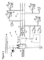
- FIG. 1 is a diagram of an electric power distribution system 10 that includes an electric vehicle charging system 20.
- electric vehicle charging system 20 includes a plurality of electric vehicle charging apparatus 30 and a central processing device 32.
- the plurality of electric vehicle charging apparatus 30 includes a first electric vehicle charging apparatus 40, a second electric vehicle charging apparatus 42, a third electric vehicle charging apparatus 44, and a fourth electric vehicle charging apparatus 46.
- electric vehicle charging system 20 may include any number of electric vehicle charging apparatus that allows system 20 to function as described herein.
- apparatus 40, 42, 44, and 46 may also be referred to as electric vehicle charging stations (EVCS).
- EVCS electric vehicle charging stations
- first EVCS 40 is positioned at a first location 50
- second EVCS 42 is positioned at a second location 52
- third EVCS 44 is positioned at a third location 54
- fourth EVCS 46 is positioned at a fourth location 56.
- locations 50, 52, 54, and 56 may be any location including, but not limited to, residential structures including houses and/or garages, commercial structures including parking lots, garages, and/or parking structures, municipal locations including parking lots, garages, parking structures, and/or street parking spots, or any other type of location where electric vehicle charging could be performed.
- distribution lines 60 provide electricity to a distribution transformer 62.
- Distribution transformer 62 steps down voltage provided by distribution lines 60 to a voltage level used by a consumer.
- distribution transformer 62 may be a ground-mounted transformer, integrated within a substation, or any other type of distribution transformer that allows system 20 to function as described herein.
- distribution transformer 62 is a single-phase transformer, although, in other embodiments, distribution transformer 62 may also include three-phases.
- distribution transformer 62 ranges in capacity from 5 kilovolt-ampere (kVA) to 150 kVA.
- distribution transformer 62 may have a capacity of 15 kVA to 25 kVA, which is a power level capable of supplying power to approximately seven to ten residential locations.
- distribution transformer 62 may include a 240 V secondary winding (not shown in Figure 1 ) that is center-tapped such that a first conductor 70 is neutral (i.e., grounded), a second conductor 72 and a third conductor 74 are "hot" with respect to first conductor 70.
- a connection between first conductor 70 and second conductor 72 provides 120 V
- a connection between first conductor 70 and third conductor 74 provides 120 V
- a connection between second conductor 72 and third conductor 74 provides 240 V.
- system 20 may be included within a 416Y/240 system or any other power distribution system that allows system 20 to function as described herein.
- the electric vehicle when charging an electric vehicle at the second power level, the electric vehicle may be the largest individual residential load drawing power from distribution transformer 62. For example, charging a single electric vehicle at the second power level represents approximately 7.2 kilowatt (kW) of load. Therefore, multiple EVCS coupled to distribution transformer 62 may cause distribution transformer 62 to exceed a predefined nominal load rating (kVA NOM ) and/or a predefined maximum load rating (kVA UL ). Exceeding these predefined load ratings may cause a reduction in the lifecycle of distribution transformer 62 (i.e., distribution transformer 62 will need to be replaced after a shorter period of use).
- kVA NOM nominal load rating
- kVA UL predefined maximum load rating
- central processing device 32 and each of the plurality of EVCS 30 include a communications device 80 configured to facilitate communication between central processing device 32 and each of the plurality of EVCS 30.
- communications device 80 transmits an identification signal from EVCS 40 to central processing device 32.
- the identification signal uniquely identifies EVCS 40 to central processing device 32.
- Central processing device 32 determines a number of EVCS coupled to distribution transformer 62 based on received identification signals.
- Communications device 80 may include a radio frequency identification device (RFID) and/or any other device facilitating communication between EVCS 40, 42, 44, and 46 and central processing device 32.
- RFID radio frequency identification device
- the plurality of EVCS 30 and central processing device 32 may be included within a network that includes wired and/or wireless components.
- Wireless components may be configured to use wireless standards including, but not limited to, 2G, 3G, and 4G cellular standards such as LTE, EDGE, and GPRS, IEEE 802.16 Wi-Max, IEEE 802.15 ZigBee®, Bluetooth, IEEE 802.11 standards including 802.11a, 802.11b, 802.11d, 802.11e, 802.11g, 802.11h, 802.111, 802.11j, and 802.11n, Wi-Fi®, and proprietary standards such as Z-Wave®.
- Wi-Fi® is a certification mark developed by the Wi-Fi Alliance, Inc. of Austin, TX
- ZigBee® is a registered trademark of ZigBee Alliance, Inc. of San Ramon, CA
- Z-Wave® is a registered trademark of Sigma Designs, Inc. of Milpitas, CA.
- system 20 also includes at least one sensor 82 configured to collect data and provide the data to central processing device 32.
- Central processing device 32 determines an electrical load presently drawn from distribution transformer 62 based on the received data.
- the at least one sensor 82 performs measurements that provide values from which the electrical load on distribution transformer 62 can be calculated.
- sensor 82 generates a load signal that includes data corresponding to the present electrical load on distribution transformer 62.
- Sensor 82 may be included within central processing device 32 or may be separate from, and coupled to, central processing device 32.
- central processing device 32 controls operation of plurality of EVCS 30. For example, central processing device 32 receives the load signal from sensor 82, receives a charging request from first EVCS 40, and provides first EVCS 40 with an electric power charging signal if it is determined that providing power to first EVCS 40 will not cause the present load on distribution transformer 62 to exceed the predefined nominal load rating of distribution transformer 62. For example, when a consumer couples an electric vehicle to first EVCS 40, first EVCS 40 generates and transmits a charging request to central processing device 32. Upon receipt of the charging request, central processing device 32 determines if providing power to first EVCS 40 will cause the present load on distribution transformer 62 to exceed the predefined nominal load rating.
- central processing device 32 may compare the present electrical load to a power available under the predefined nominal power rating for distribution transformer 62 to determine if providing power to first EVCS 40 will cause the present load on distribution transformer 62 to exceed the predefined nominal load rating of distribution transformer 62.
- central processing device 32 may also compare the present electrical load to a predefined maximum distribution transformer load rating if it is determined that providing power to first EVCS 40 will cause the present load on distribution transformer 62 to exceed the predefined nominal load rating.
- the predefined maximum distribution transformer load rating is defined by a utility company as the maximum load the utility company will allow to be placed on distribution transformer 62. In a typical example, the predefined maximum load rating is approximately 10% higher than the predefined nominal load rating.
- central processing device 32 may deny service to first EVCS 40 and place first EVCS 40 in a charging queue if it is determined that charging an electric vehicle at first EVCS 40 would cause the present electrical load on distribution transformer 62 to exceed the predefined maximum distribution transformer load rating.
- first EVCS 40 includes an input/output device 86 configured to display at least one charging option to a consumer and to receive at least one selection from the consumer.
- input/output device 86 may include a touch screen that displays charging options to a consumer and receives a selection from the consumer.
- input/output device 86 may include a display screen and an input device, or any other combination of input and output devices, that allow system 20 to function as described herein.
- central processing device 32 may transmit a charging option selection signal to first EVCS 40 if it is determined that providing power to first EVCS 40 will not cause the present load on distribution transformer 62 to exceed the predefined maximum distribution transformer load rating.
- input/output device 86 displays the charging options to the consumer.
- central processing device 32 receives, from input/output device 86, at least one of a charge-delay signal and a charge-now signal.
- the charging options include choosing between waiting to begin charging the electric vehicle at a first monetary rate, referred to herein as a charge-delay selection, or charging the electric vehicle now at a second, higher monetary rate, referred to herein as a charge-now selection.
- the first monetary rate may be a time-of-use rate, substantially similar to the rate the consumer typically pays for electricity at the time the charge is requested.
- the second monetary rate may be higher than the typical time-of-use rate, wherein the utility company is essentially offering the consumer the option of charging their vehicle without waiting in exchange for paying a higher rate for the electricity used to charge the vehicle.
- the second monetary rate may be determined to offset increased costs and/or value lost by the utility due to the reduction in the lifecycle of distribution transformer 62 caused by applying a load to distribution transformer 62 that exceeds the nominal load rating of distribution transformer 62.
- central processing device 32 is further configured to determine the second monetary rate (i.e., the energy rate associated with the charge-now selection) and to include data corresponding to at least one of the first monetary rate and the second monetary rate within the charging option selection signal provided to input/output device 86.
- the second monetary rate may be determined based at least partially on a signal received from the utility that includes rate information.
- the second monetary rate may also be determined based at least partially on tables stored and accessible by central processing device 32, and/or determined in any other manner that allows system 20 to function as described herein.
- the monetary rate(s) are then displayed by input/output device 86, and the consumer is able to make their decision on when to charge their electric vehicle with the added knowledge of the rates associated with one, or both, charging options.
- FIG 2 is a flow chart 100 of an exemplary method 102 for controlling an electric vehicle charging system, for example, electric vehicle charging system 20 shown in Figure 1 .
- method 102 includes registering 108 the EVCSs that are coupled to a distribution transformer, for example, plurality of EVCS 30 (shown in Figure 1 ) that are coupled to distribution transformer 62 (shown in Figure 1 ).
- central processing device 32 receives identification signals from each of the plurality of EVCS 30 and registers 108 each EVCS coupled to distribution transformer 62.
- method 102 also includes receiving 110 a charge request signal.
- central processing device 32 may receive 110 a charge request signal from first EVCS 40.
- Method 102 also includes measuring 112 a present electrical load (kVA M ) on distribution transformer 62. Measuring 112 may include receiving, at central processing device 32, a measurement from a sensor, for example, sensor 82 (shown in Figure 1 ). Method 102 may also include determining 114 if there are any EVCS waiting to receive an electric power charging signal (i.e., are any EVCS presently in a charging queue).
- kVA M present electrical load
- method 102 includes determining 116 if providing power to an EVCS will cause distribution transformer 62 to exceed a predefined nominal load rating (kVA NOM ). For example, upon receiving 110 a charge request signal from first EVCS 40, central processing device 32 determines 116 if providing power to first EVCS 40 will cause the present load on distribution transformer 62 to exceed the predefined nominal load rating.
- kVA NOM a predefined nominal load rating
- central processing device 32 determines an available power (kVA A ).
- the available power is a power that if exceeded, will cause distribution transformer 62 to reach the predefined nominal load rating of distribution transformer 62.
- the available power may be calculated by subtracting the present electrical load (kVA M ) from the predefined nominal load rating (kVA NOM ) of distribution transformer 62.
- determining 116 includes comparing the available power (kVA A ) to a typical power drawn by EVCS 40. If central processing device 32 determines 116 that the available power (kVA A ) is greater than the typical power drawn by EVCS 40, then a determination is made that providing power to EVCS 40 will not cause distribution transformer 62 to exceed the predefined nominal load rating (kVA NOM ). If central processing device 32 determines 116 that the available power (kVA A ) is less than the typical power drawn by EVCS 40, then a determination is made that providing power to EVCS 40 will cause distribution transformer 62 to exceed the predefined nominal load rating (kVA NOM ).
- Central processing device 32 may be programmed to determine 116 that providing power to EVCS 40 will, or will not, cause the present electrical load (kVA M ) on distribution transformer 62 to exceed the predefined nominal load rating (kVA NOM ) when the available power (kVA A ) is equal to the typical power drawn by EVCS 40.
- EVCS 40 may draw 7.2 kW of power for use in charging a vehicle. If kVA M is less than kVA NOM -7.2kW, then a determination is made that providing power to EVCS 40 will not cause the present load on distribution transformer 62 to exceed the predefined nominal load rating.
- method 102 includes assigning 118 first EVCS 40 to a first available charging slot and charging the consumer for the electricity at a first energy rate (e.g., a time-of-use energy rate typically charged to the consumer for electricity). Assigning 118 first EVCS 40 to a first available charging slot includes providing first EVCS 40 with an electric power charging signal.
- kVA NOM predefined nominal load rating
- method 102 also includes determining 130 if providing power to first EVCS 40 will cause the load on distribution transformer 62 to exceed a predefined maximum distribution transformer load rating (kVA UL ).
- kVA UL the predefined maximum distribution transformer load rating
- central processing device 32 determines 130 if the present electrical load (kVA M ) on distribution transformer 62 is less than the maximum load rating (kVA UL ) of distribution transformer 62 minus a typical power drawn by EVCS 40 (e.g., 7.2 kW).
- central processing device 32 determines 114 there is at least one EVCS in the charging queue, central processing device 32 also determines 130 if providing power to the at least one EVCS in the charging queue will cause the load on distribution transformer 62 to exceed the predefined maximum distribution transformer load rating (kVA UL ).
- method 102 includes denying 132 service to first EVCS 40 and placing first EVCS 40 in the charging queue.
- method 102 includes denying 132 service to first EVCS 40 and maintaining the position of first EVCS 40 in the charging queue.
- First EVCS 40 remains in the charging queue until the present electrical load (kVA M ) on distribution transformer 62 is at a level where providing power to first EVCS 40 will not cause the load on distribution transformer 62 to exceed the predefined maximum distribution transformer load rating (kVA UL ).
- method 102 includes providing 134 a charging option to a consumer, for example, by providing a charging option selection signal to a display, for example, input/output device 86 (shown in Figure 1 ).
- Input/output device 86 provides the charging option to the consumer.
- the charging option may give the consumer the choice of a charge-now selection and a charge-delay selection.
- EVCS 40, and more specifically, input/output device 86 may receive an input from the consumer corresponding to a selection of either the charge-now selection or the charge-delay selection.
- EVCS 40 generates a charge-now signal upon receipt of the charge-now selection, or generates a charge-delay signal upon receipt of the charge-delay selection, and transmits the charge-now signal or charge-delay signal to central processing device 32.
- charging of the electric vehicle begins at the time the charge-now signal is received by central processing device 32 and the consumer is charged a higher than time-of-use rate. If the consumer selects the charge-delay selection, charging of the electric vehicle begins after the present load on distribution transformer 62 decreases to a level where charging the electric vehicle at EVCS 40 would not cause the present load on distribution transformer 62 to exceed the nominal load rating. If the consumer selects the charge-delay selection, method 102 includes delaying 138 service to first EVCS 40 until the present load on distribution transformer 62 decreases. After the delay, central processing device 32 transmits 140 the electric power charging signal to first EVCS 40 and the consumer is charged a typical time-of-use rate. Alternatively, if the consumer selects the charge-now selection, method 102 includes providing 142 the electric power charging signal to first EVCS 40 upon receipt of the charge-now signal.
- FIG 3 is a block diagram of an exemplary embodiment of a processing device 200 that may be included within electric vehicle charging system 20 (shown in Figure 1 ), and more specifically, within central processing device 32 (shown in Figure 1 ).
- Central processing device 32 is configured to perform operations associated with method 102 (shown in Figure 2 ).
- Processing device 200 may also be referred to as a system controller and/or a smart device data concentrator.
- processing device 200 includes a bus 210 or other communications device to communicate information.
- One or more processor(s) 212 are coupled to bus 210 to process information, including data received from, for example, but not limited to, sensor 82 (shown in Figure 1 ) and/or input/output device 86 (shown in Figure 1 ).
- processor broadly refers to a processor, a microcontroller, a microcomputer, a programmable logic controller (PLC), an application specific integrated circuit, and other programmable circuits, and these terms are used interchangeably herein.
- processor(s) 212 may be included within a computer. Aspects of the disclosure transform a general-purpose computer into a special-purpose computing device when configured to execute the instructions described herein.
- Processing device 200 may also include one or more random access memories (RAM) 214 and/or other storage device(s) 216.
- RAM(s) 214 and storage device(s) 216 are coupled to bus 210 to store and transfer information and instructions to be executed by processor(s) 212.
- RAM(s) 214 (and/or storage device(s) 216, if included) can also be used to store temporary variables or other intermediate information during execution of instructions by processor(s) 212.
- Processing device 200 may also include one or more read only memories (ROM) 218 and/or other static storage devices coupled to bus 210 to store and provide static (i.e., non-changing) information and instructions to processor(s) 212.
- ROM read only memories
- static information may include, but is not limited to, a predefined maximum load rating and a predefined nominal load rating for a distribution transformer.
- Instructions that are executed include, without limitation, resident conversion and/or comparator algorithms. The execution of sequences of instructions is not limited to any specific combination of hardware circuitry and software instructions.
- Processing device 200 may also include, or may be coupled to, input/output device(s) 220.
- Input/output device(s) 220 may include, or be coupled to, any device known in the art to provide input data to processing device 200 and/or to provide outputs, such as, but not limited to, an electric power charging signal.
- Instructions may be provided to RAM 214 from storage device 216 including, for example, a magnetic disk, a read-only memory (ROM) integrated circuit, CD-ROM, and/or DVD, via a remote connection that is either wired or wireless providing access to one or more electronically-accessible media.
- ROM read-only memory
- hard-wired circuitry can be used in place of or in combination with software instructions.
- input/output device(s) 220 may include, without limitation, computer peripherals associated with an operator interface (e.g., a human machine interface (HMI)) such as a mouse and a keyboard (neither shown in Figure 3 ), and/or input/output device 86 (shown in Figure 1 ).
- operator interface e.g., a human machine interface (HMI)
- HMI human machine interface
- additional output channels may include, for example, an operator interface monitor and/or alarm device (neither shown in Figure 3 ).
- Processing device 200 may also include a sensor interface 222 that allows processing device 200 to communicate with sensors, for example, sensor 82 (shown in Figure 1 ).
- Sensor interface 222 may include one or more analog-to-digital converter that converts analog signals into digital signals that can be used by processor(s) 212.
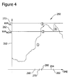
- FIG 4 is a graph 250 of exemplary load levels 252 on a distribution transformer, for example, distribution transformer 62 (shown in Figure 1 ) over time 254.
- a first electric vehicle is coupled to electric vehicle charging system 20 (shown in Figure 1 ), for example, at first EVCS 40 (shown in Figure 1 ).
- Central processing device 32 determines that charging the first vehicle would not cause the load 252 on distribution transformer 62 to exceed a nominal load rating 262 for distribution transformer 62. Accordingly, an electric power charging signal is transmitted by central processing device 32 to first EVCS 40 and charging of the first vehicle begins.
- first vehicle continues to draw power from distribution transformer 62, and a second vehicle is coupled to electric vehicle charging system 20, for example, at second EVCS 42 (shown in Figure 1 ).
- Central processing device 32 determines that charging the second vehicle would cause the load 252 on distribution transformer 62 to exceed nominal load rating 262, but would not cause the load 252 on distribution transformer 62 to exceed a predefined maximum load rating 272 for distribution transformer 62.
- the consumer would like to begin charging the second vehicle now, and is willing to pay a rate that is higher than a typical time-of-use rate, in order to begin charging the second vehicle now.
- the consumer selects the charge-now option, and the electric charging signal is provided to second EVCS 42, the electric vehicle begins charging, and the load 252 on distribution transformer 62 increases.
- a third electric vehicle is coupled to electric vehicle charging system 20, for example, at third EVCS 44 (shown in Figure 1 ).
- Central processing device 32 determines that charging the third vehicle would cause the load 252 on distribution transformer 62 to exceed nominal load rating 262, and would cause the load 252 on distribution transformer 62 to exceed the predefined maximum load rating 272 for distribution transformer 62.
- Central processing device 32 places third EVCS 44 in a charging queue to prevent load 252 from exceeding the predefined maximum load rating 272.
- the load 252 on distribution transformer 62 has decreased to a level where providing power to third EVCS 44 would not cause the load 252 on distribution transformer 62 to exceed the predefined maximum load rating 272.
- third EVCS 44 is not assigned to the first available slot at a typical time-of-use rate, rather, the consumer is provided with a charging option.
- the consumer would like to begin charging the third vehicle now, and is willing to pay a rate that is higher than the typical time-of-use rate, in order to begin charging the third vehicle now. Therefore, the consumer selects the charge-now selection and the electric charging signal is provided to third EVCS 44, and load 252 increases during charging of the third electric vehicle.
- Described herein are exemplary methods and systems for controlling an electric vehicle charging system that includes a plurality of electric vehicle charging apparatus. More specifically, the methods and systems described herein facilitate determining a charging order for a plurality of electric vehicles coupled to a distribution transformer based at least partially on a comparison of a present electrical load on the distribution transformer to at least one of power available under a predefined nominal power rating for the distribution transformer and a predefined maximum distribution transformer load rating. Controlling the charging of electric vehicles facilitates maintaining the load on the distribution transformer below an upper power limit, which maximizes a lifecycle of the distribution transformer. Furthermore, the methods and systems described herein provide a consumer with charging options that take into consideration a monetary electric rate charged by the utility company and the time that the vehicle is charged.
- the articles “a”, “an”, “the”, and “said” are intended to mean that there are one or more of the element(s)/component(s)/etc.
- the terms “comprising”, “including”, and “having” are intended to be inclusive and mean that there may be additional element(s)/component(s)/etc. other than the listed element(s)/component(s)/etc.
Landscapes
- Engineering & Computer Science (AREA)
- Power Engineering (AREA)
- Transportation (AREA)
- Mechanical Engineering (AREA)
- Charge And Discharge Circuits For Batteries Or The Like (AREA)
- Electric Propulsion And Braking For Vehicles (AREA)
- Remote Monitoring And Control Of Power-Distribution Networks (AREA)
- Secondary Cells (AREA)
Applications Claiming Priority (1)
| Application Number | Priority Date | Filing Date | Title |
|---|---|---|---|
| US13/044,070 US8680812B2 (en) | 2011-03-09 | 2011-03-09 | Methods and systems for charging an electric vehicle |
Publications (3)
| Publication Number | Publication Date |
|---|---|
| EP2497678A2 true EP2497678A2 (fr) | 2012-09-12 |
| EP2497678A3 EP2497678A3 (fr) | 2015-07-01 |
| EP2497678B1 EP2497678B1 (fr) | 2019-05-22 |
Family
ID=45768150
Family Applications (1)
| Application Number | Title | Priority Date | Filing Date |
|---|---|---|---|
| EP12158055.9A Active EP2497678B1 (fr) | 2011-03-09 | 2012-03-05 | Procédés et systèmes de chargement d'un véhicule électrique |
Country Status (7)
| Country | Link |
|---|---|
| US (1) | US8680812B2 (fr) |
| EP (1) | EP2497678B1 (fr) |
| JP (1) | JP2012191843A (fr) |
| CN (1) | CN102684251B (fr) |
| AU (1) | AU2012201373A1 (fr) |
| BR (1) | BR102012004550A2 (fr) |
| CA (1) | CA2769945A1 (fr) |
Cited By (4)
| Publication number | Priority date | Publication date | Assignee | Title |
|---|---|---|---|---|
| WO2014079867A1 (fr) * | 2012-11-26 | 2014-05-30 | Siemens Aktiengesellschaft | Procédé de commande assistée par ordinateur d'un réseau de distribution d'énergie électrique composé d'une pluralité de nœuds |
| WO2016031095A1 (fr) * | 2014-08-25 | 2016-03-03 | Toyota Jidosha Kabushiki Kaisha | Service de commande de charge régional |
| EP3375658A3 (fr) * | 2017-03-16 | 2018-12-26 | Dr. Ing. h.c. F. Porsche AG | Système de station de charge pour véhicules électriques |
| WO2020193068A1 (fr) * | 2019-03-28 | 2020-10-01 | Siemens Aktiengesellschaft | Dispositif de transmission d'énergie électrique |
Families Citing this family (30)
| Publication number | Priority date | Publication date | Assignee | Title |
|---|---|---|---|---|
| US8924033B2 (en) | 2010-05-12 | 2014-12-30 | Alstom Grid Inc. | Generalized grid security framework |
| US10778008B2 (en) * | 2011-03-28 | 2020-09-15 | Paul S. Levy | Method and process for acquiring and delivering electric vehicle owner-operator preference data which is used to schedule and regulate the charging of multiple electric vehicle batteries within a shared local power distribution network |
| JP6012144B2 (ja) * | 2011-05-20 | 2016-10-25 | パナソニックエコソリューションズ電路株式会社 | 充電制御システム |
| US9505318B2 (en) | 2011-05-26 | 2016-11-29 | Sierra Smart Systems, Llc | Electric vehicle fleet charging system |
| US8706312B2 (en) * | 2011-06-02 | 2014-04-22 | General Electric Company | Charging device and methods of authorizing a charging request |
| US9281689B2 (en) | 2011-06-08 | 2016-03-08 | General Electric Technology Gmbh | Load phase balancing at multiple tiers of a multi-tier hierarchical intelligent power distribution grid |
| US8965590B2 (en) | 2011-06-08 | 2015-02-24 | Alstom Grid Inc. | Intelligent electrical distribution grid control system data |
| US9641026B2 (en) * | 2011-06-08 | 2017-05-02 | Alstom Technology Ltd. | Enhanced communication infrastructure for hierarchical intelligent power distribution grid |
| US20130026986A1 (en) * | 2011-07-26 | 2013-01-31 | Honeywell International Inc. | Transformer-level management of power consumption by one or more consumers |
| US20130073483A1 (en) * | 2011-09-16 | 2013-03-21 | General Electric Company | Systems, Methods, and Apparatus for Protecting Power Transformers |
| JP6037013B2 (ja) * | 2013-06-25 | 2016-11-30 | 日本電気株式会社 | 充電状態管理方法、充電状態管理装置およびプログラム |
| US9995768B2 (en) | 2013-08-28 | 2018-06-12 | San Diego Gas & Electric | Interconnection meter socket adapters |
| US10089641B2 (en) | 2013-08-28 | 2018-10-02 | San Diego Gas & Electric Company | Interconnect socket adapter for adapting one or more power sources and power sinks |
| US9772347B2 (en) | 2013-08-28 | 2017-09-26 | San Diego Gas & Electric Company | Interconnection meter socket adapters |
| US10132838B2 (en) | 2013-08-28 | 2018-11-20 | San Diego Gas & Electric Company | Managing power source interaction through an interconnect socket adapter configured with an energy storage source/sink |
| US9904308B2 (en) * | 2013-08-28 | 2018-02-27 | San Diego Gas & Electric Company | Managing power source interaction through an interconnect socket adapter configured with an electric vehicle sink |
| KR101459968B1 (ko) * | 2013-11-19 | 2014-11-10 | 현대자동차주식회사 | 전기자동차 충전 요구량 검증 방법 및 이에 사용되는 시스템 |
| DK3119638T3 (en) | 2014-03-20 | 2018-03-26 | Evercharge Inc | INTELLIGENT ENERGY DISTRIBUTION METHODS AND SYSTEMS FOR CHARGING ELECTRIC VEHICLES |
| US10262536B2 (en) * | 2015-06-03 | 2019-04-16 | Ford Global Technologies, Llc | Method and apparatus for charging station monitoring |
| WO2017189882A1 (fr) * | 2016-04-27 | 2017-11-02 | San Diego Gas & Electric Company | Gestion d'interaction de source d'alimentation par l'intermédiaire d'un support adaptateur à interconnexion conçu avec un collecteur de véhicule électrique |
| CN106143180B (zh) * | 2016-06-13 | 2019-01-22 | 通用电气技术有限公司 | 电动车分散充电控制系统和方法 |
| KR101978133B1 (ko) * | 2017-04-05 | 2019-05-15 | 한국전력공사 | 배전선로에 연계된 변압기의 부하량에 기초한 전주에 설치된 전기차 충전 장치, 전기차 충전 시스템 및 전주에 설치된 전기차 충전 장치 제어 방법 |
| KR102027983B1 (ko) * | 2017-04-05 | 2019-10-04 | 한국전력공사 | 지상변압기를 이용한 전기차 충전 장치 및 전기차 충전 방법 |
| CN108075536B (zh) * | 2017-11-10 | 2021-10-19 | 深圳供电局有限公司 | 充电桩的柔性充电调控方法及充电桩系统 |
| JP7070083B2 (ja) * | 2018-05-21 | 2022-05-18 | トヨタ自動車株式会社 | 管理サーバ、情報処理方法および情報処理システム |
| DE102019117582A1 (de) * | 2019-06-28 | 2020-12-31 | Sma Solar Technology Ag | Verfahren und system zur koordination von ladevorgängen für elektrofahrzeuge |
| US11772504B2 (en) * | 2019-08-22 | 2023-10-03 | Ioan Sasu | Fast rechargeable battery assembly and recharging equipment |
| CN111211564B (zh) * | 2020-01-17 | 2021-06-04 | 南京东博智慧能源研究院有限公司 | 一种考虑电动汽车充电负荷时空分布的需求响应方法 |
| CN112421739B (zh) * | 2020-04-24 | 2024-01-02 | 葛炽昌 | 电动车交流充电系统 |
| JP7459841B2 (ja) | 2021-06-02 | 2024-04-02 | トヨタ自動車株式会社 | 車両、及び充電方法 |
Family Cites Families (12)
| Publication number | Priority date | Publication date | Assignee | Title |
|---|---|---|---|---|
| US5926004A (en) * | 1997-10-10 | 1999-07-20 | Schott Power Systems Incorporated | Method and apparatus for charging one or more electric vehicles |
| US7795877B2 (en) * | 2006-11-02 | 2010-09-14 | Current Technologies, Llc | Power line communication and power distribution parameter measurement system and method |
| US7693609B2 (en) * | 2007-09-05 | 2010-04-06 | Consolidated Edison Company Of New York, Inc. | Hybrid vehicle recharging system and method of operation |
| US8054048B2 (en) | 2007-10-04 | 2011-11-08 | GM Global Technology Operations LLC | Power grid load management for plug-in vehicles |
| US8266075B2 (en) | 2008-06-16 | 2012-09-11 | International Business Machines Corporation | Electric vehicle charging transaction interface for managing electric vehicle charging transactions |
| US7991665B2 (en) | 2008-06-16 | 2011-08-02 | International Business Machines Corporation | Managing incentives for electric vehicle charging transactions |
| US20090313034A1 (en) | 2008-06-16 | 2009-12-17 | International Business Machines Corporation | Generating Dynamic Energy Transaction Plans |
| US9751416B2 (en) | 2008-06-16 | 2017-09-05 | International Business Machines Corporation | Generating energy transaction plans |
| US8085034B2 (en) * | 2008-10-31 | 2011-12-27 | Yaniv Sirton | Managing charging of electric vehicles |
| US8143842B2 (en) * | 2008-12-05 | 2012-03-27 | Lava Four, Llc | Dynamic load management for use in recharging vehicles equipped with electrically powered propulsion systems |
| US20100228404A1 (en) * | 2009-03-06 | 2010-09-09 | Link Ii Charles M | Method and system for configuring and provisioning a vehicle |
| US20100280675A1 (en) | 2009-04-30 | 2010-11-04 | Gm Global Technology Operations, Inc. | Method for managing electric vehicle charging loads on a local electric power infrastructure |
-
2011
- 2011-03-09 US US13/044,070 patent/US8680812B2/en active Active
-
2012
- 2012-02-29 BR BRBR102012004550-8A patent/BR102012004550A2/pt not_active IP Right Cessation
- 2012-03-01 CA CA 2769945 patent/CA2769945A1/fr not_active Abandoned
- 2012-03-05 EP EP12158055.9A patent/EP2497678B1/fr active Active
- 2012-03-07 AU AU2012201373A patent/AU2012201373A1/en not_active Abandoned
- 2012-03-08 JP JP2012051111A patent/JP2012191843A/ja active Pending
- 2012-03-09 CN CN201210070695.1A patent/CN102684251B/zh active Active
Non-Patent Citations (1)
| Title |
|---|
| None |
Cited By (6)
| Publication number | Priority date | Publication date | Assignee | Title |
|---|---|---|---|---|
| WO2014079867A1 (fr) * | 2012-11-26 | 2014-05-30 | Siemens Aktiengesellschaft | Procédé de commande assistée par ordinateur d'un réseau de distribution d'énergie électrique composé d'une pluralité de nœuds |
| WO2016031095A1 (fr) * | 2014-08-25 | 2016-03-03 | Toyota Jidosha Kabushiki Kaisha | Service de commande de charge régional |
| US9789779B2 (en) | 2014-08-25 | 2017-10-17 | Toyota Jidosha Kabushiki Kaisha | Regional charging control service |
| EP3375658A3 (fr) * | 2017-03-16 | 2018-12-26 | Dr. Ing. h.c. F. Porsche AG | Système de station de charge pour véhicules électriques |
| US10457153B2 (en) | 2017-03-16 | 2019-10-29 | Dr. Ing. H.C. F. Porsche Aktiengesellschaft | Charging station system for electric vehicles with interconnections between power and cooling main components |
| WO2020193068A1 (fr) * | 2019-03-28 | 2020-10-01 | Siemens Aktiengesellschaft | Dispositif de transmission d'énergie électrique |
Also Published As
| Publication number | Publication date |
|---|---|
| CN102684251A (zh) | 2012-09-19 |
| EP2497678A3 (fr) | 2015-07-01 |
| JP2012191843A (ja) | 2012-10-04 |
| BR102012004550A2 (pt) | 2013-10-22 |
| AU2012201373A1 (en) | 2012-09-27 |
| CN102684251B (zh) | 2014-10-22 |
| US20120229082A1 (en) | 2012-09-13 |
| EP2497678B1 (fr) | 2019-05-22 |
| US8680812B2 (en) | 2014-03-25 |
| CA2769945A1 (fr) | 2012-09-09 |
Similar Documents
| Publication | Publication Date | Title |
|---|---|---|
| US8680812B2 (en) | Methods and systems for charging an electric vehicle | |
| Muñoz et al. | Electric vehicle charging algorithms for coordination of the grid and distribution transformer levels | |
| TWI499159B (zh) | 控制充電站之方法、與相關充電站、低電壓變電站及系統 | |
| CN102891505B (zh) | 充电设备、智能运输工具充电系统及其操作方法 | |
| RU2550109C2 (ru) | Система, устройство и способ обмена энергией с электротранспортным средством | |
| CN107528313B (zh) | 一种充电站的功率监控方法、装置及系统 | |
| US20130046411A1 (en) | Electric Vehicle Load Management | |
| CN105109357A (zh) | 一种电动汽车智能充电系统及方法 | |
| US20130257372A1 (en) | Intelligent electric vehicle recharging | |
| US11117487B2 (en) | Communication-free charge controller for electric vehicles | |
| CN108847700B (zh) | 一种应用于电动汽车的充电用分时共享电源及其监控系统 | |
| Markel | Plug-in electric vehicle infrastructure: A foundation for electrified transportation | |
| WO2011156776A2 (fr) | Appareil et procédés d'intégration au réseau et de charge de véhicule électrique (ev) intelligent | |
| KR20160012355A (ko) | 전기자동차 충전 및 역전송 전력 운영시스템 | |
| JP6582737B2 (ja) | 充放電制御装置及び制御プログラム | |
| Kumar et al. | Impact of demand response management on chargeability of electric vehicles | |
| CN108923485B (zh) | 一种居民小区充电桩功率控制方法 | |
| JP2021035171A (ja) | 充電制御装置及びその方法、プログラム、充電管理装置及びその方法、プログラム | |
| Bohn et al. | Local automatic load control for electric vehicle smart charging systems extensible via OCPP using compact submeters | |
| Reiner et al. | Distributed self organising electric vehicle charge controller system: Peak power demand and grid load reduction with adaptive ev charging stations | |
| JP7136041B2 (ja) | 車両管理装置、車両および車両管理方法 | |
| CN114290936B (zh) | 一种充电控制方法、充电系统及相关设备 | |
| CN110682823A (zh) | 一种电动汽车充电控制方法及系统 | |
| Gödde et al. | Approach and main results of the G4V project analyzing the impact of a mass introduction of electric vehicles on electricity networks in Europe | |
| Schultis et al. | Coordinated Electric Vehicle Charging-Performance Analysis Of Developed Algorithms |
Legal Events
| Date | Code | Title | Description |
|---|---|---|---|
| PUAI | Public reference made under article 153(3) epc to a published international application that has entered the european phase |
Free format text: ORIGINAL CODE: 0009012 |
|
| AK | Designated contracting states |
Kind code of ref document: A2 Designated state(s): AL AT BE BG CH CY CZ DE DK EE ES FI FR GB GR HR HU IE IS IT LI LT LU LV MC MK MT NL NO PL PT RO RS SE SI SK SM TR |
|
| AX | Request for extension of the european patent |
Extension state: BA ME |
|
| PUAL | Search report despatched |
Free format text: ORIGINAL CODE: 0009013 |
|
| AK | Designated contracting states |
Kind code of ref document: A3 Designated state(s): AL AT BE BG CH CY CZ DE DK EE ES FI FR GB GR HR HU IE IS IT LI LT LU LV MC MK MT NL NO PL PT RO RS SE SI SK SM TR |
|
| AX | Request for extension of the european patent |
Extension state: BA ME |
|
| RIC1 | Information provided on ipc code assigned before grant |
Ipc: B60L 11/18 20060101AFI20150526BHEP Ipc: H02J 3/06 20060101ALI20150526BHEP Ipc: H02J 13/00 20060101ALI20150526BHEP Ipc: H02J 7/00 20060101ALI20150526BHEP |
|
| 17P | Request for examination filed |
Effective date: 20160104 |
|
| RBV | Designated contracting states (corrected) |
Designated state(s): AL AT BE BG CH CY CZ DE DK EE ES FI FR GB GR HR HU IE IS IT LI LT LU LV MC MK MT NL NO PL PT RO RS SE SI SK SM TR |
|
| RAP1 | Party data changed (applicant data changed or rights of an application transferred) |
Owner name: FISCHER, JENS PETER |
|
| 17Q | First examination report despatched |
Effective date: 20160603 |
|
| RAP1 | Party data changed (applicant data changed or rights of an application transferred) |
Owner name: GENERAL ELECTRIC COMPANY |
|
| STAA | Information on the status of an ep patent application or granted ep patent |
Free format text: STATUS: EXAMINATION IS IN PROGRESS |
|
| GRAP | Despatch of communication of intention to grant a patent |
Free format text: ORIGINAL CODE: EPIDOSNIGR1 |
|
| STAA | Information on the status of an ep patent application or granted ep patent |
Free format text: STATUS: GRANT OF PATENT IS INTENDED |
|
| INTG | Intention to grant announced |
Effective date: 20181212 |
|
| GRAS | Grant fee paid |
Free format text: ORIGINAL CODE: EPIDOSNIGR3 |
|
| GRAA | (expected) grant |
Free format text: ORIGINAL CODE: 0009210 |
|
| STAA | Information on the status of an ep patent application or granted ep patent |
Free format text: STATUS: THE PATENT HAS BEEN GRANTED |
|
| AK | Designated contracting states |
Kind code of ref document: B1 Designated state(s): AL AT BE BG CH CY CZ DE DK EE ES FI FR GB GR HR HU IE IS IT LI LT LU LV MC MK MT NL NO PL PT RO RS SE SI SK SM TR |
|
| REG | Reference to a national code |
Ref country code: GB Ref legal event code: FG4D |
|
| REG | Reference to a national code |
Ref country code: CH Ref legal event code: EP |
|
| REG | Reference to a national code |
Ref country code: IE Ref legal event code: FG4D |
|
| REG | Reference to a national code |
Ref country code: DE Ref legal event code: R096 Ref document number: 602012060293 Country of ref document: DE |
|
| REG | Reference to a national code |
Ref country code: AT Ref legal event code: REF Ref document number: 1135686 Country of ref document: AT Kind code of ref document: T Effective date: 20190615 |
|
| REG | Reference to a national code |
Ref country code: NL Ref legal event code: MP Effective date: 20190522 |
|
| REG | Reference to a national code |
Ref country code: LT Ref legal event code: MG4D |
|
| PG25 | Lapsed in a contracting state [announced via postgrant information from national office to epo] |
Ref country code: FI Free format text: LAPSE BECAUSE OF FAILURE TO SUBMIT A TRANSLATION OF THE DESCRIPTION OR TO PAY THE FEE WITHIN THE PRESCRIBED TIME-LIMIT Effective date: 20190522 Ref country code: NO Free format text: LAPSE BECAUSE OF FAILURE TO SUBMIT A TRANSLATION OF THE DESCRIPTION OR TO PAY THE FEE WITHIN THE PRESCRIBED TIME-LIMIT Effective date: 20190822 Ref country code: HR Free format text: LAPSE BECAUSE OF FAILURE TO SUBMIT A TRANSLATION OF THE DESCRIPTION OR TO PAY THE FEE WITHIN THE PRESCRIBED TIME-LIMIT Effective date: 20190522 Ref country code: SE Free format text: LAPSE BECAUSE OF FAILURE TO SUBMIT A TRANSLATION OF THE DESCRIPTION OR TO PAY THE FEE WITHIN THE PRESCRIBED TIME-LIMIT Effective date: 20190522 Ref country code: AL Free format text: LAPSE BECAUSE OF FAILURE TO SUBMIT A TRANSLATION OF THE DESCRIPTION OR TO PAY THE FEE WITHIN THE PRESCRIBED TIME-LIMIT Effective date: 20190522 Ref country code: PT Free format text: LAPSE BECAUSE OF FAILURE TO SUBMIT A TRANSLATION OF THE DESCRIPTION OR TO PAY THE FEE WITHIN THE PRESCRIBED TIME-LIMIT Effective date: 20190922 Ref country code: ES Free format text: LAPSE BECAUSE OF FAILURE TO SUBMIT A TRANSLATION OF THE DESCRIPTION OR TO PAY THE FEE WITHIN THE PRESCRIBED TIME-LIMIT Effective date: 20190522 Ref country code: LT Free format text: LAPSE BECAUSE OF FAILURE TO SUBMIT A TRANSLATION OF THE DESCRIPTION OR TO PAY THE FEE WITHIN THE PRESCRIBED TIME-LIMIT Effective date: 20190522 Ref country code: NL Free format text: LAPSE BECAUSE OF FAILURE TO SUBMIT A TRANSLATION OF THE DESCRIPTION OR TO PAY THE FEE WITHIN THE PRESCRIBED TIME-LIMIT Effective date: 20190522 |
|
| PG25 | Lapsed in a contracting state [announced via postgrant information from national office to epo] |
Ref country code: BG Free format text: LAPSE BECAUSE OF FAILURE TO SUBMIT A TRANSLATION OF THE DESCRIPTION OR TO PAY THE FEE WITHIN THE PRESCRIBED TIME-LIMIT Effective date: 20190822 Ref country code: RS Free format text: LAPSE BECAUSE OF FAILURE TO SUBMIT A TRANSLATION OF THE DESCRIPTION OR TO PAY THE FEE WITHIN THE PRESCRIBED TIME-LIMIT Effective date: 20190522 Ref country code: LV Free format text: LAPSE BECAUSE OF FAILURE TO SUBMIT A TRANSLATION OF THE DESCRIPTION OR TO PAY THE FEE WITHIN THE PRESCRIBED TIME-LIMIT Effective date: 20190522 Ref country code: GR Free format text: LAPSE BECAUSE OF FAILURE TO SUBMIT A TRANSLATION OF THE DESCRIPTION OR TO PAY THE FEE WITHIN THE PRESCRIBED TIME-LIMIT Effective date: 20190823 |
|
| REG | Reference to a national code |
Ref country code: AT Ref legal event code: MK05 Ref document number: 1135686 Country of ref document: AT Kind code of ref document: T Effective date: 20190522 |
|
| PG25 | Lapsed in a contracting state [announced via postgrant information from national office to epo] |
Ref country code: CZ Free format text: LAPSE BECAUSE OF FAILURE TO SUBMIT A TRANSLATION OF THE DESCRIPTION OR TO PAY THE FEE WITHIN THE PRESCRIBED TIME-LIMIT Effective date: 20190522 Ref country code: SK Free format text: LAPSE BECAUSE OF FAILURE TO SUBMIT A TRANSLATION OF THE DESCRIPTION OR TO PAY THE FEE WITHIN THE PRESCRIBED TIME-LIMIT Effective date: 20190522 Ref country code: RO Free format text: LAPSE BECAUSE OF FAILURE TO SUBMIT A TRANSLATION OF THE DESCRIPTION OR TO PAY THE FEE WITHIN THE PRESCRIBED TIME-LIMIT Effective date: 20190522 Ref country code: EE Free format text: LAPSE BECAUSE OF FAILURE TO SUBMIT A TRANSLATION OF THE DESCRIPTION OR TO PAY THE FEE WITHIN THE PRESCRIBED TIME-LIMIT Effective date: 20190522 Ref country code: DK Free format text: LAPSE BECAUSE OF FAILURE TO SUBMIT A TRANSLATION OF THE DESCRIPTION OR TO PAY THE FEE WITHIN THE PRESCRIBED TIME-LIMIT Effective date: 20190522 Ref country code: AT Free format text: LAPSE BECAUSE OF FAILURE TO SUBMIT A TRANSLATION OF THE DESCRIPTION OR TO PAY THE FEE WITHIN THE PRESCRIBED TIME-LIMIT Effective date: 20190522 |
|
| REG | Reference to a national code |
Ref country code: DE Ref legal event code: R097 Ref document number: 602012060293 Country of ref document: DE |
|
| PG25 | Lapsed in a contracting state [announced via postgrant information from national office to epo] |
Ref country code: SM Free format text: LAPSE BECAUSE OF FAILURE TO SUBMIT A TRANSLATION OF THE DESCRIPTION OR TO PAY THE FEE WITHIN THE PRESCRIBED TIME-LIMIT Effective date: 20190522 Ref country code: IT Free format text: LAPSE BECAUSE OF FAILURE TO SUBMIT A TRANSLATION OF THE DESCRIPTION OR TO PAY THE FEE WITHIN THE PRESCRIBED TIME-LIMIT Effective date: 20190522 |
|
| PLBE | No opposition filed within time limit |
Free format text: ORIGINAL CODE: 0009261 |
|
| STAA | Information on the status of an ep patent application or granted ep patent |
Free format text: STATUS: NO OPPOSITION FILED WITHIN TIME LIMIT |
|
| PG25 | Lapsed in a contracting state [announced via postgrant information from national office to epo] |
Ref country code: TR Free format text: LAPSE BECAUSE OF FAILURE TO SUBMIT A TRANSLATION OF THE DESCRIPTION OR TO PAY THE FEE WITHIN THE PRESCRIBED TIME-LIMIT Effective date: 20190522 |
|
| 26N | No opposition filed |
Effective date: 20200225 |
|
| PG25 | Lapsed in a contracting state [announced via postgrant information from national office to epo] |
Ref country code: PL Free format text: LAPSE BECAUSE OF FAILURE TO SUBMIT A TRANSLATION OF THE DESCRIPTION OR TO PAY THE FEE WITHIN THE PRESCRIBED TIME-LIMIT Effective date: 20190522 |
|
| PG25 | Lapsed in a contracting state [announced via postgrant information from national office to epo] |
Ref country code: SI Free format text: LAPSE BECAUSE OF FAILURE TO SUBMIT A TRANSLATION OF THE DESCRIPTION OR TO PAY THE FEE WITHIN THE PRESCRIBED TIME-LIMIT Effective date: 20190522 |
|
| PG25 | Lapsed in a contracting state [announced via postgrant information from national office to epo] |
Ref country code: MC Free format text: LAPSE BECAUSE OF FAILURE TO SUBMIT A TRANSLATION OF THE DESCRIPTION OR TO PAY THE FEE WITHIN THE PRESCRIBED TIME-LIMIT Effective date: 20190522 |
|
| REG | Reference to a national code |
Ref country code: CH Ref legal event code: PL |
|
| REG | Reference to a national code |
Ref country code: BE Ref legal event code: MM Effective date: 20200331 |
|
| PG25 | Lapsed in a contracting state [announced via postgrant information from national office to epo] |
Ref country code: LU Free format text: LAPSE BECAUSE OF NON-PAYMENT OF DUE FEES Effective date: 20200305 |
|
| PG25 | Lapsed in a contracting state [announced via postgrant information from national office to epo] |
Ref country code: IE Free format text: LAPSE BECAUSE OF NON-PAYMENT OF DUE FEES Effective date: 20200305 Ref country code: LI Free format text: LAPSE BECAUSE OF NON-PAYMENT OF DUE FEES Effective date: 20200331 Ref country code: CH Free format text: LAPSE BECAUSE OF NON-PAYMENT OF DUE FEES Effective date: 20200331 |
|
| PG25 | Lapsed in a contracting state [announced via postgrant information from national office to epo] |
Ref country code: BE Free format text: LAPSE BECAUSE OF NON-PAYMENT OF DUE FEES Effective date: 20200331 |
|
| PG25 | Lapsed in a contracting state [announced via postgrant information from national office to epo] |
Ref country code: MT Free format text: LAPSE BECAUSE OF FAILURE TO SUBMIT A TRANSLATION OF THE DESCRIPTION OR TO PAY THE FEE WITHIN THE PRESCRIBED TIME-LIMIT Effective date: 20190522 Ref country code: CY Free format text: LAPSE BECAUSE OF FAILURE TO SUBMIT A TRANSLATION OF THE DESCRIPTION OR TO PAY THE FEE WITHIN THE PRESCRIBED TIME-LIMIT Effective date: 20190522 |
|
| PG25 | Lapsed in a contracting state [announced via postgrant information from national office to epo] |
Ref country code: MK Free format text: LAPSE BECAUSE OF FAILURE TO SUBMIT A TRANSLATION OF THE DESCRIPTION OR TO PAY THE FEE WITHIN THE PRESCRIBED TIME-LIMIT Effective date: 20190522 Ref country code: IS Free format text: LAPSE BECAUSE OF FAILURE TO SUBMIT A TRANSLATION OF THE DESCRIPTION OR TO PAY THE FEE WITHIN THE PRESCRIBED TIME-LIMIT Effective date: 20190922 |
|
| PGFP | Annual fee paid to national office [announced via postgrant information from national office to epo] |
Ref country code: FR Payment date: 20230222 Year of fee payment: 12 |
|
| P01 | Opt-out of the competence of the unified patent court (upc) registered |
Effective date: 20230528 |
|
| PGFP | Annual fee paid to national office [announced via postgrant information from national office to epo] |
Ref country code: DE Payment date: 20240220 Year of fee payment: 13 Ref country code: GB Payment date: 20240220 Year of fee payment: 13 |