EP2497613A1 - Robot surrounded by outer walls - Google Patents
Robot surrounded by outer walls Download PDFInfo
- Publication number
- EP2497613A1 EP2497613A1 EP12152783A EP12152783A EP2497613A1 EP 2497613 A1 EP2497613 A1 EP 2497613A1 EP 12152783 A EP12152783 A EP 12152783A EP 12152783 A EP12152783 A EP 12152783A EP 2497613 A1 EP2497613 A1 EP 2497613A1
- Authority
- EP
- European Patent Office
- Prior art keywords
- robot
- production apparatus
- cell
- production
- outer walls
- Prior art date
- Legal status (The legal status is an assumption and is not a legal conclusion. Google has not performed a legal analysis and makes no representation as to the accuracy of the status listed.)
- Withdrawn
Links
Images



Classifications
-
- B—PERFORMING OPERATIONS; TRANSPORTING
- B25—HAND TOOLS; PORTABLE POWER-DRIVEN TOOLS; MANIPULATORS
- B25J—MANIPULATORS; CHAMBERS PROVIDED WITH MANIPULATION DEVICES
- B25J21/00—Chambers provided with manipulation devices
-
- B—PERFORMING OPERATIONS; TRANSPORTING
- B25—HAND TOOLS; PORTABLE POWER-DRIVEN TOOLS; MANIPULATORS
- B25J—MANIPULATORS; CHAMBERS PROVIDED WITH MANIPULATION DEVICES
- B25J9/00—Program-controlled manipulators
- B25J9/0084—Program-controlled manipulators comprising a plurality of manipulators
- B25J9/0087—Dual arms
-
- Y—GENERAL TAGGING OF NEW TECHNOLOGICAL DEVELOPMENTS; GENERAL TAGGING OF CROSS-SECTIONAL TECHNOLOGIES SPANNING OVER SEVERAL SECTIONS OF THE IPC; TECHNICAL SUBJECTS COVERED BY FORMER USPC CROSS-REFERENCE ART COLLECTIONS [XRACs] AND DIGESTS
- Y10—TECHNICAL SUBJECTS COVERED BY FORMER USPC
- Y10T—TECHNICAL SUBJECTS COVERED BY FORMER US CLASSIFICATION
- Y10T74/00—Machine element or mechanism
- Y10T74/20—Control lever and linkage systems
- Y10T74/20207—Multiple controlling elements for single controlled element
- Y10T74/20305—Robotic arm
Definitions
- the embodiment discussed herein is directed to a production apparatus.
- a cell production system here is a production system where one or more people perform work on a workpiece in a work area called a cell.
- Japanese Patent Application Laid-open No. 2006-026777 discloses a production apparatus including a robot and a cell that surrounds the periphery of the robot.
- a cell in a conventional production apparatus, a cell is generally designed to be wide enough to contain the movable range of a robot so as to reliably prevent contact of the robot in operation with human beings. Therefore, the size of the production apparatus is not sufficiently downsized.
- One aspect of an embodiment is aimed to provide a production apparatus that can achieve downsizing.
- a production apparatus includes a robot and outer wall portions.
- the outer wall portions surround the robot from its lateral sides. Furthermore, at least a part of the outer wall portions is provided within the movable range of the robot.
- One aspect of the embodiment provides a production apparatus that can achieve downsizing.
- FIG. 1 is a schematic outline view of a production apparatus according to an embodiment
- FIG. 2 is a schematic top view of the production apparatus according to the embodiment.
- FIG. 3 is a schematic side view of the production apparatus according to the embodiment.
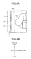
- FIG. 4A is an enlarged view of an H-portion indicated in FIG. 2 ;
- FIG. 4B is a diagram for explaining a torque control performed by a control device.
- FIG. 5 is a diagram illustrating an example of layout changes of the production apparatuses.
- FIG. 1 is a schematic outline view of a production apparatus according to the present embodiment.
- a production apparatus 1 houses a robot 12 (see FIG. 2 ) inside a cell 11 of a rectangular solid shape.
- Robot 12 can apply a general standard types of products.
- the cell 11 includes a rectangular-shaped frame 111 provided with casters (or wheels) 111a and stoppers 111b on the undersurface thereof, and outer wall portions 112a to 112d on the respective sides of the frame 111.
- the robot 12 is housed in a space formed by the frame 111 and the outer wall portions 112a to 112d.
- the production apparatus 1 has the robot 12 and the outer wall portions 112a to 112d on the frame 111 having the casters 111a. Accordingly, an operator and such can easily move the production apparatus 1 to an intended location.
- the production apparatus 1 can be fixed at a desired position.
- the production apparatus 1 can be in an operational state only by connecting a plug 113 for power supply to an external power source. As a consequence, an operator and such can make a change in layout of the production apparatus 1 in a production plant and such more easily.
- openings 114 for taking a workpiece in and out, a monitor 115 to check a working status of the robot 12, various types of instruments 116, switches (not depicted), and the like are disposed in a centralized arrangement. Accordingly, an operator and such can operate the production apparatus 1 only on the front side of the cell 11.
- a window portion 117 is provided on a part of each of the outer wall portions 112a to 112d and thus, an operator and such can see the inside of the cell 11 through the window portions 117.
- the window portions 117 are formed of polycarbonate that is transparent and is of superior impact resistance. This point will be discussed later with reference to FIGS. 4A and 4B .
- a cell is generally designed to be wide enough to contain the movable range of a robot (a maximum range in which the robot can move) to reliably prevent contact of the robot in operation with human beings.
- the range of movement of the robot in operation (hereinafter, referred to as an operating range) is slight, as compared with the movable range of the robot unless the robot is made to order according to demand. In such a case, it can be said that the space inside the cell is uselessly wide with respect to the operating range of the robot.
- the production apparatus 1 is provided with the outer wall portions 112a to 112d of the cell 11 within the movable range of the robot 12 so as to achieve downsizing of the production apparatus 1.
- merely narrowing down the space in the cell increases a possibility of the robot 12 contacting the cell 11 when, for example, an abnormal action or something of the robot 12 occurs.
- measures to improve safety of the production apparatus 1 are additionally carried out. In the followings, these points will be explained specifically.
- a depth direction when the production apparatus 1 is viewed from the front is defined as an X direction (Short-side direction of rectangular frame 111).
- a direction horizontal to a mounting surface of the production apparatus 1 is defined as a Y direction (Short-side direction of rectangular frame 111), and a direction vertical thereto is defined as a Z direction.
- FIG. 2 is a schematic top view of the production apparatus 1 according to the present embodiment.
- the production apparatus 1 houses the robot 12, a workbench 13, and the like inside the cell 11.
- the cell 11 is formed into a size slightly larger than the external form of the robot 12.
- the respective outer wall portions 112a to 112d of the cell 11 are set up so as to cover a range narrower than the movable range of the robot 12 but wider than the operating range of the robot 12.
- the cell 11 being provided within the movable range of the robot 12 in this manner allows the downsizing of the production apparatus 1.
- the robot 12 is a so-called dual-arm robot in which a right arm 122a and a left arm 122b are attached to trunk portion 121.
- the robot 12 is disposed near the outer wall portion 112b in a state of its back side facing the outer wall portion 112b.
- the right arm 122a and the left arm 122b are each a multi-axis robot (for example, a seven-axis robot), and at the distal end thereof, an end effector appropriate for work is provided.
- the robot 12 is assumed to carry out work of griping a workpiece A with the right arm 122a and a workpiece B with the left arm 122b, and then press-fitting the workpiece A to the workpiece B.
- the work that the robot 12 carries out is not limited to this.
- the robot 12 may be further configured to carry out work for a workpiece in cooperation with a work device (not depicted) provided within the cell 11.
- the trunk portion 121 of the robot 12 is connected with a base portion 124 via an actuator 123, and rotates centering around a rotation axis A1 of the actuator 123.
- the robot 12 here is designed such that the rotation axis A1 of the actuator 123 and attaching positions A2 of the right arm 122a and the left arm 122b with respect to the trunk portion 121 (pivots of the right arm 122a and the left arm 122b) are separated from each other by the amount of D1 in the X direction. In other words, the robot 12 is in a state that the trunk portion 121 is protruded forward with respect to the base portion 124 (a forward bent posture).
- the workbench 13 is then arranged in a space formed by such forward bent posture below the trunk portion 121 of the robot 12 (a bosom portion of the robot 12), and the robot 12 carries out the work on the workpieces above the workbench 13, i.e., at the bosom portion near the base portion 124.
- the robot 12 By tilting the trunk portion 121 of the robot 12 forward and arranging the workbench 13 below the trunk portion 121, the robot 12 can carry out the work at a position closer to the base portion 124. Accordingly, a clearance between the base portion 124 and the workbench 13 can be reduced and thus, the breadth of the cell 11 in the X direction can be made narrower. As a consequence, a further downsizing of the production apparatus 1 can be achieved.
- the base portion 124 of the robot 12 further includes a connector 124a to which a wiring cable 200 from a later-described control device and the like is connected.
- the connector 124a is provided in a direction facing other than the outer wall portion 112b on the back side of the cell 11, and is provided on the right arm 122a side here.
- the breadth of the cell 11 in the X direction can be made even narrower, allowing the production apparatus 1 to be further downsized.
- the connector 124a is provided on the right arm 122a side in FIG. 2
- the connector 124a may be provided on the left arm 122b side, or may be provided on the front side of the robot 12.
- the robot 12 is originally a type of robot that is provided with the connector 124a on the back side of the robot 12. Therefore, the robot 12 is housed in the cell 11 in a state where the trunk portion 121 is rotated by 90 degrees with respect to the base portion 124.
- the robot may be a type of robot with its connector being provided originally in a direction facing other than the back side.
- the robot 12 is a so-called general-purpose robot. That is, the robot 12 can be mounted in an appropriate position, and the movable range of the actuator 123 is set with the X direction (facing the front) as a center.
- the movable range of the actuator 123 of the robot 12 is set to ⁇ 180 degrees with the X direction as 0 degree.
- the robot takes posture with the actuator 123 being rotated by about 90 degrees, and the position of the connector is set nearly parallel to the Y direction.
- the robot can be suitably used even in an application where the robot is not mounted in the cell 11, and by housing the robot in the cell 11 as in the present embodiment, a more compact cell can be configured.
- FIG. 3 is a schematic side view of the production apparatus 1 according to the present embodiment.
- the shape of the cell 11 is depicted in a simplified manner.
- control device 14 that controls the whole production apparatus 1 including the robot 12 is also housed inside the cell 11.
- the control device 14 carries out, for example, controls to move the robot 12 in accordance with work information registered in advance, controls motion of the end effectors, and such.
- the control device 14 is disposed in a dead space formed below the workbench 13.
- the workbench 13 is normally placed at a relatively high position from the mounting surface so that an operator and such can take a workpiece in and out easily. As a consequence, a dead space is formed below the workbench 13.
- control device 14 is disposed under the workbench 13 so as to make efficient use of the dead space formed below the workbench 13. Consequently, a further downsizing of the production apparatus 1 can be achieved.
- the production apparatus 1 further includes a mounting rack 15 on which the instruments 116 and the like are placed in the upper part of the cell 11. That is, the mounting rack 15 is provided in a dead space formed above the robot 12 so as to make efficient use of the dead space. Consequently, a further downsizing of the production apparatus 1 can be achieved.
- an adjustment stand 125 is also provided to adjust the height of the robot 12 corresponding to the height of the workbench 13.
- the adjustment stand 125 is a member in a nearly cylindrical shape having flange portions at both ends, and the flange portion on one end is fixed to a floor surface of the cell 11 (i.e., the frame 111) and the flange portion on the other end is fixed to the base portion 124 of the robot 12.
- FIG. 4A is an enlarged view of an H-portion indicated in FIG. 2 .
- FIG. 4B is a diagram for explaining a torque control performed by the control device 14.
- a virtual wall 300 is set up on an inner side of the outer wall portions 112a to 112d.
- the virtual wall 300 is a hypothetical wall to restrict the movement of the robot 12 and is set by the control device 14.
- control device 14 controls the robot 12 not to operate beyond the virtual wall 300. Accordingly, because the operation of the robot 12 is restricted not to go beyond the virtual wall 300 even when, for example, an abnormal action or something occurs, the robot 12 can be prevented from contacting the outer wall portions 112a to 112d. While only the virtual wall 300 near the outer wall portion 112c is illustrated in FIG. 4A , the virtual wall 300 is set so as to surround the periphery of the robot 12.
- setting the virtual wall 300 and restricting the movable range of the robot 12 to an inner side of the outer wall portions 112a to 112d can reduce the possibility of the robot 12 contacting the outer wall portions 112a to 112d.
- the safety of the production apparatus 1 can be improved, and the breakage of the outer wall portions 112a to 112d and the robot 12 can also be prevented.
- the control device 14 further carries out a process of limiting the working torque of the robot 12 to below a given threshold value. For example, as illustrated in FIG. 4B , the control device 14 limits the working torque of the robot 12 to below 50 percent of a maximum torque. Accordingly, even in the event that the robot 12 should happen to contact the outer wall portions 112a to 112d, the impact that the outer wall portions 112a to 112d or the robot 12 receives can be eased as compared with an occasion where the working torque is not limited.
- the window portions 117 provided on the outer wall portions 112a to 112d are formed of polycarbonate of superior impact resistance. Consequently, even in the event that the robot 12 should happen to contact the window portion 117, the window portion 117 is hard to break and a possibility of injury of an operator and such due to broken pieces flying around like glass is low.
- the virtual wall 300 is set up on an inner side of the outer wall portions 112a to 112d, the working torque of the robot 12 is limited, and the window portions 117 are formed of polycarbonate of superior impact resistance. Consequently, even when the production apparatus 1 is downsized, the safety can be assured.
- the window portions 117 may be of high-impact resin other than polycarbonate.
- high-impact resin other than polycarbonate includes acrylate resin (polymethacrylic acid ester resin), ABS resin, and high-impact polystyrene (HIPS).
- FIG. 5 is a diagram illustrating an example of layout changes of the production apparatuses 1.
- the production apparatus 1 here has the openings 114, the monitor 115, the instruments 116, and such being disposed on the front side of the cell 11 in a centralized arrangement.
- the production apparatuses 1 can be lined side-by-side with no space between them when the production apparatuses 1 are disposed in a row.
- a space in the production plant and such can be used effectively.
- the production apparatus 1 When changing the layout of the production apparatus 1, an operator and such, after taking out the plug 113 from the external power source and releasing the stoppers 111b of the frame 111, moves the production apparatus 1 to a desired location. At that time, as explained above with reference to FIG. 1 and such, the production apparatus 1 has the frame 111 provided with the casters 111a, whereby the operator and such can move the production apparatus 1 easily.
- the production apparatus 1 is designed compact in size compared with conventional apparatuses, the operator and such can move the production apparatus 1 more easily.
- FIG. 5 three production apparatuses 1 disposed side-by-side in a row are rearranged in a U-shape.
- the production apparatus 1 includes the robot 12 and the outer wall portions 112a to 112d surrounding the robot 12 from its lateral sides, and the outer wall portions 112a to 112d are provided within the movable range of the robot 12. Consequently, in accordance with the present embodiment, the downsizing can be achieved.
- control device 14 carries out the process of limiting the working torque of the robot 12 to below a given threshold value and the process of restricting the operating range of the robot 12 to an inner side of the outer wall portions 112a to 112d. Consequently, the downsizing can be achieved while ensuring the safety.
- the window portions 117 on the outer wall portions 112a to 112d are formed of high-impact resin, whereby the safety of the production apparatus 1 can be further improved.
- the downsizing of the production apparatus 1 can be achieved even when only a part of the outer wall portions 112a to 112d is provided within the movable range of the robot 12.
- the outer wall portions 112a to 112d and the robot 12 are mounted on the frame 111 having the casters 111a.
- the art is not limited as such and, for example, for a stationary production apparatus that is not necessary to move, the apparatus may not need to include the frame 111.
- the shape of the cell 11 is not limited to this and the cell 11 may be of a cubic shape or of a cylindrical shape.
- control device 14 carries out both the process of limiting the working torque of the robot 12 to below a given threshold value and the process of restricting the operating range of the robot 12 to an inner side of the outer wall portions 112a to 112d in the above-described embodiment, the control device 14 may be configured to carry out only one of these processes.
- the robot 12 housed inside the cell 11 is a so-called dual-arm robot in the above-described embodiment, the art is not limited as such and the robot may be a single-arm robot.
- the frame 111 may be formed of high rigidity metal such as stainless and titanium to make it hard to cause a positional shift of the robot 12. Furthermore, the robot 12 may be provided with an inclinometer to make the control device 14 correct the motion of the robot 12 in response to the measuring result of the inclinometer.
Landscapes
- Engineering & Computer Science (AREA)
- Robotics (AREA)
- Mechanical Engineering (AREA)
- Manipulator (AREA)
- Multi-Process Working Machines And Systems (AREA)
Abstract
Description
- The embodiment discussed herein is directed to a production apparatus.
- In recent years, in production plants and such, to respond to rapid changes in the market, a transition from mass production methods such as a line production system to high-mix low-volume production such as a cell production system has been progressed. A cell production system here is a production system where one or more people perform work on a workpiece in a work area called a cell.
- Furthermore, production apparatuses in which a robot automatically performs the above-described cell production in place of human beings have been in development recently. For example, Japanese Patent Application Laid-open No.
2006-026777 - However, there is a room for improvement in terms of downsizing of conventional production apparatuses.
- For example, in a conventional production apparatus, a cell is generally designed to be wide enough to contain the movable range of a robot so as to reliably prevent contact of the robot in operation with human beings. Therefore, the size of the production apparatus is not sufficiently downsized.
- One aspect of an embodiment is aimed to provide a production apparatus that can achieve downsizing.
- A production apparatus according to an embodiment includes a robot and outer wall portions. The outer wall portions surround the robot from its lateral sides. Furthermore, at least a part of the outer wall portions is provided within the movable range of the robot.
- One aspect of the embodiment provides a production apparatus that can achieve downsizing.
- A more complete appreciation of the invention and many of the attendant advantages thereof will be readily obtained as the same becomes better understood by reference to the following detailed description when considered in connection with the accompanying drawings, wherein:
-
FIG. 1 is a schematic outline view of a production apparatus according to an embodiment; -
FIG. 2 is a schematic top view of the production apparatus according to the embodiment; -
FIG. 3 is a schematic side view of the production apparatus according to the embodiment; -
FIG. 4A is an enlarged view of an H-portion indicated inFIG. 2 ; -
FIG. 4B is a diagram for explaining a torque control performed by a control device; and -
FIG. 5 is a diagram illustrating an example of layout changes of the production apparatuses. - With reference to the accompanying drawings, an embodiment of a production apparatus disclosed in the present application will be described in detail hereinafter. However, the invention is not intended to be restricted by the following embodiment described.
-
FIG. 1 is a schematic outline view of a production apparatus according to the present embodiment. As illustrated inFIG. 1 , aproduction apparatus 1 according to the embodiment houses a robot 12 (seeFIG. 2 ) inside acell 11 of a rectangular solid shape. Robot 12 can apply a general standard types of products. - More specifically, the
cell 11 includes a rectangular-shaped frame 111 provided with casters (or wheels) 111a andstoppers 111b on the undersurface thereof, andouter wall portions 112a to 112d on the respective sides of theframe 111. Therobot 12 is housed in a space formed by theframe 111 and theouter wall portions 112a to 112d. - The
production apparatus 1 has therobot 12 and theouter wall portions 112a to 112d on theframe 111 having thecasters 111a. Accordingly, an operator and such can easily move theproduction apparatus 1 to an intended location. - Consequently, for example, a layout change of the
production apparatus 1 in a production plant and such can be made easily. Because thestoppers 111b are further provided on the undersurface of theframe 111, theproduction apparatus 1 can be fixed at a desired position. - In the
cell 11, other than therobot 12, all of the various devices necessary for the operation of theproduction apparatus 1 are housed and thus, theproduction apparatus 1 can be in an operational state only by connecting aplug 113 for power supply to an external power source. As a consequence, an operator and such can make a change in layout of theproduction apparatus 1 in a production plant and such more easily. - On the
outer wall portion 112a of the front side of thecell 11,openings 114 for taking a workpiece in and out, amonitor 115 to check a working status of therobot 12, various types ofinstruments 116, switches (not depicted), and the like are disposed in a centralized arrangement. Accordingly, an operator and such can operate theproduction apparatus 1 only on the front side of thecell 11. - Furthermore, on a part of each of the
outer wall portions 112a to 112d, awindow portion 117 is provided and thus, an operator and such can see the inside of thecell 11 through thewindow portions 117. In the present embodiment, thewindow portions 117 are formed of polycarbonate that is transparent and is of superior impact resistance. This point will be discussed later with reference toFIGS. 4A and 4B . - Meanwhile, a cell is generally designed to be wide enough to contain the movable range of a robot (a maximum range in which the robot can move) to reliably prevent contact of the robot in operation with human beings.
- However, in some operations, the range of movement of the robot in operation (hereinafter, referred to as an operating range) is slight, as compared with the movable range of the robot unless the robot is made to order according to demand. In such a case, it can be said that the space inside the cell is uselessly wide with respect to the operating range of the robot.
- Accordingly, when the space in the cell of a production apparatus is uselessly wide, in other words, when the size of the apparatus is uselessly large, it is possible that a useless space is taken up in a production plant and such and, furthermore, a lot of effort is needed for the above-described change in layout or the like.
- Therefore, the
production apparatus 1 according to the present embodiment is provided with theouter wall portions 112a to 112d of thecell 11 within the movable range of therobot 12 so as to achieve downsizing of theproduction apparatus 1. However, merely narrowing down the space in the cell increases a possibility of therobot 12 contacting thecell 11 when, for example, an abnormal action or something of therobot 12 occurs. For this reason, in the present embodiment, measures to improve safety of theproduction apparatus 1 are additionally carried out. In the followings, these points will be explained specifically. - In the followings, a depth direction when the
production apparatus 1 is viewed from the front is defined as an X direction (Short-side direction of rectangular frame 111). A direction horizontal to a mounting surface of theproduction apparatus 1 is defined as a Y direction (Short-side direction of rectangular frame 111), and a direction vertical thereto is defined as a Z direction. -
FIG. 2 is a schematic top view of theproduction apparatus 1 according to the present embodiment. As illustrated inFIG. 2 , theproduction apparatus 1 houses therobot 12, aworkbench 13, and the like inside thecell 11. As depicted inFIG. 2 , thecell 11 is formed into a size slightly larger than the external form of therobot 12. Specifically, the respectiveouter wall portions 112a to 112d of thecell 11 are set up so as to cover a range narrower than the movable range of therobot 12 but wider than the operating range of therobot 12. Thecell 11 being provided within the movable range of therobot 12 in this manner allows the downsizing of theproduction apparatus 1. - The
robot 12 is a so-called dual-arm robot in which aright arm 122a and aleft arm 122b are attached totrunk portion 121. Therobot 12 is disposed near theouter wall portion 112b in a state of its back side facing theouter wall portion 112b. Theright arm 122a and theleft arm 122b are each a multi-axis robot (for example, a seven-axis robot), and at the distal end thereof, an end effector appropriate for work is provided. - In the present embodiment, the
robot 12 is assumed to carry out work of griping a workpiece A with theright arm 122a and a workpiece B with theleft arm 122b, and then press-fitting the workpiece A to the workpiece B. However, the work that therobot 12 carries out is not limited to this. Therobot 12 may be further configured to carry out work for a workpiece in cooperation with a work device (not depicted) provided within thecell 11. - The
trunk portion 121 of therobot 12 is connected with abase portion 124 via anactuator 123, and rotates centering around a rotation axis A1 of theactuator 123. - The
robot 12 here is designed such that the rotation axis A1 of theactuator 123 and attaching positions A2 of theright arm 122a and theleft arm 122b with respect to the trunk portion 121 (pivots of theright arm 122a and theleft arm 122b) are separated from each other by the amount of D1 in the X direction. In other words, therobot 12 is in a state that thetrunk portion 121 is protruded forward with respect to the base portion 124 (a forward bent posture). - With the
robot 12 having a forward bent posture in this way, it is possible to move theright arm 122a and theleft arm 122b to positions even closer to thebase portion 124 as compared with therobot 12 having a standing posture (where A1 and A2 are matched). - The
workbench 13 is then arranged in a space formed by such forward bent posture below thetrunk portion 121 of the robot 12 (a bosom portion of the robot 12), and therobot 12 carries out the work on the workpieces above theworkbench 13, i.e., at the bosom portion near thebase portion 124. - By tilting the
trunk portion 121 of therobot 12 forward and arranging theworkbench 13 below thetrunk portion 121, therobot 12 can carry out the work at a position closer to thebase portion 124. Accordingly, a clearance between thebase portion 124 and theworkbench 13 can be reduced and thus, the breadth of thecell 11 in the X direction can be made narrower. As a consequence, a further downsizing of theproduction apparatus 1 can be achieved. - The
base portion 124 of therobot 12 further includes aconnector 124a to which awiring cable 200 from a later-described control device and the like is connected. Theconnector 124a is provided in a direction facing other than theouter wall portion 112b on the back side of thecell 11, and is provided on theright arm 122a side here. - By providing the
connector 124a in a direction facing other than theouter wall portion 112b on the back side of therobot 12, it becomes unnecessary, as indicated by dashed lines inFIG. 2 , to secure a space to arrange thewiring cable 200 between therobot 12 and theouter wall portion 112b on the back side of therobot 12. - Consequently, the breadth of the
cell 11 in the X direction can be made even narrower, allowing theproduction apparatus 1 to be further downsized. - While the
connector 124a is provided on theright arm 122a side inFIG. 2 , theconnector 124a may be provided on theleft arm 122b side, or may be provided on the front side of therobot 12. - Meanwhile, the
robot 12 according to the present embodiment is originally a type of robot that is provided with theconnector 124a on the back side of therobot 12. Therefore, therobot 12 is housed in thecell 11 in a state where thetrunk portion 121 is rotated by 90 degrees with respect to thebase portion 124. However, the robot may be a type of robot with its connector being provided originally in a direction facing other than the back side. - The
robot 12 according to the present embodiment is a so-called general-purpose robot. That is, therobot 12 can be mounted in an appropriate position, and the movable range of theactuator 123 is set with the X direction (facing the front) as a center. - For example, the movable range of the
actuator 123 of therobot 12 is set to ±180 degrees with the X direction as 0 degree. When mounting therobot 12 to thecell 11, the robot takes posture with theactuator 123 being rotated by about 90 degrees, and the position of the connector is set nearly parallel to the Y direction. - Accordingly, the robot can be suitably used even in an application where the robot is not mounted in the
cell 11, and by housing the robot in thecell 11 as in the present embodiment, a more compact cell can be configured. - An internal configuration of the
production apparatus 1 will be further explained with reference toFIG. 3. FIG. 3 is a schematic side view of theproduction apparatus 1 according to the present embodiment. InFIG. 3 , to make the internal configuration of thecell 11 easier to understand, the shape of thecell 11 is depicted in a simplified manner. - As illustrated in
FIG. 3 , other than therobot 12 and theworkbench 13, acontrol device 14 that controls thewhole production apparatus 1 including therobot 12 is also housed inside thecell 11. Thecontrol device 14 carries out, for example, controls to move therobot 12 in accordance with work information registered in advance, controls motion of the end effectors, and such. - The
control device 14 is disposed in a dead space formed below theworkbench 13. Specifically, theworkbench 13 is normally placed at a relatively high position from the mounting surface so that an operator and such can take a workpiece in and out easily. As a consequence, a dead space is formed below theworkbench 13. - Therefore, in the
production apparatus 1, thecontrol device 14 is disposed under theworkbench 13 so as to make efficient use of the dead space formed below theworkbench 13. Consequently, a further downsizing of theproduction apparatus 1 can be achieved. - The
production apparatus 1 further includes a mountingrack 15 on which theinstruments 116 and the like are placed in the upper part of thecell 11. That is, the mountingrack 15 is provided in a dead space formed above therobot 12 so as to make efficient use of the dead space. Consequently, a further downsizing of theproduction apparatus 1 can be achieved. - In the
cell 11, anadjustment stand 125 is also provided to adjust the height of therobot 12 corresponding to the height of theworkbench 13. The adjustment stand 125 is a member in a nearly cylindrical shape having flange portions at both ends, and the flange portion on one end is fixed to a floor surface of the cell 11 (i.e., the frame 111) and the flange portion on the other end is fixed to thebase portion 124 of therobot 12. - Next, a configuration to improve safety of the
production apparatus 1 will be described with reference toFIGS. 4A and 4B. FIG. 4A is an enlarged view of an H-portion indicated inFIG. 2 .FIG. 4B is a diagram for explaining a torque control performed by thecontrol device 14. - As illustrated in
FIG. 4A , in theproduction apparatus 1, avirtual wall 300 is set up on an inner side of theouter wall portions 112a to 112d. Thevirtual wall 300 is a hypothetical wall to restrict the movement of therobot 12 and is set by thecontrol device 14. - More specifically, the
control device 14 controls therobot 12 not to operate beyond thevirtual wall 300. Accordingly, because the operation of therobot 12 is restricted not to go beyond thevirtual wall 300 even when, for example, an abnormal action or something occurs, therobot 12 can be prevented from contacting theouter wall portions 112a to 112d. While only thevirtual wall 300 near theouter wall portion 112c is illustrated inFIG. 4A , thevirtual wall 300 is set so as to surround the periphery of therobot 12. - Accordingly, setting the
virtual wall 300 and restricting the movable range of therobot 12 to an inner side of theouter wall portions 112a to 112d can reduce the possibility of therobot 12 contacting theouter wall portions 112a to 112d. As a consequence, the safety of theproduction apparatus 1 can be improved, and the breakage of theouter wall portions 112a to 112d and therobot 12 can also be prevented. - The
control device 14 further carries out a process of limiting the working torque of therobot 12 to below a given threshold value. For example, as illustrated inFIG. 4B , thecontrol device 14 limits the working torque of therobot 12 to below 50 percent of a maximum torque. Accordingly, even in the event that therobot 12 should happen to contact theouter wall portions 112a to 112d, the impact that theouter wall portions 112a to 112d or therobot 12 receives can be eased as compared with an occasion where the working torque is not limited. - Furthermore, the
window portions 117 provided on theouter wall portions 112a to 112d are formed of polycarbonate of superior impact resistance. Consequently, even in the event that therobot 12 should happen to contact thewindow portion 117, thewindow portion 117 is hard to break and a possibility of injury of an operator and such due to broken pieces flying around like glass is low. - As described in the foregoing, in the present embodiment, the
virtual wall 300 is set up on an inner side of theouter wall portions 112a to 112d, the working torque of therobot 12 is limited, and thewindow portions 117 are formed of polycarbonate of superior impact resistance. Consequently, even when theproduction apparatus 1 is downsized, the safety can be assured. - While the
window portions 117 here are formed using polycarbonate of outstanding impact resistance, thewindow portions 117 may be of high-impact resin other than polycarbonate. For example, high-impact resin other than polycarbonate includes acrylate resin (polymethacrylic acid ester resin), ABS resin, and high-impact polystyrene (HIPS). - Next, layout changes of the
production apparatuses 1 will be described with reference toFIG. 5. FIG. 5 is a diagram illustrating an example of layout changes of theproduction apparatuses 1. - As illustrated in
FIG. 5 , it is assumed that, in a production plant and such, a plurality of theproduction apparatuses 1 are lined side-by-side in a row. As explained above with reference toFIG. 1 , theproduction apparatus 1 here has theopenings 114, themonitor 115, theinstruments 116, and such being disposed on the front side of thecell 11 in a centralized arrangement. - In other words, because there are no instruments, switches, or the like provided on the side surfaces of the
production apparatus 1, theproduction apparatuses 1 can be lined side-by-side with no space between them when theproduction apparatuses 1 are disposed in a row. Thus, a space in the production plant and such can be used effectively. - When changing the layout of the
production apparatus 1, an operator and such, after taking out theplug 113 from the external power source and releasing thestoppers 111b of theframe 111, moves theproduction apparatus 1 to a desired location. At that time, as explained above with reference toFIG. 1 and such, theproduction apparatus 1 has theframe 111 provided with thecasters 111a, whereby the operator and such can move theproduction apparatus 1 easily. - Furthermore, because the
production apparatus 1 is designed compact in size compared with conventional apparatuses, the operator and such can move theproduction apparatus 1 more easily. InFIG. 5 , threeproduction apparatuses 1 disposed side-by-side in a row are rearranged in a U-shape. - As described above in the foregoing, in the present embodiment, the
production apparatus 1 includes therobot 12 and theouter wall portions 112a to 112d surrounding therobot 12 from its lateral sides, and theouter wall portions 112a to 112d are provided within the movable range of therobot 12. Consequently, in accordance with the present embodiment, the downsizing can be achieved. - Furthermore, in the present embodiment, the
control device 14 carries out the process of limiting the working torque of therobot 12 to below a given threshold value and the process of restricting the operating range of therobot 12 to an inner side of theouter wall portions 112a to 112d. Consequently, the downsizing can be achieved while ensuring the safety. - Moreover, in the above-described embodiment, the
window portions 117 on theouter wall portions 112a to 112d are formed of high-impact resin, whereby the safety of theproduction apparatus 1 can be further improved. - While all of the
outer wall portions 112a to 112d are provided within the movable range of therobot 12 in the above-described embodiment, the downsizing of theproduction apparatus 1 can be achieved even when only a part of theouter wall portions 112a to 112d is provided within the movable range of therobot 12. - In the above-described embodiment, to make the
production apparatus 1 easy to move, theouter wall portions 112a to 112d and therobot 12 are mounted on theframe 111 having thecasters 111a. However, the art is not limited as such and, for example, for a stationary production apparatus that is not necessary to move, the apparatus may not need to include theframe 111. - While the cell is of a rectangular solid shape in the above-described embodiment, the shape of the
cell 11 is not limited to this and thecell 11 may be of a cubic shape or of a cylindrical shape. - While the
control device 14 carries out both the process of limiting the working torque of therobot 12 to below a given threshold value and the process of restricting the operating range of therobot 12 to an inner side of theouter wall portions 112a to 112d in the above-described embodiment, thecontrol device 14 may be configured to carry out only one of these processes. - While the
robot 12 housed inside thecell 11 is a so-called dual-arm robot in the above-described embodiment, the art is not limited as such and the robot may be a single-arm robot. - Meanwhile, the above-described embodiment has been described on the assumption that the positional relation between the
robot 12 and theworkbench 13 is unchanged. However, for example, when deflection is caused to theframe 111, the positional relation between therobot 12 and theworkbench 13 is changed, and thus it is conceivable that the work on the workpieces may not be performed properly. - Therefore, in the
production apparatus 1, theframe 111 may be formed of high rigidity metal such as stainless and titanium to make it hard to cause a positional shift of therobot 12. Furthermore, therobot 12 may be provided with an inclinometer to make thecontrol device 14 correct the motion of therobot 12 in response to the measuring result of the inclinometer.
Claims (7)
- A production apparatus (1) comprising:a robot (12); andouter walls (112a to 112d) surrounding the robot (12) from lateral sides thereof, whereinat least a part of the outer walls (112a to 112d) is provided within a movable range of the robot (12).
- The production apparatus (1) according to claim 1, wherein the outer walls (112a to 112d) within the movable range include members of high-impact resin.
- The production apparatus (1) according to claim 1 or 2, further comprising a controller (14) that carries out either one of or both of a process of limiting a working torque of the robot (12) to below a given threshold value and a process of restricting the an operating range of the robot (12) to an inner side of the outer walls (112a to 112d).
- The production apparatus (1) according to any one of claims 1 to 3, wherein the robot (12) and the outer walls (112a to 112d) are mounted on a rectangular-shaped frame provided with casters (111a).
- The production apparatus (1) according to claim 4, whereinthe robot (12) is a dual-arm robot and is disposed near the outer wall (112b) provided on one side of the rectangular-shaped frame with a back side of the robot (12) facing the outer wall (112b), anda connector (124a) of the robot (12) is provided in a direction facing other than the back side of the robot (12).
- The production apparatus (1) according to claim 5, whereinthe robot (12) comprises a forward bent trunk portion (121), andthe production apparatus (1) comprises a workbench (13) disposed under the trunk portion (121).
- The production apparatus (1) according to claim 6, wherein the controller (14) is disposed under the workbench (13).
Applications Claiming Priority (1)
| Application Number | Priority Date | Filing Date | Title |
|---|---|---|---|
| JP2011053014A JP5370395B2 (en) | 2011-03-10 | 2011-03-10 | Production equipment |
Publications (1)
| Publication Number | Publication Date |
|---|---|
| EP2497613A1 true EP2497613A1 (en) | 2012-09-12 |
Family
ID=45540821
Family Applications (1)
| Application Number | Title | Priority Date | Filing Date |
|---|---|---|---|
| EP12152783A Withdrawn EP2497613A1 (en) | 2011-03-10 | 2012-01-27 | Robot surrounded by outer walls |
Country Status (4)
| Country | Link |
|---|---|
| US (1) | US20120232698A1 (en) |
| EP (1) | EP2497613A1 (en) |
| JP (1) | JP5370395B2 (en) |
| CN (1) | CN102672547B (en) |
Cited By (2)
| Publication number | Priority date | Publication date | Assignee | Title |
|---|---|---|---|---|
| WO2016074710A1 (en) * | 2014-11-12 | 2016-05-19 | Abb Technology Ltd | A compact robot system |
| CN109129459A (en) * | 2017-06-28 | 2019-01-04 | 上海优爱宝智能机器人科技股份有限公司 | Tow-armed robot |
Families Citing this family (14)
| Publication number | Priority date | Publication date | Assignee | Title |
|---|---|---|---|---|
| JP4770856B2 (en) * | 2008-03-21 | 2011-09-14 | トヨタ自動車株式会社 | Transfer robot |
| US8661928B1 (en) * | 2008-06-20 | 2014-03-04 | Wowwee Group Limited | Method and system for articulating the upper limbs of a humanoid |
| KR101572852B1 (en) * | 2010-01-06 | 2015-12-01 | 삼성전자 주식회사 | Compact exoskeleton arm support device for gravity compensation |
| JP5978588B2 (en) * | 2011-10-14 | 2016-08-24 | セイコーエプソン株式会社 | Double arm robot |
| WO2014054183A1 (en) * | 2012-10-05 | 2014-04-10 | 株式会社安川電機 | Automatic preparation system |
| JP2014124737A (en) * | 2012-12-27 | 2014-07-07 | Seiko Epson Corp | Robot, and robot system |
| JP2015031407A (en) * | 2013-07-31 | 2015-02-16 | 株式会社安川電機 | Working cabinet and sheet material |
| EP3290168A4 (en) | 2015-04-28 | 2018-12-12 | Seiko Epson Corporation | Robot system and robot |
| WO2017085897A1 (en) * | 2015-11-16 | 2017-05-26 | 川崎重工業株式会社 | Manufacturing system, construction method of manufacturing system, end effector, robot, and robot operating method |
| JP7001352B2 (en) * | 2017-03-06 | 2022-01-19 | 川崎重工業株式会社 | robot |
| CN109015644A (en) * | 2018-08-17 | 2018-12-18 | 徐润秋 | A kind of robot security's operation control method |
| CN109571553A (en) * | 2018-11-06 | 2019-04-05 | 长沙米淇仪器设备有限公司 | A kind of robot manipulation's case |
| CN109866210B (en) * | 2019-03-28 | 2021-12-17 | 合肥工业大学 | Double-arm six-degree-of-freedom robot easy to assemble |
| CN114131606B (en) * | 2021-12-07 | 2024-05-10 | 亿嘉和科技股份有限公司 | Task scheduling method for double-arm inspection robot |
Citations (5)
| Publication number | Priority date | Publication date | Assignee | Title |
|---|---|---|---|---|
| JP2006026777A (en) | 2004-07-14 | 2006-02-02 | Toyota Motor Corp | Work unit and production line |
| US20060043111A1 (en) * | 2004-08-23 | 2006-03-02 | Craig Jennings | Robotic beverage server |
| DE102004051753A1 (en) * | 2004-10-23 | 2006-04-27 | Robert Bosch Gmbh | Protection chamber for assembling mechanism, has seal arranged between panels and recesses on side of housing and enabling housing to take energy utilized by robot arm during operational interferences on housing |
| JP2010162666A (en) * | 2009-01-19 | 2010-07-29 | Yaskawa Electric Corp | Multi-joint robot and robot system using the same |
| DE202010015780U1 (en) * | 2010-11-23 | 2011-03-03 | Goldfuss, Thomas | Flexible robot cell |
Family Cites Families (19)
| Publication number | Priority date | Publication date | Assignee | Title |
|---|---|---|---|---|
| JPS6044293A (en) * | 1983-08-18 | 1985-03-09 | 株式会社日立製作所 | Control system of industrial robot |
| JPH0596487A (en) * | 1991-10-03 | 1993-04-20 | Matsushita Electric Ind Co Ltd | Industrial robot |
| JPH0911179A (en) * | 1995-06-27 | 1997-01-14 | Shibaura Eng Works Co Ltd | Industrial robot |
| JP3286842B2 (en) * | 1995-12-23 | 2002-05-27 | 株式会社安川電機 | Flexible control device for robot |
| US20040243147A1 (en) * | 2001-07-03 | 2004-12-02 | Lipow Kenneth I. | Surgical robot and robotic controller |
| JP2003019688A (en) * | 2001-07-10 | 2003-01-21 | Shinba Iron Works Inc | Robot safety device |
| JP3975959B2 (en) * | 2003-04-23 | 2007-09-12 | トヨタ自動車株式会社 | Robot operation regulating method and apparatus, and robot equipped with the same |
| US20060037969A1 (en) * | 2004-08-23 | 2006-02-23 | Craig Jennings | Robotic beverage server |
| US7577498B2 (en) * | 2005-08-23 | 2009-08-18 | Motoman, Inc. | Apparatus and methods for a robotic beverage server |
| WO2007041295A2 (en) * | 2005-09-30 | 2007-04-12 | Irobot Corporation | Companion robot for personal interaction |
| JP2007185723A (en) * | 2006-01-11 | 2007-07-26 | Fujifilm Corp | Automatic alignment device and method |
| US7719222B2 (en) * | 2006-03-30 | 2010-05-18 | Vecna Technologies, Inc. | Mobile extraction-assist robot |
| US8560118B2 (en) * | 2007-04-16 | 2013-10-15 | Neuroarm Surgical Ltd. | Methods, devices, and systems for non-mechanically restricting and/or programming movement of a tool of a manipulator along a single axis |
| JP2010105106A (en) * | 2008-10-29 | 2010-05-13 | Olympus Corp | Production device |
| JP5237056B2 (en) * | 2008-11-10 | 2013-07-17 | 本田技研工業株式会社 | Door removal system and door removal method |
| JP5276424B2 (en) * | 2008-12-05 | 2013-08-28 | 日本電産サンキョー株式会社 | safety cover |
| CN101590323B (en) * | 2009-07-08 | 2012-10-31 | 北京工业大学 | Single-wheel robot system and control method thereof |
| US8918209B2 (en) * | 2010-05-20 | 2014-12-23 | Irobot Corporation | Mobile human interface robot |
| CN101947785A (en) * | 2010-08-30 | 2011-01-19 | 苏州博实机器人技术有限公司 | Reconfigurable in-parallel robot |
-
2011
- 2011-03-10 JP JP2011053014A patent/JP5370395B2/en active Active
-
2012
- 2012-01-23 US US13/355,564 patent/US20120232698A1/en not_active Abandoned
- 2012-01-27 EP EP12152783A patent/EP2497613A1/en not_active Withdrawn
- 2012-02-08 CN CN201210027760.2A patent/CN102672547B/en not_active Expired - Fee Related
Patent Citations (5)
| Publication number | Priority date | Publication date | Assignee | Title |
|---|---|---|---|---|
| JP2006026777A (en) | 2004-07-14 | 2006-02-02 | Toyota Motor Corp | Work unit and production line |
| US20060043111A1 (en) * | 2004-08-23 | 2006-03-02 | Craig Jennings | Robotic beverage server |
| DE102004051753A1 (en) * | 2004-10-23 | 2006-04-27 | Robert Bosch Gmbh | Protection chamber for assembling mechanism, has seal arranged between panels and recesses on side of housing and enabling housing to take energy utilized by robot arm during operational interferences on housing |
| JP2010162666A (en) * | 2009-01-19 | 2010-07-29 | Yaskawa Electric Corp | Multi-joint robot and robot system using the same |
| DE202010015780U1 (en) * | 2010-11-23 | 2011-03-03 | Goldfuss, Thomas | Flexible robot cell |
Cited By (2)
| Publication number | Priority date | Publication date | Assignee | Title |
|---|---|---|---|---|
| WO2016074710A1 (en) * | 2014-11-12 | 2016-05-19 | Abb Technology Ltd | A compact robot system |
| CN109129459A (en) * | 2017-06-28 | 2019-01-04 | 上海优爱宝智能机器人科技股份有限公司 | Tow-armed robot |
Also Published As
| Publication number | Publication date |
|---|---|
| JP2012187663A (en) | 2012-10-04 |
| CN102672547A (en) | 2012-09-19 |
| US20120232698A1 (en) | 2012-09-13 |
| JP5370395B2 (en) | 2013-12-18 |
| CN102672547B (en) | 2016-06-15 |
Similar Documents
| Publication | Publication Date | Title |
|---|---|---|
| US20120232698A1 (en) | Production apparatus | |
| CN111084661B (en) | Surgical auxiliary device, and recording medium | |
| EP3238893B1 (en) | Robot system | |
| US10611027B2 (en) | Assembly apparatus and control method therefor | |
| US11247329B2 (en) | Work device and dual-arm work device | |
| CN104552242B (en) | Robot, robot abutment | |
| US10293479B2 (en) | Robot and robot system | |
| JP6562174B1 (en) | Surgery support device | |
| CN106002931B (en) | Robot system | |
| JP6797945B2 (en) | Robots and robot assemblies for patient positioning | |
| TWI654057B (en) | Isolator system | |
| US10814477B2 (en) | Robot | |
| US20180194002A1 (en) | Composite work device using link operating device | |
| KR20190073561A (en) | Industrial Robots | |
| US20130209200A1 (en) | Carrier device | |
| CN106002933A (en) | Robot system | |
| CN117426872A (en) | System including support structure and robot positioner | |
| US20160167236A1 (en) | Tool adapter for robot wrist and robot with tool adapter attached thereto | |
| JP7542960B2 (en) | Horizontal articulated robot and substrate transfer system equipped with the same | |
| CN113056815A (en) | Manipulator and robot with same | |
| EP3127663B1 (en) | Industrial robot and frame unit thereof | |
| US11267039B2 (en) | Triaxial spring-making machine and method thereof | |
| CN117921686A (en) | Stand for robot | |
| CN218875470U (en) | Working device and collision protection structure thereof | |
| JP7396098B2 (en) | work area monitoring device |
Legal Events
| Date | Code | Title | Description |
|---|---|---|---|
| PUAI | Public reference made under article 153(3) epc to a published international application that has entered the european phase |
Free format text: ORIGINAL CODE: 0009012 |
|
| AK | Designated contracting states |
Kind code of ref document: A1 Designated state(s): AL AT BE BG CH CY CZ DE DK EE ES FI FR GB GR HR HU IE IS IT LI LT LU LV MC MK MT NL NO PL PT RO RS SE SI SK SM TR |
|
| AX | Request for extension of the european patent |
Extension state: BA ME |
|
| 17P | Request for examination filed |
Effective date: 20130225 |
|
| 17Q | First examination report despatched |
Effective date: 20140120 |
|
| GRAP | Despatch of communication of intention to grant a patent |
Free format text: ORIGINAL CODE: EPIDOSNIGR1 |
|
| INTG | Intention to grant announced |
Effective date: 20160613 |
|
| RAP1 | Party data changed (applicant data changed or rights of an application transferred) |
Owner name: KABUSHIKI KAISHA YASKAWA DENKI |
|
| STAA | Information on the status of an ep patent application or granted ep patent |
Free format text: STATUS: THE APPLICATION IS DEEMED TO BE WITHDRAWN |
|
| 18D | Application deemed to be withdrawn |
Effective date: 20161025 |