EP2496826B1 - Verfahren und system zur steuerung eines zündsystems - Google Patents
Verfahren und system zur steuerung eines zündsystems Download PDFInfo
- Publication number
- EP2496826B1 EP2496826B1 EP10828628.7A EP10828628A EP2496826B1 EP 2496826 B1 EP2496826 B1 EP 2496826B1 EP 10828628 A EP10828628 A EP 10828628A EP 2496826 B1 EP2496826 B1 EP 2496826B1
- Authority
- EP
- European Patent Office
- Prior art keywords
- coil
- flywheel
- trig
- ignition system
- magnetic flux
- Prior art date
- Legal status (The legal status is an assumption and is not a legal conclusion. Google has not performed a legal analysis and makes no representation as to the accuracy of the status listed.)
- Active
Links
Images


Classifications
-
- F—MECHANICAL ENGINEERING; LIGHTING; HEATING; WEAPONS; BLASTING
- F02—COMBUSTION ENGINES; HOT-GAS OR COMBUSTION-PRODUCT ENGINE PLANTS
- F02P—IGNITION, OTHER THAN COMPRESSION IGNITION, FOR INTERNAL-COMBUSTION ENGINES; TESTING OF IGNITION TIMING IN COMPRESSION-IGNITION ENGINES
- F02P3/00—Other installations
- F02P3/02—Other installations having inductive energy storage, e.g. arrangements of induction coils
- F02P3/04—Layout of circuits
- F02P3/0407—Opening or closing the primary coil circuit with electronic switching means
- F02P3/0414—Opening or closing the primary coil circuit with electronic switching means using digital techniques
-
- F—MECHANICAL ENGINEERING; LIGHTING; HEATING; WEAPONS; BLASTING
- F02—COMBUSTION ENGINES; HOT-GAS OR COMBUSTION-PRODUCT ENGINE PLANTS
- F02P—IGNITION, OTHER THAN COMPRESSION IGNITION, FOR INTERNAL-COMBUSTION ENGINES; TESTING OF IGNITION TIMING IN COMPRESSION-IGNITION ENGINES
- F02P1/00—Installations having electric ignition energy generated by magneto- or dynamo- electric generators without subsequent storage
- F02P1/08—Layout of circuits
- F02P1/086—Layout of circuits for generating sparks by discharging a capacitor into a coil circuit
-
- F—MECHANICAL ENGINEERING; LIGHTING; HEATING; WEAPONS; BLASTING
- F02—COMBUSTION ENGINES; HOT-GAS OR COMBUSTION-PRODUCT ENGINE PLANTS
- F02P—IGNITION, OTHER THAN COMPRESSION IGNITION, FOR INTERNAL-COMBUSTION ENGINES; TESTING OF IGNITION TIMING IN COMPRESSION-IGNITION ENGINES
- F02P17/00—Testing of ignition installations, e.g. in combination with adjusting; Testing of ignition timing in compression-ignition engines
- F02P17/12—Testing characteristics of the spark, ignition voltage or current
-
- F—MECHANICAL ENGINEERING; LIGHTING; HEATING; WEAPONS; BLASTING
- F02—COMBUSTION ENGINES; HOT-GAS OR COMBUSTION-PRODUCT ENGINE PLANTS
- F02P—IGNITION, OTHER THAN COMPRESSION IGNITION, FOR INTERNAL-COMBUSTION ENGINES; TESTING OF IGNITION TIMING IN COMPRESSION-IGNITION ENGINES
- F02P3/00—Other installations
- F02P3/06—Other installations having capacitive energy storage
- F02P3/08—Layout of circuits
- F02P3/09—Layout of circuits for control of the charging current in the capacitor
- F02P3/093—Closing the discharge circuit of the storage capacitor with semiconductor devices
- F02P3/096—Closing the discharge circuit of the storage capacitor with semiconductor devices using digital techniques
-
- H—ELECTRICITY
- H04—ELECTRIC COMMUNICATION TECHNIQUE
- H04B—TRANSMISSION
- H04B15/00—Suppression or limitation of noise or interference
- H04B15/02—Reducing interference from electric apparatus by means located at or near the interfering apparatus
-
- F—MECHANICAL ENGINEERING; LIGHTING; HEATING; WEAPONS; BLASTING
- F02—COMBUSTION ENGINES; HOT-GAS OR COMBUSTION-PRODUCT ENGINE PLANTS
- F02P—IGNITION, OTHER THAN COMPRESSION IGNITION, FOR INTERNAL-COMBUSTION ENGINES; TESTING OF IGNITION TIMING IN COMPRESSION-IGNITION ENGINES
- F02P17/00—Testing of ignition installations, e.g. in combination with adjusting; Testing of ignition timing in compression-ignition engines
- F02P2017/003—Testing of ignition installations, e.g. in combination with adjusting; Testing of ignition timing in compression-ignition engines using an inductive sensor, e.g. trigger tongs
Definitions
- the present invention relates to a method for monitoring an ignition system, wherein the ignition system comprises a charge coil and a control unit.
- the invention also relates to a control system for an ignition system.
- a problem lies in gathering information regarding the performance of the system, since any attempt at measuring properties such as the magnetic flux at the charge coil or trig coil of a conventional system will suffer from disturbances due to the spark generation, among other things.
- the charge coil is periodically short-circuited in order to enhance the charging of a charge capacitor, such as is shown by SE0600752-0, for instance, this process also generates a high level of disturbances in the magnetic flux in the ignition system. It is therefore difficult to gather enough information to successfully monitor and control the ignition system, and as a result sparks can be generated at an unsuitable position or direction, such as during high compression in the engine, for instance.
- the object of the present invention is to eliminate or at least to minimise the problems described above.
- This is achieved through a method according to the preamble of claim 1, wherein the method comprises the steps of providing a separate coil adjacent to at least one of the charge coil, primary coil or secondary coil, using the control unit to monitor a magnetic flux at the separate coil, and using information regarding said magnetic flux as input for controlling at least one property of an operation of the ignition system.
- the performance of these coils in creating or altering a magnetic flux can be monitored in a reliable manner, while decreasing the risk of measuring disturbances that can be created at a coil during some stages of operation of the ignition system.
- the generation of a current at the charge coil can be monitored, as well as the process of generating a spark at the primary and secondary coil. Since the measurement takes place on a separate coil not taking part in the charging and spark creation, the disadvantages otherwise associated with performing measurements on either of these coils or on a trig coil, namely the generation of disturbances on the magnetic field at or around an iron core used with any or all of these coils, can be avoided and the reliability of the gathered data significantly increased. It is especially beneficial to detect a direction of rotation of a flywheel through the analysis of the magnetic flux.
- the ignition system further comprises a trig coil and the method comprises the step of using information regarding a magnetic flux at the trig coil together with the information of the magnetic flux at the separate coil as input for controlling at least one property of an operation of the ignition system.
- the speed and position of a flywheel with one or more magnets can be determined, and the risk for giving off a spark at an undesirable time can be substantially lowered.
- Fig. 1 shows a circuit diagram of a conventional ignition system, modified according to a preferred embodiment of the invention.
- An iron core T1 with four conventionally arranged coils, L1, L2, L4 and L5, is arranged to be magnetised by at least one magnet, rotating with a flywheel (not shown) in the vicinity of the iron core T1.
- the first coil L1 is a charge coil, arranged for inducing a voltage that can be used for generating a spark, and for this purpose the charge coil L1 is connected at one end 2 to ground and at another end 1 to a charge capacitor C1 via a rectifier D1.
- the coils L4 and L5 are a primary and secondary coil, respectively, and are arranged to serve as a transformer and generate an ignition voltage to a spark plug SP1. This is achieved by the primary coil L4 being connected at one end 3 to the charge capacitor C1 and being grounded at the other end 4, while the secondary coil L5 is connected to ground at one end 5 and to the spark plug at the other end 6.
- the control unit M1 can via a pulse out on Out1 open a thyristor Q1 and then empty the charge voltage in the charge capacitor C1 and thus create a high voltage pulse in the secondary coil L5 due to an induced magnetic field via the primary coil L4.
- the fourth coil is a trig coil L2, connected to ground at one end 7 and to a control unit M1 via a connection In1 at the other end 8, and from this trig coil L2 information regarding a position and rotational velocity of the flywheel can be transmitted.
- This information is, however, due to its position at the iron core T1, subject to any disturbances that may arise during operation of the ignition system, especially at the time when a spark is generated, and the information from said trig coil L2 is therefore not reliable at all times.
- a fifth coil is provided in the vicinity of the coils L1, L2, L4, L5 but not mounted on the iron core T1.
- Said separate coil L3 is connected at one end 10 to the control unit M1 via the connection In2 and at the other end 9 to ground.
- the separate coil L3 is arranged as a separate magnetic circuit in order to avoid disturbances from the circuit comprising the coils L1, L2, L4 and L5.
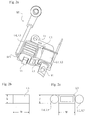
- Fig. 2a shows a preferred embodiment of the invention, where the coils L1 and L2 can be seen mounted on the same iron core T1 as the coils L4, L5 and the capacitor C1 is placed between them.
- the separate coil L3 is mounted between the other coils and is arranged to be close to the flywheel, which will be arranged in such a way that the magnet or magnets pass close to this coil L3 in order for any variations in the magnetic flux generated by the flywheel to be as accurately detected by the coil L3 as possible. It is advantageous that the separate coil L3 has a width w and a length 1 that are substantially larger than a height h (shown in Fig.
- the width w and length 1 of the coil L3 are small enough so that the magnet or magnets of the flywheel is large enough to cover a surface presented by the coil L3 as it sweeps past.
- the iron core T1 can be U-shaped with two essentially parallel extended portions so that said charge coil L1 and trig coil L2 are mounted on one of said portions and said primary and secondary coils L4, L5 are mounted on the other portion, and wherein the separate coil L3 is mounted in a space between said extended portions.
- the separate coil L3 can be placed in close vicinity to the flywheel and accurately detect any fluctuations in the magnetic flux, without depriving either of the other coils L1, L2, L4, L5 of this closeness, thereby creating optimal conditions for all coils both for the charging of the capacitor C1 and functioning of the primary and secondary coils L4, L5 for generating a spark at the spark plug SP1 and for the creations of signals at the trig coil L2 and separate coil L3 as input for the control unit M1 to control the operation of the ignition system.
- the charge capacitor C1 is charged by the charge coil L1 from which a current through the rectifier D1 is periodically generated by the rotation of the flywheel.
- the gate of the thyristor Q1 is activated by the exit OUT1 of the control unit M1 and connects the charge capacitor C1 to the ground in order for a current to flow.
- the voltage at the capacitor C1 suddenly drops, thereby creating a magnetic flux at the primary coil L4 that will be transformed into a voltage pulse in the secondary coil L5 and for a short period of time deliver the necessary voltage to the spark plug SP1 for the generation of a spark to occur.
- the timing of the signal from the control unit M1 to generate the spark is in a conventional ignition system based on the information regarding the position and rotational velocity of the flywheel that can be gathered by measuring the magnetic flux in the trig coil L2.
- This is, however, subjected to considerable disturbances by the fluctuations of the magnetic field around the iron core, especially when a spark is generated and the magnetic field suddenly changes. Therefore, the analysis of data from the trig coil L2 becomes difficult when attempting to ascertain the optimal time for spark generation, especially at times when the operation takes place at low speed (slower rotation of the flywheel) or when the engine to which the ignition system delivers sparks bounces due to high compression. At these times, there is a risk for the generation of a spark at an unsuitable time, which may considerably lower the efficiency of operation of the ignition system and the engine as a whole.
- the magnetic flux in the separate coil L3 is measured and used as input for the control unit M1 via the connection In2. Thanks to the position of the separate coil L3 at a distance from the iron core, the effect of fluctuations at spark generation will be significantly lower and a more reliable and detailed information regarding the velocity and position of the flywheel can be achieved. Based on this additional information, the timing of the spark generation can be significantly improved, and knowledge gained regarding a speed and rotational direction of the flywheel, among other things. Situations where a spark is given despite conditions being unsuitable can thus be avoided.
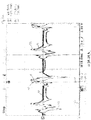
- a first signal S1 from the separate coil L3 is shown along with a second signal S2 from the trig coil L2, corresponding to the magnetic flux at these coils L2, L3 during a rotation of the flywheel of 1000 rpm in a direction suitable for spark generation at the ignition system is shown.
- a third signal S3 shows a peak 31 to indicate a passing of the flywheel with a leading north-ended magnet of a double pole bridge.
- a first peak 11 of the first signal and a first peak 21 of the second signal is created, followed after a certain amount of time by a second peak 12 of the first signal and a second peak 22 of the second signal.
- a direction of the flywheel can be determined, and by measuring the time passing between the first and second peaks 11, 12, 21, 22, the speed of the flywheel can also be measured.
- Fig. 3b the first signal S1' and second signal S2' are shown, with a third signal S3' showing a peak 31' as a flywheel with a leading south-ended magnet passes.
- a suitable direction shown by Fig. 3a
- an unsuitable direction shown by Fig. 3b
- Their placements with regard to the passing of the magnet shown by the third signal S3 are also very similar.
- the amplitude of the first peak 11 is significantly larger than that of the second peak 12 of Fig. 3a .
- the reverse is true for the first and second peaks 11', 12' of Fig. 3b , with the second peak 12' being significantly larger in amplitude than the first peak 11'. This depends on a polarization of the separate coil L3 being reversed when subjected to a leading south-ended magnet of the flywheel as compared to a north-ended.
- the first signal S1 is also more reliable than the second signal S2, since magnetic fluctuations in other parts of the ignition system will have a much smaller effect on the separate coil L3.
- the analyses according to the invention are performed using information such as amplitude and placement of the peaks of both signals S1 and S2, as described herein.
- a Hall effect sensor can be used as the separate coil (L3) and may be advantageous since the detection of magnetic flux, especially at low energies, can be very accurately detected.
- This component is, however, more expensive than conventional coils that can be very cost efficiently manufactured and used with the invention.
- the information regarding the magnetic flux that the separate coil L3 can deliver to the control unit M1 could in an alternative embodiment also be given by a sensor system comprising optical sensors for detecting the position of each magnet of the flywheel. Thereby, and by performing a series of calculations at the control unit M1, the timing of a spark can be determined with an accuracy that is close to that presented by the preferred embodiment described above.
- the trig coil L2 together with separate coil L3, is used as the timing reference.
- this has its drawback regarding noise in the signal, however this may be solved by measuring many timing pulses on the L2 at the same time, and subsequently compare those times to each other and thereby draw conclusions.
- the trig coil L2 may be used in order to further secure the function of the separate coil L3, wherein the magnetic flux detected by said trig coil L2 can provide additional information to the control unit M1. This would create a stable system where the creation of sparks in the ignition system can be controlled in an efficient way.
- flywheels with one or two magnets can be used with the invention, and the separate coil can be a choke or a hall effect sensor, for instance.
Landscapes
- Engineering & Computer Science (AREA)
- Chemical & Material Sciences (AREA)
- Combustion & Propulsion (AREA)
- Mechanical Engineering (AREA)
- General Engineering & Computer Science (AREA)
- Computer Networks & Wireless Communication (AREA)
- Signal Processing (AREA)
- Ignition Installations For Internal Combustion Engines (AREA)
Claims (9)
- Verfahren zum Überwachen einer Zündanlage, wobei die Zündanlage eine Ladespule (L1) zum Laden der Zündanlage, eine Primärspule (L4) und eine Sekundärspule (L5), wobei die Primär- und die Sekundärspule (L4, L5) dafür angeordnet sind, eine Spannung zur Funkenerzeugung zu erzeugen, ein Schwungrad, das einen oder mehrere Magneten hat, und eine Steuereinheit (M1) umfasst, gekennzeichnet durch die folgenden Schritte:a) Bereitstellen einer Auslösespule (L2),b) Bereitstellen einer gesonderten Spule (L3) mit einem Magnetkreis, der von dem Magnetkreis oder den -kreisen der Ladespule (L1), der Primärspule (L4) und der Sekundärspule (L5) gesondert ist,c) Drehen des Schwungrades, um einen Magnetfluss an der gesonderten Spule (L3) und einen Magnetfluss an der Auslösespule (L2) zu erzeugen,d) Verwenden der Steuereinheit (M1), um einen Magnetfluss an der gesonderten Spule (L3) und der Auslösespule (L2) zu überwachen, unde) Verwenden von Informationen bezüglich des Magnetflusses an der gesonderten Spule (L3) und des Magnetflusses an der Auslösespule (L2) als Eingabe zum Steuern wenigstens der Zündzeitpunktsteuerung und zum Bestimmen einer Richtung, in der sich das Schwungrad dreht.
- Verfahren nach Anspruch 1, unter Verwendung von Informationen bezüglich des Magnetflusses als Eingabe zum Bestimmen einer Geschwindigkeit des Schwungrades.
- Verfahren zum Überwachen einer Zündanlage, wobei die Zündanlage eine Ladespule (L1) zum Laden der Zündanlage, eine Primärspule (L4) und eine Sekundärspule (L5), wobei die Primär- und die Sekundärspule (L4, L5) dafür angeordnet sind, eine Spannung zur Funkenerzeugung zu erzeugen, ein Schwungrad, das einen oder mehrere Magneten, die an den Spulen entlangstreichen, hat, und eine Steuereinheit (M1) umfasst, gekennzeichnet durch die folgenden Schritte:a) Bereitstellen einer Auslösespule (L2),b) Bereitstellen eines gesonderten Sensors (L3) in Form eines Hall-Effekt-Sensors,c) Drehen des Schwungrades, um die Spannung in der Ladespule (L1) zu erzeugen und einen Magnetfluss an der Auslösespule (L2) und ein Signal von dem Hall-Effekt-Sensor (L3) zu erzeugen,d) Verwenden der Steuereinheit (M1), um ein Signal von dem Hall-Effekt-Sensor (L3) und einen Magnetfluss an der Auslösespule (L2) zu überwachen, unde) Verwenden von Informationen bezüglich des Signals von dem Hall-Effekt-Sensor (L3) und des Magnetflusses an der Auslösespule (L2) als Eingabe zum Steuern wenigstens der Zündzeitpunktsteuerung und zum Bestimmen einer Richtung, in der sich das Schwungrad dreht.
- Verfahren zum Überwachen einer Zündanlage, wobei die Zündanlage Folgendes umfasst:eine Ladespule (L1) zum Laden der Zündanlage,eine Primärspule (L4) und eine Sekundärspule (L5), wobei die Primär- und die Sekundärspule (L4, L5) dafür angeordnet sind, eine Spannung zur Funkenerzeugung zu erzeugen,ein Schwungrad, das einen oder mehrere Magneten, die an den Spulen entlangstreichen, hat,und eine Steuereinheit (M1), gekennzeichnet durch die folgenden Schritte:a) Bereitstellen einer Auslösespule (L2),b) Bereitstellen eines gesonderten Sensors (L3) in Form eines optischen Sensors,c) Drehen des Schwungrades, um die Spannung in der Ladespule (L1) zu erzeugen und einen Magnetfluss an der Auslösespule (L2) und ein Signal von dem optischen Sensor (L3) zu erzeugen,d) Verwenden der Steuereinheit (M1), um ein Signal von dem optischen Sensor (L3) und einen Magnetfluss an der Auslösespule (L2) zu überwachen, unde) Verwenden von Informationen bezüglich des Signals von dem optischen Sensor (L3) und des Magnetflusses an der Auslösespule (L2) als Eingabe zum Steuern wenigstens der Zündzeitpunktsteuerung und zum Bestimmen einer Richtung, in der sich das Schwungrad dreht.
- Steuerungssystem für eine Zündanlage, wobei die Zündanlage Folgendes umfasst:ein Schwungrad, das einen oder mehrere Magneten hat,eine Ladespule (L1) zum Laden der Zündanlage,eine Primärspule und eine Sekundärspule zum Erzeugen einer Spannung zur Funkenerzeugung,eine Auslösespule (L2), die dafür angeordnet ist, einem Magnetfeld ausgesetzt zu werden, wenn die Schwungradmagneten an der Auslösespule entlangstreichen,eine gesonderte Spule (L3), die dafür angeordnet ist, einem Magnetfeld ausgesetzt zu werden, wenn die Schwungradmagneten an der gesonderten Spule entlangstreichen und ein Magnetfluss in der gesonderten Spule erzeugt wird, wobei der Magnetkreis der gesonderten Spule von einem Magnetkreis der Ladespule, der Primärspule und der Sekundärspule gesondert ist, undeine Steuereinheit (M1), die dafür angeordnet ist, Informationen bezüglich des Magnetflusses in der gesonderten Spule und der Auslösespule zu erfassen, und wobei die Steuereinheit dafür konfiguriert ist, die Informationen als Eingabe zum Steuern wenigstens der Zündzeitpunktsteuerung der Zündanlage und zum Bestimmen einer Drehrichtung des Schwungrades zu verwenden.
- Steuerungssystem nach Anspruch 5, wobei die Ladespule (L1) und die Auslösespule (L2) auf einem Eisenkern (T1) angebracht sind und wobei die Anlage ferner eine Primärspule (L4) und eine Sekundärspule (L5) umfasst, die auf dem gleichen Eisenkern (T1) angebracht sind, und wobei die gesonderte Spule (L3) derart in einem Abstand von dem Eisenkern (T1) angebracht ist, dass die Wirkung von Schwankungen bei der Funkenerzeugung verringert werden.
- Steuerungssystem nach Anspruch 6, wobei der Eisenkern (T1) U-förmig ist, mit zwei sich im Wesentlichen parallel ausgedehnten Abschnitten, so dass die Ladespule (L1) und die Auslösespule (L2) auf einem der ausgedehnten Abschnitte angebracht sind und die Primär- und die Sekundärspule (L4, L5) auf dem anderen ausgedehnten Abschnitt angebracht sind und wobei die gesonderte Spule (L3) in einem Raum zwischen den ausgedehnten Abschnitten angebracht ist.
- Steuerungssystem für eine Zündanlage, wobei die Zündanlage Folgendes umfasst:ein Schwungrad, das einen oder mehrere Magneten hat,eine Ladespule (L1) zum Laden der Zündanlage,eine Primärspule und eine Sekundärspule zum Erzeugen einer Spannung zur Funkenerzeugung,eine Auslösespule (L2), die dafür angeordnet ist, einem Magnetfeld ausgesetzt zu werden, wenn die Schwungradmagneten an der Auslösespule entlangstreichen,einen Hall-Effekt-Sensor (L3), der dafür angeordnet ist, die Drehstellung des Schwungrades zu erfassen, wenn das Schwungrad an dem Hall-Effekt-Sensor entlangstreicht, undeine Steuereinheit (M1), die dafür angeordnet ist, Informationen bezüglich eines Signals von dem Hall-Effekt-Sensor (L3) und des Magnetflusses in der Auslösespule (L2) zu erfassen, und wobei die Steuereinheit dafür konfiguriert ist, die Informationen als Eingabe zum Steuern wenigstens der Zündzeitpunktsteuerung der Zündanlage und zum Bestimmen einer Drehrichtung des Schwungrades zu verwenden.
- Steuerungssystem für eine Zündanlage, wobei die Zündanlage Folgendes umfasst:eine Ladespule (L1) zum Laden der Zündanlage,eine Primärspule und eine Sekundärspule zum Erzeugen einer Spannung zur Funkenerzeugung,eine Spule (L2), die dafür angeordnet ist, einem Magnetfeld ausgesetzt zu werden, wenn die Schwungradmagneten an der Auslösespule entlangstreichen,einen optischen Sensor (L3), der dafür angeordnet ist, die Drehstellung des Schwungrades zu erfassen, wenn das Schwungrad an dem optischen Sensor entlangstreicht, undeine Steuereinheit (M1), die dafür angeordnet ist, Informationen bezüglich eines Signals von dem optischen Sensor (L3) und des Magnetflusses in der Auslösespule (L2) zu erfassen, und wobei die Steuereinheit dafür konfiguriert ist, die Informationen als Eingabe zum Steuern wenigstens der Zündzeitpunktsteuerung der Zündanlage und zum Bestimmen einer Drehrichtung des Schwungrades zu verwenden.
Applications Claiming Priority (2)
| Application Number | Priority Date | Filing Date | Title |
|---|---|---|---|
| SE0950836 | 2009-11-06 | ||
| PCT/SE2010/051216 WO2011056141A1 (en) | 2009-11-06 | 2010-11-08 | Ignition system control method and system |
Publications (3)
| Publication Number | Publication Date |
|---|---|
| EP2496826A1 EP2496826A1 (de) | 2012-09-12 |
| EP2496826A4 EP2496826A4 (de) | 2017-01-25 |
| EP2496826B1 true EP2496826B1 (de) | 2018-07-04 |
Family
ID=43970174
Family Applications (1)
| Application Number | Title | Priority Date | Filing Date |
|---|---|---|---|
| EP10828628.7A Active EP2496826B1 (de) | 2009-11-06 | 2010-11-08 | Verfahren und system zur steuerung eines zündsystems |
Country Status (8)
| Country | Link |
|---|---|
| US (1) | US9243602B2 (de) |
| EP (1) | EP2496826B1 (de) |
| JP (1) | JP5817732B2 (de) |
| CN (1) | CN102782308B (de) |
| BR (1) | BR112012010611A2 (de) |
| CA (1) | CA2779175C (de) |
| RU (1) | RU2556870C2 (de) |
| WO (1) | WO2011056141A1 (de) |
Families Citing this family (2)
| Publication number | Priority date | Publication date | Assignee | Title |
|---|---|---|---|---|
| JP5908164B2 (ja) * | 2013-03-25 | 2016-04-26 | 新電元工業株式会社 | 点火制御装置および点火制御方法 |
| JP6791786B2 (ja) * | 2017-02-22 | 2020-11-25 | 株式会社やまびこ | エンジンのノッキング検出装置 |
Family Cites Families (18)
| Publication number | Priority date | Publication date | Assignee | Title |
|---|---|---|---|---|
| US3955549A (en) * | 1974-10-29 | 1976-05-11 | R. E. Phelon Company, Inc. | CD ignition system with anti-reverse feature |
| US4155341A (en) * | 1977-03-28 | 1979-05-22 | Gulf & Western Manufacturing Company | Ignition system |
| US4852540A (en) * | 1988-05-09 | 1989-08-01 | F & B Mfg Co. | High-efficiency charging and regulating system |
| US4901704A (en) * | 1988-05-09 | 1990-02-20 | F & B Mfg. Co. | Hall effect device ignition and charging system |
| DE3914026C1 (de) * | 1989-04-28 | 1990-09-06 | Pruefrex-Elektro-Apparatebau Inh. Helga Mueller, Geb. Dutschke, 8501 Cadolzburg, De | |
| US5070727A (en) | 1990-11-16 | 1991-12-10 | General Motors Corporation | Crankshaft angular position detecting apparatus |
| US5551397A (en) * | 1995-03-13 | 1996-09-03 | Early; Derrick A. | Digitally controlled magneto ignition system with alternate timing |
| US6009865A (en) * | 1998-09-23 | 2000-01-04 | Walbro Corporation | Low speed ignition system |
| DE10107070A1 (de) * | 2000-10-13 | 2002-04-25 | Pruefrex Elektro Appbau Inh He | Drehrichtungserkennung in einer Zündanlage einer Brennkraftmaschine |
| US6691689B2 (en) | 2000-10-13 | 2004-02-17 | Prüfrex-Elektro-Apparatebau, Inh. Helga Müller. Geb Dutschke | Rotation direction detector in ignition equipment of an internal combustion engine |
| US6805109B2 (en) * | 2002-09-18 | 2004-10-19 | Thomas L. Cowan | Igniter circuit with an air gap |
| US7111618B1 (en) * | 2002-10-29 | 2006-09-26 | R.E. Phelon Company, Inc. | Radial stator and flywheel assembly |
| US7069140B2 (en) * | 2004-06-30 | 2006-06-27 | General Electric Company | Engine operation without cam sensor |
| US7121270B1 (en) | 2005-08-29 | 2006-10-17 | Vimx Technologies Inc. | Spark generation method and ignition system using same |
| US7404396B2 (en) * | 2006-02-08 | 2008-07-29 | Denso Corporation | Multiple discharge ignition control apparatus and method for internal combustion engines |
| SE529860C2 (sv) * | 2006-04-03 | 2007-12-11 | Sem Ab | Metod och anordning för att höja gnistenergin i kapacitiva tändsystem |
| US7546836B2 (en) | 2007-01-26 | 2009-06-16 | Walbro Engine Management, L.L.C. | Ignition module for use with a light-duty internal combustion engine |
| US8490609B2 (en) | 2008-02-07 | 2013-07-23 | Sem Aktiebolag | System for energy support in a CDI system |
-
2010
- 2010-11-08 WO PCT/SE2010/051216 patent/WO2011056141A1/en not_active Ceased
- 2010-11-08 RU RU2012117959/07A patent/RU2556870C2/ru active
- 2010-11-08 CA CA2779175A patent/CA2779175C/en not_active Expired - Fee Related
- 2010-11-08 EP EP10828628.7A patent/EP2496826B1/de active Active
- 2010-11-08 JP JP2012536759A patent/JP5817732B2/ja not_active Expired - Fee Related
- 2010-11-08 CN CN201080060699.0A patent/CN102782308B/zh active Active
- 2010-11-08 US US13/503,731 patent/US9243602B2/en not_active Expired - Fee Related
- 2010-11-08 BR BR112012010611A patent/BR112012010611A2/pt not_active IP Right Cessation
Non-Patent Citations (1)
| Title |
|---|
| None * |
Also Published As
| Publication number | Publication date |
|---|---|
| EP2496826A1 (de) | 2012-09-12 |
| CN102782308A (zh) | 2012-11-14 |
| WO2011056141A1 (en) | 2011-05-12 |
| CA2779175C (en) | 2017-03-07 |
| RU2556870C2 (ru) | 2015-07-20 |
| BR112012010611A2 (pt) | 2016-03-22 |
| JP2013510253A (ja) | 2013-03-21 |
| RU2012117959A (ru) | 2013-12-20 |
| CA2779175A1 (en) | 2011-05-12 |
| US9243602B2 (en) | 2016-01-26 |
| JP5817732B2 (ja) | 2015-11-18 |
| EP2496826A4 (de) | 2017-01-25 |
| CN102782308B (zh) | 2015-07-08 |
| US20120255530A1 (en) | 2012-10-11 |
Similar Documents
| Publication | Publication Date | Title |
|---|---|---|
| US4934192A (en) | Turbine blade vibration detection system | |
| EP0188180B1 (de) | Methode und Einrichtung zum Nachweis des Ionisierungsstroms bei einem Verbrennungskraftmaschinenzündsystem | |
| SE440535B (sv) | Elektronisk motorknackningsdetekterande anordning | |
| JPH05133312A (ja) | 内燃機関用イグニツシヨン装置 | |
| US6034525A (en) | Method and apparatus for detecting rotational direction of a two cycle engine | |
| JP2004304999A (ja) | 発電機界磁巻線における短絡巻きのオンライン検出 | |
| US4503391A (en) | Rotary angular position sensor with magnet and pole disk assembly mounted on rotatable shaft | |
| CA2779175C (en) | Ignition system control method and system | |
| US4164706A (en) | Rotational position detector utilizing an FET blocking oscillator | |
| US7047956B2 (en) | Kickback preventing device for engine | |
| US20050139194A1 (en) | Ignition control apparatus for internal combustion engine | |
| US6885186B2 (en) | Resonant circuit for increasing variable reluctance sensor output | |
| US4491121A (en) | Ignition system for two-cycle engine | |
| JP3421211B2 (ja) | 内燃機関の点火制御装置 | |
| JP4394015B2 (ja) | コイル耐圧試験器 | |
| US20080011272A1 (en) | Apparatus and method for ignition timing for small gasoline engine | |
| US20140260507A1 (en) | Pulse duration extender | |
| JP2009281161A (ja) | 内燃機関のダイアグ装置 | |
| US20050231191A1 (en) | Tachometer pulse detection method and circuit | |
| US9417096B2 (en) | Rotation direction detection of an ignition device | |
| JP5142087B2 (ja) | 内燃機関のイオン電流検出装置 | |
| JPWO2020121515A1 (ja) | 点火装置 | |
| JP3710064B2 (ja) | 内燃機関のイオン電流検出装置 | |
| CN106093457A (zh) | 转速传感器 | |
| KR100751037B1 (ko) | 전기 모터를 제어 및 보호하기 위한 방법과, 전기 모터를제어하기 위한 시스템 및 전기 모터 시스템 |
Legal Events
| Date | Code | Title | Description |
|---|---|---|---|
| PUAI | Public reference made under article 153(3) epc to a published international application that has entered the european phase |
Free format text: ORIGINAL CODE: 0009012 |
|
| 17P | Request for examination filed |
Effective date: 20120423 |
|
| AK | Designated contracting states |
Kind code of ref document: A1 Designated state(s): AL AT BE BG CH CY CZ DE DK EE ES FI FR GB GR HR HU IE IS IT LI LT LU LV MC MK MT NL NO PL PT RO RS SE SI SK SM TR |
|
| DAX | Request for extension of the european patent (deleted) | ||
| RA4 | Supplementary search report drawn up and despatched (corrected) |
Effective date: 20170102 |
|
| RIC1 | Information provided on ipc code assigned before grant |
Ipc: F02P 1/00 20060101ALI20161221BHEP Ipc: F02P 7/067 20060101AFI20161221BHEP Ipc: F02P 7/07 20060101ALI20161221BHEP Ipc: F02P 5/04 20060101ALI20161221BHEP |
|
| GRAP | Despatch of communication of intention to grant a patent |
Free format text: ORIGINAL CODE: EPIDOSNIGR1 |
|
| INTG | Intention to grant announced |
Effective date: 20180404 |
|
| GRAS | Grant fee paid |
Free format text: ORIGINAL CODE: EPIDOSNIGR3 |
|
| GRAA | (expected) grant |
Free format text: ORIGINAL CODE: 0009210 |
|
| AK | Designated contracting states |
Kind code of ref document: B1 Designated state(s): AL AT BE BG CH CY CZ DE DK EE ES FI FR GB GR HR HU IE IS IT LI LT LU LV MC MK MT NL NO PL PT RO RS SE SI SK SM TR |
|
| REG | Reference to a national code |
Ref country code: GB Ref legal event code: FG4D |
|
| REG | Reference to a national code |
Ref country code: CH Ref legal event code: EP |
|
| REG | Reference to a national code |
Ref country code: AT Ref legal event code: REF Ref document number: 1014783 Country of ref document: AT Kind code of ref document: T Effective date: 20180715 |
|
| REG | Reference to a national code |
Ref country code: IE Ref legal event code: FG4D |
|
| REG | Reference to a national code |
Ref country code: DE Ref legal event code: R096 Ref document number: 602010051717 Country of ref document: DE |
|
| REG | Reference to a national code |
Ref country code: SE Ref legal event code: TRGR |
|
| REG | Reference to a national code |
Ref country code: NL Ref legal event code: MP Effective date: 20180704 |
|
| REG | Reference to a national code |
Ref country code: LT Ref legal event code: MG4D |
|
| REG | Reference to a national code |
Ref country code: AT Ref legal event code: MK05 Ref document number: 1014783 Country of ref document: AT Kind code of ref document: T Effective date: 20180704 |
|
| PG25 | Lapsed in a contracting state [announced via postgrant information from national office to epo] |
Ref country code: NL Free format text: LAPSE BECAUSE OF FAILURE TO SUBMIT A TRANSLATION OF THE DESCRIPTION OR TO PAY THE FEE WITHIN THE PRESCRIBED TIME-LIMIT Effective date: 20180704 |
|
| PG25 | Lapsed in a contracting state [announced via postgrant information from national office to epo] |
Ref country code: AT Free format text: LAPSE BECAUSE OF FAILURE TO SUBMIT A TRANSLATION OF THE DESCRIPTION OR TO PAY THE FEE WITHIN THE PRESCRIBED TIME-LIMIT Effective date: 20180704 Ref country code: IS Free format text: LAPSE BECAUSE OF FAILURE TO SUBMIT A TRANSLATION OF THE DESCRIPTION OR TO PAY THE FEE WITHIN THE PRESCRIBED TIME-LIMIT Effective date: 20181104 Ref country code: FI Free format text: LAPSE BECAUSE OF FAILURE TO SUBMIT A TRANSLATION OF THE DESCRIPTION OR TO PAY THE FEE WITHIN THE PRESCRIBED TIME-LIMIT Effective date: 20180704 Ref country code: NO Free format text: LAPSE BECAUSE OF FAILURE TO SUBMIT A TRANSLATION OF THE DESCRIPTION OR TO PAY THE FEE WITHIN THE PRESCRIBED TIME-LIMIT Effective date: 20181004 Ref country code: RS Free format text: LAPSE BECAUSE OF FAILURE TO SUBMIT A TRANSLATION OF THE DESCRIPTION OR TO PAY THE FEE WITHIN THE PRESCRIBED TIME-LIMIT Effective date: 20180704 Ref country code: GR Free format text: LAPSE BECAUSE OF FAILURE TO SUBMIT A TRANSLATION OF THE DESCRIPTION OR TO PAY THE FEE WITHIN THE PRESCRIBED TIME-LIMIT Effective date: 20181005 Ref country code: BG Free format text: LAPSE BECAUSE OF FAILURE TO SUBMIT A TRANSLATION OF THE DESCRIPTION OR TO PAY THE FEE WITHIN THE PRESCRIBED TIME-LIMIT Effective date: 20181004 Ref country code: CZ Free format text: LAPSE BECAUSE OF FAILURE TO SUBMIT A TRANSLATION OF THE DESCRIPTION OR TO PAY THE FEE WITHIN THE PRESCRIBED TIME-LIMIT Effective date: 20180704 Ref country code: PL Free format text: LAPSE BECAUSE OF FAILURE TO SUBMIT A TRANSLATION OF THE DESCRIPTION OR TO PAY THE FEE WITHIN THE PRESCRIBED TIME-LIMIT Effective date: 20180704 Ref country code: LT Free format text: LAPSE BECAUSE OF FAILURE TO SUBMIT A TRANSLATION OF THE DESCRIPTION OR TO PAY THE FEE WITHIN THE PRESCRIBED TIME-LIMIT Effective date: 20180704 |
|
| PG25 | Lapsed in a contracting state [announced via postgrant information from national office to epo] |
Ref country code: HR Free format text: LAPSE BECAUSE OF FAILURE TO SUBMIT A TRANSLATION OF THE DESCRIPTION OR TO PAY THE FEE WITHIN THE PRESCRIBED TIME-LIMIT Effective date: 20180704 Ref country code: LV Free format text: LAPSE BECAUSE OF FAILURE TO SUBMIT A TRANSLATION OF THE DESCRIPTION OR TO PAY THE FEE WITHIN THE PRESCRIBED TIME-LIMIT Effective date: 20180704 Ref country code: AL Free format text: LAPSE BECAUSE OF FAILURE TO SUBMIT A TRANSLATION OF THE DESCRIPTION OR TO PAY THE FEE WITHIN THE PRESCRIBED TIME-LIMIT Effective date: 20180704 Ref country code: ES Free format text: LAPSE BECAUSE OF FAILURE TO SUBMIT A TRANSLATION OF THE DESCRIPTION OR TO PAY THE FEE WITHIN THE PRESCRIBED TIME-LIMIT Effective date: 20180704 |
|
| REG | Reference to a national code |
Ref country code: DE Ref legal event code: R097 Ref document number: 602010051717 Country of ref document: DE |
|
| PG25 | Lapsed in a contracting state [announced via postgrant information from national office to epo] |
Ref country code: RO Free format text: LAPSE BECAUSE OF FAILURE TO SUBMIT A TRANSLATION OF THE DESCRIPTION OR TO PAY THE FEE WITHIN THE PRESCRIBED TIME-LIMIT Effective date: 20180704 Ref country code: EE Free format text: LAPSE BECAUSE OF FAILURE TO SUBMIT A TRANSLATION OF THE DESCRIPTION OR TO PAY THE FEE WITHIN THE PRESCRIBED TIME-LIMIT Effective date: 20180704 |
|
| PLBE | No opposition filed within time limit |
Free format text: ORIGINAL CODE: 0009261 |
|
| STAA | Information on the status of an ep patent application or granted ep patent |
Free format text: STATUS: NO OPPOSITION FILED WITHIN TIME LIMIT |
|
| PG25 | Lapsed in a contracting state [announced via postgrant information from national office to epo] |
Ref country code: SM Free format text: LAPSE BECAUSE OF FAILURE TO SUBMIT A TRANSLATION OF THE DESCRIPTION OR TO PAY THE FEE WITHIN THE PRESCRIBED TIME-LIMIT Effective date: 20180704 Ref country code: DK Free format text: LAPSE BECAUSE OF FAILURE TO SUBMIT A TRANSLATION OF THE DESCRIPTION OR TO PAY THE FEE WITHIN THE PRESCRIBED TIME-LIMIT Effective date: 20180704 Ref country code: SK Free format text: LAPSE BECAUSE OF FAILURE TO SUBMIT A TRANSLATION OF THE DESCRIPTION OR TO PAY THE FEE WITHIN THE PRESCRIBED TIME-LIMIT Effective date: 20180704 |
|
| 26N | No opposition filed |
Effective date: 20190405 |
|
| REG | Reference to a national code |
Ref country code: CH Ref legal event code: PL |
|
| GBPC | Gb: european patent ceased through non-payment of renewal fee |
Effective date: 20181108 |
|
| PG25 | Lapsed in a contracting state [announced via postgrant information from national office to epo] |
Ref country code: MC Free format text: LAPSE BECAUSE OF FAILURE TO SUBMIT A TRANSLATION OF THE DESCRIPTION OR TO PAY THE FEE WITHIN THE PRESCRIBED TIME-LIMIT Effective date: 20180704 Ref country code: LU Free format text: LAPSE BECAUSE OF NON-PAYMENT OF DUE FEES Effective date: 20181108 |
|
| REG | Reference to a national code |
Ref country code: BE Ref legal event code: MM Effective date: 20181130 |
|
| REG | Reference to a national code |
Ref country code: IE Ref legal event code: MM4A |
|
| PG25 | Lapsed in a contracting state [announced via postgrant information from national office to epo] |
Ref country code: CH Free format text: LAPSE BECAUSE OF NON-PAYMENT OF DUE FEES Effective date: 20181130 Ref country code: SI Free format text: LAPSE BECAUSE OF FAILURE TO SUBMIT A TRANSLATION OF THE DESCRIPTION OR TO PAY THE FEE WITHIN THE PRESCRIBED TIME-LIMIT Effective date: 20180704 Ref country code: LI Free format text: LAPSE BECAUSE OF NON-PAYMENT OF DUE FEES Effective date: 20181130 |
|
| PG25 | Lapsed in a contracting state [announced via postgrant information from national office to epo] |
Ref country code: IE Free format text: LAPSE BECAUSE OF NON-PAYMENT OF DUE FEES Effective date: 20181108 |
|
| PG25 | Lapsed in a contracting state [announced via postgrant information from national office to epo] |
Ref country code: BE Free format text: LAPSE BECAUSE OF NON-PAYMENT OF DUE FEES Effective date: 20181130 |
|
| PG25 | Lapsed in a contracting state [announced via postgrant information from national office to epo] |
Ref country code: GB Free format text: LAPSE BECAUSE OF NON-PAYMENT OF DUE FEES Effective date: 20181108 |
|
| PG25 | Lapsed in a contracting state [announced via postgrant information from national office to epo] |
Ref country code: MT Free format text: LAPSE BECAUSE OF NON-PAYMENT OF DUE FEES Effective date: 20181108 |
|
| PG25 | Lapsed in a contracting state [announced via postgrant information from national office to epo] |
Ref country code: TR Free format text: LAPSE BECAUSE OF FAILURE TO SUBMIT A TRANSLATION OF THE DESCRIPTION OR TO PAY THE FEE WITHIN THE PRESCRIBED TIME-LIMIT Effective date: 20180704 |
|
| PG25 | Lapsed in a contracting state [announced via postgrant information from national office to epo] |
Ref country code: PT Free format text: LAPSE BECAUSE OF FAILURE TO SUBMIT A TRANSLATION OF THE DESCRIPTION OR TO PAY THE FEE WITHIN THE PRESCRIBED TIME-LIMIT Effective date: 20180704 |
|
| PG25 | Lapsed in a contracting state [announced via postgrant information from national office to epo] |
Ref country code: MK Free format text: LAPSE BECAUSE OF NON-PAYMENT OF DUE FEES Effective date: 20180704 Ref country code: CY Free format text: LAPSE BECAUSE OF FAILURE TO SUBMIT A TRANSLATION OF THE DESCRIPTION OR TO PAY THE FEE WITHIN THE PRESCRIBED TIME-LIMIT Effective date: 20180704 Ref country code: HU Free format text: LAPSE BECAUSE OF FAILURE TO SUBMIT A TRANSLATION OF THE DESCRIPTION OR TO PAY THE FEE WITHIN THE PRESCRIBED TIME-LIMIT; INVALID AB INITIO Effective date: 20101108 |
|
| PGFP | Annual fee paid to national office [announced via postgrant information from national office to epo] |
Ref country code: FR Payment date: 20211115 Year of fee payment: 12 |
|
| PGFP | Annual fee paid to national office [announced via postgrant information from national office to epo] |
Ref country code: IT Payment date: 20211118 Year of fee payment: 12 |
|
| PG25 | Lapsed in a contracting state [announced via postgrant information from national office to epo] |
Ref country code: IT Free format text: LAPSE BECAUSE OF NON-PAYMENT OF DUE FEES Effective date: 20221108 |
|
| PG25 | Lapsed in a contracting state [announced via postgrant information from national office to epo] |
Ref country code: FR Free format text: LAPSE BECAUSE OF NON-PAYMENT OF DUE FEES Effective date: 20221130 |
|
| PGFP | Annual fee paid to national office [announced via postgrant information from national office to epo] |
Ref country code: DE Payment date: 20251022 Year of fee payment: 16 |
|
| PGFP | Annual fee paid to national office [announced via postgrant information from national office to epo] |
Ref country code: SE Payment date: 20251022 Year of fee payment: 16 |