EP2496795B1 - Turbomachine a double flux pour aeronef, comprenant des moyens structuraux de rigidification du carter central - Google Patents
Turbomachine a double flux pour aeronef, comprenant des moyens structuraux de rigidification du carter central Download PDFInfo
- Publication number
- EP2496795B1 EP2496795B1 EP10771484.2A EP10771484A EP2496795B1 EP 2496795 B1 EP2496795 B1 EP 2496795B1 EP 10771484 A EP10771484 A EP 10771484A EP 2496795 B1 EP2496795 B1 EP 2496795B1
- Authority
- EP
- European Patent Office
- Prior art keywords
- casing
- central casing
- structural
- turbomachine
- ferrule
- Prior art date
- Legal status (The legal status is an assumption and is not a legal conclusion. Google has not performed a legal analysis and makes no representation as to the accuracy of the status listed.)
- Active
Links
Images

Classifications
-
- F—MECHANICAL ENGINEERING; LIGHTING; HEATING; WEAPONS; BLASTING
- F01—MACHINES OR ENGINES IN GENERAL; ENGINE PLANTS IN GENERAL; STEAM ENGINES
- F01D—NON-POSITIVE DISPLACEMENT MACHINES OR ENGINES, e.g. STEAM TURBINES
- F01D25/00—Component parts, details, or accessories, not provided for in, or of interest apart from, other groups
- F01D25/24—Casings; Casing parts, e.g. diaphragms, casing fastenings
-
- F—MECHANICAL ENGINEERING; LIGHTING; HEATING; WEAPONS; BLASTING
- F01—MACHINES OR ENGINES IN GENERAL; ENGINE PLANTS IN GENERAL; STEAM ENGINES
- F01D—NON-POSITIVE DISPLACEMENT MACHINES OR ENGINES, e.g. STEAM TURBINES
- F01D25/00—Component parts, details, or accessories, not provided for in, or of interest apart from, other groups
- F01D25/28—Supporting or mounting arrangements, e.g. for turbine casing
-
- F—MECHANICAL ENGINEERING; LIGHTING; HEATING; WEAPONS; BLASTING
- F02—COMBUSTION ENGINES; HOT-GAS OR COMBUSTION-PRODUCT ENGINE PLANTS
- F02C—GAS-TURBINE PLANTS; AIR INTAKES FOR JET-PROPULSION PLANTS; CONTROLLING FUEL SUPPLY IN AIR-BREATHING JET-PROPULSION PLANTS
- F02C7/00—Features, components parts, details or accessories, not provided for in, or of interest apart form groups F02C1/00 - F02C6/00; Air intakes for jet-propulsion plants
-
- F—MECHANICAL ENGINEERING; LIGHTING; HEATING; WEAPONS; BLASTING
- F02—COMBUSTION ENGINES; HOT-GAS OR COMBUSTION-PRODUCT ENGINE PLANTS
- F02K—JET-PROPULSION PLANTS
- F02K3/00—Plants including a gas turbine driving a compressor or a ducted fan
- F02K3/02—Plants including a gas turbine driving a compressor or a ducted fan in which part of the working fluid by-passes the turbine and combustion chamber
- F02K3/04—Plants including a gas turbine driving a compressor or a ducted fan in which part of the working fluid by-passes the turbine and combustion chamber the plant including ducted fans, i.e. fans with high volume, low pressure outputs, for augmenting the jet thrust, e.g. of double-flow type
- F02K3/06—Plants including a gas turbine driving a compressor or a ducted fan in which part of the working fluid by-passes the turbine and combustion chamber the plant including ducted fans, i.e. fans with high volume, low pressure outputs, for augmenting the jet thrust, e.g. of double-flow type with front fan
-
- F—MECHANICAL ENGINEERING; LIGHTING; HEATING; WEAPONS; BLASTING
- F04—POSITIVE - DISPLACEMENT MACHINES FOR LIQUIDS; PUMPS FOR LIQUIDS OR ELASTIC FLUIDS
- F04D—NON-POSITIVE-DISPLACEMENT PUMPS
- F04D29/00—Details, component parts, or accessories
- F04D29/40—Casings; Connections of working fluid
- F04D29/403—Casings; Connections of working fluid especially adapted for elastic fluid pumps
-
- F—MECHANICAL ENGINEERING; LIGHTING; HEATING; WEAPONS; BLASTING
- F05—INDEXING SCHEMES RELATING TO ENGINES OR PUMPS IN VARIOUS SUBCLASSES OF CLASSES F01-F04
- F05D—INDEXING SCHEME FOR ASPECTS RELATING TO NON-POSITIVE-DISPLACEMENT MACHINES OR ENGINES, GAS-TURBINES OR JET-PROPULSION PLANTS
- F05D2240/00—Components
- F05D2240/10—Stators
- F05D2240/14—Casings or housings protecting or supporting assemblies within
-
- F—MECHANICAL ENGINEERING; LIGHTING; HEATING; WEAPONS; BLASTING
- F05—INDEXING SCHEMES RELATING TO ENGINES OR PUMPS IN VARIOUS SUBCLASSES OF CLASSES F01-F04
- F05D—INDEXING SCHEME FOR ASPECTS RELATING TO NON-POSITIVE-DISPLACEMENT MACHINES OR ENGINES, GAS-TURBINES OR JET-PROPULSION PLANTS
- F05D2250/00—Geometry
- F05D2250/30—Arrangement of components
Definitions
- the present invention relates generally to a turbofan engine for aircraft, preferably of the turbojet type.
- said envelope means comprise on the one hand a structural upstream shell mounted on the inner ferrule of the intermediate casing and defining the front part of the second internal delimiting surface, and on the other hand a main casing extending towards the inside. rear said upstream ferrule.
- said turbomachine comprises structural means for stiffening the central housing, surrounded by said main envelope, and extending rearwardly between the upstream shell and the central casing on which these means are mounted.
- the invention proposes a simple, clever and space-saving solution for limiting the bending of the central casing during the operation of the turbomachine, thus implying an increase in the overall performance of the latter.
- said structural means for stiffening the central casing take the form of a perforated annular structure.
- said structural means for stiffening the central casing take the form of a plurality of rods spaced circumferentially from each other.
- said structural means for stiffening the central casing extend substantially parallel to the longitudinal axis of the turbomachine.
- said main envelope comprises a plurality of aerodynamic panels mounted on support rails reported at their front end to the structural inner shroud, and at their rear end on a support ring located near a junction between said crankcase. central and an exhaust casing extending it to the rear.
- said structural means for stiffening the central casing are mounted on a portion thereof located in line with a junction zone between a compressor and a combustion chamber of the turbomachine.
- the turbomachine comprises a centrifugal high pressure compressor, allowing, at the right of a downstream end thereof, to move as far as possible the central casing of the longitudinal axis of the engine.
- This part of the central casing can then, as mentioned above, be used for the connection of the structural stiffening means.
- an aircraft turbojet engine 1 can be seen according to a first preferred embodiment.
- front and rear are to be considered in relation to a direction of advancement of the aircraft caused by the thrust of the turbojet engine, this direction being represented schematically by the arrow 2.
- upstream and downstream are to be considered with respect to a main flow direction of the gases within the turbojet, contrary to the direction of advance 2 of the aircraft.
- the turbojet engine 1 of longitudinal axis 4, comprises from upstream to downstream a fan 6, a low pressure compressor 8, a high pressure compressor 10, an annular combustion chamber 12, a high pressure turbine 14 and a low pressure turbine 16
- the compressors, the turbines and the combustion chamber constitute the gas generator, which is partly closed by a central casing 18 centered on the axis 4, and which is crossed by a primary flow Fp of the turbojet engine.
- the high-pressure compressor 10 is here centrifugal, and therefore comprises a centrifugal wheel that allows, at the right of a downstream end of the wheel, to radially distance at the maximum the central casing 18 of the axis 4. It follows the presence of a portion 18a of the central casing, located in line with a junction zone 11 between the centrifugal wheel and the combustion chamber 12, which is thus radially distant from the axis 4, protruding outwardly relative to to its adjacent upstream and downstream parts.
- This central casing 18 extends rearwardly an intermediate casing 20 equipped with an inner ferrule 22 and a concentric outer shell 24, between which are arranged structural arms 26 which connect them.
- the outer shell 24 is located in the rear aerodynamic extension of the fan casing 28, while the inner shell 22 is radially outward relative to the front end of the central casing 18, fixed on a hub 30 of the intermediate casing .
- All of the aforementioned housings are fixed to each other, in order to jointly form a structure through which transit static and dynamic forces.
- First casing means 36 are arranged in the rear aerodynamic extension of the inner shell 22, being arranged around the central casing 18. These means, called “Inner Fan Duct", externally have an annular surface 37 of internal delimitation. an annular secondary vein 38, through which the secondary flow Fs of the turbojet engine passes.
- the surface 37 is in the rear aerodynamic extension of another surface 39 also serving for the internal delimitation of the annular secondary vein 38, this surface 39 being defined by the inner ferrule 22.
- a mixer 48 downstream of the surface 37 is found a mixer 48 whose known function lies in the mixture of primary flow Fp and secondary Fs.
- the annular space 46 left free between the central casing 18 and the first envelope means performs the compartment function, called "Core compartment", in which are arranged equipment.
- Second means 41 forming an envelope are arranged concentrically and externally to the first means 36 above, in the rear aerodynamic extension of the outer shell 24.
- These means called in English "Outer Fan Duct", internally have an annular surface 42 of external delimitation of the vein 38.
- the surface 42 is in the rear aerodynamic extension of another 43 surface also serving for the external delimitation of the annular secondary vein 38, this surface 43 being defined by the outer shell 24.
- These second envelope means are preferably attached to the nacelle 50.
- they are connected to the exhaust casing 32 by a plurality of rods 52 connected to the latter, arranged in a transverse plane of the turbojet engine and passing through said first means 36 forming an envelope, the connection of which with the mixer 48 is located downstream of these rods 52.
- first means 36 forming envelope they are decomposed into three axially adjacent parts, the first being a structural upstream shell 54, the second a main envelope 56 preferably non-structural, and the third a ring 58 aerodynamic junction between the main envelope 56 and the mixer 48.
- the upstream structural shell 54 preferably metal, extends substantially parallel to the axis 4 on which it is centered. Its front end is flanged on the rear end of the inner ferrule 22 of the intermediate casing, so that the aerodynamic surface 39 is in the forward continuity of the front portion 37a of the inner boundary surface 37 of the secondary annular vein 38.
- the aerodynamic junction ring 58 between the main envelope 56 and the mixer 48 has a front end fixed to the rear end of the main envelope 56, so that the aerodynamic surface 37b is in front continuity of the rear portion 37c of the internal boundary surface 37, defined by this ring 58.
- the ring 58 has notches 59 for the passage of connecting rods 52 which pass through it, in order to connect the exhaust casing 32 to the second means 41 forming an outer envelope.
- the aerodynamic surfaces 39, 37a, 37b, 37c together form a continuous surface of internal delimitation of the secondary flow Fs.
- the main envelope 56 comprises a plurality of aerodynamic panels 60 as well as supporting spars 62 carrying the panels 60.
- the spars 62 are for example four in number, distributed at 90 °, and each extending between a front end fixedly mounted on the rear end of the upstream structural shell 54, and a rear end mounted on a support ring 66 centered on the axis 4.
- This support is around and near a junction between the central casing 18 and the exhaust casing 32, by being connected by conventional means, for example of the type pins, shown schematically and referenced 68 on the figure 1 .
- Each panel 60 is then supported and fixed by two directly consecutive longitudinal members 62, respectively at its two circumferential ends. Its upstream and downstream ends are in turn in the aerodynamic continuity of the upstream structural shell 54 and the ring 58, respectively.
- these panels 60 which form the aerodynamic surface 37b together with the non-covered parts of the longitudinal members 62, are preferably acoustically treated, and have manholes 70 for access to the equipment of the compartment 46. In this respect, it is stated that manholes may also be provided on the longitudinal members 62.
- the turbojet engine also comprises structural means for stiffening the central casing, these means taking here the form of a perforated annular structure 72.
- This structure 72 in the form of a ferrule, which extends substantially parallel to the axis 4, is arranged in the rear extension of the structural upstream shell 54.
- its front end is indeed fixedly mounted by bolted flanges on the rear end of the upstream structural shell 54, as well as the main envelope 56 surrounding it. So, the design proposed is such that the structural upstream ferrule 54, performing aerodynamic and mechanical functions, splits backwards into a main envelope 56 ensuring the continuity of the aerodynamic function, and an annular structure 72 ensuring the continuity of the mechanical function.
- the structure 72 extends rearwardly in a substantially constant diameter and identical to that of the structural upstream shell 54, to its rear end fixedly mounted by bolts on the annular portion 18a of the central casing, situated in line with the junction zone 11 between the centrifugal impeller of the high pressure compressor 10 and the combustion chamber 12.
- This annular stiffening structure 72 is therefore at a significant radial distance from the axis 4, allowing it to be only weakly thermally stressed .
- Holes 74 in the form of manholes may be made on this structure, always in such a way as to facilitate access to the equipment of compartment 46.
- the only change made from the first mode described above lies in the design of the structural means of rigidification, which here take the form of a plurality of rods 172 spaced circumferentially from each other, and each substantially parallel to the axis 4.
Landscapes
- Engineering & Computer Science (AREA)
- Mechanical Engineering (AREA)
- General Engineering & Computer Science (AREA)
- Chemical & Material Sciences (AREA)
- Combustion & Propulsion (AREA)
- Structures Of Non-Positive Displacement Pumps (AREA)
- Turbine Rotor Nozzle Sealing (AREA)
Description
- La présente invention se rapporte de façon générale à une turbomachine à double flux pour aéronef, de préférence du type turboréacteur.
- Sur ces turbomachines, une problématique connue réside dans la flexion du carter central renfermant le générateur des gaz, cette flexion selon l'axe transversal ayant pour conséquence d'accélérer l'usure des aubes tournantes de compresseur, et donc d'augmenter les jeux en bout d'aubes. Cet effet a pour conséquence une baisse importante du rendement global de la turbomachine.
-
- Pour faire face à ce problème de flexion du carter central, l'invention propose conformément à la revendication 1 une turbomachine à double flux pour aéronef comprenant :
- un carter intermédiaire comportant une virole intérieure et une virole extérieure entre lesquelles sont agencés des bras structuraux, la virole intérieure présentant une première surface de délimitation interne d'une veine secondaire annulaire ;
- un carter central prolongeant ledit carter intermédiaire vers l'arrière ; et
- des moyens formant enveloppe agencés dans le prolongement arrière de ladite virole intérieure du carter intermédiaire et disposés autour dudit carter central, ces moyens présentant une seconde surface de délimitation interne de la veine secondaire annulaire se situant dans le prolongement arrière de ladite première surface de délimitation interne.
- Selon l'invention, lesdits moyens formant enveloppe comportent d'une part une virole amont structurale montée sur la virole intérieure du carter intermédiaire et définissant la partie avant de la seconde surface de délimitation interne, et d'autre part une enveloppe principale prolongeant vers l'arrière ladite virole amont. De plus, ladite turbomachine comporte des moyens structuraux de rigidification du carter central, entourés par ladite enveloppe principale, et s'étendant vers l'arrière entre la virole amont et le carter central sur lesquels ces moyens sont montés.
- Par conséquent, l'invention propose une solution simple, astucieuse et peu encombrante permettant de limiter la flexion du carter central durant le fonctionnement de la turbomachine, impliquant donc une augmentation des performances globales de celle-ci.
- Selon un premier mode de réalisation préféré de la présente invention, lesdits moyens structuraux de rigidification du carter central prennent la forme d'une structure annulaire ajourée.
- Selon un second mode de réalisation préféré de la présente invention, lesdits moyens structuraux de rigidification du carter central prennent la forme d'une pluralité de bielles espacées circonférentiellement les unes des autres.
- De préférence, lesdits moyens structuraux de rigidification du carter central s'étendent sensiblement parallèlement à l'axe longitudinal de la turbomachine.
- De préférence, ladite enveloppe principale comporte une pluralité de panneaux aérodynamiques montés sur des longerons de support rapportés à leur extrémité avant sur la virole interne structurale, et à leur extrémité arrière sur un anneau de support se trouvant à proximité d'une jonction entre ledit carter central et un carter d'échappement le prolongeant vers l'arrière.
- De préférence, lesdits moyens structuraux de rigidification du carter central sont montés sur une partie de celui-ci située au droit d'une zone de jonction entre un compresseur et une chambre de combustion de la turbomachine.
- De préférence, la turbomachine comprend un compresseur haute pression centrifuge, permettant, au droit d'une extrémité aval de celui-ci, d'éloigner au maximum le carter central de l'axe longitudinal du moteur. Cette partie du carter central peut alors, comme mentionné ci-dessus, être employée pour le raccordement des moyens structuraux de rigidification.
- D'autres avantages et caractéristiques de l'invention apparaîtront dans la description détaillée non limitative ci-dessous.
- Cette description sera faite au regard des dessins annexés parmi lesquels ;
- la
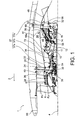
figure 1 représente une vue schématique en demi-coupe longitudinale d'un turboréacteur à double flux pour aéronef, selon un premier mode de réalisation préféré de la présente invention ; - la
figure 2 représente une vue partielle en coupe détaillant les moyens structuraux de rigidification du carter central du turboréacteur montré sur la figure précédente ; - la
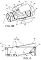
figure 3a représente une vue en perspective de moyens formant enveloppe délimitant intérieurement la veine secondaire du turboréacteur montré sur lafigure 1 ; - la
figure 3b représente une vue éclatée de celle de lafigure 3a ; et - les
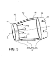
figures 4 et5 montrent des vues respectivement similaires à celles desfigures 2 et 3a , avec le turboréacteur se présentant sous la forme d'un second mode de réalisation préféré de la présente invention. - En référence tout d'abord à la
figure 1 , on peut apercevoir un turboréacteur d'aéronef 1 selon un premier mode de réalisation préféré. Dans toute la description qui va suivre, les termes « avant » et « arrière » sont à considérer par rapport à une direction d'avancement de l'aéronef provoquée par la poussée du turboréacteur, cette direction étant représentée schématiquement par la flèche 2. D'autre part, les termes « amont » et « aval » sont à considérer par rapport à une direction d'écoulement principale des gaz au sein du turboréacteur, contraire à la direction d'avancement 2 de l'aéronef. - Le turboréacteur 1, d'axe longitudinal 4, comporte d'amont en aval une soufflante 6, un compresseur basse pression 8, un compresseur haute pression 10, une chambre annulaire de combustion 12, une turbine haute pression 14 et une turbine basse pression 16. Les compresseurs, les turbines et la chambre de combustion constituent le générateur des gaz, qui est fermé en partie par un carter central 18 centré sur l'axe 4, et qui est traversé par un flux primaire Fp du turboréacteur.
- Le compresseur haute pression 10 est ici centrifuge, et comprend donc un rouet centrifuge qui permet, au droit d'une extrémité aval de ce rouet, d'éloigner radialement au maximum le carter central 18 de l'axe 4. Il en découle la présence d'une partie 18a du carter central, située au droit d'une zone de jonction 11 entre le rouet centrifuge et la chambre de combustion 12, qui se trouve donc éloignée radialement de l'axe 4, en saillie vers l'extérieur par rapport à ses parties adjacentes amont et aval.
- Ce carter central 18 prolonge vers l'arrière un carter intermédiaire 20 équipé d'une virole intérieure 22 et d'une virole extérieure 24 concentriques, entre lesquelles sont agencés des bras structuraux 26 qui les relient. La virole extérieure 24 se situe dans le prolongement aérodynamique arrière du carter de soufflante 28, tandis que la virole intérieure 22 se situe radialement vers l'extérieur par rapport à l'extrémité avant du carter central 18, fixée sur un moyeu 30 du carter intermédiaire.
- En outre, l'extrémité arrière du carter central 18 est prolongée par un carter d'échappement 32 situé en aval de la turbine basse pression 16.
- L'ensemble des carters précités sont fixés les uns aux autres, afin de former conjointement une structure à travers laquelle transitent des efforts statiques et dynamiques.
- Des premiers moyens 36 formant enveloppe sont agencés dans le prolongement aérodynamique arrière de la virole intérieure 22, en étant disposés autour du carter central 18. Ces moyens, dénommés en anglais « Inner Fan Duct », présentent extérieurement une surface annulaire 37 de délimitation interne d'une veine secondaire annulaire 38, traversée par le flux secondaire Fs du turboréacteur. La surface 37 se situe dans le prolongement aérodynamique arrière d'une autre surface 39 servant également à la délimitation interne de la veine secondaire annulaire 38, cette surface 39 étant définie par la virole intérieure 22. En outre, en aval de la surface 37 se trouve un mélangeur 48 dont la fonction connue réside dans le mélange des flux primaire Fp et secondaire Fs.
- L'espace annulaire 46 laissé libre entre le carter central 18 et les premiers moyens formant enveloppe remplit la fonction de compartiment, dit « compartiment Core », dans lequel sont agencés des équipements.
- Des seconds moyens 41 formant enveloppe sont agencés concentriquement et extérieurement aux premiers moyens 36 précités, dans le prolongement aérodynamique arrière de la virole extérieure 24. Ces moyens, dénommés en anglais « Outer Fan Duct », présentent intérieurement une surface annulaire 42 de délimitation externe de la veine 38. La surface 42 se situe dans le prolongement aérodynamique arrière d'une' autre surface 43 servant également à la délimitation externe de la veine secondaire annulaire 38, cette surface 43 étant définie par la virole extérieure 24. Ces seconds moyens formant enveloppe sont de préférence fixés à la nacelle 50. De plus, ils sont reliés au carter d'échappement 32 par une pluralité de bielles 52 reliées à ce dernier, agencées dans un plan transversal du turboréacteur et traversant lesdits premiers moyens 36 formant enveloppe, dont la liaison avec le mélangeur 48 se situe en aval de ces bielles 52.
- Pour ce qui concerne les premiers moyens 36 formant enveloppe, ils se décomposent en trois parties adjacentes axialement, la première étant une virole amont structurale 54, la seconde une enveloppe principale 56 de préférence non-structurale, et la troisième un anneau 58 de jonction aérodynamique entre l'enveloppe principale 56 et le mélangeur 48.
- En référence à présent aux
figures 1 à 3b , la virole structurale amont 54, de préférence métallique, s'étend sensiblement parallèlement à l'axe 4 sur lequel elle est centrée. Son extrémité avant est fixée par bride sur l'extrémité arrière de la virole intérieure 22 du carter intermédiaire, de manière à ce que la surface aérodynamique 39 se situe dans la continuité avant de la partie avant 37a de la surface de délimitation interne 37 de la veine secondaire annulaire 38. - Son extrémité arrière est quant à elle fixée à l'extrémité avant de l'enveloppe principale 56, de manière à ce que la surface aérodynamique 37a se situe dans la continuité avant de la partie principale 37b de la surface de délimitation interne 37, définie par l'enveloppe 56.
- En outre, l'anneau 58 de jonction aérodynamique entre l'enveloppe principale 56 et le mélangeur 48 présente une extrémité avant fixée sur l'extrémité arrière de l'enveloppe principale 56, de manière à ce que la surface aérodynamique 37b se situe dans la continuité avant de la partie arrière 37c de la surface de délimitation interne 37, définie par cet anneau 58. L'anneau 58 présente des échancrures 59 permettant le passage des bielles 52 qui le traversent, afin de relier le carter d'échappement 32 aux seconds moyens 41 formant enveloppe extérieure.
- Ainsi, les surfaces aérodynamiques 39, 37a, 37b, 37c forment conjointement une surface continue de délimitation interne du flux secondaire Fs.
- En référence plus particulièrement aux
figures 3a et3b , on peut apercevoir que l'enveloppe principale 56 comporte une pluralité de panneaux aérodynamiques 60 ainsi que des longerons de support 62 portant les panneaux 60. Les longerons 62 sont par exemple au nombre de quatre, répartis à 90°, et s'étendant chacun entre une extrémité avant montée fixement sur l'extrémité arrière de la virole amont structurale 54, et une extrémité arrière montée sur un anneau de support 66 centré sur l'axe 4. Ce support se trouve autour et à proximité d'une jonction entre le carter central 18 et le carter d'échappement 32, en y étant relié par des moyens conventionnels, par exemple du type épingles, montrés schématiquement et référencés 68 sur lafigure 1 . - Chaque panneau 60 se trouve alors supporté et fixé par deux longerons 62 directement consécutifs, respectivement au niveau de ses deux extrémités circonférentielles. Ses extrémités amont et aval se trouvent quant à elles dans la continuité aérodynamique de la virole amont structurale 54 et de l'anneau 58, respectivement. De plus, ces panneaux 60, qui forment la surface aérodynamique 37b conjointement avec les parties non-recouvertes des longerons 62, sont préférentiellement traités de manière acoustique, et présentent des trous d'homme 70 pour l'accès aux équipements du compartiment 46. A cet égard, il est indiqué que des trous d'homme peuvent également être prévus sur les longerons 62.
- L'une des particularités de la présente invention réside dans le fait que le turboréacteur comporte également des moyens structuraux de rigidification du carter central, ces moyens prenant ici la forme d'une structure annulaire ajourée 72. Cette structure 72 en forme de virole, qui s'étend sensiblement parallèlement à l'axe 4, est agencée dans le prolongement arrière de la virole amont structurale 54. Comme cela est visible sur la
figure 2 , son extrémité avant est en effet montée fixement par brides boulonnées sur l'extrémité arrière de la virole amont structurale 54, au même titre que l'enveloppe principale 56 qui l'entoure. Ainsi, la conception proposée est telle que la virole amont structurale 54, remplissant des fonctions aérodynamique et mécanique, se scinde vers l'arrière en une enveloppe principale 56 assurant la continuité de la fonction aérodynamique, et en une structure annulaire 72 assurant la continuité de la fonction mécanique. - La structure 72 s'étend vers l'arrière selon un diamètre sensiblement constant et identique à celui de la virole amont structurale 54, jusqu'à son extrémité arrière montée fixement par boulons sur la partie annulaire 18a du carter central, située au droit de la zone de jonction 11 entre le rouet centrifuge du compresseur haute pression 10 et la chambre de combustion 12. Cette structure annulaire 72 de rigidification se trouve donc à une distance radiale importante de l'axe 4, lui permettant de n'être que faiblement sollicitée thermiquement.
- Des ajours 74 en forme de trous d'homme peuvent être pratiqués sur cette structure, toujours de manière à favoriser l'accès aux équipements du compartiment 46.
- Avec cette conception, des efforts importants peuvent transiter successivement à travers le moyeu 30, la virole amont structurale 54, la structure annulaire 72 de rigidification, et le carter central 18, offrant ainsi au carter central une résistance mécanique à la flexion élevée.
- Selon un second mode de réalisation préféré montré sur les
figures 4 et5 , la seule modification apportée par rapport au premier mode décrit ci-dessus réside dans la conception des moyens structuraux de rigidification, qui prennent ici la forme d'une pluralité de bielles 172 espacées circonférentiellement les unes des autres, et chacune sensiblement parallèle à l'axe 4. - Bien entendu, diverses modifications peuvent être apportées par l'homme du métier à l'invention qui vient d'être décrite, uniquement à titre d'exemples non limitatifs.
Claims (7)
- Turbomachine à double flux (1) pour aéronef comprenant :- un carter intermédiaire (20) comportant une virole intérieure (22) et une virole extérieure (24) entre lesquelles sont agencés des bras structuraux (26), la virole intérieure présentant une première surface (39) de délimitation interne d'une veine secondaire annulaire (38) ;- un carter central (18) prolongeant ledit carter intermédiaire vers l'arrière ; et- des moyens (36) formant enveloppe agencés dans le prolongement arrière de ladite virole intérieure (22) du carter intermédiaire et disposés autour dudit carter central (18), ces moyens (36) présentant une seconde surface (37) de délimitation interne de la veine secondaire annulaire se situant dans le prolongement arrière de ladite première surface (39) de délimitation interne,lesdits moyens (36) formant enveloppe comportent d'une part une virole amont structurale (54) montée sur la virole intérieure (22) du carter intermédiaire et définissant la partie avant (37a) de la seconde surface de délimitation interne (37), et d'autre part une enveloppe principale (56) prolongeant vers l'arrière ladite virole amont (54),
caractérisée en ce que en ce que ladite turbomachine comporte en outre des moyens structuraux (72, 172) de rigidification du carter central, entourés par ladite enveloppe principale (56), et s'étendant vers l'arrière entre la virole amont (54) et le carter central (18) sur lesquels ces moyens (72, 172) sont montés. - Turbomachine selon la revendication 1, caractérisée en ce que lesdits moyens structuraux de rigidification du carter central prennent la forme d'une structure annulaire ajourée (72).
- Turbomachine selon la revendication 1, caractérisée en ce que lesdits moyens structuraux de rigidification du carter central prennent la forme d'une pluralité de bielles (172) espacées circonférentiellement les unes des autres.
- Turbomachine selon l'une quelconque des revendications précédentes, caractérisée en ce que lesdits moyens structuraux de rigidification du carter central s'étendent sensiblement parallèlement à l'axe longitudinal (4) de la turbomachine.
- Turbomachine selon l'une quelconque des revendications précédentes, caractérisée en ce que ladite enveloppe principale (56) comporte une pluralité de panneaux aérodynamiques (60) montés sur des longerons de support (62) rapportés à leur extrémité avant sur ladite virole amont structurale (54), et à leur extrémité arrière sur un anneau de support (66) se trouvant à proximité d'une jonction entre ledit carter central (18) et un carter d'échappement (32) le prolongeant vers l'arrière.
- Turbomachine selon l'une quelconque des revendications précédentes, caractérisée en ce que lesdits moyens structuraux (72, 172) de rigidification du carter central sont montés sur une partie (18a) de celui-ci située au droit d'une zone de jonction (11) entre un compresseur (10) et une chambre de combustion (12) de la turbomachine.
- Turbomachine selon l'une quelconque des revendications précédentes, caractérisée en ce qu'elle comprend un compresseur haute pression (10) centrifuge.
Applications Claiming Priority (2)
| Application Number | Priority Date | Filing Date | Title |
|---|---|---|---|
| FR0957800A FR2952126B1 (fr) | 2009-11-04 | 2009-11-04 | Turbomachine a double flux pour aeronef, comprenant des moyens structuraux de rigidification du carter central |
| PCT/EP2010/066609 WO2011054806A1 (fr) | 2009-11-04 | 2010-11-02 | Turbomachine a double flux pour aeronef, comprenant des moyens structuraux de rigidification du carter central |
Publications (2)
| Publication Number | Publication Date |
|---|---|
| EP2496795A1 EP2496795A1 (fr) | 2012-09-12 |
| EP2496795B1 true EP2496795B1 (fr) | 2015-04-01 |
Family
ID=42244557
Family Applications (1)
| Application Number | Title | Priority Date | Filing Date |
|---|---|---|---|
| EP10771484.2A Active EP2496795B1 (fr) | 2009-11-04 | 2010-11-02 | Turbomachine a double flux pour aeronef, comprenant des moyens structuraux de rigidification du carter central |
Country Status (8)
| Country | Link |
|---|---|
| US (1) | US9157334B2 (fr) |
| EP (1) | EP2496795B1 (fr) |
| CN (1) | CN102667072A (fr) |
| BR (1) | BR112012010291A2 (fr) |
| CA (1) | CA2779253A1 (fr) |
| FR (1) | FR2952126B1 (fr) |
| RU (1) | RU2012122037A (fr) |
| WO (1) | WO2011054806A1 (fr) |
Families Citing this family (8)
| Publication number | Priority date | Publication date | Assignee | Title |
|---|---|---|---|---|
| FR2981686B1 (fr) * | 2011-10-21 | 2016-05-20 | Snecma | Turbomachine comprenant un recepteur a helices contrarotatives supporte par une enveloppe structurale fixee au carter intermediaire |
| FR3010147B1 (fr) | 2013-08-28 | 2015-08-21 | Snecma | Suspension isostatique d'un turboreacteur par double support arriere |
| US9784129B2 (en) * | 2014-08-01 | 2017-10-10 | Pratt & Whitney Canada Corp. | Rear mount assembly for gas turbine engine |
| GB201806564D0 (en) | 2018-04-23 | 2018-06-06 | Rolls Royce Plc | Gas turbine engine inner barrel |
| GB201806563D0 (en) | 2018-04-23 | 2018-06-06 | Rolls Royce Plc | Gas turbine engine keel beam |
| US12617541B1 (en) | 2024-12-19 | 2026-05-05 | Pratt & Whitney Canada Corp. | Exhaust case for aircraft engine |
| US12618342B1 (en) | 2025-05-07 | 2026-05-05 | Pratt & Whitney Canada Corp. | Turbine exhaust case with stiffening brace |
| US12529325B1 (en) | 2025-07-29 | 2026-01-20 | Pratt & Whitney Canada Corp. | Turbine exhaust duct with stiffeners for aircraft engines |
Family Cites Families (14)
| Publication number | Priority date | Publication date | Assignee | Title |
|---|---|---|---|---|
| JP4375883B2 (ja) * | 2000-06-02 | 2009-12-02 | 本田技研工業株式会社 | ガスタービンエンジンの軸受へのシールエア供給装置 |
| US6488469B1 (en) | 2000-10-06 | 2002-12-03 | Pratt & Whitney Canada Corp. | Mixed flow and centrifugal compressor for gas turbine engine |
| US7370467B2 (en) * | 2003-07-29 | 2008-05-13 | Pratt & Whitney Canada Corp. | Turbofan case and method of making |
| FR2866070B1 (fr) * | 2004-02-05 | 2008-12-05 | Snecma Moteurs | Turboreacteur a fort taux de dilution |
| FR2867158B1 (fr) * | 2004-03-04 | 2007-06-08 | Airbus France | Systeme de montage interpose entre un moteur d'aeronef et une structure rigide d'un mat d'accrochage fixe sous une voilure de cet aeronef. |
| GB0520850D0 (en) * | 2005-10-14 | 2005-11-23 | Rolls Royce Plc | Fan static structure |
| US7363762B2 (en) * | 2005-11-16 | 2008-04-29 | General Electric Company | Gas turbine engines seal assembly and methods of assembling the same |
| FR2904048B1 (fr) * | 2006-07-19 | 2012-12-14 | Snecma | Systeme de ventilation de paroi de chambre de combustion dans une turbomachine |
| US7908869B2 (en) * | 2006-09-18 | 2011-03-22 | Pratt & Whitney Canada Corp. | Thermal and external load isolating impeller shroud |
| FR2905975B1 (fr) * | 2006-09-20 | 2008-12-05 | Snecma Sa | Conduite de soufflante pour une turbomachine. |
| FR2907098B1 (fr) * | 2006-10-11 | 2010-04-16 | Aircelle Sa | Nacelle pour turboreacteur double flux |
| FR2919347B1 (fr) * | 2007-07-26 | 2009-11-20 | Snecma | Enveloppe externe de conduite de soufflante dans une turbomachine. |
| US8438859B2 (en) * | 2008-01-08 | 2013-05-14 | Rolls-Royce North American Technologies, Inc. | Integrated bypass engine structure |
| FR2932227B1 (fr) * | 2008-06-09 | 2011-07-01 | Snecma | Turboreacteur double flux |
-
2009
- 2009-11-04 FR FR0957800A patent/FR2952126B1/fr not_active Expired - Fee Related
-
2010
- 2010-11-02 BR BR112012010291A patent/BR112012010291A2/pt not_active IP Right Cessation
- 2010-11-02 WO PCT/EP2010/066609 patent/WO2011054806A1/fr not_active Ceased
- 2010-11-02 US US13/504,009 patent/US9157334B2/en active Active
- 2010-11-02 EP EP10771484.2A patent/EP2496795B1/fr active Active
- 2010-11-02 CN CN2010800483774A patent/CN102667072A/zh active Pending
- 2010-11-02 RU RU2012122037/06A patent/RU2012122037A/ru not_active Application Discontinuation
- 2010-11-02 CA CA2779253A patent/CA2779253A1/fr not_active Abandoned
Also Published As
| Publication number | Publication date |
|---|---|
| US9157334B2 (en) | 2015-10-13 |
| EP2496795A1 (fr) | 2012-09-12 |
| US20130195640A1 (en) | 2013-08-01 |
| RU2012122037A (ru) | 2013-12-10 |
| BR112012010291A2 (pt) | 2017-07-04 |
| CN102667072A (zh) | 2012-09-12 |
| CA2779253A1 (fr) | 2011-05-12 |
| FR2952126A1 (fr) | 2011-05-06 |
| FR2952126B1 (fr) | 2011-12-23 |
| WO2011054806A1 (fr) | 2011-05-12 |
Similar Documents
| Publication | Publication Date | Title |
|---|---|---|
| EP2300690B1 (fr) | Carter structural pour turbomachine | |
| CA2637647C (fr) | Enveloppe externe de conduite de soufflante dans une turbomachine | |
| EP2288542B1 (fr) | Système propulsif d'aéronef | |
| WO2011054806A1 (fr) | Turbomachine a double flux pour aeronef, comprenant des moyens structuraux de rigidification du carter central | |
| FR3132743A1 (fr) | Ensemble de turbomachine comprenant un carter | |
| EP0761931A1 (fr) | Agencement de turbomachine comprenant une grille d'aubes et un carter intermédiaire | |
| FR2601069A1 (fr) | Turbine. | |
| CA2928696C (fr) | Turbomachine equipee de moyens de reprise des efforts de poussee de son moteur | |
| FR2981686A1 (fr) | Turbomachine comprenant un recepteur a helices contrarotatives supporte par une enveloppe structurale fixee au carter intermediaire | |
| WO2010122053A1 (fr) | Carter intermediaire de turbomachine d'aeronef comprenant des bras structuraux de raccord a fonctions mecanique et aerodynamique dissociees | |
| FR2969700A1 (fr) | Systeme propulsif pour aeronef | |
| WO2022069835A1 (fr) | Module de turbomachine equipe d'une helice et d'aubes de stator deportees | |
| EP3810903B1 (fr) | Virole extérieure de turbomachine | |
| BE1024605B1 (fr) | Carter avec bras aspirant pour turbomachine axiale | |
| WO2022096832A1 (fr) | Fixation d'un cône d'éjection dans une turbine de turbomachine | |
| FR2969714A1 (fr) | Recepteur de turbomachine d'aeronef a doublet d'helices contrarotatives non carenees, comprenant une turbine libre exterieure a maintien renforce | |
| FR3115833A1 (fr) | Fixation d’un cône d’éjection dans une turbine de turbomachine | |
| BE1026199B1 (fr) | Virole exterieure en deux parties | |
| EP4323631B1 (fr) | Inverseur de poussee a grilles mobiles comprenant une structure fixe plurifonctionnelle | |
| CA2780548A1 (fr) | Structure annulaire metallique de raccord pour turbomachine d'aeronef | |
| WO2025078775A1 (fr) | Tuyere d'ejection de flux d'air a structure interne demontable et turbomachine equipee d'une telle tuyere | |
| FR3135748A1 (fr) | Ensemble propulsif pour un aeronef | |
| FR3135747A1 (fr) | Ensemble propulsif pour un aeronef | |
| FR3135749A1 (fr) | Ensemble propulsif pour un aeronef | |
| FR3135746A1 (fr) | Ensemble propulsif pour un aeronef |
Legal Events
| Date | Code | Title | Description |
|---|---|---|---|
| PUAI | Public reference made under article 153(3) epc to a published international application that has entered the european phase |
Free format text: ORIGINAL CODE: 0009012 |
|
| 17P | Request for examination filed |
Effective date: 20120502 |
|
| AK | Designated contracting states |
Kind code of ref document: A1 Designated state(s): AL AT BE BG CH CY CZ DE DK EE ES FI FR GB GR HR HU IE IS IT LI LT LU LV MC MK MT NL NO PL PT RO RS SE SI SK SM TR |
|
| RIN1 | Information on inventor provided before grant (corrected) |
Inventor name: AU QUANG, AUDREY Inventor name: DERENES, JACKY, RAPHAEL, MICHEL Inventor name: SEIZE, GUILHEM Inventor name: REAUX, CLARISSE, SAVINE, MATHILDE |
|
| RIN1 | Information on inventor provided before grant (corrected) |
Inventor name: DERENES, JACKY, RAPHAEL, MICHEL Inventor name: REAUX, CLARISSE, SAVINE, MATHILDE Inventor name: GREDE, AUDREY Inventor name: SEIZE, GUILHEM |
|
| DAX | Request for extension of the european patent (deleted) | ||
| GRAP | Despatch of communication of intention to grant a patent |
Free format text: ORIGINAL CODE: EPIDOSNIGR1 |
|
| INTG | Intention to grant announced |
Effective date: 20141027 |
|
| GRAS | Grant fee paid |
Free format text: ORIGINAL CODE: EPIDOSNIGR3 |
|
| GRAA | (expected) grant |
Free format text: ORIGINAL CODE: 0009210 |
|
| AK | Designated contracting states |
Kind code of ref document: B1 Designated state(s): AL AT BE BG CH CY CZ DE DK EE ES FI FR GB GR HR HU IE IS IT LI LT LU LV MC MK MT NL NO PL PT RO RS SE SI SK SM TR |
|
| REG | Reference to a national code |
Ref country code: GB Ref legal event code: FG4D Free format text: NOT ENGLISH |
|
| REG | Reference to a national code |
Ref country code: CH Ref legal event code: EP |
|
| REG | Reference to a national code |
Ref country code: IE Ref legal event code: FG4D Free format text: LANGUAGE OF EP DOCUMENT: FRENCH |
|
| REG | Reference to a national code |
Ref country code: DE Ref legal event code: R096 Ref document number: 602010023622 Country of ref document: DE Effective date: 20150513 |
|
| REG | Reference to a national code |
Ref country code: AT Ref legal event code: REF Ref document number: 719217 Country of ref document: AT Kind code of ref document: T Effective date: 20150515 |
|
| REG | Reference to a national code |
Ref country code: SE Ref legal event code: TRGR |
|
| REG | Reference to a national code |
Ref country code: NL Ref legal event code: VDEP Effective date: 20150401 |
|
| REG | Reference to a national code |
Ref country code: AT Ref legal event code: MK05 Ref document number: 719217 Country of ref document: AT Kind code of ref document: T Effective date: 20150401 |
|
| REG | Reference to a national code |
Ref country code: LT Ref legal event code: MG4D |
|
| PG25 | Lapsed in a contracting state [announced via postgrant information from national office to epo] |
Ref country code: NL Free format text: LAPSE BECAUSE OF FAILURE TO SUBMIT A TRANSLATION OF THE DESCRIPTION OR TO PAY THE FEE WITHIN THE PRESCRIBED TIME-LIMIT Effective date: 20150401 |
|
| PG25 | Lapsed in a contracting state [announced via postgrant information from national office to epo] |
Ref country code: HR Free format text: LAPSE BECAUSE OF FAILURE TO SUBMIT A TRANSLATION OF THE DESCRIPTION OR TO PAY THE FEE WITHIN THE PRESCRIBED TIME-LIMIT Effective date: 20150401 Ref country code: LT Free format text: LAPSE BECAUSE OF FAILURE TO SUBMIT A TRANSLATION OF THE DESCRIPTION OR TO PAY THE FEE WITHIN THE PRESCRIBED TIME-LIMIT Effective date: 20150401 Ref country code: FI Free format text: LAPSE BECAUSE OF FAILURE TO SUBMIT A TRANSLATION OF THE DESCRIPTION OR TO PAY THE FEE WITHIN THE PRESCRIBED TIME-LIMIT Effective date: 20150401 Ref country code: CZ Free format text: LAPSE BECAUSE OF FAILURE TO SUBMIT A TRANSLATION OF THE DESCRIPTION OR TO PAY THE FEE WITHIN THE PRESCRIBED TIME-LIMIT Effective date: 20150401 Ref country code: NO Free format text: LAPSE BECAUSE OF FAILURE TO SUBMIT A TRANSLATION OF THE DESCRIPTION OR TO PAY THE FEE WITHIN THE PRESCRIBED TIME-LIMIT Effective date: 20150701 Ref country code: PT Free format text: LAPSE BECAUSE OF FAILURE TO SUBMIT A TRANSLATION OF THE DESCRIPTION OR TO PAY THE FEE WITHIN THE PRESCRIBED TIME-LIMIT Effective date: 20150803 Ref country code: ES Free format text: LAPSE BECAUSE OF FAILURE TO SUBMIT A TRANSLATION OF THE DESCRIPTION OR TO PAY THE FEE WITHIN THE PRESCRIBED TIME-LIMIT Effective date: 20150401 |
|
| REG | Reference to a national code |
Ref country code: FR Ref legal event code: PLFP Year of fee payment: 6 |
|
| PG25 | Lapsed in a contracting state [announced via postgrant information from national office to epo] |
Ref country code: GR Free format text: LAPSE BECAUSE OF FAILURE TO SUBMIT A TRANSLATION OF THE DESCRIPTION OR TO PAY THE FEE WITHIN THE PRESCRIBED TIME-LIMIT Effective date: 20150702 Ref country code: IS Free format text: LAPSE BECAUSE OF FAILURE TO SUBMIT A TRANSLATION OF THE DESCRIPTION OR TO PAY THE FEE WITHIN THE PRESCRIBED TIME-LIMIT Effective date: 20150801 Ref country code: RS Free format text: LAPSE BECAUSE OF FAILURE TO SUBMIT A TRANSLATION OF THE DESCRIPTION OR TO PAY THE FEE WITHIN THE PRESCRIBED TIME-LIMIT Effective date: 20150401 Ref country code: AT Free format text: LAPSE BECAUSE OF FAILURE TO SUBMIT A TRANSLATION OF THE DESCRIPTION OR TO PAY THE FEE WITHIN THE PRESCRIBED TIME-LIMIT Effective date: 20150401 Ref country code: LV Free format text: LAPSE BECAUSE OF FAILURE TO SUBMIT A TRANSLATION OF THE DESCRIPTION OR TO PAY THE FEE WITHIN THE PRESCRIBED TIME-LIMIT Effective date: 20150401 |
|
| REG | Reference to a national code |
Ref country code: DE Ref legal event code: R097 Ref document number: 602010023622 Country of ref document: DE |
|
| PG25 | Lapsed in a contracting state [announced via postgrant information from national office to epo] |
Ref country code: DK Free format text: LAPSE BECAUSE OF FAILURE TO SUBMIT A TRANSLATION OF THE DESCRIPTION OR TO PAY THE FEE WITHIN THE PRESCRIBED TIME-LIMIT Effective date: 20150401 Ref country code: EE Free format text: LAPSE BECAUSE OF FAILURE TO SUBMIT A TRANSLATION OF THE DESCRIPTION OR TO PAY THE FEE WITHIN THE PRESCRIBED TIME-LIMIT Effective date: 20150401 |
|
| PLBE | No opposition filed within time limit |
Free format text: ORIGINAL CODE: 0009261 |
|
| STAA | Information on the status of an ep patent application or granted ep patent |
Free format text: STATUS: NO OPPOSITION FILED WITHIN TIME LIMIT |
|
| PG25 | Lapsed in a contracting state [announced via postgrant information from national office to epo] |
Ref country code: PL Free format text: LAPSE BECAUSE OF FAILURE TO SUBMIT A TRANSLATION OF THE DESCRIPTION OR TO PAY THE FEE WITHIN THE PRESCRIBED TIME-LIMIT Effective date: 20150401 Ref country code: SK Free format text: LAPSE BECAUSE OF FAILURE TO SUBMIT A TRANSLATION OF THE DESCRIPTION OR TO PAY THE FEE WITHIN THE PRESCRIBED TIME-LIMIT Effective date: 20150401 Ref country code: RO Free format text: LAPSE BECAUSE OF NON-PAYMENT OF DUE FEES Effective date: 20150401 |
|
| 26N | No opposition filed |
Effective date: 20160105 |
|
| PG25 | Lapsed in a contracting state [announced via postgrant information from national office to epo] |
Ref country code: SI Free format text: LAPSE BECAUSE OF FAILURE TO SUBMIT A TRANSLATION OF THE DESCRIPTION OR TO PAY THE FEE WITHIN THE PRESCRIBED TIME-LIMIT Effective date: 20150401 |
|
| REG | Reference to a national code |
Ref country code: DE Ref legal event code: R119 Ref document number: 602010023622 Country of ref document: DE |
|
| PG25 | Lapsed in a contracting state [announced via postgrant information from national office to epo] |
Ref country code: MC Free format text: LAPSE BECAUSE OF FAILURE TO SUBMIT A TRANSLATION OF THE DESCRIPTION OR TO PAY THE FEE WITHIN THE PRESCRIBED TIME-LIMIT Effective date: 20150401 Ref country code: LU Free format text: LAPSE BECAUSE OF FAILURE TO SUBMIT A TRANSLATION OF THE DESCRIPTION OR TO PAY THE FEE WITHIN THE PRESCRIBED TIME-LIMIT Effective date: 20151102 |
|
| REG | Reference to a national code |
Ref country code: CH Ref legal event code: PL |
|
| PG25 | Lapsed in a contracting state [announced via postgrant information from national office to epo] |
Ref country code: LI Free format text: LAPSE BECAUSE OF NON-PAYMENT OF DUE FEES Effective date: 20151130 Ref country code: CH Free format text: LAPSE BECAUSE OF NON-PAYMENT OF DUE FEES Effective date: 20151130 |
|
| REG | Reference to a national code |
Ref country code: IE Ref legal event code: MM4A |
|
| PG25 | Lapsed in a contracting state [announced via postgrant information from national office to epo] |
Ref country code: SE Free format text: LAPSE BECAUSE OF NON-PAYMENT OF DUE FEES Effective date: 20151103 |
|
| PG25 | Lapsed in a contracting state [announced via postgrant information from national office to epo] |
Ref country code: IE Free format text: LAPSE BECAUSE OF NON-PAYMENT OF DUE FEES Effective date: 20151102 Ref country code: DE Free format text: LAPSE BECAUSE OF NON-PAYMENT OF DUE FEES Effective date: 20160601 |
|
| REG | Reference to a national code |
Ref country code: FR Ref legal event code: PLFP Year of fee payment: 7 |
|
| PG25 | Lapsed in a contracting state [announced via postgrant information from national office to epo] |
Ref country code: IT Free format text: LAPSE BECAUSE OF NON-PAYMENT OF DUE FEES Effective date: 20151102 |
|
| PG25 | Lapsed in a contracting state [announced via postgrant information from national office to epo] |
Ref country code: HU Free format text: LAPSE BECAUSE OF FAILURE TO SUBMIT A TRANSLATION OF THE DESCRIPTION OR TO PAY THE FEE WITHIN THE PRESCRIBED TIME-LIMIT; INVALID AB INITIO Effective date: 20101102 Ref country code: SM Free format text: LAPSE BECAUSE OF FAILURE TO SUBMIT A TRANSLATION OF THE DESCRIPTION OR TO PAY THE FEE WITHIN THE PRESCRIBED TIME-LIMIT Effective date: 20150401 Ref country code: BG Free format text: LAPSE BECAUSE OF FAILURE TO SUBMIT A TRANSLATION OF THE DESCRIPTION OR TO PAY THE FEE WITHIN THE PRESCRIBED TIME-LIMIT Effective date: 20150401 |
|
| PG25 | Lapsed in a contracting state [announced via postgrant information from national office to epo] |
Ref country code: CY Free format text: LAPSE BECAUSE OF FAILURE TO SUBMIT A TRANSLATION OF THE DESCRIPTION OR TO PAY THE FEE WITHIN THE PRESCRIBED TIME-LIMIT Effective date: 20150401 |
|
| PG25 | Lapsed in a contracting state [announced via postgrant information from national office to epo] |
Ref country code: BE Free format text: LAPSE BECAUSE OF NON-PAYMENT OF DUE FEES Effective date: 20151130 |
|
| PG25 | Lapsed in a contracting state [announced via postgrant information from national office to epo] |
Ref country code: TR Free format text: LAPSE BECAUSE OF FAILURE TO SUBMIT A TRANSLATION OF THE DESCRIPTION OR TO PAY THE FEE WITHIN THE PRESCRIBED TIME-LIMIT Effective date: 20150401 Ref country code: MT Free format text: LAPSE BECAUSE OF FAILURE TO SUBMIT A TRANSLATION OF THE DESCRIPTION OR TO PAY THE FEE WITHIN THE PRESCRIBED TIME-LIMIT Effective date: 20150401 |
|
| REG | Reference to a national code |
Ref country code: FR Ref legal event code: PLFP Year of fee payment: 8 |
|
| PG25 | Lapsed in a contracting state [announced via postgrant information from national office to epo] |
Ref country code: MK Free format text: LAPSE BECAUSE OF FAILURE TO SUBMIT A TRANSLATION OF THE DESCRIPTION OR TO PAY THE FEE WITHIN THE PRESCRIBED TIME-LIMIT Effective date: 20150401 |
|
| REG | Reference to a national code |
Ref country code: FR Ref legal event code: CD Owner name: SAFRAN AIRCRAFT ENGINES, FR Effective date: 20170719 |
|
| REG | Reference to a national code |
Ref country code: FR Ref legal event code: PLFP Year of fee payment: 9 |
|
| PG25 | Lapsed in a contracting state [announced via postgrant information from national office to epo] |
Ref country code: AL Free format text: LAPSE BECAUSE OF FAILURE TO SUBMIT A TRANSLATION OF THE DESCRIPTION OR TO PAY THE FEE WITHIN THE PRESCRIBED TIME-LIMIT Effective date: 20150401 |
|
| PGFP | Annual fee paid to national office [announced via postgrant information from national office to epo] |
Ref country code: GB Payment date: 20251125 Year of fee payment: 16 |
|
| PGFP | Annual fee paid to national office [announced via postgrant information from national office to epo] |
Ref country code: FR Payment date: 20251125 Year of fee payment: 16 |