EP2496531B1 - Simultaneous anoxic biological phosphorus and nitrogen removal - Google Patents
Simultaneous anoxic biological phosphorus and nitrogen removal Download PDFInfo
- Publication number
- EP2496531B1 EP2496531B1 EP11827190.7A EP11827190A EP2496531B1 EP 2496531 B1 EP2496531 B1 EP 2496531B1 EP 11827190 A EP11827190 A EP 11827190A EP 2496531 B1 EP2496531 B1 EP 2496531B1
- Authority
- EP
- European Patent Office
- Prior art keywords
- tank
- activated sludge
- phosphorus
- organic matter
- wastewater
- Prior art date
- Legal status (The legal status is an assumption and is not a legal conclusion. Google has not performed a legal analysis and makes no representation as to the accuracy of the status listed.)
- Not-in-force
Links
- OAICVXFJPJFONN-UHFFFAOYSA-N Phosphorus Chemical compound [P] OAICVXFJPJFONN-UHFFFAOYSA-N 0.000 title claims description 50
- 229910052698 phosphorus Inorganic materials 0.000 title claims description 50
- 239000011574 phosphorus Substances 0.000 title claims description 50
- IJGRMHOSHXDMSA-UHFFFAOYSA-N Atomic nitrogen Chemical compound N#N IJGRMHOSHXDMSA-UHFFFAOYSA-N 0.000 title claims description 33
- 229910052757 nitrogen Inorganic materials 0.000 title claims description 12
- QVGXLLKOCUKJST-UHFFFAOYSA-N atomic oxygen Chemical compound [O] QVGXLLKOCUKJST-UHFFFAOYSA-N 0.000 claims description 50
- 239000001301 oxygen Substances 0.000 claims description 50
- 229910052760 oxygen Inorganic materials 0.000 claims description 50
- 239000010802 sludge Substances 0.000 claims description 46
- 238000000034 method Methods 0.000 claims description 42
- 230000008569 process Effects 0.000 claims description 38
- 239000012528 membrane Substances 0.000 claims description 29
- 239000002351 wastewater Substances 0.000 claims description 29
- 239000005416 organic matter Substances 0.000 claims description 20
- 150000002823 nitrates Chemical class 0.000 claims description 15
- 239000002846 particulate organic matter Substances 0.000 claims description 14
- XLYOFNOQVPJJNP-UHFFFAOYSA-N water Substances O XLYOFNOQVPJJNP-UHFFFAOYSA-N 0.000 claims description 12
- 229910001868 water Inorganic materials 0.000 claims description 12
- 150000002826 nitrites Chemical class 0.000 claims description 9
- 239000005446 dissolved organic matter Substances 0.000 claims description 8
- 238000000855 fermentation Methods 0.000 claims description 6
- 230000004151 fermentation Effects 0.000 claims description 6
- 238000002156 mixing Methods 0.000 claims description 3
- BHEPBYXIRTUNPN-UHFFFAOYSA-N hydridophosphorus(.) (triplet) Chemical compound [PH] BHEPBYXIRTUNPN-UHFFFAOYSA-N 0.000 claims description 2
- 244000005700 microbiome Species 0.000 claims description 2
- 230000000977 initiatory effect Effects 0.000 claims 1
- 238000006243 chemical reaction Methods 0.000 description 34
- QGZKDVFQNNGYKY-UHFFFAOYSA-N Ammonia Chemical compound N QGZKDVFQNNGYKY-UHFFFAOYSA-N 0.000 description 30
- OKTJSMMVPCPJKN-UHFFFAOYSA-N Carbon Chemical compound [C] OKTJSMMVPCPJKN-UHFFFAOYSA-N 0.000 description 30
- 229910052799 carbon Inorganic materials 0.000 description 30
- 238000004065 wastewater treatment Methods 0.000 description 18
- 229910002651 NO3 Inorganic materials 0.000 description 15
- 229910000069 nitrogen hydride Inorganic materials 0.000 description 15
- 241000894006 Bacteria Species 0.000 description 14
- 229910021529 ammonia Inorganic materials 0.000 description 14
- NHNBFGGVMKEFGY-UHFFFAOYSA-N Nitrate Chemical compound [O-][N+]([O-])=O NHNBFGGVMKEFGY-UHFFFAOYSA-N 0.000 description 12
- CURLTUGMZLYLDI-UHFFFAOYSA-N Carbon dioxide Chemical compound O=C=O CURLTUGMZLYLDI-UHFFFAOYSA-N 0.000 description 10
- OKKJLVBELUTLKV-UHFFFAOYSA-N Methanol Chemical compound OC OKKJLVBELUTLKV-UHFFFAOYSA-N 0.000 description 9
- 229910001873 dinitrogen Inorganic materials 0.000 description 8
- NBIIXXVUZAFLBC-UHFFFAOYSA-K phosphate Chemical compound [O-]P([O-])([O-])=O NBIIXXVUZAFLBC-UHFFFAOYSA-K 0.000 description 8
- 229910019142 PO4 Inorganic materials 0.000 description 7
- 235000021317 phosphate Nutrition 0.000 description 7
- 230000001580 bacterial effect Effects 0.000 description 6
- 229910002092 carbon dioxide Inorganic materials 0.000 description 6
- 230000007062 hydrolysis Effects 0.000 description 6
- 238000006460 hydrolysis reaction Methods 0.000 description 6
- 239000010452 phosphate Substances 0.000 description 6
- IOVCWXUNBOPUCH-UHFFFAOYSA-M Nitrite anion Chemical compound [O-]N=O IOVCWXUNBOPUCH-UHFFFAOYSA-M 0.000 description 5
- 230000003647 oxidation Effects 0.000 description 5
- 238000007254 oxidation reaction Methods 0.000 description 5
- 239000001569 carbon dioxide Substances 0.000 description 4
- 238000000926 separation method Methods 0.000 description 4
- 229920000388 Polyphosphate Polymers 0.000 description 3
- 230000001651 autotrophic effect Effects 0.000 description 3
- 230000015572 biosynthetic process Effects 0.000 description 3
- -1 carbon dioxide Chemical class 0.000 description 3
- 230000015556 catabolic process Effects 0.000 description 3
- 230000003247 decreasing effect Effects 0.000 description 3
- 230000012010 growth Effects 0.000 description 3
- 230000000813 microbial effect Effects 0.000 description 3
- 239000005014 poly(hydroxyalkanoate) Substances 0.000 description 3
- 229920000903 polyhydroxyalkanoate Polymers 0.000 description 3
- 239000001205 polyphosphate Substances 0.000 description 3
- 235000011176 polyphosphates Nutrition 0.000 description 3
- 239000002028 Biomass Substances 0.000 description 2
- 241001453382 Nitrosomonadales Species 0.000 description 2
- GQPLMRYTRLFLPF-UHFFFAOYSA-N Nitrous Oxide Chemical compound [O-][N+]#N GQPLMRYTRLFLPF-UHFFFAOYSA-N 0.000 description 2
- IOVCWXUNBOPUCH-UHFFFAOYSA-N Nitrous acid Chemical compound ON=O IOVCWXUNBOPUCH-UHFFFAOYSA-N 0.000 description 2
- 238000005516 engineering process Methods 0.000 description 2
- 239000007788 liquid Substances 0.000 description 2
- 238000004519 manufacturing process Methods 0.000 description 2
- 238000001471 micro-filtration Methods 0.000 description 2
- 230000033116 oxidation-reduction process Effects 0.000 description 2
- 230000009467 reduction Effects 0.000 description 2
- 239000007787 solid Substances 0.000 description 2
- 239000000126 substance Substances 0.000 description 2
- 238000003786 synthesis reaction Methods 0.000 description 2
- 238000000108 ultra-filtration Methods 0.000 description 2
- 239000002699 waste material Substances 0.000 description 2
- 241000203069 Archaea Species 0.000 description 1
- 241000233866 Fungi Species 0.000 description 1
- 241000605159 Nitrobacter Species 0.000 description 1
- 241000605122 Nitrosomonas Species 0.000 description 1
- 241000700141 Rotifera Species 0.000 description 1
- 238000005273 aeration Methods 0.000 description 1
- 150000001722 carbon compounds Chemical class 0.000 description 1
- 230000010261 cell growth Effects 0.000 description 1
- 150000001875 compounds Chemical class 0.000 description 1
- 239000000470 constituent Substances 0.000 description 1
- 238000009295 crossflow filtration Methods 0.000 description 1
- 230000006735 deficit Effects 0.000 description 1
- 230000001419 dependent effect Effects 0.000 description 1
- 239000003344 environmental pollutant Substances 0.000 description 1
- 239000008187 granular material Substances 0.000 description 1
- 239000012510 hollow fiber Substances 0.000 description 1
- 239000001257 hydrogen Substances 0.000 description 1
- 229910052739 hydrogen Inorganic materials 0.000 description 1
- 230000003834 intracellular effect Effects 0.000 description 1
- 230000014759 maintenance of location Effects 0.000 description 1
- 230000007246 mechanism Effects 0.000 description 1
- 238000005374 membrane filtration Methods 0.000 description 1
- VUZPPFZMUPKLLV-UHFFFAOYSA-N methane;hydrate Chemical compound C.O VUZPPFZMUPKLLV-UHFFFAOYSA-N 0.000 description 1
- 230000000696 methanogenic effect Effects 0.000 description 1
- 239000000203 mixture Substances 0.000 description 1
- 239000000178 monomer Substances 0.000 description 1
- 239000011368 organic material Substances 0.000 description 1
- 230000001590 oxidative effect Effects 0.000 description 1
- 230000036284 oxygen consumption Effects 0.000 description 1
- 239000002957 persistent organic pollutant Substances 0.000 description 1
- 150000003013 phosphoric acid derivatives Chemical class 0.000 description 1
- 231100000719 pollutant Toxicity 0.000 description 1
- 229920000642 polymer Polymers 0.000 description 1
- 238000006479 redox reaction Methods 0.000 description 1
- 230000004044 response Effects 0.000 description 1
- 238000009991 scouring Methods 0.000 description 1
- 238000011144 upstream manufacturing Methods 0.000 description 1
Images


Classifications
-
- C—CHEMISTRY; METALLURGY
- C02—TREATMENT OF WATER, WASTE WATER, SEWAGE, OR SLUDGE
- C02F—TREATMENT OF WATER, WASTE WATER, SEWAGE, OR SLUDGE
- C02F3/00—Biological treatment of water, waste water, or sewage
- C02F3/30—Aerobic and anaerobic processes
-
- C—CHEMISTRY; METALLURGY
- C02—TREATMENT OF WATER, WASTE WATER, SEWAGE, OR SLUDGE
- C02F—TREATMENT OF WATER, WASTE WATER, SEWAGE, OR SLUDGE
- C02F3/00—Biological treatment of water, waste water, or sewage
- C02F3/30—Aerobic and anaerobic processes
- C02F3/308—Biological phosphorus removal
-
- C—CHEMISTRY; METALLURGY
- C02—TREATMENT OF WATER, WASTE WATER, SEWAGE, OR SLUDGE
- C02F—TREATMENT OF WATER, WASTE WATER, SEWAGE, OR SLUDGE
- C02F3/00—Biological treatment of water, waste water, or sewage
- C02F3/02—Aerobic processes
- C02F3/12—Activated sludge processes
- C02F3/1236—Particular type of activated sludge installations
- C02F3/1268—Membrane bioreactor systems
-
- C—CHEMISTRY; METALLURGY
- C02—TREATMENT OF WATER, WASTE WATER, SEWAGE, OR SLUDGE
- C02F—TREATMENT OF WATER, WASTE WATER, SEWAGE, OR SLUDGE
- C02F3/00—Biological treatment of water, waste water, or sewage
- C02F3/02—Aerobic processes
- C02F3/12—Activated sludge processes
- C02F3/1236—Particular type of activated sludge installations
- C02F3/1268—Membrane bioreactor systems
- C02F3/1273—Submerged membrane bioreactors
-
- C—CHEMISTRY; METALLURGY
- C02—TREATMENT OF WATER, WASTE WATER, SEWAGE, OR SLUDGE
- C02F—TREATMENT OF WATER, WASTE WATER, SEWAGE, OR SLUDGE
- C02F3/00—Biological treatment of water, waste water, or sewage
- C02F3/30—Aerobic and anaerobic processes
- C02F3/302—Nitrification and denitrification treatment
-
- C—CHEMISTRY; METALLURGY
- C02—TREATMENT OF WATER, WASTE WATER, SEWAGE, OR SLUDGE
- C02F—TREATMENT OF WATER, WASTE WATER, SEWAGE, OR SLUDGE
- C02F3/00—Biological treatment of water, waste water, or sewage
- C02F3/34—Biological treatment of water, waste water, or sewage characterised by the microorganisms used
-
- C—CHEMISTRY; METALLURGY
- C02—TREATMENT OF WATER, WASTE WATER, SEWAGE, OR SLUDGE
- C02F—TREATMENT OF WATER, WASTE WATER, SEWAGE, OR SLUDGE
- C02F2101/00—Nature of the contaminant
- C02F2101/10—Inorganic compounds
- C02F2101/105—Phosphorus compounds
-
- C—CHEMISTRY; METALLURGY
- C02—TREATMENT OF WATER, WASTE WATER, SEWAGE, OR SLUDGE
- C02F—TREATMENT OF WATER, WASTE WATER, SEWAGE, OR SLUDGE
- C02F2101/00—Nature of the contaminant
- C02F2101/10—Inorganic compounds
- C02F2101/16—Nitrogen compounds, e.g. ammonia
-
- C—CHEMISTRY; METALLURGY
- C02—TREATMENT OF WATER, WASTE WATER, SEWAGE, OR SLUDGE
- C02F—TREATMENT OF WATER, WASTE WATER, SEWAGE, OR SLUDGE
- C02F3/00—Biological treatment of water, waste water, or sewage
- C02F3/02—Aerobic processes
- C02F3/12—Activated sludge processes
- C02F3/1205—Particular type of activated sludge processes
- C02F3/1215—Combinations of activated sludge treatment with precipitation, flocculation, coagulation and separation of phosphates
-
- C—CHEMISTRY; METALLURGY
- C02—TREATMENT OF WATER, WASTE WATER, SEWAGE, OR SLUDGE
- C02F—TREATMENT OF WATER, WASTE WATER, SEWAGE, OR SLUDGE
- C02F3/00—Biological treatment of water, waste water, or sewage
- C02F3/28—Anaerobic digestion processes
-
- C—CHEMISTRY; METALLURGY
- C02—TREATMENT OF WATER, WASTE WATER, SEWAGE, OR SLUDGE
- C02F—TREATMENT OF WATER, WASTE WATER, SEWAGE, OR SLUDGE
- C02F3/00—Biological treatment of water, waste water, or sewage
- C02F3/28—Anaerobic digestion processes
- C02F3/2846—Anaerobic digestion processes using upflow anaerobic sludge blanket [UASB] reactors
-
- C—CHEMISTRY; METALLURGY
- C02—TREATMENT OF WATER, WASTE WATER, SEWAGE, OR SLUDGE
- C02F—TREATMENT OF WATER, WASTE WATER, SEWAGE, OR SLUDGE
- C02F3/00—Biological treatment of water, waste water, or sewage
- C02F3/30—Aerobic and anaerobic processes
- C02F3/302—Nitrification and denitrification treatment
- C02F3/307—Nitrification and denitrification treatment characterised by direct conversion of nitrite to molecular nitrogen, e.g. by using the Anammox process
-
- Y—GENERAL TAGGING OF NEW TECHNOLOGICAL DEVELOPMENTS; GENERAL TAGGING OF CROSS-SECTIONAL TECHNOLOGIES SPANNING OVER SEVERAL SECTIONS OF THE IPC; TECHNICAL SUBJECTS COVERED BY FORMER USPC CROSS-REFERENCE ART COLLECTIONS [XRACs] AND DIGESTS
- Y02—TECHNOLOGIES OR APPLICATIONS FOR MITIGATION OR ADAPTATION AGAINST CLIMATE CHANGE
- Y02W—CLIMATE CHANGE MITIGATION TECHNOLOGIES RELATED TO WASTEWATER TREATMENT OR WASTE MANAGEMENT
- Y02W10/00—Technologies for wastewater treatment
- Y02W10/10—Biological treatment of water, waste water, or sewage
-
- Y—GENERAL TAGGING OF NEW TECHNOLOGICAL DEVELOPMENTS; GENERAL TAGGING OF CROSS-SECTIONAL TECHNOLOGIES SPANNING OVER SEVERAL SECTIONS OF THE IPC; TECHNICAL SUBJECTS COVERED BY FORMER USPC CROSS-REFERENCE ART COLLECTIONS [XRACs] AND DIGESTS
- Y10—TECHNICAL SUBJECTS COVERED BY FORMER USPC
- Y10S—TECHNICAL SUBJECTS COVERED BY FORMER USPC CROSS-REFERENCE ART COLLECTIONS [XRACs] AND DIGESTS
- Y10S210/00—Liquid purification or separation
- Y10S210/902—Materials removed
- Y10S210/906—Phosphorus containing
Definitions
- Removing various components from wastewater, such as nitrogen, carbon, and phosphorus can be a difficult and high-cost process that in some instances may require the addition of a carbon source to wastewater treatment process.
- a high concentration of dissolved oxygen used in many wastewater treatment processes contributes substantially to the cost of energy usage of a wastewater treatment plant.
- a carbon source such as methanol
- an aerated tank may require high concentrations of dissolved oxygen to promote oxidation of biological oxygen demand (BOD) and ammonia.
- BOD biological oxygen demand
- the addition of a carbon source and the requirement of high concentrations of dissolved oxygen are costly and significantly contribute to the expense of treating wastewater.
- a process for treating wastewater to simultaneously remove organic matter, nitrogen, and phosphorus is the subject matter of claim 1 below, and embodiments thereof are the subject matter of the dependent claims below.
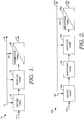
- FIG. 1 illustrates a schematic view of a wastewater treatment process 10. More specifically, the wastewater treatment process provides an energy and cost efficient method for the simultaneous removal of nitrogen, phosphorus, and organic matter from plant influent wastewater. While many systems require an external carbon source and high levels of dissolved oxygen, embodiments of the present invention do not require either, and in fact require very low amounts of dissolved oxygen and carbon in comparison to amounts typically used in wastewater treatment systems. For instance, many systems require an external carbon source for phosphorus removal and nitrogen removal, but in embodiments of the present invention, nitrogen removal requires only minimum amounts of carbon, as it uses mostly ammonia. Further, phosphorus removal uses dissolved and particulate carbon (e.g., particulate organic matter) that is present in the wastewater, instead of only dissolved carbon or an external carbon source.
- dissolved and particulate carbon e.g., particulate organic matter
- plant influent wastewater 12 is raw wastewater that has not yet yet been treated and therefore has not yet entered a wastewater treatment system, such as the wastewater treatment systems that are described herein.
- a first tank shown in FIG. 1 is an anoxic tank 16 that receives at least two streams, including the plant influent wastewater 12 and return activated sludge 14.
- the return activated sludge 14 is a portion of activated sludge that is recycled from the third tank, or the membrane tank 20, into one or more of the other tanks, such as the anoxic tank 16.
- activated sludge is a stream that has been separated from the plant effluent. This activated sludge stream contains a microbial mass, in addition to nitrates and dissolved oxygen.
- the microbial mass includes a variety of biological components, including bacteria, fungi, protozoa, rotifers, etc.
- heterotrophic bacteria While both heterotrophic and autotrophic bacteria may reside in activated sludge, heterotrophic bacteria typically predominate. Heterotrophic bacteria obtain energy from carbonaceous organic matter in plant influent wastewater for the synthesis of new cells. These bacteria then release energy via the conversion of organic matter into compounds, such as carbon dioxide and water. Autotrophic bacteria in activated sludge generally reduce oxidized carbon compounds, such as carbon dioxide, for cell growth. These bacteria obtain their energy by oxidizing ammonia to nitrate, known as nitrification, which is further described herein.
- the return activated sludge 14 is a portion of the activated sludge that is produced by the separation step (e.g., membrane tank or membrane bioreactor) at the end of the treatment process.
- the return activated sludge 14 is recycled into the anoxic tank 16 and provides the tank with microbial mass, residual oxygen, nitrates, and nitrites.
- phosphorus release typically does not occur in anoxic tanks with return activated sludge having nitrates and dissolved oxygen, but in embodiments of the present invention, phosphorus release does occur in the anoxic tank 16. Phosphorus release occurs because the bacteria that is used to consume phosphorus is also present in the return activated sludge 14.
- hydrolysis is the breakdown of polymeric organic matter into monomers by bacterial action.
- hydrolysis refers to a chemical reaction during which molecules of water are split into hydrogen cations and hydroxide anions in the process of a chemical mechanism. This type of reaction is used to break down certain polymers.
- embodiments of the present invention allow for both dissolved and particulate organic matter to be used as a carbon source for phosphorus removal. Normally particulate organic matter cannot be used, but because it is fermented here, it can be used as a carbon source, thus eliminating the need for an external carbon source.
- particulate organic matter occurs as particulate organic matter and dissolved organic matter.
- Three main tests are used for determining the organic matter in wastewater. These include biological oxygen demand (BOD), total organic carbon (TOC), and chemical oxygen demand (COD).
- BOD biological oxygen demand
- TOC total organic carbon
- COD chemical oxygen demand
- particulate organic matter takes the form of suspended solids found in wastewater.
- particulate organic matter undergoes the process of hydrolysis to convert the particulates into soluble solids, thus allowing for higher rates of phosphorus removal when embodiments of the present invention are utilized.
- Phosphorus release and phosphorus uptake refer to the process of phosphorus accumulating organisms (PAOs) storing polyphosphate as an energy reserve in intracellular granules.
- PAOs phosphorus accumulating organisms
- the PAOs release orthophosphate, utilizing the energy to accumulate simple organics and store them as polyhydroxyalkanoates (PHAs).
- PHAs polyhydroxyalkanoates
- the PAOs grow on the stored organic material, using some of the energy to take up orthophosphate and store it as polyphosphate.
- the PAOs when the PAOs store carbon for future growth, the PAOs also release phosphorus, sometimes simultaneously. When the PAOs use stored carbon, they uptake phosphorus.
- an aerated tank has low levels of dissolved oxygen, but the PAOs still uptake phosphorus.
- the PAOs can get energy out of the carbon. Therefore when carbon is abundant, the PAOs store it in their cells and wait until there are conditions where oxygen is present so that they can use the carbon for growth and uptake phosphorus.
- the phosphate is then removed in the waste activated sludge 26, which is generally the activated sludge that is not recycled to the anoxic tank 16.
- the development of the PAO population will be discussed further herein.
- the anoxic tank 16 operates under anoxic conditions such that there is little to no dissolved oxygen, but nitrates (e.g., NO 2 and NO 3 ) may be present. A continuous oxygen deficit is maintained in the anoxic tank.
- the anoxic tank 16 in one embodiment, has a mixer that mixes the plant influent wastewater 12 and the return activated sludge 14 to form a mixed liquor.
- the mixed liquor simply refers to a mixture of plant influent wastewater 12 and return activated sludge 14.
- the rate of mixing may be adjusted, in addition to adjusting the flow rate of the return activated sludge 14, to control the phosphorus release in the anoxic tank 16.
- an external carbon source such as methanol
- denitrification also occurs in the anoxic tank 16.
- Denitrification is the breakdown of nitrites or nitrates to give off nitrogen gas, and occurs as microbes consume oxygen from the nitrites or nitrates. More specifically, denitrification is a microbially facilitated process of dissimilatory nitrate reduction ultimately producing molecular nitrogen (N 2 ), which is returned to the atmosphere. Nitrates and nitrites are converted into nitrogen gas by way of a denitrification process. Denitrification generally reduces oxidized forms of nitrogen in response to the oxidation of an electron donor, such as organic matter which, here, is present in the return activated sludge 14.
- an electron donor such as organic matter which, here, is present in the return activated sludge 14.
- the denitrification process is also conducted by autotrophic nitrifiers under conditions of low dissolved oxygen in the anoxic tank 16 and the aerated tank 18.
- the following reactions illustrate the denitrification process, including an illustrative redox reaction: (1) NO 3 - ⁇ NO 2 - ⁇ NO + N 2 O ⁇ N 2 (g) (2) 2 NO 3 - + 10 e - + 12 H+ ⁇ N 2 + 6 H 2 O
- Particulate organic matter and dissolved organic matter from the plant influent wastewater 12 are fermented in the anoxic tank.
- the conditions in the anoxic tank in embodiments of the present invention induce high rates of hydrolysis and fermentation of particulate organic matter, which provides fermented organic matter in excess of what is needed for the denitrification reaction, allowing for simultaneous release of phosphorus and the formation of PHAs.
- the fermentation of particulate organic matter allows for additional carbon to be used for phosphorus removal.
- the average detention time of the influent wastewater flow in the anoxic tank may vary from one hour to ten hours.
- the dissolved oxygen concentration in the anoxic tank is less than 0.3 mg/L.
- the dissolved oxygen concentration in the anoxic tank is less than 0.2 mg/L.
- the dissolved oxygen concentration in the anoxic tank is 0.1 mg/L or less.
- recirculation rates of the return activated sludge may vary between 0.3 to 6 times the influent flow rate.
- the anoxic mixed liquor is transferred to an aerated tank 18. While a single aerated tank 18 is illustrated in FIG. 1 , multiple aerated tanks may be used, and may be configured either in parallel or in series. Alternatively, one aerated tank may be used, but the aerated tank may have more than one compartment through which the mixed liquor flows. The purpose of having more than one compartment is to improve the kinetic conditions of the overall process minimizing tank volume.
- a portion of the activated sludge is transferred into the aerated tank to provide an additional bacterial population needed to ferment the particulate and dissolved organic matter and to promote phosphorus release. This is advantageous in those cases where the nitrate concentrations in the membrane tank are excessively high.
- the aerated tank 18 provided for in embodiments of the present invention is operated under very low dissolved oxygen concentrations, such as microaerophilic conditions, which promotes the development of the bacterial population (e.g., phosphate accumulating organisms (PAO)) used for phosphorus release and uptake.
- the bacterial population e.g., phosphate accumulating organisms (PAO)
- PAO phosphate accumulating organisms
- this bacterial population is capable of storing phosphorus, such as in the form of polyphosphates, and metabolizes it for energy production and cell synthesis, resulting in the removal of phosphorus from the system through the activated sludge. This particular bacterial population is unable to develop where there are high concentrations of dissolved oxygen.
- nitrification and denitrification also occur in the aerated tank 18.
- nitrification, denitrification, and phosphorus release occur simultaneously in the aerated tank 18.
- denitrification is a microbially facilitated process of dissimilatory nitrate reduction that ultimately produces nitrogen gas by reducing oxidized forms of nitrogen.
- Nitrification is the breakdown of ammonia into nitrate and water. More particularly, nitrification is the biological oxidation of ammonia with oxygen into nitrite followed by the oxidation of nitrites into nitrates.
- AOB ammonia-oxidizing bacteria
- AOA ammonia-oxidizing archaea
- the reactions represented by equations (4) and (6) occur at a minimum, thus reducing the need for oxygen and obtaining significant savings in energy usage.
- very little to no nitrates are found in the mixed liquor because reactions (4) and (6) are such a small percentage of the overall process such that in equation (1) above, it is mainly nitrites rather than nitrates being converted to nitrogen gas.
- equation (2) there are less than 10 electrons needed to convert nitrite to nitrogen gas.
- these electrons rather than coming from methanol or another external carbon source, come from ammonia. This will be discussed in more detail below.
- ammonia is used to convert nitrites into nitrogen gas.
- an external carbon source is not required, some of the ammonia is used for reactions (3) and (5), but some of the ammonia is also used as a reducing source of electrons for denitrification. This is how nitrification and denitrification can occur in systems with low oxygen concentrations and without an external carbon source.
- microaerophilic conditions allow for fermentation of particulate and dissolved organic matter in the aerated tank 18, which would not typically occur with higher concentrations of dissolved oxygen.
- reaction (9) is the net of reactions (7) and (8). Many times, this sequence of reactions requires a high concentration of dissolved oxygen and an external carbon source.
- O 2 per gram of N-NH 3 is required for reaction (7) and about 2.86 grams of COD-O 2 per gram of N-NO 3 are required for reaction (8).
- the equations are as follows: (7) 1 NH 3 + 2 O 2 ⁇ 1 HNO 3 + H 2 O 1 HNO 3 + Organic Matter ⁇ 1 2 N 2 + H 2 O
- Reactions (9) and (10) below illustrate a process called a nitrification shortcut where the initial reaction, or reaction (10), is driven only to nitrite, which results in a savings in the needs of both oxygen demand and organic matter.
- reaction (10) About 3.43 grams of O 2 per gram of N-NH 3 is required for reaction (9) and about 1.71 grams of COD-O 2 per gram of N-NH 3 are required for reaction (10).
- the set of reactions below labeled (11) and (12) occur in the anoxic tank and the aerated tank. In some instances, this set of reactions is referred to as a nitrifier-denitrification process. As shown in equation (11), ammonia and oxygen are converted into nitrogen gas, nitrous acid, and water. Organic matter is then used to convert the nitrous acid into nitrogen gas, water, and carbon dioxide. About 2.28 grams of O 2 per gram of N-NH 3 is required for reaction (11) and about 0.57 grams of COD per gram of N-NH 3 is required for reaction (12). When comparing the three sets of reactions, this third set of reactions (reactions (13)-(15)) requires the least amount of oxygen.
- the mixed liquor is then transferred from the aerated tank 18 to a third tank, here shown as a membrane tank 20, for a solid-liquid separation step where the microorganisms are separated from the treated water.
- a third tank here shown as a membrane tank 20
- the membrane tank 20 separates this sludge from the treated plant effluent 22.
- the membrane tank is a membrane bioreactor that is a combination of a membrane process (e.g., microfiltration, ultrafiltration, hollow fiber, flat sheet, tubular) with a suspended growth bioreactor.
- a bioreactor refers to a device that supports a biologically active environment. Because a bioreactor must be associated with a separation unit to recover the biomass and the purified liquid, and of the inefficiencies and inconvenience of separate units, membrane bioreactors are used to provide the same or better results, but in a single unit. As such, a membrane bioreactor is an association of a biologic reactor and a cross-flow filtration. In one instance, the membrane tank 20 is aerated to provide water turbulence for scouring the submerged membrane filter. In one embodiment, the membrane filter utilized microfiltration, but in another embodiment, ultrafiltration is used.
- the result of the membrane filtration occurring in the membrane tank 20 is at least two exit streams, including treated plant effluent 22 and activated sludge 24, a portion of which is recycled to the anoxic tank 16, and in some embodiments, to the aerated tank 18.
- treated plant effluent 22 is the stream exiting the third tank that has been treated for the removal of carbon, nitrogen, phosphorus, and other unwanted constituents.
- the excess activated sludge is shown as activated sludge 26.
- the amount of activated sludge 24 that is recycled to the anoxic tank 16 varies, but in some embodiments ranges anywhere from 50% to 600% of the amount of plant influent wastewater 12 entering the anoxic tank 16.
- the third tank in the embodiment of FIG. 1 is a clarifier.
- Clarifiers are tanks used to separate, thicken, and recycle the activated sludge. Typically, clarifiers have a much larger footprint than membrane bioreactors.
- FIG. 2 a schematic view is illustrated of an alternate wastewater treatment process.
- An anoxic tank 16a, an aerated tank 18a, and a membrane tank 20a are illustrated in the embodiment of FIG. 2 and operate similarly to those described in FIG. 1 .
- an anaerobic tank 28 is added downstream of, or after the anoxic tank 16a and upstream of, or before the aerated tank 18a.
- the anaerobic tank 28 operates under anaerobic conditions, or under the absence of oxygen.
- the anaerobic tank 28 is a non-aerated tank, such that there is no added oxygen and there are no nitrates.
- the contents are mixed in the anaerobic tank 28 such that a mixer is present.
- FIG. 2 or specifically where an anaerobic tank 28 is added to the system, is used in conditions where the characteristics of the organic matter present in the influent wastewater stream are such that additional retention time is needed for both hydrolysis and fermentation of the particulate organic matter.
- additional phosphorus release takes place in the anaerobic tank 28.
- plant influent wastewater 12a is mixed with return activated sludge 14a in an anoxic tank 16a.
- the mixed liquor is first transferred to an anaerobic tank 28, then to an aerated tank 18a, and finally to a membrane tank 20a. Exiting from the membrane tank 20a is treated plant effluent 22a and activated sludge 24a.
- a portion of the activated sludge 24a is recycled to the anoxic tank 16a as return activated sludge 14a, and optionally, a portion is also recycled to the aerated tank 18a.
- the waste activated sludge 26a in one embodiment, is disposed of.
- FIG. 3 illustrates a line graph 300 showing a decrease of energy usage at a wastewater treatment plant as a result of the implementation of embodiments of the present invention.
- energy usage costs significantly decrease, as the addition of dissolved oxygen costs may account for up to 50% of total energy costs for a wastewater treatment plant.
- the technology described herein was tested and it was found that energy costs significantly decreased at least partially due to the low amounts of dissolved oxygen required in the aerated tank. As shown, before the trial, the highest energy usage is about 64,000 kWh/month, while the highest after the trial is about 54,000 kWh/month, although the levels reached much lower amounts for previous months.
- FIG. 4 a bar graph 400 is illustrated that shows a decrease of both ammonia and phosphate when embodiments of the present invention are implemented in a wastewater treatment plant.
- influent concentrations of ammonia were around 72 mg/l, but dropped to around 1 mg/l after the plant influent wastewater was treated using the treatment methods described herein.
- influent concentrations of phosphate dropped from around 74 mg/l to around 4 mg/l after the plant influent wastewater was treated using the treatment methods described herein.
- Train A represents a typical process that would occur without the user of embodiments of the present invention
- train B represents a process that uses embodiments of the present invention, such as a low dissolved oxygen concentration in the aerated tank, as previously discussed.
- the dissolved oxygen concentration in the aerated tank of train A is 1.3 mg/l
- the dissolved oxygen concentration in the aerated tank of train B is 0.1 mg/l.
- the levels of phosphorus in the membrane tank or the plant effluent are 3.65 mg/l for train B, which is much lower than the levels in the membrane tank for train A, which are 7.41 mg/l.
- simultaneous nitrification-denitrification take place in the aerated tank of train B while only nitrification takes place in the aerated tank of train A, as reflected by the significantly higher difference in nitrate concentration.
- the levels of nitrates/nitrites in the membrane tank for train B are 7.15 mg/l, which is lower than the 8.31 mg/l levels in the membrane tank of train A.
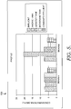
- FIG. 5 illustrates a bar graph 500 showing the concentrations of phosphorus, dissolved oxygen, and nitrates in each tank.
- the levels of phosphorus for example, it can be seen that the levels are much lower in the membrane tank for train B than for train A, which is due, in part, to the low dissolved oxygen concentrations in the aerated tank.
Landscapes
- Life Sciences & Earth Sciences (AREA)
- Biodiversity & Conservation Biology (AREA)
- Microbiology (AREA)
- Water Supply & Treatment (AREA)
- Engineering & Computer Science (AREA)
- Environmental & Geological Engineering (AREA)
- Hydrology & Water Resources (AREA)
- Chemical & Material Sciences (AREA)
- Organic Chemistry (AREA)
- Health & Medical Sciences (AREA)
- Molecular Biology (AREA)
- Purification Treatments By Anaerobic Or Anaerobic And Aerobic Bacteria Or Animals (AREA)
- Separation Using Semi-Permeable Membranes (AREA)
- Treatment Of Water By Oxidation Or Reduction (AREA)
Description
- Removing various components from wastewater, such as nitrogen, carbon, and phosphorus can be a difficult and high-cost process that in some instances may require the addition of a carbon source to wastewater treatment process. Additionally, a high concentration of dissolved oxygen used in many wastewater treatment processes contributes substantially to the cost of energy usage of a wastewater treatment plant. A carbon source, such as methanol, may be added to the process in an anoxic tank, for example, to assist with nitrification and denitrification. Further, an aerated tank may require high concentrations of dissolved oxygen to promote oxidation of biological oxygen demand (BOD) and ammonia. The addition of a carbon source and the requirement of high concentrations of dissolved oxygen, however, are costly and significantly contribute to the expense of treating wastewater.
- A process for treating wastewater to simultaneously remove organic matter, nitrogen, and phosphorus is the subject matter of claim 1 below, and embodiments thereof are the subject matter of the dependent claims below.
- The following documents may be useful in understanding the background to the present disclosure.
-
US 2007/193949 A1 relates to a system and method for treating wastewater containing carbon, nitrogen and phosphorous pollutants using a first reactor containing methanogenic bacteria, and a second reactor containing phosphate accumulating bacteria, and de-nitrifying bacteria, and a third, membrane separation reactor. -
US 6 406 629 B1 describes a waste water treatment process for biologically removing phosphates using a membrane filter. The process includes three zones, an anaerobic zone, an anoxic zone, and an aerobic zone. -
US 2006/113243 A1 describes a wastewater treatment method in which a setpoint value of the oxidation-reduction potential of a mixed liquor is established, and a measured value of the oxidation-reduction potential of a mixed liquor is compared with the setpoint value, and a control signal based at least on part on the comparison step is used to control operation of an aeration device required to add air at various times to maintain a particular process. - Illustrative embodiments of the present invention are described in detail below with reference to the attached drawing figures, and wherein:
-
FIG. 1 illustrates a schematic view of a wastewater treatment process, in accordance with an embodiment of the present invention; -
FIG. 2 illustrates a schematic view of an alternate wastewater treatment process, in accordance with an embodiment of the present invention; -
FIG. 3 illustrates a decrease of energy usage at a wastewater treatment plant as a result of implementation of embodiments of the present invention; -
FIG. 4 illustrates a decrease of both ammonia and phosphate when embodiments of the present invention are implemented in a wastewater treatment plant; and -
FIG. 5 illustrates a bar graph showing the concentrations of phosphorus, dissolved oxygen, and nitrates in each tank. -
FIG. 1 illustrates a schematic view of awastewater treatment process 10. More specifically, the wastewater treatment process provides an energy and cost efficient method for the simultaneous removal of nitrogen, phosphorus, and organic matter from plant influent wastewater. While many systems require an external carbon source and high levels of dissolved oxygen, embodiments of the present invention do not require either, and in fact require very low amounts of dissolved oxygen and carbon in comparison to amounts typically used in wastewater treatment systems. For instance, many systems require an external carbon source for phosphorus removal and nitrogen removal, but in embodiments of the present invention, nitrogen removal requires only minimum amounts of carbon, as it uses mostly ammonia. Further, phosphorus removal uses dissolved and particulate carbon (e.g., particulate organic matter) that is present in the wastewater, instead of only dissolved carbon or an external carbon source. In the embodiment ofFIG. 1 , three separate tanks are used to simultaneously remove nitrogen, phosphorus, and organic matter from plantinfluent wastewater 12.
As used herein, plantinfluent wastewater 12 is raw wastewater that has not yet yet been treated and therefore has not yet entered a wastewater treatment system, such as the wastewater treatment systems that are described herein. - A first tank shown in
FIG. 1 is ananoxic tank 16 that receives at least two streams, including the plantinfluent wastewater 12 and return activatedsludge 14. As will be discussed further herein, the return activatedsludge 14 is a portion of activated sludge that is recycled from the third tank, or themembrane tank 20, into one or more of the other tanks, such as theanoxic tank 16. As used herein, activated sludge is a stream that has been separated from the plant effluent. This activated sludge stream contains a microbial mass, in addition to nitrates and dissolved oxygen. The microbial mass includes a variety of biological components, including bacteria, fungi, protozoa, rotifers, etc. While both heterotrophic and autotrophic bacteria may reside in activated sludge, heterotrophic bacteria typically predominate. Heterotrophic bacteria obtain energy from carbonaceous organic matter in plant influent wastewater for the synthesis of new cells. These bacteria then release energy via the conversion of organic matter into compounds, such as carbon dioxide and water. Autotrophic bacteria in activated sludge generally reduce oxidized carbon compounds, such as carbon dioxide, for cell growth. These bacteria obtain their energy by oxidizing ammonia to nitrate, known as nitrification, which is further described herein. - As mentioned above, the return activated
sludge 14 is a portion of the activated sludge that is produced by the separation step (e.g., membrane tank or membrane bioreactor) at the end of the treatment process. The return activatedsludge 14 is recycled into theanoxic tank 16 and provides the tank with microbial mass, residual oxygen, nitrates, and nitrites. It should be noted that phosphorus release typically does not occur in anoxic tanks with return activated sludge having nitrates and dissolved oxygen, but in embodiments of the present invention, phosphorus release does occur in theanoxic tank 16. Phosphorus release occurs because the bacteria that is used to consume phosphorus is also present in the return activatedsludge 14. Additionally, phosphorus release occurs because of active hydrolysis and fermentation conditions of particulate organic matter present in the influent wastewater. As used herein, hydrolysis is the breakdown of polymeric organic matter into monomers by bacterial action. In one embodiment, hydrolysis refers to a chemical reaction during which molecules of water are split into hydrogen cations and hydroxide anions in the process of a chemical mechanism. This type of reaction is used to break down certain polymers. As such, instead of just using dissolved organic matter as the carbon source for phosphorus removal, embodiments of the present invention allow for both dissolved and particulate organic matter to be used as a carbon source for phosphorus removal. Normally particulate organic matter cannot be used, but because it is fermented here, it can be used as a carbon source, thus eliminating the need for an external carbon source. - In wastewater, organic matter occurs as particulate organic matter and dissolved organic matter. Three main tests are used for determining the organic matter in wastewater. These include biological oxygen demand (BOD), total organic carbon (TOC), and chemical oxygen demand (COD). Unlike dissolved organic matter, particulate organic matter takes the form of suspended solids found in wastewater. As further discussed herein, particulate organic matter undergoes the process of hydrolysis to convert the particulates into soluble solids, thus allowing for higher rates of phosphorus removal when embodiments of the present invention are utilized.
- Phosphorus release and phosphorus uptake refer to the process of phosphorus accumulating organisms (PAOs) storing polyphosphate as an energy reserve in intracellular granules. In anaerobic conditions, the PAOs release orthophosphate, utilizing the energy to accumulate simple organics and store them as polyhydroxyalkanoates (PHAs). In aerobic conditions, or at least conditions where there is some oxygen present, the PAOs grow on the stored organic material, using some of the energy to take up orthophosphate and store it as polyphosphate. As such, when the PAOs store carbon for future growth, the PAOs also release phosphorus, sometimes simultaneously. When the PAOs use stored carbon, they uptake phosphorus. As will be further described herein, an aerated tank has low levels of dissolved oxygen, but the PAOs still uptake phosphorus. When oxygen is present, the PAOs can get energy out of the carbon. Therefore when carbon is abundant, the PAOs store it in their cells and wait until there are conditions where oxygen is present so that they can use the carbon for growth and uptake phosphorus. The phosphate is then removed in the waste activated
sludge 26, which is generally the activated sludge that is not recycled to theanoxic tank 16. The development of the PAO population will be discussed further herein. Theanoxic tank 16 operates under anoxic conditions such that there is little to no dissolved oxygen, but nitrates (e.g., NO2 and NO3) may be present. A continuous oxygen deficit is maintained in the anoxic tank. - The
anoxic tank 16, in one embodiment, has a mixer that mixes the plantinfluent wastewater 12 and the return activatedsludge 14 to form a mixed liquor. The mixed liquor, as used herein, simply refers to a mixture of plantinfluent wastewater 12 and return activatedsludge 14. The rate of mixing may be adjusted, in addition to adjusting the flow rate of the return activatedsludge 14, to control the phosphorus release in theanoxic tank 16. It should be noted that the addition of an external carbon source, such as methanol, is avoided in embodiments of the present invention such that there is no additional carbon source needed to carry out embodiments of the present invention. In addition to phosphorus release, denitrification also occurs in theanoxic tank 16. Denitrification is the breakdown of nitrites or nitrates to give off nitrogen gas, and occurs as microbes consume oxygen from the nitrites or nitrates. More specifically, denitrification is a microbially facilitated process of dissimilatory nitrate reduction ultimately producing molecular nitrogen (N2), which is returned to the atmosphere. Nitrates and nitrites are converted into nitrogen gas by way of a denitrification process. Denitrification generally reduces oxidized forms of nitrogen in response to the oxidation of an electron donor, such as organic matter which, here, is present in the return activatedsludge 14. This process is performed primarily by heterotrophic bacteria in an environment where oxygen is depleted, or where oxygen consumption exceeds the rate of oxygen supply, such as theanoxic tank 16 and theaerated tank 18. Utilizing embodiments of the present invention, the denitrification process is also conducted by autotrophic nitrifiers under conditions of low dissolved oxygen in theanoxic tank 16 and theaerated tank 18. The following reactions illustrate the denitrification process, including an illustrative redox reaction:
(1) NO3 - → NO2 - → NO + N2O → N2 (g)
(2) 2 NO3 - + 10 e- + 12 H+ → N2 + 6 H2O
- Particulate organic matter and dissolved organic matter from the plant
influent wastewater 12 are fermented in the anoxic tank. The conditions in the anoxic tank in embodiments of the present invention induce high rates of hydrolysis and fermentation of particulate organic matter, which provides fermented organic matter in excess of what is needed for the denitrification reaction, allowing for simultaneous release of phosphorus and the formation of PHAs. The fermentation of particulate organic matter allows for additional carbon to be used for phosphorus removal. The average detention time of the influent wastewater flow in the anoxic tank may vary from one hour to ten hours. In one embodiment, the dissolved oxygen concentration in the anoxic tank is less than 0.3 mg/L. In further embodiments, the dissolved oxygen concentration in the anoxic tank is less than 0.2 mg/L. In an even further embodiment, the dissolved oxygen concentration in the anoxic tank is 0.1 mg/L or less. Further, recirculation rates of the return activated sludge may vary between 0.3 to 6 times the influent flow rate. - The anoxic mixed liquor is transferred to an
aerated tank 18. While a singleaerated tank 18 is illustrated inFIG. 1 , multiple aerated tanks may be used, and may be configured either in parallel or in series. Alternatively, one aerated tank may be used, but the aerated tank may have more than one compartment through which the mixed liquor flows. The purpose of having more than one compartment is to improve the kinetic conditions of the overall process minimizing tank volume. Optionally, a portion of the activated sludge is transferred into the aerated tank to provide an additional bacterial population needed to ferment the particulate and dissolved organic matter and to promote phosphorus release. This is advantageous in those cases where the nitrate concentrations in the membrane tank are excessively high. Unlike many aerated tanks, theaerated tank 18 provided for in embodiments of the present invention is operated under very low dissolved oxygen concentrations, such as microaerophilic conditions, which promotes the development of the bacterial population (e.g., phosphate accumulating organisms (PAO)) used for phosphorus release and uptake. Generally, this bacterial population is capable of storing phosphorus, such as in the form of polyphosphates, and metabolizes it for energy production and cell synthesis, resulting in the removal of phosphorus from the system through the activated sludge. This particular bacterial population is unable to develop where there are high concentrations of dissolved oxygen. Since this particular bacterial population is able to develop in theaerated tank 18, it is also present in the return activatedsludge 14 that is recycled to theanoxic tank 16, thereby allowing for phosphorus release in theanoxic tank 16. Phosphorus uptake may occur simultaneously with phosphorus release in theaerated tank 18. - In addition to phosphorus release and phosphorus uptake, nitrification and denitrification also occur in the
aerated tank 18. In one embodiment, nitrification, denitrification, and phosphorus release occur simultaneously in theaerated tank 18. As previously described, denitrification is a microbially facilitated process of dissimilatory nitrate reduction that ultimately produces nitrogen gas by reducing oxidized forms of nitrogen. Nitrification, on the other hand, is the breakdown of ammonia into nitrate and water. More particularly, nitrification is the biological oxidation of ammonia with oxygen into nitrite followed by the oxidation of nitrites into nitrates. Two groups of organisms are generally responsible for the oxidation of ammonia into nitrite. These two groups are ammonia-oxidizing bacteria (AOB) and ammonia-oxidizing archaea (AOA). The following equations represent the nitrification process:
(3) NH3 + CO2 + 1.5 O2 + Nitrosomonas → NO2 - + H2O + H+
(4) NO2 - + CO2 + 0.5 O2 + Nitrobacter → NO3 -
(5) NH3 + O2 → NO2 - + 3H+ + 2e-
(6) NO2 - + H2O → NO3 - + 2H+ + 2e-
- In embodiments of the present invention, however, the reactions represented by equations (4) and (6) occur at a minimum, thus reducing the need for oxygen and obtaining significant savings in energy usage. In some embodiments, very little to no nitrates are found in the mixed liquor because reactions (4) and (6) are such a small percentage of the overall process such that in equation (1) above, it is mainly nitrites rather than nitrates being converted to nitrogen gas. As such, in equation (2), there are less than 10 electrons needed to convert nitrite to nitrogen gas. In embodiments of the present invention, these electrons, rather than coming from methanol or another external carbon source, come from ammonia. This will be discussed in more detail below. As shown by reactions (3) and (5) above, ammonia is used to convert nitrites into nitrogen gas. As an external carbon source is not required, some of the ammonia is used for reactions (3) and (5), but some of the ammonia is also used as a reducing source of electrons for denitrification. This is how nitrification and denitrification can occur in systems with low oxygen concentrations and without an external carbon source.
- Further, the microaerophilic conditions allow for fermentation of particulate and dissolved organic matter in the
aerated tank 18, which would not typically occur with higher concentrations of dissolved oxygen. - As mentioned above, nitrification and denitrification occur in both the anoxic and aerated tanks, according to embodiments of the present invention. Conventional nitrification-denitrification is represented by reactions (7), (8), and (9) below. Reaction (9) is the net of reactions (7) and (8). Many times, this sequence of reactions requires a high concentration of dissolved oxygen and an external carbon source. Here, about 4.57 grams of O2 per gram of N-NH3 are required for reaction (7) and about 2.86 grams of COD-O2 per gram of N-NO3 are required for reaction (8). The equations are as follows:
(7) 1NH 3 + 2O 2 → 1HNO 3 + H 2 O

- Reactions (9) and (10) below illustrate a process called a nitrification shortcut where the initial reaction, or reaction (10), is driven only to nitrite, which results in a savings in the needs of both oxygen demand and organic matter. About 3.43 grams of O2 per gram of N-NH3 is required for reaction (9) and about 1.71 grams of COD-O2 per gram of N-NH3 are required for reaction (10). In one instance, when comparing the first set of reactions above (reactions (7)-(8)) to the second set of reactions below (reactions (9)-(10)), the oxygen demand is decreased by about 25% (4.57 g O2 / g N-NH3 -3.43 g O2 / g N-NH3 = 1.15 g O2 / g N-NH3) and the need for organic matter is decreased by about 40% (2.86 g O2 / g N-NO3 - 1.71 g O2 / g N-NH3 = 1.15 g COD / g N-NH3).


- The set of reactions below labeled (11) and (12) occur in the anoxic tank and the aerated tank.. In some instances, this set of reactions is referred to as a nitrifier-denitrification process. As shown in equation (11), ammonia and oxygen are converted into nitrogen gas, nitrous acid, and water. Organic matter is then used to convert the nitrous acid into nitrogen gas, water, and carbon dioxide. About 2.28 grams of O2 per gram of N-NH3 is required for reaction (11) and about 0.57 grams of COD per gram of N-NH3 is required for reaction (12). When comparing the three sets of reactions, this third set of reactions (reactions (13)-(15)) requires the least amount of oxygen. The savings in organic matter is about 80% (2.86 g O2 / g N-NO3 - 0.57 g COD / g N-NH3 = 2.29 g O2 / g N) when comparing the amount of organic matter required for the third set of reactions below to the first set of reactions (reactions (7)-(8)). Further, the savings in oxygen required between the first and the third set of equations is about 50% (4.57 g O2 / g N-NH3 - 2.28 g O2 / g N-NH3 = 2.28 g O2 / g N).


- Returning to
FIG. 1 , the mixed liquor is then transferred from the aeratedtank 18 to a third tank, here shown as amembrane tank 20, for a solid-liquid separation step where the microorganisms are separated from the treated water. In activated sludge processes, such as those described herein, the dissolved organic pollutants are transformed into water, carbon dioxide, and biomass, which results in an excess production of sludge. Themembrane tank 20 separates this sludge from the treatedplant effluent 22. In one embodiment, the membrane tank is a membrane bioreactor that is a combination of a membrane process (e.g., microfiltration, ultrafiltration, hollow fiber, flat sheet, tubular) with a suspended growth bioreactor. A bioreactor refers to a device that supports a biologically active environment. Because a bioreactor must be associated with a separation unit to recover the biomass and the purified liquid, and of the inefficiencies and inconvenience of separate units, membrane bioreactors are used to provide the same or better results, but in a single unit. As such, a membrane bioreactor is an association of a biologic reactor and a cross-flow filtration. In one instance, themembrane tank 20 is aerated to provide water turbulence for scouring the submerged membrane filter. In one embodiment, the membrane filter utilized microfiltration, but in another embodiment, ultrafiltration is used. - The result of the membrane filtration occurring in the
membrane tank 20 is at least two exit streams, including treatedplant effluent 22 and activatedsludge 24, a portion of which is recycled to theanoxic tank 16, and in some embodiments, to theaerated tank 18. As used herein, treatedplant effluent 22 is the stream exiting the third tank that has been treated for the removal of carbon, nitrogen, phosphorus, and other unwanted constituents. The excess activated sludge is shown as activatedsludge 26. The amount of activatedsludge 24 that is recycled to theanoxic tank 16 varies, but in some embodiments ranges anywhere from 50% to 600% of the amount of plantinfluent wastewater 12 entering theanoxic tank 16. As such, for every 3.7 litres (one gallon) of plantinfluent wastewater 12, about 1.9 to about 22.7 litres (0.5 to 6 gallons) of return activatedsludge 14 may be added to theanoxic tank 16. In an alternative embodiment, the third tank in the embodiment ofFIG. 1 , although illustrated as amembrane tank 20, is a clarifier. Clarifiers are tanks used to separate, thicken, and recycle the activated sludge. Typically, clarifiers have a much larger footprint than membrane bioreactors. - Referring now to
FIG. 2 , a schematic view is illustrated of an alternate wastewater treatment process. Ananoxic tank 16a, anaerated tank 18a, and amembrane tank 20a are illustrated in the embodiment ofFIG. 2 and operate similarly to those described inFIG. 1 . Here, ananaerobic tank 28 is added downstream of, or after theanoxic tank 16a and upstream of, or before theaerated tank 18a. Generally, theanaerobic tank 28 operates under anaerobic conditions, or under the absence of oxygen. Theanaerobic tank 28 is a non-aerated tank, such that there is no added oxygen and there are no nitrates. The contents are mixed in theanaerobic tank 28 such that a mixer is present. The embodiment ofFIG. 2 , or specifically where ananaerobic tank 28 is added to the system, is used in conditions where the characteristics of the organic matter present in the influent wastewater stream are such that additional retention time is needed for both hydrolysis and fermentation of the particulate organic matter. In one embodiment, additional phosphorus release takes place in theanaerobic tank 28. Similar to that described inFIG. 1 , plantinfluent wastewater 12a is mixed with return activatedsludge 14a in ananoxic tank 16a. The mixed liquor is first transferred to ananaerobic tank 28, then to anaerated tank 18a, and finally to amembrane tank 20a. Exiting from themembrane tank 20a is treatedplant effluent 22a and activatedsludge 24a. A portion of the activatedsludge 24a is recycled to theanoxic tank 16a as return activatedsludge 14a, and optionally, a portion is also recycled to theaerated tank 18a. The waste activatedsludge 26a, in one embodiment, is disposed of. -
FIG. 3 illustrates aline graph 300 showing a decrease of energy usage at a wastewater treatment plant as a result of the implementation of embodiments of the present invention. As mentioned, when dissolved oxygen concentrations are kept to a minimum in the aerated tank, energy usage costs significantly decrease, as the addition of dissolved oxygen costs may account for up to 50% of total energy costs for a wastewater treatment plant. As indicated by "trial started," the technology described herein was tested and it was found that energy costs significantly decreased at least partially due to the low amounts of dissolved oxygen required in the aerated tank. As shown, before the trial, the highest energy usage is about 64,000 kWh/month, while the highest after the trial is about 54,000 kWh/month, although the levels reached much lower amounts for previous months. - Turning now to
FIG. 4 , abar graph 400 is illustrated that shows a decrease of both ammonia and phosphate when embodiments of the present invention are implemented in a wastewater treatment plant. As shown here, influent concentrations of ammonia were around 72 mg/l, but dropped to around 1 mg/l after the plant influent wastewater was treated using the treatment methods described herein. Further, influent concentrations of phosphate dropped from around 74 mg/l to around 4 mg/l after the plant influent wastewater was treated using the treatment methods described herein. - The following example illustrates a plant that has two parallel trains, including a first train (train A) and a second train (train B). The tanks in each trains are identical and are in the same location. The conditions in the tanks, however, are different. Train A represents a typical process that would occur without the user of embodiments of the present invention, while train B represents a process that uses embodiments of the present invention, such as a low dissolved oxygen concentration in the aerated tank, as previously discussed. For example, as shown below in Table 1, the dissolved oxygen concentration in the aerated tank of train A is 1.3 mg/l, while the dissolved oxygen concentration in the aerated tank of train B is 0.1 mg/l. As shown by the levels of phosphorus and nitrate/nitrite removal, in train B compared with those of train A, the lower levels of dissolved oxygen in the aerated tank allow for the development of the phosphorus-removal bacteria in the aerated tank. These phosphorus-removal bacteria are then present in the return activated sludge (not shown) from the membrane tank back to the anoxic tank. Phosphorus release is observed in the anoxic tank of train B, while not in the anoxic tank of train A. Net phosphorus uptake takes place in the aerated tank of train B and not in the aerated tank of train A. Therefore, higher levels of phosphorus uptake and removal in the process occur. As a result, the levels of phosphorus in the membrane tank or the plant effluent are 3.65 mg/l for train B, which is much lower than the levels in the membrane tank for train A, which are 7.41 mg/l. Similarly, simultaneous nitrification-denitrification take place in the aerated tank of train B while only nitrification takes place in the aerated tank of train A, as reflected by the significantly higher difference in nitrate concentration. The levels of nitrates/nitrites in the membrane tank for train B are 7.15 mg/l, which is lower than the 8.31 mg/l levels in the membrane tank of train A.
- Continuing with the example described above and illustrated in Table 1 below,
FIG. 5 illustrates abar graph 500 showing the concentrations of phosphorus, dissolved oxygen, and nitrates in each tank. In comparing the levels of phosphorus, for example, it can be seen that the levels are much lower in the membrane tank for train B than for train A, which is due, in part, to the low dissolved oxygen concentrations in the aerated tank.
- Many different arrangements of the various components depicted, as well as components not shown, are possible without departing from the scope of the claims below. Embodiments of the technology have been described with the intent to be illustrative rather than restrictive. Alternative embodiments will become apparent to readers of this disclosure. Further, alternative means of implementing the aforementioned can be completed without departing from the scope of the claims below. Certain features and subcombinations are of utility and may be employed without reference to other features and subcombinations and are contemplated within the scope of the claims.
Claims (4)
- A process for treating wastewater to simultaneously remove organic matter, nitrogen, and phosphorus, the process comprising:- providing two or more streams in a first tank (16) operating under anoxic conditions, the two or more streams including plant influent wastewater (12) that is raw water that has not yet been treated, and return activated sludge (14);- mixing the plant influent wastewater (12) and the return activated sludge (14) in the first tank (16) to form a mixed liquor, thereby initiating phosphorus release and fermentation of particulate organic matter and dissolved organic matter and controlling the phosphorus release in the first tank (16) by adjusting the rate of mixing of the plant influent wastewater (12) and return activated sludge (14) in addition to adjusting the flow rate of the return activated sludge (14);- transferring the mixed liquor to a second tank (18) operating under microaerophilic conditions, wherein a concentration of dissolved oxygen in the second tank (18) is less than 1.0 mg/l, which is effective to promote simultaneous nitrification, denitrification, phosphorous release, and phosphorus uptake; and- transferring the mixed liquor to a third tank (20) that separates treated effluent from activated sludge containing microorganisms, wherein a first portion of the activated sludge is returned to the first tank (16) as the return activated sludge (14).
- The process of claim 1, wherein the third tank (20) is a membrane bioreactor or a clarifier.
- The process of claim 1, further comprising adding a second portion of the activated sludge (14) into the second tank (18).
- The process of claim 1, wherein the return activated sludge (14) provided in the first tank (16) comprises residual oxygen, nitrates, and nitrites.
Applications Claiming Priority (2)
| Application Number | Priority Date | Filing Date | Title |
|---|---|---|---|
| US12/886,321 US8747671B2 (en) | 2010-09-20 | 2010-09-20 | Simultaneous anoxic biological phosphorus and nitrogen removal |
| PCT/US2011/050655 WO2012039931A1 (en) | 2010-09-20 | 2011-09-07 | Simultaneous anoxic biological phosphorus and nitrogen removal |
Publications (3)
| Publication Number | Publication Date |
|---|---|
| EP2496531A1 EP2496531A1 (en) | 2012-09-12 |
| EP2496531A4 EP2496531A4 (en) | 2013-07-24 |
| EP2496531B1 true EP2496531B1 (en) | 2017-03-15 |
Family
ID=44513535
Family Applications (2)
| Application Number | Title | Priority Date | Filing Date |
|---|---|---|---|
| EP11827130.3A Not-in-force EP2496530B1 (en) | 2010-09-20 | 2011-07-07 | Method for reducing nutrients from wastewater |
| EP11827190.7A Not-in-force EP2496531B1 (en) | 2010-09-20 | 2011-09-07 | Simultaneous anoxic biological phosphorus and nitrogen removal |
Family Applications Before (1)
| Application Number | Title | Priority Date | Filing Date |
|---|---|---|---|
| EP11827130.3A Not-in-force EP2496530B1 (en) | 2010-09-20 | 2011-07-07 | Method for reducing nutrients from wastewater |
Country Status (17)
| Country | Link |
|---|---|
| US (3) | US8747671B2 (en) |
| EP (2) | EP2496530B1 (en) |
| JP (2) | JP5961169B2 (en) |
| KR (2) | KR20130111920A (en) |
| CN (2) | CN102753488B (en) |
| BR (2) | BR112012022818A2 (en) |
| CA (2) | CA2784929C (en) |
| CL (1) | CL2012001408A1 (en) |
| CO (2) | CO6541587A2 (en) |
| EG (1) | EG27126A (en) |
| IL (1) | IL220033A0 (en) |
| IN (1) | IN2012DN04945A (en) |
| MX (2) | MX345406B (en) |
| PE (2) | PE20131020A1 (en) |
| SG (2) | SG181062A1 (en) |
| WO (2) | WO2012039814A1 (en) |
| ZA (2) | ZA201203980B (en) |
Families Citing this family (57)
| Publication number | Priority date | Publication date | Assignee | Title |
|---|---|---|---|---|
| CA2752747C (en) | 2009-02-18 | 2019-05-07 | Anaergia Inc. | Anaerobic fermentation to produce biogas |
| PL391606A1 (en) * | 2010-06-24 | 2012-01-02 | Jerzy Robert Ślusarczyk | Method for biological wastewater treatment |
| AU2011288881A1 (en) * | 2010-08-13 | 2013-02-28 | Anaergia Inc. | Treatment of municipal wastewater with anaerobic digestion |
| US8747671B2 (en) | 2010-09-20 | 2014-06-10 | American Water Works Company, Inc. | Simultaneous anoxic biological phosphorus and nitrogen removal |
| US8685246B2 (en) | 2010-09-20 | 2014-04-01 | American Water Works Company, Inc. | Simultaneous anoxic biological phosphorus and nitrogen removal with energy recovery |
| WO2012103629A1 (en) | 2011-02-03 | 2012-08-09 | Anaergia Inc. | Treatment of waste products with anaerobic digestion |
| US20130092612A1 (en) * | 2011-10-14 | 2013-04-18 | Kevin S. Crane | Sludge thickening and ammonia treatment system |
| WO2013140925A1 (en) * | 2012-03-23 | 2013-09-26 | 水ing株式会社 | Treatment method and treatment device for oil-containing waste water |
| US10167216B2 (en) | 2012-09-14 | 2019-01-01 | Gregory D. Graves | High efficiency wastewater treatment system |
| US10676383B2 (en) | 2012-09-14 | 2020-06-09 | Gregory D. Graves | High efficiency wastewater treatment system |
| US9719704B2 (en) | 2013-02-19 | 2017-08-01 | Natural Systems Utilities, Llc | Systems and methods for recovering energy from wastewater |
| AU2013378840B2 (en) * | 2013-02-22 | 2017-10-26 | General Electric Company | Wastewater treatment with membrane aerated biofilm and anaerobic digester |
| KR102676543B1 (en) | 2013-02-22 | 2024-06-18 | 비엘 테크놀러지스 인크. | Membrane assembly for supporting a biofilm |
| CA3207201A1 (en) | 2014-03-20 | 2015-09-24 | Bl Technologies, Inc. | Wastewater treatment with primary treatment and mbr or mabr-ifas reactor |
| CN104609648B (en) * | 2014-12-24 | 2017-01-18 | 上海电气集团股份有限公司 | Sewage treatment device for chemical industry park and sewage treatment method thereof |
| US9809481B2 (en) | 2015-01-27 | 2017-11-07 | Anaergia Inc. | Treatment of waste products with anaerobic digestion |
| CN104671410B (en) * | 2015-01-30 | 2016-06-29 | 华东理工大学 | Method to the further denitrogenation of high ammonia-nitrogen wastewater on A/O Process ba-sis |
| US10332014B2 (en) | 2015-08-26 | 2019-06-25 | International Business Machines Corporation | Concise state model for operational optimization of wastewater treatment unit(s) |
| CN105174643B (en) * | 2015-10-11 | 2017-11-03 | 北京工业大学 | A kind of nitrosation denitrification nitrogen and phosphorus removal device and method of the low C/P sewage of continuous stream |
| US10584046B2 (en) * | 2015-10-28 | 2020-03-10 | Kaneka Corporation | Nitrogen removal method, nitrification-reaction promoting agent for water treatment, and water treatment method |
| CN105254140B (en) * | 2015-11-23 | 2017-07-04 | 中冶赛迪上海工程技术有限公司 | A kind of MBBR and the compound coking chemical waste water two-stage A/O enhanced biological nitrogen removal techniques of activated sludge process |
| CN105712481A (en) * | 2016-02-26 | 2016-06-29 | 重庆工商大学 | Ecological restoration method for lakes and rivers |
| CN105906044B (en) * | 2016-06-17 | 2018-12-18 | 北京工业大学 | The device and method of the synchronous endogenous denitrification processing Low-carbon Urban Wastewater of Anammox coupling denitrification dephosphorization |
| US10703658B2 (en) | 2017-03-06 | 2020-07-07 | Tangent Company Llc | Home sewage treatment system |
| CN107129044B (en) * | 2017-06-02 | 2020-12-15 | 深圳市太空科技南方研究院 | Efficient reuse and treatment method of manned spacecraft urine |
| CN108373240B (en) * | 2018-04-11 | 2021-07-27 | 东华大学 | A kind of cotton printing and dyeing wastewater treatment and reuse integrated process |
| JP2019214002A (en) * | 2018-06-11 | 2019-12-19 | Jfeエンジニアリング株式会社 | Waste water treatment system |
| CN108911139A (en) * | 2018-08-15 | 2018-11-30 | 陕西朗正环保科技有限公司 | A kind of induction generates the sewage disposal system and method for short-cut nitrification and denitrification |
| CN110885160B (en) * | 2018-09-07 | 2022-04-19 | 斗山重工业建设有限公司 | Water treatment apparatus and method for removing nitrogen contained in water to be treated |
| CA3135606A1 (en) | 2019-04-01 | 2020-10-08 | Carollo Engineers, Inc. | Flow through aerobic granular sludge system and method |
| EE05835B1 (en) * | 2019-06-18 | 2021-05-17 | Tallinna Tehnikaülikool | Method for the removal of nitrogen and phosphorus from wastewater using segregated activated sludge communities in a two-stage bioreactor with differentiated aeration |
| KR102099380B1 (en) * | 2019-07-03 | 2020-04-13 | 주식회사 부강테크 | The Method to Remove Nitrogen and Phosphorus from Wastewater by Changing of Reactor and Recycle Method of Conventional Nutrient Removal Process and by Combining Anaerobic Ammonium Oxidation(ANAMMOX) Process |
| US11637365B2 (en) | 2019-08-21 | 2023-04-25 | Ticona Llc | Polymer composition for use in an antenna system |
| US11258184B2 (en) | 2019-08-21 | 2022-02-22 | Ticona Llc | Antenna system including a polymer composition having a low dissipation factor |
| US12441879B2 (en) | 2019-08-21 | 2025-10-14 | Ticona Llc | Polymer composition for laser direct structuring |
| US12209164B2 (en) | 2019-09-10 | 2025-01-28 | Ticona Llc | Polymer composition and film for use in 5G applications |
| US12294185B2 (en) | 2019-09-10 | 2025-05-06 | Ticona Llc | Electrical connector formed from a polymer composition having a low dielectric constant and dissipation factor |
| US11912817B2 (en) | 2019-09-10 | 2024-02-27 | Ticona Llc | Polymer composition for laser direct structuring |
| US12142820B2 (en) | 2019-09-10 | 2024-11-12 | Ticona Llc | 5G system containing a polymer composition |
| US11555113B2 (en) | 2019-09-10 | 2023-01-17 | Ticona Llc | Liquid crystalline polymer composition |
| US11917753B2 (en) | 2019-09-23 | 2024-02-27 | Ticona Llc | Circuit board for use at 5G frequencies |
| US11646760B2 (en) | 2019-09-23 | 2023-05-09 | Ticona Llc | RF filter for use at 5G frequencies |
| US11721888B2 (en) | 2019-11-11 | 2023-08-08 | Ticona Llc | Antenna cover including a polymer composition having a low dielectric constant and dissipation factor |
| EE05854B1 (en) * | 2019-12-19 | 2023-05-15 | Tallinna Tehnikaülikool | A method for removing nitrogen and phosphorus from wastewater using segregated activated sludge communities in a multi-stage biorefinery |
| CN115700014A (en) | 2020-02-26 | 2023-02-03 | 提克纳有限责任公司 | Circuit structure |
| CN111606419B (en) * | 2020-06-01 | 2022-05-06 | 北京工业大学 | An energy self-sufficient sewage treatment system and method |
| CN111559834A (en) * | 2020-06-10 | 2020-08-21 | 华电水务科技股份有限公司 | Synchronous denitrification coupling enhanced nitrification sewage treatment system and method |
| CN111995055A (en) * | 2020-09-17 | 2020-11-27 | 天津大学 | Two segmentation SBR reaction equipment of denitrifying phosphorus removal fungus enrichment fast |
| EP4222116A4 (en) * | 2020-09-29 | 2024-06-05 | Carollo Engineers, Inc. | SYSTEM AND METHOD FOR WASTEWATER TREATMENT USING AEROBIC GRANULAR SLURRY WITH SUBMERGED MEMBRANE SEPARATION |
| US11728559B2 (en) | 2021-02-18 | 2023-08-15 | Ticona Llc | Polymer composition for use in an antenna system |
| CN113415899B (en) * | 2021-06-25 | 2023-06-09 | 北京工业大学 | Apparatus and method for deep denitrification based on adsorption hydrolysis coupled with short-range denitrification in series with anaerobic ammonium oxidation based on slow-degrading organic matter |
| CN113461161A (en) * | 2021-07-04 | 2021-10-01 | 北京工业大学 | Device for removing nitrogen and granular organic matters by utilizing hydrolysis acidification short-cut denitrification anaerobic ammonia oxidation integrated process |
| CN114054482A (en) * | 2021-11-15 | 2022-02-18 | 西安建筑科技大学 | Device and method for preparing high-concentration dissolved carbon source from kitchen waste |
| KR102774673B1 (en) | 2022-09-13 | 2025-03-04 | 김대일 | Device for preventing spilling out of ice-cream cone and ice-cream cone with the same |
| GB2635744A (en) * | 2023-11-24 | 2025-05-28 | Nexom Inc | Improved simultaneous nitritation and denitritation system |
| KR102856320B1 (en) | 2025-01-02 | 2025-09-04 | 김용성 | Twin toothbrush |
| CN120864664B (en) * | 2025-09-23 | 2025-12-30 | 山东师范大学 | Wetland plant biochar-derived dissolved organic matter coupled with δ-manganese dioxide water treatment agent |
Family Cites Families (55)
| Publication number | Priority date | Publication date | Assignee | Title |
|---|---|---|---|---|
| JPS58146495A (en) * | 1982-02-26 | 1983-09-01 | Ebara Infilco Co Ltd | Treatment of organic waste liquid |
| JPS61249597A (en) | 1985-04-26 | 1986-11-06 | Hitachi Ltd | Method for controlling methanol injection in biological denitrification process |
| US4867883A (en) | 1987-04-21 | 1989-09-19 | Hampton Roads Sanitation District Of The Commonwealth Of Virginia | High-rate biological waste water treatment process using activated sludge recycle |
| US5514278A (en) * | 1993-04-12 | 1996-05-07 | Khudenko; Boris M. | Counterflow microbiological processes |
| DE4424298A1 (en) * | 1994-07-09 | 1996-01-11 | Schreiber Berthold | Activated sludge treatment of waste water in single tank |
| DE19501260C1 (en) | 1995-01-18 | 1996-06-05 | Noell Gmbh | Waste water treatment |
| US5540840A (en) | 1995-06-02 | 1996-07-30 | Monsanto Company | Use of fluidized bed reactors for treatment of wastes containing organic nitrogen compounds |
| US5650069A (en) | 1995-09-08 | 1997-07-22 | Kruger, Inc. | Dual-stage biological process for removing nitrogen from wastewater |
| US5989428A (en) * | 1996-06-21 | 1999-11-23 | Goronszy; Mervyn Charles | Controlling wastewater treatment by monitoring oxygen utilization rates |
| US5863433A (en) | 1996-12-02 | 1999-01-26 | Tennessee Valley Authority United States Corp. | Reciprocating subsurface-flow constructed wetlands for improving wastewater treatment |
| US5833856A (en) | 1997-07-18 | 1998-11-10 | Tianjin Municipal Engineering Design And Research Institute | Process for biologically removing phosphorus and nitrogen from wastewater by controlling carbohydrate content therein |
| US6881339B1 (en) | 1997-10-30 | 2005-04-19 | Sud-Chemie Ag | Process for treating industrial and municipal waste water highly loaded with ammonium |
| AU5071199A (en) | 1998-07-24 | 2000-02-14 | Dhv Water Bv | Process for the treatment of waste water containing specific components, e.g. ammonia |
| JP2000107787A (en) * | 1998-10-07 | 2000-04-18 | Mitsubishi Heavy Ind Ltd | Method for treating wastewater |
| US6857162B1 (en) | 1998-10-12 | 2005-02-22 | Nilfisk Advance A/S | Cleaning and/or treatment device |
| US6485645B1 (en) | 1999-07-20 | 2002-11-26 | Zenon Environmental Inc | Biological process for removing phosphorus involving a membrane filter |
| WO2001005715A1 (en) | 1999-07-20 | 2001-01-25 | Zenon Environmental Inc. | Biological process for removing phosphorus involving a membrane filter |
| US7160712B2 (en) * | 1999-09-21 | 2007-01-09 | Novozymes A/S | Odor control |
| GB0004921D0 (en) | 2000-03-02 | 2000-04-19 | Waterleau Global Water Technol | System for sustainable treatment of municipal and industrial wastewater |
| JP4742403B2 (en) * | 2000-05-10 | 2011-08-10 | 栗田工業株式会社 | Wastewater treatment method |
| US7261811B2 (en) | 2000-10-02 | 2007-08-28 | The University Of Western Ontario | Liquid-solid circulating fluidized bed waste water treatment system for simultaneous carbon, nitrogen and phosphorus removal |
| US7736513B2 (en) | 2000-10-02 | 2010-06-15 | The University Of Western Ontario | Liquid-solid fluidized bed waste water treatment system for simultaneous carbon, nitrogen and phosphorous removal |
| US6555002B2 (en) | 2000-10-06 | 2003-04-29 | Premier Wastwater International, Llc | Apparatus and method for wastewater treatment with enhanced solids reduction (ESR) |
| US7585413B2 (en) | 2001-02-20 | 2009-09-08 | Hoffland Robert O | Method and apparatus for treating animal waste and wastewater |
| US7429328B2 (en) * | 2001-03-02 | 2008-09-30 | Advanced Treatment Sciences, Inc. | Apparatus and methods for control of waste treatment processes |
| US20020004087A1 (en) | 2001-06-04 | 2002-01-10 | Brad Baker | Soda bottle confectionery |
| KR100441208B1 (en) * | 2001-10-24 | 2004-07-22 | 삼성엔지니어링 주식회사 | Batch style waste water treatment apparatus using biological filtering process and waste water treatment method using the same |
| US6712970B1 (en) | 2002-01-11 | 2004-03-30 | Enviroquip, Inc. | Sewage treatment process with phosphorus removal |
| KR100419431B1 (en) | 2002-02-28 | 2004-02-18 | 삼성엔지니어링 주식회사 | Wastewater treatment apparatus and method for removing nitrogen and phosphorus |
| US6706185B2 (en) | 2002-05-22 | 2004-03-16 | Kurita Water Industries Ltd. | Biological method of phosphorus removal and biological phosphorus-removing apparatus |
| DE10223192A1 (en) | 2002-05-24 | 2003-12-11 | Disetronic Licensing Ag | Ampoule and delivery device |
| WO2004002904A1 (en) | 2002-06-28 | 2004-01-08 | Kingsford Environmental (H.K.) Ltd. | Combined activated sludge-biofilm sequencing batch reactor and process |
| US7300571B2 (en) | 2003-02-13 | 2007-11-27 | Zenon Technology Partnership | Supported biofilm apparatus |
| US6946073B2 (en) | 2003-09-02 | 2005-09-20 | Ch2M Hill, Inc. | Method for treating wastewater in a membrane bioreactor to produce a low phosphorus effluent |
| US7413654B2 (en) | 2003-12-23 | 2008-08-19 | Siemens Water Technologies Holding Corp. | Wastewater treatment control |
| JP4570069B2 (en) * | 2004-01-30 | 2010-10-27 | 新日本製鐵株式会社 | Method for removing ammonia nitrogen from wastewater |
| US7252765B2 (en) | 2004-03-01 | 2007-08-07 | Black & Veatch Holding Co. | Process for improving phosphorous removal in waste water treatment without chemical addition |
| JP4373871B2 (en) * | 2004-07-28 | 2009-11-25 | 株式会社神鋼環境ソリューション | Activated sludge treatment equipment |
| US7172699B1 (en) | 2004-10-13 | 2007-02-06 | Eimco Water Technologies Llc | Energy efficient wastewater treatment for nitrogen and phosphorus removal |
| US7279100B2 (en) | 2005-01-31 | 2007-10-09 | Ashbrook Simon-Hartley Operations, Lp | Methods and apparatus for treating wastewater employing a high rate clarifier and a membrane |
| US7326343B2 (en) | 2005-05-03 | 2008-02-05 | University Of Western Ontario Canada | Treatment of wastewater containing phosphorous and nitrogen |
| US7344643B2 (en) | 2005-06-30 | 2008-03-18 | Siemens Water Technologies Holding Corp. | Process to enhance phosphorus removal for activated sludge wastewater treatment systems |
| FR2889180B1 (en) | 2005-08-01 | 2008-04-04 | Suez Environnement Sa | PROCESS AND PLANT FOR TREATING NITROGEN CONCENTRATE EFFLUENTS IN A FRACTIONAL CYCLE SEQUENTIAL BIOLOGICAL REACTOR |
| US7314563B2 (en) | 2005-11-14 | 2008-01-01 | Korea Institute Of Science And Technology | Membrane coupled activated sludge method and apparatus operating anoxic/anaerobic process alternately for removal of nitrogen and phosphorous |
| US7455765B2 (en) | 2006-01-25 | 2008-11-25 | Siemens Water Technologies Corp. | Wastewater treatment system and method |
| TWI316923B (en) | 2006-02-17 | 2009-11-11 | Ind Tech Res Inst | System and method for treating carbon, nitrogen, phosphorous containing wastewater |
| US7713413B2 (en) | 2006-04-11 | 2010-05-11 | Siemens Water Technologies Corp. | Aerated anoxic membrane bioreactor |
| US7850848B2 (en) | 2006-09-18 | 2010-12-14 | Limcaco Christopher A | Apparatus and process for biological wastewater treatment |
| US7674379B2 (en) | 2007-06-19 | 2010-03-09 | The United States Of America As Represented By The Secretary Of Agriculture | Wastewater treatment system with simultaneous separation of phosphorus and manure solids |
| CN101407359A (en) * | 2007-10-12 | 2009-04-15 | 金明记 | Method and apparatus for processing municipal sewage by denitrifying phosphorus removal |
| GB0722486D0 (en) | 2007-11-16 | 2007-12-27 | Javel Ltd | Treatment of wastewater |
| US8287734B2 (en) * | 2009-02-27 | 2012-10-16 | Bion Technologies, Inc. | Method for treating nitrogen in waste streams |
| CN101519265B (en) | 2009-04-09 | 2011-07-13 | 孙友峰 | Sewage treatment process and system |
| US8747671B2 (en) | 2010-09-20 | 2014-06-10 | American Water Works Company, Inc. | Simultaneous anoxic biological phosphorus and nitrogen removal |
| US8685246B2 (en) | 2010-09-20 | 2014-04-01 | American Water Works Company, Inc. | Simultaneous anoxic biological phosphorus and nitrogen removal with energy recovery |
-
2010
- 2010-09-20 US US12/886,321 patent/US8747671B2/en not_active Expired - Fee Related
- 2010-12-30 US US12/982,060 patent/US8012352B1/en not_active Expired - Fee Related
-
2011
- 2011-07-07 CA CA2784929A patent/CA2784929C/en not_active Expired - Fee Related
- 2011-07-07 KR KR20127016695A patent/KR20130111920A/en not_active Ceased
- 2011-07-07 CN CN201180008547.0A patent/CN102753488B/en not_active Expired - Fee Related
- 2011-07-07 JP JP2013529142A patent/JP5961169B2/en not_active Expired - Fee Related
- 2011-07-07 WO PCT/US2011/043163 patent/WO2012039814A1/en not_active Ceased
- 2011-07-07 PE PE2012000968A patent/PE20131020A1/en active IP Right Grant
- 2011-07-07 EP EP11827130.3A patent/EP2496530B1/en not_active Not-in-force
- 2011-07-07 BR BR112012022818A patent/BR112012022818A2/en not_active IP Right Cessation
- 2011-07-07 SG SG2012038550A patent/SG181062A1/en unknown
- 2011-07-07 MX MX2013001877A patent/MX345406B/en active IP Right Grant
- 2011-09-07 EP EP11827190.7A patent/EP2496531B1/en not_active Not-in-force
- 2011-09-07 KR KR20127016694A patent/KR20130111919A/en not_active Ceased
- 2011-09-07 SG SG2012038584A patent/SG181065A1/en unknown
- 2011-09-07 WO PCT/US2011/050655 patent/WO2012039931A1/en not_active Ceased
- 2011-09-07 IN IN4945DEN2012 patent/IN2012DN04945A/en unknown
- 2011-09-07 CN CN201180008535.8A patent/CN102753487B/en not_active Expired - Fee Related
- 2011-09-07 PE PE2012000969A patent/PE20131021A1/en not_active Application Discontinuation
- 2011-09-07 MX MX2013001876A patent/MX341652B/en active IP Right Grant
- 2011-09-07 JP JP2013529198A patent/JP5826850B2/en not_active Expired - Fee Related
- 2011-09-07 CA CA2788817A patent/CA2788817C/en not_active Expired - Fee Related
- 2011-09-07 BR BR112012022821A patent/BR112012022821A2/en not_active IP Right Cessation
-
2012
- 2012-05-29 IL IL220033A patent/IL220033A0/en not_active IP Right Cessation
- 2012-05-30 EG EG2012050975A patent/EG27126A/en active
- 2012-05-31 CL CL2012001408A patent/CL2012001408A1/en unknown
- 2012-05-31 ZA ZA2012/03980A patent/ZA201203980B/en unknown
- 2012-05-31 ZA ZA2012/03978A patent/ZA201203978B/en unknown
- 2012-06-13 CO CO12099673A patent/CO6541587A2/en not_active Application Discontinuation
- 2012-06-13 CO CO12099675A patent/CO6541588A2/en active IP Right Grant
-
2014
- 2014-05-30 US US14/291,897 patent/US9505644B2/en active Active
Non-Patent Citations (1)
| Title |
|---|
| None * |
Also Published As
Similar Documents
| Publication | Publication Date | Title |
|---|---|---|
| EP2496530B1 (en) | Method for reducing nutrients from wastewater | |
| EP2496532B1 (en) | Simultaneous anoxic biological phosphorus and nitrogen removal with energy recovery | |
| US8323487B2 (en) | Waste water treatment apparatus | |
| KR101018587B1 (en) | Nitrogen and phosphorus removal membrane separation | |
| KR20080019975A (en) | Wastewater Treatment System Using Hybrid Bio-electrochemical Biofilm Continuous Batch Reactor Combined Biologically Active Tank and Electrode System | |
| KR20070072980A (en) | Wastewater Treatment System Using High Concentration Organic Wastewater and Wastewater Treatment Method Using The Same | |
| LU | Wastewater Treatment and Reuse Using A 2 O Process | |
| CN111072146A (en) | Treatment system and treatment method for high-COD high-ammonia nitrogen wastewater |
Legal Events
| Date | Code | Title | Description |
|---|---|---|---|
| PUAI | Public reference made under article 153(3) epc to a published international application that has entered the european phase |
Free format text: ORIGINAL CODE: 0009012 |
|
| 17P | Request for examination filed |
Effective date: 20120604 |
|
| AK | Designated contracting states |
Kind code of ref document: A1 Designated state(s): AL AT BE BG CH CY CZ DE DK EE ES FI FR GB GR HR HU IE IS IT LI LT LU LV MC MK MT NL NO PL PT RO RS SE SI SK SM TR |
|
| A4 | Supplementary search report drawn up and despatched |
Effective date: 20130625 |
|
| RIC1 | Information provided on ipc code assigned before grant |
Ipc: C02F 3/30 20060101AFI20130619BHEP Ipc: C02F 3/28 20060101ALI20130619BHEP Ipc: C02F 3/12 20060101ALI20130619BHEP |
|
| DAX | Request for extension of the european patent (deleted) | ||
| 17Q | First examination report despatched |
Effective date: 20160223 |
|
| GRAP | Despatch of communication of intention to grant a patent |
Free format text: ORIGINAL CODE: EPIDOSNIGR1 |
|
| RIC1 | Information provided on ipc code assigned before grant |
Ipc: C02F 3/12 20060101ALI20160901BHEP Ipc: C02F 101/10 20060101ALN20160901BHEP Ipc: C02F 101/16 20060101ALN20160901BHEP Ipc: C02F 3/30 20060101AFI20160901BHEP Ipc: C02F 3/28 20060101ALI20160901BHEP |
|
| INTG | Intention to grant announced |
Effective date: 20160927 |
|
| STAA | Information on the status of an ep patent application or granted ep patent |
Free format text: STATUS: GRANT OF PATENT IS INTENDED |
|
| GRAS | Grant fee paid |
Free format text: ORIGINAL CODE: EPIDOSNIGR3 |
|
| GRAA | (expected) grant |
Free format text: ORIGINAL CODE: 0009210 |
|
| STAA | Information on the status of an ep patent application or granted ep patent |
Free format text: STATUS: THE PATENT HAS BEEN GRANTED |
|
| AK | Designated contracting states |
Kind code of ref document: B1 Designated state(s): AL AT BE BG CH CY CZ DE DK EE ES FI FR GB GR HR HU IE IS IT LI LT LU LV MC MK MT NL NO PL PT RO RS SE SI SK SM TR |
|
| REG | Reference to a national code |
Ref country code: CH Ref legal event code: EP Ref country code: GB Ref legal event code: FG4D |
|
| REG | Reference to a national code |
Ref country code: IE Ref legal event code: FG4D |
|
| REG | Reference to a national code |
Ref country code: AT Ref legal event code: REF Ref document number: 875347 Country of ref document: AT Kind code of ref document: T Effective date: 20170415 |
|
| REG | Reference to a national code |
Ref country code: DE Ref legal event code: R096 Ref document number: 602011036061 Country of ref document: DE |
|
| REG | Reference to a national code |
Ref country code: NL Ref legal event code: MP Effective date: 20170315 |
|
| REG | Reference to a national code |
Ref country code: LT Ref legal event code: MG4D |
|
| PG25 | Lapsed in a contracting state [announced via postgrant information from national office to epo] |
Ref country code: NO Free format text: LAPSE BECAUSE OF FAILURE TO SUBMIT A TRANSLATION OF THE DESCRIPTION OR TO PAY THE FEE WITHIN THE PRESCRIBED TIME-LIMIT Effective date: 20170615 Ref country code: GR Free format text: LAPSE BECAUSE OF FAILURE TO SUBMIT A TRANSLATION OF THE DESCRIPTION OR TO PAY THE FEE WITHIN THE PRESCRIBED TIME-LIMIT Effective date: 20170616 Ref country code: LT Free format text: LAPSE BECAUSE OF FAILURE TO SUBMIT A TRANSLATION OF THE DESCRIPTION OR TO PAY THE FEE WITHIN THE PRESCRIBED TIME-LIMIT Effective date: 20170315 Ref country code: HR Free format text: LAPSE BECAUSE OF FAILURE TO SUBMIT A TRANSLATION OF THE DESCRIPTION OR TO PAY THE FEE WITHIN THE PRESCRIBED TIME-LIMIT Effective date: 20170315 Ref country code: FI Free format text: LAPSE BECAUSE OF FAILURE TO SUBMIT A TRANSLATION OF THE DESCRIPTION OR TO PAY THE FEE WITHIN THE PRESCRIBED TIME-LIMIT Effective date: 20170315 |
|
| REG | Reference to a national code |
Ref country code: AT Ref legal event code: MK05 Ref document number: 875347 Country of ref document: AT Kind code of ref document: T Effective date: 20170315 |
|
| PG25 | Lapsed in a contracting state [announced via postgrant information from national office to epo] |
Ref country code: LV Free format text: LAPSE BECAUSE OF FAILURE TO SUBMIT A TRANSLATION OF THE DESCRIPTION OR TO PAY THE FEE WITHIN THE PRESCRIBED TIME-LIMIT Effective date: 20170315 Ref country code: SE Free format text: LAPSE BECAUSE OF FAILURE TO SUBMIT A TRANSLATION OF THE DESCRIPTION OR TO PAY THE FEE WITHIN THE PRESCRIBED TIME-LIMIT Effective date: 20170315 Ref country code: RS Free format text: LAPSE BECAUSE OF FAILURE TO SUBMIT A TRANSLATION OF THE DESCRIPTION OR TO PAY THE FEE WITHIN THE PRESCRIBED TIME-LIMIT Effective date: 20170315 Ref country code: BG Free format text: LAPSE BECAUSE OF FAILURE TO SUBMIT A TRANSLATION OF THE DESCRIPTION OR TO PAY THE FEE WITHIN THE PRESCRIBED TIME-LIMIT Effective date: 20170615 |
|
| PG25 | Lapsed in a contracting state [announced via postgrant information from national office to epo] |
Ref country code: NL Free format text: LAPSE BECAUSE OF FAILURE TO SUBMIT A TRANSLATION OF THE DESCRIPTION OR TO PAY THE FEE WITHIN THE PRESCRIBED TIME-LIMIT Effective date: 20170315 |
|
| PG25 | Lapsed in a contracting state [announced via postgrant information from national office to epo] |
Ref country code: CZ Free format text: LAPSE BECAUSE OF FAILURE TO SUBMIT A TRANSLATION OF THE DESCRIPTION OR TO PAY THE FEE WITHIN THE PRESCRIBED TIME-LIMIT Effective date: 20170315 Ref country code: IT Free format text: LAPSE BECAUSE OF FAILURE TO SUBMIT A TRANSLATION OF THE DESCRIPTION OR TO PAY THE FEE WITHIN THE PRESCRIBED TIME-LIMIT Effective date: 20170315 Ref country code: RO Free format text: LAPSE BECAUSE OF FAILURE TO SUBMIT A TRANSLATION OF THE DESCRIPTION OR TO PAY THE FEE WITHIN THE PRESCRIBED TIME-LIMIT Effective date: 20170315 Ref country code: ES Free format text: LAPSE BECAUSE OF FAILURE TO SUBMIT A TRANSLATION OF THE DESCRIPTION OR TO PAY THE FEE WITHIN THE PRESCRIBED TIME-LIMIT Effective date: 20170315 Ref country code: EE Free format text: LAPSE BECAUSE OF FAILURE TO SUBMIT A TRANSLATION OF THE DESCRIPTION OR TO PAY THE FEE WITHIN THE PRESCRIBED TIME-LIMIT Effective date: 20170315 Ref country code: SK Free format text: LAPSE BECAUSE OF FAILURE TO SUBMIT A TRANSLATION OF THE DESCRIPTION OR TO PAY THE FEE WITHIN THE PRESCRIBED TIME-LIMIT Effective date: 20170315 Ref country code: AT Free format text: LAPSE BECAUSE OF FAILURE TO SUBMIT A TRANSLATION OF THE DESCRIPTION OR TO PAY THE FEE WITHIN THE PRESCRIBED TIME-LIMIT Effective date: 20170315 |
|
| PG25 | Lapsed in a contracting state [announced via postgrant information from national office to epo] |
Ref country code: IS Free format text: LAPSE BECAUSE OF FAILURE TO SUBMIT A TRANSLATION OF THE DESCRIPTION OR TO PAY THE FEE WITHIN THE PRESCRIBED TIME-LIMIT Effective date: 20170715 Ref country code: SM Free format text: LAPSE BECAUSE OF FAILURE TO SUBMIT A TRANSLATION OF THE DESCRIPTION OR TO PAY THE FEE WITHIN THE PRESCRIBED TIME-LIMIT Effective date: 20170315 Ref country code: PT Free format text: LAPSE BECAUSE OF FAILURE TO SUBMIT A TRANSLATION OF THE DESCRIPTION OR TO PAY THE FEE WITHIN THE PRESCRIBED TIME-LIMIT Effective date: 20170717 Ref country code: PL Free format text: LAPSE BECAUSE OF FAILURE TO SUBMIT A TRANSLATION OF THE DESCRIPTION OR TO PAY THE FEE WITHIN THE PRESCRIBED TIME-LIMIT Effective date: 20170315 |
|
| REG | Reference to a national code |
Ref country code: DE Ref legal event code: R097 Ref document number: 602011036061 Country of ref document: DE |
|
| PLBE | No opposition filed within time limit |
Free format text: ORIGINAL CODE: 0009261 |
|
| STAA | Information on the status of an ep patent application or granted ep patent |
Free format text: STATUS: NO OPPOSITION FILED WITHIN TIME LIMIT |
|
| PG25 | Lapsed in a contracting state [announced via postgrant information from national office to epo] |
Ref country code: DK Free format text: LAPSE BECAUSE OF FAILURE TO SUBMIT A TRANSLATION OF THE DESCRIPTION OR TO PAY THE FEE WITHIN THE PRESCRIBED TIME-LIMIT Effective date: 20170315 |
|
| 26N | No opposition filed |
Effective date: 20171218 |
|
| PG25 | Lapsed in a contracting state [announced via postgrant information from national office to epo] |
Ref country code: SI Free format text: LAPSE BECAUSE OF FAILURE TO SUBMIT A TRANSLATION OF THE DESCRIPTION OR TO PAY THE FEE WITHIN THE PRESCRIBED TIME-LIMIT Effective date: 20170315 |
|
| REG | Reference to a national code |
Ref country code: DE Ref legal event code: R119 Ref document number: 602011036061 Country of ref document: DE |
|
| REG | Reference to a national code |
Ref country code: CH Ref legal event code: PL |
|
| GBPC | Gb: european patent ceased through non-payment of renewal fee |
Effective date: 20170907 |
|
| PG25 | Lapsed in a contracting state [announced via postgrant information from national office to epo] |
Ref country code: MC Free format text: LAPSE BECAUSE OF FAILURE TO SUBMIT A TRANSLATION OF THE DESCRIPTION OR TO PAY THE FEE WITHIN THE PRESCRIBED TIME-LIMIT Effective date: 20170315 |
|
| REG | Reference to a national code |
Ref country code: IE Ref legal event code: MM4A |
|
| REG | Reference to a national code |
Ref country code: BE Ref legal event code: MM Effective date: 20170930 |
|
| PG25 | Lapsed in a contracting state [announced via postgrant information from national office to epo] |
Ref country code: LU Free format text: LAPSE BECAUSE OF NON-PAYMENT OF DUE FEES Effective date: 20170907 |
|
| REG | Reference to a national code |
Ref country code: FR Ref legal event code: ST Effective date: 20180531 |
|
| PG25 | Lapsed in a contracting state [announced via postgrant information from national office to epo] |
Ref country code: CH Free format text: LAPSE BECAUSE OF NON-PAYMENT OF DUE FEES Effective date: 20170930 Ref country code: LI Free format text: LAPSE BECAUSE OF NON-PAYMENT OF DUE FEES Effective date: 20170930 Ref country code: DE Free format text: LAPSE BECAUSE OF NON-PAYMENT OF DUE FEES Effective date: 20180404 Ref country code: IE Free format text: LAPSE BECAUSE OF NON-PAYMENT OF DUE FEES Effective date: 20170907 Ref country code: GB Free format text: LAPSE BECAUSE OF NON-PAYMENT OF DUE FEES Effective date: 20170907 |
|
| PG25 | Lapsed in a contracting state [announced via postgrant information from national office to epo] |
Ref country code: BE Free format text: LAPSE BECAUSE OF NON-PAYMENT OF DUE FEES Effective date: 20170930 Ref country code: FR Free format text: LAPSE BECAUSE OF NON-PAYMENT OF DUE FEES Effective date: 20171002 |
|
| PG25 | Lapsed in a contracting state [announced via postgrant information from national office to epo] |
Ref country code: MT Free format text: LAPSE BECAUSE OF NON-PAYMENT OF DUE FEES Effective date: 20170907 |
|
| PG25 | Lapsed in a contracting state [announced via postgrant information from national office to epo] |
Ref country code: HU Free format text: LAPSE BECAUSE OF FAILURE TO SUBMIT A TRANSLATION OF THE DESCRIPTION OR TO PAY THE FEE WITHIN THE PRESCRIBED TIME-LIMIT; INVALID AB INITIO Effective date: 20110907 |
|
| PG25 | Lapsed in a contracting state [announced via postgrant information from national office to epo] |
Ref country code: CY Free format text: LAPSE BECAUSE OF NON-PAYMENT OF DUE FEES Effective date: 20170315 |
|
| PG25 | Lapsed in a contracting state [announced via postgrant information from national office to epo] |
Ref country code: MK Free format text: LAPSE BECAUSE OF FAILURE TO SUBMIT A TRANSLATION OF THE DESCRIPTION OR TO PAY THE FEE WITHIN THE PRESCRIBED TIME-LIMIT Effective date: 20170315 |
|
| PG25 | Lapsed in a contracting state [announced via postgrant information from national office to epo] |
Ref country code: TR Free format text: LAPSE BECAUSE OF FAILURE TO SUBMIT A TRANSLATION OF THE DESCRIPTION OR TO PAY THE FEE WITHIN THE PRESCRIBED TIME-LIMIT Effective date: 20170315 |
|
| PG25 | Lapsed in a contracting state [announced via postgrant information from national office to epo] |
Ref country code: AL Free format text: LAPSE BECAUSE OF FAILURE TO SUBMIT A TRANSLATION OF THE DESCRIPTION OR TO PAY THE FEE WITHIN THE PRESCRIBED TIME-LIMIT Effective date: 20170315 |