EP2496488B1 - Multi-chambered container - Google Patents
Multi-chambered container Download PDFInfo
- Publication number
- EP2496488B1 EP2496488B1 EP09748675.7A EP09748675A EP2496488B1 EP 2496488 B1 EP2496488 B1 EP 2496488B1 EP 09748675 A EP09748675 A EP 09748675A EP 2496488 B1 EP2496488 B1 EP 2496488B1
- Authority
- EP
- European Patent Office
- Prior art keywords
- container
- chamber
- dispensing
- valve assembly
- chambers
- Prior art date
- Legal status (The legal status is an assumption and is not a legal conclusion. Google has not performed a legal analysis and makes no representation as to the accuracy of the status listed.)
- Not-in-force
Links
- 239000000126 substance Substances 0.000 claims description 112
- 230000009969 flowable effect Effects 0.000 claims description 55
- 239000000203 mixture Substances 0.000 claims description 11
- 238000000034 method Methods 0.000 claims description 10
- 238000004891 communication Methods 0.000 claims description 9
- 239000012530 fluid Substances 0.000 claims description 9
- 238000002156 mixing Methods 0.000 claims description 4
- 230000004044 response Effects 0.000 claims description 2
- 238000005192 partition Methods 0.000 description 18
- 238000003825 pressing Methods 0.000 description 14
- 239000000463 material Substances 0.000 description 11
- 230000008878 coupling Effects 0.000 description 6
- 238000010168 coupling process Methods 0.000 description 6
- 238000005859 coupling reaction Methods 0.000 description 6
- 238000009472 formulation Methods 0.000 description 6
- 238000013461 design Methods 0.000 description 5
- 239000004033 plastic Substances 0.000 description 4
- 229920003023 plastic Polymers 0.000 description 4
- 229920000139 polyethylene terephthalate Polymers 0.000 description 3
- 239000005020 polyethylene terephthalate Substances 0.000 description 3
- -1 polypropylenes Polymers 0.000 description 3
- 239000004698 Polyethylene Substances 0.000 description 2
- 239000004743 Polypropylene Substances 0.000 description 2
- 239000004793 Polystyrene Substances 0.000 description 2
- 239000000853 adhesive Substances 0.000 description 2
- 230000001070 adhesive effect Effects 0.000 description 2
- 230000000712 assembly Effects 0.000 description 2
- 238000000429 assembly Methods 0.000 description 2
- 238000010276 construction Methods 0.000 description 2
- 210000003811 finger Anatomy 0.000 description 2
- 230000006870 function Effects 0.000 description 2
- 239000007788 liquid Substances 0.000 description 2
- 239000006210 lotion Substances 0.000 description 2
- 238000004519 manufacturing process Methods 0.000 description 2
- 229920000573 polyethylene Polymers 0.000 description 2
- 229920001155 polypropylene Polymers 0.000 description 2
- 229920002223 polystyrene Polymers 0.000 description 2
- 239000002453 shampoo Substances 0.000 description 2
- 239000000344 soap Substances 0.000 description 2
- 238000003860 storage Methods 0.000 description 2
- 210000003813 thumb Anatomy 0.000 description 2
- 238000011144 upstream manufacturing Methods 0.000 description 2
- 238000003466 welding Methods 0.000 description 2
- 238000009825 accumulation Methods 0.000 description 1
- 238000007792 addition Methods 0.000 description 1
- 238000003287 bathing Methods 0.000 description 1
- 238000000071 blow moulding Methods 0.000 description 1
- 230000008859 change Effects 0.000 description 1
- 239000003086 colorant Substances 0.000 description 1
- 230000009977 dual effect Effects 0.000 description 1
- 239000013536 elastomeric material Substances 0.000 description 1
- 230000007717 exclusion Effects 0.000 description 1
- 238000005429 filling process Methods 0.000 description 1
- 229920002457 flexible plastic Polymers 0.000 description 1
- 239000003205 fragrance Substances 0.000 description 1
- 238000001746 injection moulding Methods 0.000 description 1
- 238000012986 modification Methods 0.000 description 1
- 230000004048 modification Effects 0.000 description 1
- 230000003020 moisturizing effect Effects 0.000 description 1
- 210000002445 nipple Anatomy 0.000 description 1
- 238000011017 operating method Methods 0.000 description 1
- 239000002304 perfume Substances 0.000 description 1
- 230000002093 peripheral effect Effects 0.000 description 1
- 239000004417 polycarbonate Substances 0.000 description 1
- 229920000515 polycarbonate Polymers 0.000 description 1
- 230000009467 reduction Effects 0.000 description 1
- 238000007789 sealing Methods 0.000 description 1
- 229910052710 silicon Inorganic materials 0.000 description 1
- 239000010703 silicon Substances 0.000 description 1
- 238000006467 substitution reaction Methods 0.000 description 1
- 229920001169 thermoplastic Polymers 0.000 description 1
- 239000012815 thermoplastic material Substances 0.000 description 1
- 239000004416 thermosoftening plastic Substances 0.000 description 1
- 238000007666 vacuum forming Methods 0.000 description 1
- 229940088594 vitamin Drugs 0.000 description 1
- 229930003231 vitamin Natural products 0.000 description 1
- 235000013343 vitamin Nutrition 0.000 description 1
- 239000011782 vitamin Substances 0.000 description 1
- 150000003722 vitamin derivatives Chemical class 0.000 description 1
- 238000005406 washing Methods 0.000 description 1
Images




Classifications
-
- B—PERFORMING OPERATIONS; TRANSPORTING
- B65—CONVEYING; PACKING; STORING; HANDLING THIN OR FILAMENTARY MATERIAL
- B65D—CONTAINERS FOR STORAGE OR TRANSPORT OF ARTICLES OR MATERIALS, e.g. BAGS, BARRELS, BOTTLES, BOXES, CANS, CARTONS, CRATES, DRUMS, JARS, TANKS, HOPPERS, FORWARDING CONTAINERS; ACCESSORIES, CLOSURES, OR FITTINGS THEREFOR; PACKAGING ELEMENTS; PACKAGES
- B65D1/00—Rigid or semi-rigid containers having bodies formed in one piece, e.g. by casting metallic material, by moulding plastics, by blowing vitreous material, by throwing ceramic material, by moulding pulped fibrous material or by deep-drawing operations performed on sheet material
- B65D1/02—Bottles or similar containers with necks or like restricted apertures, designed for pouring contents
- B65D1/04—Multi-cavity bottles
-
- B—PERFORMING OPERATIONS; TRANSPORTING
- B65—CONVEYING; PACKING; STORING; HANDLING THIN OR FILAMENTARY MATERIAL
- B65D—CONTAINERS FOR STORAGE OR TRANSPORT OF ARTICLES OR MATERIALS, e.g. BAGS, BARRELS, BOTTLES, BOXES, CANS, CARTONS, CRATES, DRUMS, JARS, TANKS, HOPPERS, FORWARDING CONTAINERS; ACCESSORIES, CLOSURES, OR FITTINGS THEREFOR; PACKAGING ELEMENTS; PACKAGES
- B65D81/00—Containers, packaging elements, or packages, for contents presenting particular transport or storage problems, or adapted to be used for non-packaging purposes after removal of contents
- B65D81/32—Containers, packaging elements, or packages, for contents presenting particular transport or storage problems, or adapted to be used for non-packaging purposes after removal of contents for packaging two or more different materials which must be maintained separate prior to use in admixture
- B65D81/3205—Separate rigid or semi-rigid containers joined to each other at their external surfaces
- B65D81/3211—Separate rigid or semi-rigid containers joined to each other at their external surfaces coaxially and provided with means facilitating admixture
-
- B—PERFORMING OPERATIONS; TRANSPORTING
- B65—CONVEYING; PACKING; STORING; HANDLING THIN OR FILAMENTARY MATERIAL
- B65D—CONTAINERS FOR STORAGE OR TRANSPORT OF ARTICLES OR MATERIALS, e.g. BAGS, BARRELS, BOTTLES, BOXES, CANS, CARTONS, CRATES, DRUMS, JARS, TANKS, HOPPERS, FORWARDING CONTAINERS; ACCESSORIES, CLOSURES, OR FITTINGS THEREFOR; PACKAGING ELEMENTS; PACKAGES
- B65D35/00—Pliable tubular containers adapted to be permanently or temporarily deformed to expel contents, e.g. collapsible tubes for toothpaste or other plastic or semi-liquid material; Holders therefor
- B65D35/22—Pliable tubular containers adapted to be permanently or temporarily deformed to expel contents, e.g. collapsible tubes for toothpaste or other plastic or semi-liquid material; Holders therefor with two or more compartments
Definitions
- the present invention relates to containers for storing and dispensing flowable substances, and more particularly to such containers having multiple product storage compartments or chambers.
- US7487888 discloses a fluid dispensing apparatus including a container that has a top wall, a bottom wall, a peripheral wall extending therebetween, and a dividing wall in the container that divides the container into first and second sections.
- First and second tubes extend from the container, more specifically from the sections of the container, and are connected to a third tube.
- the first and second tubes each have a valve assembly.
- US2006/0175350 discloses a container having the features of the preamble of claim 1.
- a first aspect of the present invention provides a unitary container, as defined in claim 1.
- a second aspect of the present invention defines a method for selectively dispensing a flowable substance from a unitary multi-chambered container, the method being as defined in claim 14.
- a container according to exemplary embodiments of the present invention allows a user to have choice of multiple products in single convenient bottle and dispense only the desired product in lieu of purchasing multiple separate product bottles.
- the container includes a flexible sidewall, and is configured and adapted to allow the user to dispense the contents of a single chamber by applying an inward squeezing or pressing force on the container preferably with the hand, thumb, and/or fingers.
- Embodiments of the multi-chambered container may also be configured and adapted to allow the chambers to be refillable by the user.
- the first and second chambers include flexible sidewalls.
- the container further includes a discharge valve assembly in fluid communication with the first and second chambers.
- the valve assembly is preferably configured and adapted to selectively dispense a single one of the first or second flowable substances in response to application of an inward pressing force on the first or second chamber sidewalls without simultaneously dispensing the remaining substance.
- the container further includes a third chamber adapted for storing and dispensing a third flowable substance; the third chamber being in fluid communication with the discharge valve assembly.
- the valve assembly is further configured and adapted to selectively dispense a single one of the first, second, or third flowable substances without simultaneously dispensing the remaining substances.
- the valve assembly further includes an inlet flow manifold fluidly coupled to each of the chambers and a flexible discharge valve.
- the multi-chambered container described herein may be used to store and dispense any flowable substance including liquids or fluids of any viscosity so long as the substance is able to flow.
- flowable substance shall be construed to mean any product or material capable of flowing including, but not limited to paste, soap, body wash, shampoo, conditioner, lotion, perfume and the like.
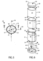
- FIGS. 1-6 show views of a multi-chambered container 20 according to the exemplary embodiments or the present invention.
- container 20 may be formed of several segmented substance-containing chambers which are joined together by suitable conventional means known in the art (to be further described herein) to form a unitary container.
- suitable conventional means known in the art to be further described herein
- container 20 may be provided in which the chambers are formed as integral parts of the container and not as separate components, as further described herein.
- container 20 defines a longitudinal axis LA and includes a top end 22, bottom end 23, and generally vertical container sidewall(s) 21 extending therebetween. Also provided are top closure 24 and bottom closure 25.
- Bottom closure 25 in one embodiment includes a preferably flat horizontal end surface 28 to allow container 20 to stand upright on a horizontal surface for storage and an annular side skirt 29 extending therefrom in an axial direction. End surface 28 defines an outlet or discharge aperture 27 for dispensing flowable substances from container 20.
- Top closure 24 includes an end surface 38 and annular side skirt 39 extending axially therefrom as show. In some embodiments, as shown, top closure 24 may serve to close and seal the top end 52 of uppermost chamber 50.
- container 20 further includes a first chamber 30, second chamber 40, and third chamber 50 in some embodiments.
- the container may have fewer or more chambers.
- container sidewall 21 is collectively defined by the sidewalls 31, 41, 51 of chambers 30, 40, and 50 respectively when the chambers 30, 40, 50 are assembled together.
- Container sidewall 21 may have any suitable and aesthetically pleasing shape or contour.
- container 20 may have any suitable cross-sectional shape which is collectively formed by the cross-sectional sidewall 31, 41, 51 shapes of the chambers 30, 40, 50 including without limitation circular, oval/ellipsoidal, polygonal (e.g. composed of any number and/or orientation of linear segments defining an enclosed space), and combinations thereof.
- sidewall 21 has a generally circular or oval/ellipsoidal shape. Accordingly, it will be appreciated by those skilled in the art that the shape of container 20 need not be uniform in sidewall 21 configuration (as shown in the accompanying figures and exemplary embodiment) and may vary in configuration and dimension from top to bottom in various curved or undulating combinations of shapes.
- Each chamber 30, 40, 50 is a generally hollow structure defining an interior space or cavity C providing volumetric capacity for receiving and storing a flowable substance S1, S2, and S3, respectively.
- Substances S1, S2, and S3 may be similar or different, and in preferred embodiments comprise at least two different substances.
- chamber 30 includes a sidewall 31 having a generally vertical sidewall surface, a top end 32, and a bottom end 33. Top end 32 and bottom end 33 may be opened or closed.
- chambers 40 and 50 may be similarly structured and configured to chamber 30 including, respectively, sideways 41 and 51, top ends 42 and 52, and bottom ends 43 and 53 as shown.
- chambers 30, 40, or 50 may have different shapes and/or dimensions with varying volumetric capacities depending on the overall intended shape of container 20 and container sidewall 21 once all chambers 30,40, 50 are assembled together.
- the thickness of sidewall 31, 41, and 51 may be uniform or non-uniform along the height and/or circumference of each chamber 30, 40, 50 so long as the overall container 20 is self-supporting when placed on a support surface.
- the thickness of the sidewalls is preferably selected so that the chambers 30, 40, 50 may be inwardly and elastically deformed for dispensing flowable substances S1, S2, or S3 when pressed/squeezed by a user, and then return to its original configuration when released. It is well within the ambit of those skilled in the art to select appropriate combinations of materials and thicknesses without undue experimentation to achieve the foregoing functionality.
- container 20 includes generally horizontal or literal internal partition walls 34 and 44 which divide the container into a plurality of separate isolated chambers 30, 40, 50 each capable of holding a flowable substance S1, S2, or S3.
- Partition walls 34, 44 also laterally stiffen container sidewall 21 adjacent the walls to resist deformation for reasons which will become apparent as later described herein.
- Partition walls 34, 44 are coupled to and radially extend from container sidewall 21 inwards in a direction generally transverse (i.e. perpendicularly and/or angularly) to longitudinal axis LA.
- partition walls 34 or 44 may be molded as a separate component part that is attached between adjacent chambers such as partition wall 34 disposed between chambers 30 and 40 as shown (see also FIG. 6 ).
- partition walls 34 or 44 may be formed and molded as an integral part of one of the chambers such as partition wall 44 of chamber 40 which closes the top 42 of the chamber (see also FIG. 6 ). Accordingly, any combination of these constructions may be used for the partition walls.
- partition walls 34, 44 may be configured and adapted to provide headspace HS at the top of each chamber 30, 40, 50.
- container sidewall 21 is made of a transparent or translucent material
- any air trapped in the chambers from the initial substance filling process advantageously will be concealed from the user to provide a more aesthetically pleasing appearance rather than creating a line at the air-substance surface visible from the exterior of the container.
- Partition walls 34, 44 are therefore preferably structured in some embodiments so that a portion of the partition wall defining the headspace HIS extends above and vertically up into the bottom of the adjacent chamber. This positions the vertically-extended portions of each partition wall above the seams 35, 45 between adjacent vertically stacked chambers (see FIG. 2 ).
- partition walls 35, 45 may be configured with a domed portion as shown that provides the headspace HS.
- the headspace HS for the uppermost chamber 50 may be provided by vertically-extended portion of container top closure 24 as shown.
- partition walls 34, 44 contemplates that at least portions of and/or the entirety of these walls may be disposed at various angles to container sidewall 31 and/or may include a plurality of varying contoured and undulating configurations. This includes allowance for the vertically-extended portions of partition walls 34,44 that create the headspace HS as noted above. Accordingly, partition walls 34, 44 are expressly not limited to any particular orientation or configuration so long as one chamber 30, 40, 50 may be isolated from the adjoining chamber.
- container 20 further includes a radially-extending bottom end wall 37 that closes and seals the bottom end 33 of lowermost chamber 30.
- end wall 37 is vertically spaced apart from end surface 28 of bottom closure 25.
- this forms an internal compartment 26 which is bounded by end surface 28 and annular side skirt 29 of bottom closure 23 (see also FIG. 6 ) and opposing end wall 37. This provides internal space for accommodating portions of a dispensing system for container 20 as further described herein.
- a dispensing system that fluidly couples or connects each of the chambers 30, 40, 50 to discharge aperture 27 of container 20.
- the dispensing system is preferably configured and adapted to allow a user to selectively dispense substances S1, S2, or S3.
- a user can select either only one substance of S1, S2, S3 at a time, or more than one substance S1, S2, S3 from their respective chambers. The user selects how many of the substances are to be dispensed. If only one substance is selected, then it is dispensed without being simultaneously mixed with the remaining substances either internal or external to container 20. If more than one substance is selected by the user, then the selected substances will mix external to the container 20.
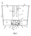
- FIG. 7 is a detailed cross sectional view of the lower portion of container 20 and bottom closure 25 taken through discharge valve assembly 60.
- FIG. 10 is perspective view of one possible arrangement of flow conduits.
- the dispensing, system includes a plurality of flow conduits 80, 90, 100 which fluidly connect chambers 30, 40, and 50 to a common discharge valve assembly 60 disposed in bottom closure 25, which in turn is in fluide communication with discharge aperture 27 in the bottom closure to dispense the selected substance to the user.
- common discharge valve assembly 60 is in fluide communication with all three chambers.
- discharge valve assembly 60 includes an inlet flow manifold 61 (see also FIGS.
- the flow conduits are designed to isolate substances S1, S2, and S3 from each other when dispensed from their respective chamber 30, 40, 50 so the substances do not mix inside the container.
- flow conduit 80 fluidly couples chamber 40 to discharge valve assembly 60.
- flow conduit 80 has an upper end connected to an outlet nipple or fitting 46 on chamber 40 and a lower end connected to discharge valve assembly 60, and more specifically to flow manifold 61 in some embodiments, thereby allowing substance S2 to flow through container 20 while remaining isolated from the other substances.
- flow conduit 80 may be routed internally through chamber 30. In some other possible embodiments, flow conduit 80 may be routed external to and bypass chamber 30. Either arrangement is suitable and a matter of design and aesthetic preference.
- flow conduits 90 fluidly couples chamber 50 to discharge valve assembly 60 and conveys flowable substance S3 in a manner similar to flow conduit 80 described above.
- Flow conduit 90 has an upper end connected to an outlet fitting 56 on chamber 50 and a lower end connected to discharge valve assembly 60, and more specifically to flow manifold 61.
- Flow conduit 100 (best shown in FIG. 10 ) similarly conveys flowable substance S1 and has an upper end connected to an outlet fitting 36 on chamber 30 and a lower end connected to discharge valve assembly 60, and more specifically flow manifold 61 (see FIGS. 6 and 10 ).
- flow conduits 90 and 100 may be routed internally through the chambers 30 and/or 40 of container 20 in some embodiments, and in other possible embodiments flow conduits 90, 100 may be routed external to and bypass chambers 30 and/or 40 as a matter of design and aesthetic preference. Accordingly, it will be appreciated that in some embodiments one or more of flow conduits 80, 90, 100 may be located on the exterior of container 20. The invention is therefore not limited by the placement of flow conduits 80, 90, 100 on either the exterior or in the interior of container 20 so long as the flow conduits preferably may be coupled to discharge valve assembly 60 and more preferably to inlet flow manifold 61.
- tubing channels 110 may be molded into or separately attached to the interior of chambers 30 and 40 for organizing and confining flow conduits 80 and 90 to provide a neat appearance when container 20 is made or a transparent or translucent material.
- Tubing channels 110 may have any suitable lateral cross-sectional shape (viewed perpendicular to longitudinal axis LA) so long as flow conduits 80 and/or 90 may fit and be routed inside.
- channel 110 disposed in chamber 30 has a larger cross-sectional area than the channel in chamber 40 to accommodate both flow conduits 80 and 90 inside and route both conduits through chamber 30 to discharge valve assembly 60 positioned below.
- flow conduits of the dispensing system may comprise both soft flexible and/or relatively rigid plastic tubular conduits and relatively rigid flow fittings including combinations of all of the foregoing types of tubular conduits and fittings.
- flow conduits 80, 90, and 100 may be made of a suitable flexible plastic tubing which can be readily shaped and curved in a routing path between their respective chambers and inlet flow manifold 61 of discharge valve assembly 60.
- the flow fittings, such as chamber outlet fittings 36, 46, 56 for example, are preferably made of a suitable plastic harder and more rigid than the tubing in a conventional manner for securing the tubing thereto. Additional intermediate fittings (i.e.
- flow conduits 80, 90, and 100 may be formed of a rigid plastic tube that may be integrally molded as part of a chambers 30, 40, 50 or as a separate component.
- the coupling between tubing and/or fitting connections may be made by any suitable technique commonly used in the art such as without limitation mechanical couplings (e.g. friction fit, threaded, etc.), ultrasonic welding, adhesives, etc. so long a relatively leak resistant joint is formed.
- discharge valve assembly 60 may be disposed in internal compartment 26 and supported by bottom closure 25.
- Discharge valve assembly 60 preferably communicates with discharge aperture 27 for dispensing user-selected substances S1, S2, or S3 and may be positioned in any suitable location with internal compartment 26 of bottom closure 25.
- Discharge valve assembly 60 includes an inlet flow manifold 61 and a preferably elastomeric valve 63 disposed above and communicating with discharge aperture 27.
- valve 63 is made of silicon; however, any suitable resiliently flexibly elastomeric material may be used.
- valve 63 may have a circular shape in top view and includes an arcuately shaped cross-sectional portion as shown (see FIGS. 6 and 7 ) defining opposing outer concave and inner convex surfaces.
- the arcuately shaped portion includes a flexible slit or slits 115 of any suitable configuration that form flaps capable of resiliently opening to dispense one of the substances S1, S2, or S3 therethrough, and then returning to a closed positions for stopping flow and reducing suckback (i.e. uptake of air back into the container when the user-applied inward pressing or squeezing force is removed from the containers).
- discharge valve 63 preferably functions similarly to a check valve.
- slits 115 may be X-shaped in configuration.
- discharge valve 63 preferably is positioned proximate to and communicates with discharge aperture 27 to minimize any accumulation of substance or product in the container beyond valve 63.
- Discharge valve assembly 60 defines an internal flow mixing reservoir 320 (see FIG. 7 ) in some embodiments which allows two or more flowable substances S1, S2, and S3 to be simultaneously blended or mixed together prior to dispensing through valve 63, as further described herein elsewhere.
- valve 63 may secured in position by integral radially-extending flanges 68 which become compressed between a shoulder bushing 62 (preferably made of an elastomeric or rigid plastic material) and a portion of bottom closure 25 as shown in FIG. 7 when the bottom closure 25 is assembled to container 20.
- Bottom closure 25 may include an annular raised seating surface 111 (best shown in FIG. 7 ) to receive and retain the bushing 62.
- valve assembly 60 including inlet flow manifold 61 may be concentrically aligned with discharge aperture 27.
- valve assembly 60 and discharge aperture 27 are both concentrically and axially aligned with longitudinal axis LA of container to as shown.
- valve assembly 60 and discharge aperture 27 may be positioned off axis with respect to longitudinal axis LA of the container depending on the intended design.
- inlet flow manifold 61 and discharge valve 63 are closely coupled to minimize the length of the flow path therebetween which might otherwise allow for an excessive amount of residual substance or product to accumulate.
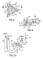
- FIGS. 8-10 show additional views of inlet flow manifold 61 generally disembodied from container 20 for clarity and including flow arrows showing the direction of flow for substances S1, S2, or S3 through the manifold.
- FIG. 8 is a top cross-sectional view through inlet flow manifold 61.
- FIG. 9 is a side or elevational cross-sectional view thereof taken along line 9-9 in FIG. 8 showing the connection to flow conduit 100 which would be located towards the front of container 20 in the embodiment described herein (discharge valve 63 omitted for clarity).
- FIG. 10 is an isometric view of inlet flow manifold 61 showing one possible arrangement of flow conduits 80, 90, and 100 coupled to the manifold.
- a portion of container 20 and chamber 30 are shown in dashed lines to better illustrate one possible placement of outlet fitting 36 on chamber 30 and flow conduit 100 (located towards the front of the container) which is not as readily visible in the other figures.
- inlet flow manifold 61 may be disc or cylindrically shaped and includes an internal cavity 65.
- Manifold 61 includes internal baffles 66 disposed in cavity 65 that function to keep the substances S1, S2, and S3 separated when each of the substances are dispensed from container 20.
- baffles 66 partition cavity 65 off into three internal flow compartments 67 as shown.
- the number of internal flow compartments is equal to the number of chambers provided.
- Baffles 66 have a sufficient longitudinal extent or height selected to prevent lateral substance or product flow entering the inlet flow manifold 61 from flow conduits 80, 90, 100 from entering another opposing flow conduit inlet to be further described herein.
- baffles 66 have height such that the lowest point on the baffle terminates approximately at or below the bottom of inlet fittings 64 as described herein and best shown in FIG. 9 to avoid the foregoing problem.
- each flow conduit 80, 90, 100 or inlet flow manifold 61 may be furnished with a flow restrictor 350 preferably disposed upstream of discharge aperture 27 to ensure that excessive amounts of the substances from each chamber 30, 40, 50 do not seep into the manifold and comingle.
- the flow restrictor 350 may an openable/closeable one-way flexible valve similar to discharge valve 63 or a fixed permanently open reduced diameter flow aperture either of which may be disposed within flow conduits 80, 90, 100 and/or inlet flow manifold 61. In one possible embodiment shown in FIGS.
- the flow restrictor 350 may be an orifice such as a partial height wall or conventional circular orifice plate (not shown) disposed in inlet fitting 64 as shown or elsewhere in flow manifold 61. Accordingly, the flow restrictor 350 may be any suitable valve or orifice structure so long as excessive amounts of flowable substances S1, S2, and S3 are presented from seeping into inlet flow manifold 61. It is well within the ambit of those skilled in the art to select an appropriate one-way valve and/or orifice size based on the viscosity of flowable substances S1, S2, and S3 to accomplish the foregoing functionality.
- Inlet flow manifold 61 further includes a plurality of inlet connections or fittings 64 as best shown in FIGS. 7-10 .
- Inlet fittings 64 extend radially and laterally outward from inlet flow manifold 61 and are configured and adapted for coupling to flow conduits 80, 90, and 100.
- inlet fittings 64 may be radially aligned with the flow manifold axial centerline CL and perpendicular to lateral side 114 (best shown in FIG. 8 ).
- one or more of inlet fittings 64 may be aligned tangentially and/or obliquely to centerline CL and side 114 of manifold 61 in other embodiments depending on the routing of flow conduits 80, 90, 100 if more convenient.
- inlet fittings 64 introduces flow laterally into the flow manifold 61.
- Flow manifold 61 has a single flow outlet 69 as shown which communicates with discharge valve 63 which preferably is positioned closely below the manifold outlet in some embodiments (see FIG. 7 ).
- the number of inlet fittings 64 preferably matches the number of chambers 30, 40, 50 provided.
- inlet flow manifold 61 in this embodiment includes three inlet fittings 64.
- the inlet fittings 64 of flow manifold 61 may be disposed at any suitable position on the outer circumference of inlet flow manifold 61 and separated from each other by any suitable angle dictated at least in part by providing the most efficient arrangement depending on the configuration and routing used for flow conduits 80, 90, and 100.
- the position of each inlet fitting 64 is also dictated by the baffle 66 arrangement provided so that each fitting 64 preferably is located to fluidly communicate with only one of the internal flow compartments 67 as shown in FIGS. 8-10 .
- one or more of the inlet fittings may be located on the top 112 of flow manifold 61 in lieu of on the lateral sides 114 thereof so that flow enters into the manifold from the top.
- These alternate top-entry inlet fittings 64' illustrated in dashed lines in FIG. 9 ) in such an arrangement would be provided such that each inlet fitting still only aligns and communicates with one of the internal flow compartments 67.
- This alternate arrangement allows for close or direct coupling between the lowermost chamber 30 and inlet flow manifold 61 and may be more desirable and/or convenient for connections to the other flow conduits 80 or 90 in some embodiments.
- flow conduit 100 may be eliminated and a top-entry inlet fitting 64' (see, e.g. FIG. 9 ) may be provided to directly connect flow manifold 61 to chamber 30 such as via a flexible elastomeric sealing bushing seated in bottom end wall 37 above the flow manifold inlet fitting 64' (not shown, but readily understandable by those skilled in the art without illustration).
- a top-entry inlet fitting 64' may be provided to directly connect flow manifold 61 to chamber 30 such as via a flexible elastomeric sealing bushing seated in bottom end wall 37 above the flow manifold inlet fitting 64' (not shown, but readily understandable by those skilled in the art without illustration).
- inlet fittings 64 on manifold 61 may include conventional annular tubing barbs as shown in FIGS. 8 and 9 to help secure the connections to flow conduits 80, 90, 100 in the situation where at least the portion of these flow conduits immediately upstream of flow manifold 61 are formed of flexible tubing.
- Other suitable conventional inlet fitting configurations may be provided depending on the type of flow conduit connections that are required to be made.
- flow conduits 80, 90, 100 may be located and routed in any suitable manner through container 20. Accordingly, the invention is not limited to any particular placement or configuration of the flow conduits so long as they may fluidly connect to chambers 30, 40, 50 and terminate at inlet flow manifold 61 of valve assembly 60.
- valve assembly 60 and inlet flow manifold 61 are contemplated and possible for valve assembly 60 and inlet flow manifold 61 so long as the flow conduits from each chamber 30, 40, 50 may be fluidly coupled to the valve assembly each corresponding substance S1, S2, or S3 may selectively discharged from container 20 without dispensing the non-selected substances. Accordingly, the valve assembly and inlet manifold 61 are not limited to the configurations shown and described herein.
- a multi-chambered container 20 is preferably formed of a material that is at least partially flexible/resilient with a shape memory so as to be non-permanently and elastically deformable by a user when applying an inward pressing or squeezing force F to dispense the contents of one of the chambers 30, 40, 50.
- the material will then allow the squeezed container to return to its original shape when the force is removed.
- container 20 may be made of any suitable conventional thermoplastic material commonly used in the art so long as the material has the mechanical properties that allow it to deform temporarily when squeezed by a user, and then return to its original unreformed shape.
- thermoplastic examples include, without limitation, polypropylenes (PP), polyethylenes (PE), polyethylene terephthalate (PET/PETE), polystyrenes (PS), polycarbonate, etc.
- PP polypropylenes
- PE polyethylenes
- PET/PETE polyethylene terephthalate
- PS polystyrenes
- the material selected for the multi-chambered container has properties of being transparent or translucent to allow the product and its color stored inside to be seen by the user.
- Multi-chambered container 20 may be constructed in various suitable manners.
- chambers 30, 40, 50 of the multi-chambered container may each be individually molded separately and then joined together by any suitable means commonly used in the art to form a unitary container such as without limitation ultrasonic welding, adhesives, mechanical coupling such as snap locking, shrink or press fitting, etc.
- chambers 30, 40 50 may be molded and formed as integral parts of a single larger container 20 fabricated together in one or more steps. Accordingly, the present invention contemplates at least both foregoing possible types of the fabrication techniques for container 20 and chambers 30, 40, 50, and is not limited to either.
- the multi-chambered container 20 and chambers 30, 40, 50 may be formed by any conventional suitable means used in the art such as blow molding, injection molding, or vacuum forming as some non-limiting examples.
- FIG. 14 is a flow chart summarizing the flowable substance dispensing steps which follow.
- a single flowable substance dispensing operating mode of the container 20 is first described.
- a user To dispense one of the flowable substance S1, S2, or S3 from container 20 (FIG. 14, step 400), a user first selects which substance is desired to be dispensed (FIG. 14, step 402).
- the user then applies an inward squeezing or pressing force F on the flexible sidewall of chamber 30,40, or 50 (FIG. 14, step 404) corresponding to the selected substance (see, e.g. FIGS. 3 and 5 ).
- the inward pressing force F is preferably applied in a direction toward the longitudinal axis LA (or axial centerline of the container), but need not necessarily be applied precisely in that direction to dispense the selected substance.
- the container has a crows-sectional shape (i.e. when viewed perpendicular to longitudinal axis LA) with a larger dimension along one lateral or radial axis (e.g. axis R2 in FIG. 5 ) than along another second radial axis (e.g.
- the larger container sidewall 21 portion along axis R2 will be somewhat structurally weaker than the shorter container sidewall 21 portion along axis R1 and more flexible. Accordingly, a user may preferably apply the inward pressing force F in the general direction of radial axis R1 by pressing or squeezing somewhere along the larger container sidewall 21 side.
- the shorter side of the container along the R1 axis is preferably structured to be sufficiently flexible so that the user may apply a radial inward force F anywhere along the circumference of sidewall 21 to dispense the selected flowable substance.
- actuation of container 20 to dispense flowable substances S1, S2, and/or S3 may be accomplished by the application of numerous different squeezing or pressing forces F on the container sidewalls 21 so long as one or more of chambers 30, 40, 50 are pressurized.
- a user may select more than one flowable substances S1, S2, S3 for dispensing simultaneously by applying an inward pressing force F on more than chambers 30, 40, 50 at the same time (FIG. 14, step 408).
- a user may simultaneously apply a force F on chambers 30 and 40, 30 and 50, 40 and 50, or 30, 40, and 50 to simultaneously dispense multiple substances S1, S2, and S3 (FIG. 14, step 410).
- the same foregoing dispensing methodology may be applied to selectively dispense multiple substances S1, S2, and S3.
- exemplary methods of using container 20 according to present invention advantageously enables a user to create custom mixes or blends of substances S1, S2, and S3.
- S1 may contain a skin exfoliating formulation
- S2 may contain a vitamin enriched skin-nourishing formulation
- S3 may contain a moisturizing formula.
- a single one of these S1, S2, or S3 formulations may be dispensed (FIG. 14, steps 404 and 406) or custom blends of any two or more of these formulations may be simultaneously dispensed together and blended (FIG. 14, steps 408 and 410) thereby advantageously combining the benefits and properties of each respective formulation selected.
- this latter multiple substance custom blending and dispensing operating mode is advantageously provided by multi-chambered container 20 according to the present invention.
- the flexible sidewall 31, 41, or 51 corresponding to the user-selected chamber 30, 40, or 50 will deform elastically inwards and be pressured by the reduction in volumetric capacity when inward force F is applied by the user.
- Substance S1, S2, or S3 corresponding to the selected chamber will therefore be selectively discharged and flow into its respective flow conduit 80, 90, or 100 without simultaneously dispensing the remaining non-selected substances.
- the lateral partition walls 34 and 44, which separate the chambers 30, 40, 50 see FIG.
- the selected substance S1, S2, or S3 will flow downwards through the container in its respective flow conduit 80, 90, 100 (bypassing the non-selected chambers) and into the corresponding inlet fitting 64 on inlet flow manifold 61.
- the selected substance S1, S2, or S3 will enter flow manifold 61 (in a lateral direction perpendicular to the longitudinal axis LA in some embodiments), and then change path to flow in an axial direction (see FIG. 9 ).
- Substance S1, S2, or S3 will then leave flow manifold 61 through outlet 69 and be dispensed through discharge valve 63 which opens for a period of time corresponding to the application of inward pressing force F on container 20.
- Discharge valve 63 recloses and the substance S1, S2, or S3 will cease being dispensed.
- FIG. 11 shows a variation of a discharge valve assembly 200 for use with multi-chambered container 20 according to principles of the present invention.
- a discharge valve assembly 200 includes separate discharge valves 201, 202, and 203 as shown, which in one embodiment may be similar to valve 63 already described herein.
- Flow conduits 80 and 90 from chambers 40 and 50 respectively may be connected to inlet fittings 204, 205 disposed on bottom end wall 37 of container 20.
- an orifice 206 may simply be provided in bottom end wall 37 which communicates with chamber 30 allowing the passage of substance S1 directly from the chamber to discharge valve 202.
- baffles 207 are preferably provided to keep flowable substances S1, S2, and S3 separate upon discharge from container 20.
- baffles 207 may be formed as part of a collar assembly 208 which is a separate unit insertable into and attachable to bottom closure 25. Collar assembly 208 may be of any suitable configuration so long as the flowable substances may be kept separated without mixing.
- flowable substances S1, S2, and S3 need not be dispensed or discharged from each chamber 30, 40, 50 at the bottom end 23 of the container, in a common direction, or from a common end or single location alone as shown and described herein in some embodiments.
- a valve assembly similar to without limitation 61 or 200 including three separate discharge valves 63 or 201-203, respectively), or of other suitable similar design, may instead be located at the top end 22 each chamber 30, 40, 50 using a dispensing system including flow conduits such as without limitation those similar to 80,90, and 100 described herein.
- At least some of the chambers 30, 40, 50 may dispense their respective flowable substances S1, S2, or S3 from different locations and/or in different directions from each other.
- Such embodiments may include separate discharge apertures 27 each with an associated discharge valve 63 disposed at different locations on container 20 and chambers 30, 40, 50. It is readily within the ambit of those skilled in the art to reverse the location of the discharge valve assemblies to top end 22, or to locate one or more discharge valve assemblies on container 20 based on the description and principles already provided herein without additional discussion.
- the dispensing method may have been described herein for convenience assuming the container 20 is preferably held in a generally vertical orientation, it is possible to dispense substances S1, S2, or S3 with the container held in any suitable position including horizontally if desired. The substances, however, will be most effectively dispensed if the user holds container 20 anywhere from horizontal to vertical, and any position therebetween. Accordingly, the invention is not limited to any particular orientation of the multi-chambered container when the user dispenses the substance or product.
Landscapes
- Engineering & Computer Science (AREA)
- Mechanical Engineering (AREA)
- Ceramic Engineering (AREA)
- Containers And Packaging Bodies Having A Special Means To Remove Contents (AREA)
- Package Specialized In Special Use (AREA)
- Packging For Living Organisms, Food Or Medicinal Products That Are Sensitive To Environmental Conditiond (AREA)
- Bag Frames (AREA)
- Closures For Containers (AREA)
- Medical Preparation Storing Or Oral Administration Devices (AREA)
- Infusion, Injection, And Reservoir Apparatuses (AREA)
Applications Claiming Priority (2)
| Application Number | Priority Date | Filing Date | Title |
|---|---|---|---|
| US12/612,391 US8550303B2 (en) | 2009-11-04 | 2009-11-04 | Multi-chambered container |
| PCT/US2009/063373 WO2011056173A1 (en) | 2009-11-04 | 2009-11-05 | Multi-chambered container |
Publications (2)
| Publication Number | Publication Date |
|---|---|
| EP2496488A1 EP2496488A1 (en) | 2012-09-12 |
| EP2496488B1 true EP2496488B1 (en) | 2014-10-08 |
Family
ID=42169485
Family Applications (1)
| Application Number | Title | Priority Date | Filing Date |
|---|---|---|---|
| EP09748675.7A Not-in-force EP2496488B1 (en) | 2009-11-04 | 2009-11-05 | Multi-chambered container |
Country Status (15)
| Country | Link |
|---|---|
| US (1) | US8550303B2 (enExample) |
| EP (1) | EP2496488B1 (enExample) |
| KR (1) | KR101412367B1 (enExample) |
| CN (1) | CN102639403B (enExample) |
| AU (1) | AU2009354957B2 (enExample) |
| BR (1) | BR112012010276A2 (enExample) |
| CA (1) | CA2776947C (enExample) |
| ES (1) | ES2525546T3 (enExample) |
| IN (1) | IN2012DN02875A (enExample) |
| MA (1) | MA33673B1 (enExample) |
| MX (1) | MX2012004322A (enExample) |
| PH (1) | PH12012500763A1 (enExample) |
| RU (1) | RU2508236C2 (enExample) |
| WO (1) | WO2011056173A1 (enExample) |
| ZA (1) | ZA201202861B (enExample) |
Families Citing this family (30)
| Publication number | Priority date | Publication date | Assignee | Title |
|---|---|---|---|---|
| DE202007004662U1 (de) * | 2007-03-28 | 2008-08-07 | Geiberger, Christoph | Mehrkammerbehälter |
| GB2489409B (en) * | 2011-03-23 | 2013-05-15 | Kraft Foods R & D Inc | A capsule and a system for, and a method of, preparing a beverage |
| US9027790B2 (en) | 2012-10-19 | 2015-05-12 | Gojo Industries, Inc. | Dispensers for diluting a concentrated liquid and dispensing the diluted concentrate |
| AU2012392554B2 (en) * | 2012-10-19 | 2015-08-06 | Colgate-Palmolive Company | Multi-chambered container |
| WO2014077838A1 (en) | 2012-11-19 | 2014-05-22 | Colgate-Palmolive Company | Multi-chamber container |
| US9409695B2 (en) | 2012-11-19 | 2016-08-09 | Colgate-Palmolive Company | Multi-chamber container |
| US9597698B2 (en) | 2012-11-19 | 2017-03-21 | Colgate-Palmolive Company | Multi-chamber container |
| US9409696B2 (en) | 2012-11-19 | 2016-08-09 | Colgate-Palmolive Company | Multi-chamber container |
| WO2014077843A1 (en) | 2012-11-19 | 2014-05-22 | Colgate-Palmolive Company | Multi-chamber container |
| EP2978461B1 (en) * | 2013-03-29 | 2024-07-24 | Givaudan SA | Olfactory device |
| USD733455S1 (en) | 2013-11-20 | 2015-07-07 | Nse Products, Inc. | Fluid cartridge assembly |
| USD731203S1 (en) | 2013-11-20 | 2015-06-09 | Nse Products, Inc. | Fluid cartridge |
| USD730077S1 (en) | 2013-11-20 | 2015-05-26 | Nse Products, Inc. | Fluid dispenser |
| USD731204S1 (en) | 2013-11-20 | 2015-06-09 | Nse Products, Inc. | Fluid cartridge |
| US9346602B2 (en) | 2014-01-20 | 2016-05-24 | Joshua Gitta | Cocktail glass |
| WO2016029104A1 (en) | 2014-08-22 | 2016-02-25 | Nse Products, Inc. | Selectively actuated fluid dispenser |
| US11242236B2 (en) | 2015-03-19 | 2022-02-08 | Phillip LaBarbera | Perfect pour drink mixer |
| US11613420B2 (en) * | 2015-03-25 | 2023-03-28 | Shakesphere Products Limited | Tumbler bottle |
| AU2015100381A4 (en) * | 2015-03-25 | 2015-04-30 | Sports Creative Limited | A sports and/or mixing bottle |
| WO2017004102A1 (en) | 2015-06-29 | 2017-01-05 | The Procter & Gamble Company | Multi-component skin care product comprising nicoinamide riboside in a multi-chambered container |
| KR102114892B1 (ko) | 2016-01-11 | 2020-05-26 | 더 프록터 앤드 갬블 캄파니 | 피부 상태의 치료 방법 및 그를 위한 조성물 |
| US10279989B2 (en) | 2016-05-06 | 2019-05-07 | Baker Hughes, A Ge Company, Llc | Stackable container system, operating system using container system, and method |
| EP3641725A1 (en) | 2017-06-23 | 2020-04-29 | The Procter and Gamble Company | Composition and method for improving the appearance of skin |
| CN108455000B (zh) * | 2018-01-19 | 2020-06-02 | 汕头市大西洋塑料制品有限公司 | 一种按压式出药试剂瓶 |
| KR20210016457A (ko) | 2018-06-01 | 2021-02-15 | 인 스피릿 그룹, 인크. | 다중-구획 음료 용기 시스템 및 방법 |
| FR3081847B1 (fr) * | 2018-06-05 | 2021-08-27 | Coradin Sas | Dispositif pour emballer au moins un premier et un deuxieme fluide |
| US11622963B2 (en) | 2018-07-03 | 2023-04-11 | The Procter & Gamble Company | Method of treating a skin condition |
| US10959933B1 (en) | 2020-06-01 | 2021-03-30 | The Procter & Gamble Company | Low pH skin care composition and methods of using the same |
| CN115843238B (zh) | 2020-06-01 | 2025-06-10 | 宝洁公司 | 改善维生素b3化合物渗透到皮肤中的方法 |
| KR102869166B1 (ko) * | 2022-11-09 | 2025-10-14 | (주)코앤코 | 화학약품 용기 |
Family Cites Families (55)
| Publication number | Priority date | Publication date | Assignee | Title |
|---|---|---|---|---|
| US704105A (en) * | 1901-11-29 | 1902-07-08 | Ellis D Read | Bottle or flask. |
| US1535529A (en) | 1921-06-11 | 1925-04-28 | Hopkins Nevil Monroe | Collapsible tube |
| US3269389A (en) | 1963-03-11 | 1966-08-30 | Bernard L Meurer | Compartmental dispensing container for nose and throat preparations |
| US3518018A (en) * | 1968-01-29 | 1970-06-30 | Raymond A Woods | Carpet color retouching kit |
| US3506157A (en) * | 1968-12-11 | 1970-04-14 | Joseph Dukess | Pronged closure device for multiple compartment squeeze tube |
| US3876112A (en) * | 1974-01-07 | 1975-04-08 | Steven G Kramer | Multicompartmented squeezable bottle with selective dispensing |
| US4029236A (en) * | 1976-05-17 | 1977-06-14 | Colgate-Palmolive Company | Two product dispenser with cooperating telescoping cylinders |
| CH658636A5 (fr) * | 1983-11-02 | 1986-11-28 | Serge Michielin | Dispositif d'obturation etanche adaptable a toute forme d'emballage ou appareillage contenant des fluides. |
| GB8615670D0 (en) | 1986-06-26 | 1986-07-30 | Beecham Group Plc | Device |
| DE4003921A1 (de) | 1990-02-09 | 1990-06-21 | Richard Sirotzki | Doppelseitige tube |
| US5062550A (en) | 1990-05-24 | 1991-11-05 | Singh Bharat H | Selective flow dispensing container |
| US5154917A (en) * | 1990-09-11 | 1992-10-13 | Beecham Inc. | Color change mouthrinse |
| US5269441A (en) | 1992-01-31 | 1993-12-14 | Cp Packaging, Inc., Sub. Of Wheaton Industries | Dual chamber medicament dispenser having a pleated common wall |
| US5356040A (en) | 1992-03-31 | 1994-10-18 | Maplast S.R.L. | Container particulary for multicomponent products |
| US5318203A (en) | 1993-07-01 | 1994-06-07 | Chesebrough-Pond's Usa Co., Division Of Conopco, Inc. | Dual chamber dispenser |
| US5462526A (en) | 1993-09-15 | 1995-10-31 | Mcgaw, Inc. | Flexible, sterile container and method of making and using same |
| SE9303453D0 (sv) | 1993-10-20 | 1993-10-20 | Kabi Pharmacia Ab | Injection cartridge |
| GB9325944D0 (en) | 1993-12-18 | 1994-02-23 | Smith & Nephew | Dual packaging systems |
| US5725499A (en) | 1994-05-11 | 1998-03-10 | Plas-Pak Industries, Inc. | Dual barreled syringe and methods of assembly and use |
| DE4428096A1 (de) | 1994-08-09 | 1996-02-15 | Wella Ag | Zweikammerbehälter |
| JPH08164954A (ja) | 1994-12-15 | 1996-06-25 | Yoshida Kogyo Kk <Ykk> | チューブ容器 |
| US5628429A (en) | 1995-11-22 | 1997-05-13 | Enamelon, Inc. | Plural chambered squeezable dispensing tube |
| FR2751942B1 (fr) | 1996-08-02 | 1998-09-11 | Oreal | Dispositif pour le stockage separe de deux composants leur melange et la distibution du melange |
| US5794819A (en) * | 1996-08-13 | 1998-08-18 | Smith; Trevor A. | Dual-compartment bottle system |
| US6113257A (en) | 1996-12-26 | 2000-09-05 | M.L.I.S. Projects Ltd. | Two-compartment container |
| US5865345A (en) | 1996-12-31 | 1999-02-02 | Lawson Mardon Wheaton Inc. | Container for dispensing two substances |
| US6082588A (en) | 1997-01-10 | 2000-07-04 | Lever Brothers Company, Division Of Conopco, Inc. | Dual compartment package and pumps |
| US5921440A (en) * | 1997-09-03 | 1999-07-13 | Maines; Morris P. | Multi-compartment container and adjustable dispenser |
| US6223942B1 (en) | 1998-07-28 | 2001-05-01 | Lever Brothers Company, Division Of Conopco, Inc. | Container and closure |
| US6419783B1 (en) | 1999-04-16 | 2002-07-16 | Unilever Home & Personal Care Usa | Container and closure |
| US6247617B1 (en) * | 1999-12-13 | 2001-06-19 | Richard Allen Clyde | Single use container for dispensing separately housed sterile compositions |
| US6179146B1 (en) | 1999-12-15 | 2001-01-30 | Betras Plastics, Inc. | Double chambered container |
| US6223943B1 (en) | 2000-02-07 | 2001-05-01 | Bristol-Meyers Squibb Company | Method and apparatus for molding multichamber squeeze tubes and tubes produced thereby |
| US6276571B1 (en) * | 2000-06-16 | 2001-08-21 | Kody Clemmons | Fuel dispensing system |
| FR2811636B1 (fr) | 2000-07-17 | 2002-09-20 | Oreal | Dispositif pour le conditionnement separe de deux ou trois composants a melanger extemporanement |
| US6299023B1 (en) * | 2000-08-24 | 2001-10-09 | Miles Arnone | Device for dispensing two substances in a user selectable ratio with replaceable cartridges |
| US6325229B1 (en) | 2001-02-20 | 2001-12-04 | Stuart Anders | Container coil having multiple discreet compartments |
| KR200258608Y1 (ko) | 2001-10-08 | 2001-12-29 | 고려알파라인(주) | 다단식 밀폐형 용기 |
| US6749090B2 (en) * | 2001-10-22 | 2004-06-15 | Trek Bicycle Corporation | Dual bladder sports hydration system |
| US6752264B2 (en) * | 2002-07-03 | 2004-06-22 | Sonoco Development, Inc. | Flexible pouch having system for mixing two components |
| US7448556B2 (en) | 2002-08-16 | 2008-11-11 | Henkel Kgaa | Dispenser bottle for at least two active fluids |
| GB0223981D0 (en) | 2002-10-16 | 2002-11-20 | Singh Manjit C N | Beverage bottles |
| DE202005002331U1 (de) | 2004-02-18 | 2005-05-12 | Günterberg, Monika | Behälter zur Aufbewahrung von Getränken, Kosmetika, Reinigungsmitteln und anderen Verbrauchsgütern |
| US7617950B2 (en) * | 2004-05-24 | 2009-11-17 | Colgate-Palmolive Company | Controlling flow from multi-chamber containers |
| US20060021996A1 (en) * | 2004-07-30 | 2006-02-02 | Scott L J Iii | Multi-chambered drink bottle |
| CA2514690C (en) | 2004-08-09 | 2013-01-29 | Gotohti.Com Inc. | Multiple compartment collapsible bottle |
| US7258251B2 (en) | 2004-08-25 | 2007-08-21 | Juan Perez Johnson | Multi-chambered dispensing container |
| US7581899B2 (en) | 2004-11-30 | 2009-09-01 | James Alexander Corporation | Dispenser and process |
| US20060175350A1 (en) * | 2005-02-09 | 2006-08-10 | Abramson Andrew F | Multi-compartment container |
| US7487888B1 (en) * | 2005-07-15 | 2009-02-10 | Pierre Jr Lloyd A | Fluid dispensing apparatus |
| JP5118838B2 (ja) * | 2006-03-31 | 2013-01-16 | 株式会社大塚製薬工場 | 複室容器 |
| US7976234B2 (en) * | 2006-04-28 | 2011-07-12 | James Alexander Corporation | Multi-chambered dispenser and process |
| US7793667B2 (en) | 2006-08-11 | 2010-09-14 | Gayton Karen L | Method and device for applying hair color |
| US8074825B1 (en) * | 2007-09-04 | 2011-12-13 | Ziegler Robert A | Dispensing closure for selectively dispensing material from a multi-chambered container |
| US8376183B1 (en) * | 2008-06-10 | 2013-02-19 | Ags I-Prop, Llc | Fluid dispenser having multiple chambers |
-
2009
- 2009-11-04 US US12/612,391 patent/US8550303B2/en not_active Expired - Fee Related
- 2009-11-05 CN CN200980162371.7A patent/CN102639403B/zh not_active Expired - Fee Related
- 2009-11-05 EP EP09748675.7A patent/EP2496488B1/en not_active Not-in-force
- 2009-11-05 PH PH1/2012/500763A patent/PH12012500763A1/en unknown
- 2009-11-05 CA CA2776947A patent/CA2776947C/en not_active Expired - Fee Related
- 2009-11-05 ES ES09748675.7T patent/ES2525546T3/es active Active
- 2009-11-05 IN IN2875DEN2012 patent/IN2012DN02875A/en unknown
- 2009-11-05 KR KR1020127014024A patent/KR101412367B1/ko not_active Expired - Fee Related
- 2009-11-05 AU AU2009354957A patent/AU2009354957B2/en not_active Ceased
- 2009-11-05 WO PCT/US2009/063373 patent/WO2011056173A1/en not_active Ceased
- 2009-11-05 BR BR112012010276A patent/BR112012010276A2/pt not_active IP Right Cessation
- 2009-11-05 MX MX2012004322A patent/MX2012004322A/es active IP Right Grant
- 2009-11-05 RU RU2012122810/12A patent/RU2508236C2/ru not_active IP Right Cessation
-
2012
- 2012-04-13 MA MA34777A patent/MA33673B1/fr unknown
- 2012-04-18 ZA ZA2012/02861A patent/ZA201202861B/en unknown
Also Published As
| Publication number | Publication date |
|---|---|
| KR20120079168A (ko) | 2012-07-11 |
| MA33673B1 (fr) | 2012-10-01 |
| CN102639403B (zh) | 2014-06-25 |
| RU2508236C2 (ru) | 2014-02-27 |
| US8550303B2 (en) | 2013-10-08 |
| AU2009354957A1 (en) | 2012-05-10 |
| CA2776947A1 (en) | 2011-05-12 |
| BR112012010276A2 (pt) | 2016-03-29 |
| HK1174598A1 (en) | 2013-06-14 |
| CA2776947C (en) | 2014-02-18 |
| ZA201202861B (en) | 2014-10-29 |
| MX2012004322A (es) | 2012-05-08 |
| WO2011056173A1 (en) | 2011-05-12 |
| US20110101021A1 (en) | 2011-05-05 |
| AU2009354957B2 (en) | 2014-02-06 |
| CN102639403A (zh) | 2012-08-15 |
| IN2012DN02875A (enExample) | 2015-07-24 |
| ES2525546T3 (es) | 2014-12-26 |
| PH12012500763A1 (en) | 2012-11-26 |
| RU2012122810A (ru) | 2013-12-10 |
| KR101412367B1 (ko) | 2014-06-25 |
| EP2496488A1 (en) | 2012-09-12 |
Similar Documents
| Publication | Publication Date | Title |
|---|---|---|
| CA2776947C (en) | Multi-chambered container | |
| CN101746567B (zh) | 带单向阀的双软管容器 | |
| KR20030007576A (ko) | 다중 격실 컨테이너 | |
| AU2006299152B2 (en) | Method and assembly for dispensing a product from a form-retaining container | |
| US9540149B2 (en) | Multi-chambered container | |
| CN107810143A (zh) | 制造活塞气溶胶分配器的方法 | |
| EP2281755B1 (en) | Liquid mixing chamber | |
| WO1999006296A1 (en) | Dispensing tube and valve assembly | |
| ES2402049T3 (es) | Recipiente distribuidor multicámara | |
| US20040206775A1 (en) | Container with divided compartments | |
| CN102107752B (zh) | 一种防回流双腔软管 | |
| HK1174598B (en) | Multi-chambered container | |
| CN104755385A (zh) | 直立挤压发泡器 | |
| CN112974029B (zh) | 分配头 | |
| KR20250084580A (ko) | 토출용기 | |
| MXPA00001356A (en) | Multichamber dispensing container |
Legal Events
| Date | Code | Title | Description |
|---|---|---|---|
| PUAI | Public reference made under article 153(3) epc to a published international application that has entered the european phase |
Free format text: ORIGINAL CODE: 0009012 |
|
| 17P | Request for examination filed |
Effective date: 20120518 |
|
| AK | Designated contracting states |
Kind code of ref document: A1 Designated state(s): AT BE BG CH CY CZ DE DK EE ES FI FR GB GR HR HU IE IS IT LI LT LU LV MC MK MT NL NO PL PT RO SE SI SK SM TR |
|
| DAX | Request for extension of the european patent (deleted) | ||
| REG | Reference to a national code |
Ref country code: HK Ref legal event code: DE Ref document number: 1174598 Country of ref document: HK |
|
| GRAP | Despatch of communication of intention to grant a patent |
Free format text: ORIGINAL CODE: EPIDOSNIGR1 |
|
| INTG | Intention to grant announced |
Effective date: 20140605 |
|
| GRAS | Grant fee paid |
Free format text: ORIGINAL CODE: EPIDOSNIGR3 |
|
| GRAA | (expected) grant |
Free format text: ORIGINAL CODE: 0009210 |
|
| AK | Designated contracting states |
Kind code of ref document: B1 Designated state(s): AT BE BG CH CY CZ DE DK EE ES FI FR GB GR HR HU IE IS IT LI LT LU LV MC MK MT NL NO PL PT RO SE SI SK SM TR |
|
| REG | Reference to a national code |
Ref country code: GB Ref legal event code: FG4D |
|
| REG | Reference to a national code |
Ref country code: AT Ref legal event code: REF Ref document number: 690437 Country of ref document: AT Kind code of ref document: T Effective date: 20141015 Ref country code: CH Ref legal event code: EP |
|
| REG | Reference to a national code |
Ref country code: IE Ref legal event code: FG4D |
|
| REG | Reference to a national code |
Ref country code: DE Ref legal event code: R096 Ref document number: 602009027082 Country of ref document: DE Effective date: 20141120 |
|
| REG | Reference to a national code |
Ref country code: ES Ref legal event code: FG2A Ref document number: 2525546 Country of ref document: ES Kind code of ref document: T3 Effective date: 20141226 |
|
| REG | Reference to a national code |
Ref country code: NL Ref legal event code: VDEP Effective date: 20141008 |
|
| REG | Reference to a national code |
Ref country code: AT Ref legal event code: MK05 Ref document number: 690437 Country of ref document: AT Kind code of ref document: T Effective date: 20141008 |
|
| REG | Reference to a national code |
Ref country code: LT Ref legal event code: MG4D |
|
| PG25 | Lapsed in a contracting state [announced via postgrant information from national office to epo] |
Ref country code: NL Free format text: LAPSE BECAUSE OF FAILURE TO SUBMIT A TRANSLATION OF THE DESCRIPTION OR TO PAY THE FEE WITHIN THE PRESCRIBED TIME-LIMIT Effective date: 20141008 |
|
| PG25 | Lapsed in a contracting state [announced via postgrant information from national office to epo] |
Ref country code: LT Free format text: LAPSE BECAUSE OF FAILURE TO SUBMIT A TRANSLATION OF THE DESCRIPTION OR TO PAY THE FEE WITHIN THE PRESCRIBED TIME-LIMIT Effective date: 20141008 Ref country code: PT Free format text: LAPSE BECAUSE OF FAILURE TO SUBMIT A TRANSLATION OF THE DESCRIPTION OR TO PAY THE FEE WITHIN THE PRESCRIBED TIME-LIMIT Effective date: 20150209 Ref country code: FI Free format text: LAPSE BECAUSE OF FAILURE TO SUBMIT A TRANSLATION OF THE DESCRIPTION OR TO PAY THE FEE WITHIN THE PRESCRIBED TIME-LIMIT Effective date: 20141008 Ref country code: NO Free format text: LAPSE BECAUSE OF FAILURE TO SUBMIT A TRANSLATION OF THE DESCRIPTION OR TO PAY THE FEE WITHIN THE PRESCRIBED TIME-LIMIT Effective date: 20150108 Ref country code: IS Free format text: LAPSE BECAUSE OF FAILURE TO SUBMIT A TRANSLATION OF THE DESCRIPTION OR TO PAY THE FEE WITHIN THE PRESCRIBED TIME-LIMIT Effective date: 20150208 |
|
| PG25 | Lapsed in a contracting state [announced via postgrant information from national office to epo] |
Ref country code: GR Free format text: LAPSE BECAUSE OF FAILURE TO SUBMIT A TRANSLATION OF THE DESCRIPTION OR TO PAY THE FEE WITHIN THE PRESCRIBED TIME-LIMIT Effective date: 20150109 Ref country code: PL Free format text: LAPSE BECAUSE OF FAILURE TO SUBMIT A TRANSLATION OF THE DESCRIPTION OR TO PAY THE FEE WITHIN THE PRESCRIBED TIME-LIMIT Effective date: 20141008 Ref country code: AT Free format text: LAPSE BECAUSE OF FAILURE TO SUBMIT A TRANSLATION OF THE DESCRIPTION OR TO PAY THE FEE WITHIN THE PRESCRIBED TIME-LIMIT Effective date: 20141008 Ref country code: SE Free format text: LAPSE BECAUSE OF FAILURE TO SUBMIT A TRANSLATION OF THE DESCRIPTION OR TO PAY THE FEE WITHIN THE PRESCRIBED TIME-LIMIT Effective date: 20141008 Ref country code: HR Free format text: LAPSE BECAUSE OF FAILURE TO SUBMIT A TRANSLATION OF THE DESCRIPTION OR TO PAY THE FEE WITHIN THE PRESCRIBED TIME-LIMIT Effective date: 20141008 Ref country code: LV Free format text: LAPSE BECAUSE OF FAILURE TO SUBMIT A TRANSLATION OF THE DESCRIPTION OR TO PAY THE FEE WITHIN THE PRESCRIBED TIME-LIMIT Effective date: 20141008 Ref country code: CY Free format text: LAPSE BECAUSE OF FAILURE TO SUBMIT A TRANSLATION OF THE DESCRIPTION OR TO PAY THE FEE WITHIN THE PRESCRIBED TIME-LIMIT Effective date: 20141008 |
|
| PG25 | Lapsed in a contracting state [announced via postgrant information from national office to epo] |
Ref country code: BE Free format text: LAPSE BECAUSE OF NON-PAYMENT OF DUE FEES Effective date: 20141130 |
|
| REG | Reference to a national code |
Ref country code: CH Ref legal event code: PL |
|
| REG | Reference to a national code |
Ref country code: DE Ref legal event code: R097 Ref document number: 602009027082 Country of ref document: DE |
|
| PG25 | Lapsed in a contracting state [announced via postgrant information from national office to epo] |
Ref country code: CZ Free format text: LAPSE BECAUSE OF FAILURE TO SUBMIT A TRANSLATION OF THE DESCRIPTION OR TO PAY THE FEE WITHIN THE PRESCRIBED TIME-LIMIT Effective date: 20141008 Ref country code: LI Free format text: LAPSE BECAUSE OF NON-PAYMENT OF DUE FEES Effective date: 20141130 Ref country code: SK Free format text: LAPSE BECAUSE OF FAILURE TO SUBMIT A TRANSLATION OF THE DESCRIPTION OR TO PAY THE FEE WITHIN THE PRESCRIBED TIME-LIMIT Effective date: 20141008 Ref country code: EE Free format text: LAPSE BECAUSE OF FAILURE TO SUBMIT A TRANSLATION OF THE DESCRIPTION OR TO PAY THE FEE WITHIN THE PRESCRIBED TIME-LIMIT Effective date: 20141008 Ref country code: RO Free format text: LAPSE BECAUSE OF FAILURE TO SUBMIT A TRANSLATION OF THE DESCRIPTION OR TO PAY THE FEE WITHIN THE PRESCRIBED TIME-LIMIT Effective date: 20141008 Ref country code: CH Free format text: LAPSE BECAUSE OF NON-PAYMENT OF DUE FEES Effective date: 20141130 Ref country code: DK Free format text: LAPSE BECAUSE OF FAILURE TO SUBMIT A TRANSLATION OF THE DESCRIPTION OR TO PAY THE FEE WITHIN THE PRESCRIBED TIME-LIMIT Effective date: 20141008 Ref country code: MC Free format text: LAPSE BECAUSE OF FAILURE TO SUBMIT A TRANSLATION OF THE DESCRIPTION OR TO PAY THE FEE WITHIN THE PRESCRIBED TIME-LIMIT Effective date: 20141008 |
|
| PLBE | No opposition filed within time limit |
Free format text: ORIGINAL CODE: 0009261 |
|
| STAA | Information on the status of an ep patent application or granted ep patent |
Free format text: STATUS: NO OPPOSITION FILED WITHIN TIME LIMIT |
|
| REG | Reference to a national code |
Ref country code: IE Ref legal event code: MM4A |
|
| 26N | No opposition filed |
Effective date: 20150709 |
|
| PG25 | Lapsed in a contracting state [announced via postgrant information from national office to epo] |
Ref country code: IE Free format text: LAPSE BECAUSE OF NON-PAYMENT OF DUE FEES Effective date: 20141105 |
|
| REG | Reference to a national code |
Ref country code: FR Ref legal event code: PLFP Year of fee payment: 7 |
|
| PGFP | Annual fee paid to national office [announced via postgrant information from national office to epo] |
Ref country code: IT Payment date: 20151124 Year of fee payment: 7 Ref country code: TR Payment date: 20151022 Year of fee payment: 7 |
|
| PG25 | Lapsed in a contracting state [announced via postgrant information from national office to epo] |
Ref country code: SI Free format text: LAPSE BECAUSE OF FAILURE TO SUBMIT A TRANSLATION OF THE DESCRIPTION OR TO PAY THE FEE WITHIN THE PRESCRIBED TIME-LIMIT Effective date: 20141008 |
|
| PGFP | Annual fee paid to national office [announced via postgrant information from national office to epo] |
Ref country code: ES Payment date: 20151126 Year of fee payment: 7 |
|
| PG25 | Lapsed in a contracting state [announced via postgrant information from national office to epo] |
Ref country code: SM Free format text: LAPSE BECAUSE OF FAILURE TO SUBMIT A TRANSLATION OF THE DESCRIPTION OR TO PAY THE FEE WITHIN THE PRESCRIBED TIME-LIMIT Effective date: 20141008 |
|
| REG | Reference to a national code |
Ref country code: HK Ref legal event code: GR Ref document number: 1174598 Country of ref document: HK |
|
| PG25 | Lapsed in a contracting state [announced via postgrant information from national office to epo] |
Ref country code: BG Free format text: LAPSE BECAUSE OF FAILURE TO SUBMIT A TRANSLATION OF THE DESCRIPTION OR TO PAY THE FEE WITHIN THE PRESCRIBED TIME-LIMIT Effective date: 20141008 |
|
| PG25 | Lapsed in a contracting state [announced via postgrant information from national office to epo] |
Ref country code: MT Free format text: LAPSE BECAUSE OF FAILURE TO SUBMIT A TRANSLATION OF THE DESCRIPTION OR TO PAY THE FEE WITHIN THE PRESCRIBED TIME-LIMIT Effective date: 20141008 Ref country code: HU Free format text: LAPSE BECAUSE OF FAILURE TO SUBMIT A TRANSLATION OF THE DESCRIPTION OR TO PAY THE FEE WITHIN THE PRESCRIBED TIME-LIMIT; INVALID AB INITIO Effective date: 20091105 Ref country code: LU Free format text: LAPSE BECAUSE OF NON-PAYMENT OF DUE FEES Effective date: 20141105 |
|
| REG | Reference to a national code |
Ref country code: FR Ref legal event code: PLFP Year of fee payment: 8 |
|
| PGFP | Annual fee paid to national office [announced via postgrant information from national office to epo] |
Ref country code: FR Payment date: 20161123 Year of fee payment: 8 Ref country code: GB Payment date: 20161128 Year of fee payment: 8 Ref country code: DE Payment date: 20161123 Year of fee payment: 8 |
|
| REG | Reference to a national code |
Ref country code: DE Ref legal event code: R082 Ref document number: 602009027082 Country of ref document: DE Representative=s name: WUESTHOFF & WUESTHOFF, PATENTANWAELTE PARTG MB, DE |
|
| PG25 | Lapsed in a contracting state [announced via postgrant information from national office to epo] |
Ref country code: IT Free format text: LAPSE BECAUSE OF NON-PAYMENT OF DUE FEES Effective date: 20161105 |
|
| PG25 | Lapsed in a contracting state [announced via postgrant information from national office to epo] |
Ref country code: ES Free format text: LAPSE BECAUSE OF NON-PAYMENT OF DUE FEES Effective date: 20161106 |
|
| REG | Reference to a national code |
Ref country code: DE Ref legal event code: R119 Ref document number: 602009027082 Country of ref document: DE |
|
| PG25 | Lapsed in a contracting state [announced via postgrant information from national office to epo] |
Ref country code: MK Free format text: LAPSE BECAUSE OF FAILURE TO SUBMIT A TRANSLATION OF THE DESCRIPTION OR TO PAY THE FEE WITHIN THE PRESCRIBED TIME-LIMIT Effective date: 20141008 |
|
| GBPC | Gb: european patent ceased through non-payment of renewal fee |
Effective date: 20171105 |
|
| REG | Reference to a national code |
Ref country code: FR Ref legal event code: ST Effective date: 20180731 |
|
| PG25 | Lapsed in a contracting state [announced via postgrant information from national office to epo] |
Ref country code: FR Free format text: LAPSE BECAUSE OF NON-PAYMENT OF DUE FEES Effective date: 20171130 Ref country code: DE Free format text: LAPSE BECAUSE OF NON-PAYMENT OF DUE FEES Effective date: 20180602 |
|
| REG | Reference to a national code |
Ref country code: ES Ref legal event code: FD2A Effective date: 20181116 |
|
| PG25 | Lapsed in a contracting state [announced via postgrant information from national office to epo] |
Ref country code: GB Free format text: LAPSE BECAUSE OF NON-PAYMENT OF DUE FEES Effective date: 20171105 |
|
| PG25 | Lapsed in a contracting state [announced via postgrant information from national office to epo] |
Ref country code: TR Free format text: LAPSE BECAUSE OF NON-PAYMENT OF DUE FEES Effective date: 20161105 |