EP2496476B1 - Aircraft cabin comprising a flight deck security system - Google Patents
Aircraft cabin comprising a flight deck security system Download PDFInfo
- Publication number
- EP2496476B1 EP2496476B1 EP10795423.2A EP10795423A EP2496476B1 EP 2496476 B1 EP2496476 B1 EP 2496476B1 EP 10795423 A EP10795423 A EP 10795423A EP 2496476 B1 EP2496476 B1 EP 2496476B1
- Authority
- EP
- European Patent Office
- Prior art keywords
- cockpit
- passenger cabin
- transition zone
- movable element
- zone
- Prior art date
- Legal status (The legal status is an assumption and is not a legal conclusion. Google has not performed a legal analysis and makes no representation as to the accuracy of the status listed.)
- Active
Links
- 230000007704 transition Effects 0.000 claims description 77
- 238000000926 separation method Methods 0.000 claims description 20
- 238000005192 partition Methods 0.000 claims description 13
- 238000006073 displacement reaction Methods 0.000 claims description 3
- 238000000034 method Methods 0.000 description 4
- 230000001627 detrimental effect Effects 0.000 description 3
- 239000002184 metal Substances 0.000 description 2
- 238000005096 rolling process Methods 0.000 description 2
- 108010066114 cabin-2 Proteins 0.000 description 1
- 230000008859 change Effects 0.000 description 1
- 238000004891 communication Methods 0.000 description 1
- 230000007547 defect Effects 0.000 description 1
- 230000010354 integration Effects 0.000 description 1
- 238000004519 manufacturing process Methods 0.000 description 1
- 239000000463 material Substances 0.000 description 1
- 239000007769 metal material Substances 0.000 description 1
- 238000012986 modification Methods 0.000 description 1
- 230000004048 modification Effects 0.000 description 1
- 230000008569 process Effects 0.000 description 1
- 238000010200 validation analysis Methods 0.000 description 1
- 238000012800 visualization Methods 0.000 description 1
Images


Classifications
-
- B—PERFORMING OPERATIONS; TRANSPORTING
- B64—AIRCRAFT; AVIATION; COSMONAUTICS
- B64C—AEROPLANES; HELICOPTERS
- B64C1/00—Fuselages; Constructional features common to fuselages, wings, stabilising surfaces or the like
- B64C1/14—Windows; Doors; Hatch covers or access panels; Surrounding frame structures; Canopies; Windscreens accessories therefor, e.g. pressure sensors, water deflectors, hinges, seals, handles, latches, windscreen wipers
- B64C1/1407—Doors; surrounding frames
- B64C1/1469—Doors between cockpit and cabin
-
- B—PERFORMING OPERATIONS; TRANSPORTING
- B64—AIRCRAFT; AVIATION; COSMONAUTICS
- B64D—EQUIPMENT FOR FITTING IN OR TO AIRCRAFT; FLIGHT SUITS; PARACHUTES; ARRANGEMENTS OR MOUNTING OF POWER PLANTS OR PROPULSION TRANSMISSIONS IN AIRCRAFT
- B64D45/00—Aircraft indicators or protectors not otherwise provided for
- B64D45/0015—Devices specially adapted for the protection against criminal attack, e.g. anti-hijacking systems
- B64D45/0021—Devices specially adapted for the protection against criminal attack, e.g. anti-hijacking systems means for restricting access to flight deck
- B64D45/0026—Devices specially adapted for the protection against criminal attack, e.g. anti-hijacking systems means for restricting access to flight deck by creating a secure space between the flight deck and cabin
-
- B—PERFORMING OPERATIONS; TRANSPORTING
- B64—AIRCRAFT; AVIATION; COSMONAUTICS
- B64D—EQUIPMENT FOR FITTING IN OR TO AIRCRAFT; FLIGHT SUITS; PARACHUTES; ARRANGEMENTS OR MOUNTING OF POWER PLANTS OR PROPULSION TRANSMISSIONS IN AIRCRAFT
- B64D45/00—Aircraft indicators or protectors not otherwise provided for
- B64D45/0015—Devices specially adapted for the protection against criminal attack, e.g. anti-hijacking systems
- B64D45/0021—Devices specially adapted for the protection against criminal attack, e.g. anti-hijacking systems means for restricting access to flight deck
- B64D45/0028—Devices specially adapted for the protection against criminal attack, e.g. anti-hijacking systems means for restricting access to flight deck doors or door arrangements specially adapted to restrict unauthorized access
-
- B—PERFORMING OPERATIONS; TRANSPORTING
- B64—AIRCRAFT; AVIATION; COSMONAUTICS
- B64D—EQUIPMENT FOR FITTING IN OR TO AIRCRAFT; FLIGHT SUITS; PARACHUTES; ARRANGEMENTS OR MOUNTING OF POWER PLANTS OR PROPULSION TRANSMISSIONS IN AIRCRAFT
- B64D45/00—Aircraft indicators or protectors not otherwise provided for
- B64D45/0015—Devices specially adapted for the protection against criminal attack, e.g. anti-hijacking systems
- B64D45/0036—Devices specially adapted for the protection against criminal attack, e.g. anti-hijacking systems by disabling or restraining attackers
Definitions
- the present invention relates to the general field of safety on board aircraft and more particularly relates to an aircraft fuselage front part comprising a cockpit communicating with a passenger cabin via a safety lock.
- the cockpit was, before these events, separated from the passenger cabin by a simple partition with an unshielded cockpit door.
- the document FR2910436 filed in the name of the applicant, describes a security lock formed of a corridor closed at one end by the pivoting door of the cockpit and at a second end opposite by a second pivoting door.
- the corridor then forms, between said doors, a transition zone between the cockpit and the passenger cabin.
- the dedicated space is formed of the corridor space, and the space required for the normal movement of the second door.
- the length of the corridor is then fixed by the need to allow said door to rotate normally.
- the useful area of the passenger cabin is reduced by the range of movement of said door.
- this airlock has a large footprint that reduces the useful area of the passenger cabin. This contravenes the current requirement in the aeronautics field to maximize the passenger cabin area in order to be able to carry more passengers.
- the security lock is formed of a cylindrical drum revolution rotatably mounted along a vertical axis on a frame structure.
- the drum then delimits an inner zone forming a transition zone.
- Said frame has a cylindrical annular shape of revolution which makes it possible to house the drum.
- the frame comprises at least two openings of the door frame type, the cockpit side and the passenger cabin side.
- the drum has a single opening.
- the drum is rotatable so that the opening of the drum can come opposite one or the other of said openings of the frame.
- the size remains important because the distance between the two openings of the frame is imposed by the size of the drum, and in particular its diameter. This distance is then of the order of the outer diameter of the drum. The surface of the transition zone is then also imposed by the cylindrical shape of the drum and the frame.
- the security booth therefore presents a a significant amount of space that is detrimental to the useful area of the passenger cabin.
- the airlock according to this document necessarily comprises an additional structure forming a frame having a cylinder shape on the one hand to accommodate the drum and on the other hand to cooperate with it to perform the technical function of security lock.
- the presence of this structure leads to additional congestion as well as an addition of detrimental mass for the performance of the aircraft.
- the security lock according to this document has a security defect. Indeed, when a person wishes to access the cockpit, it must be present in the transition zone of the drum to make the request. When the request is validated, the drum rotates to put its opening opposite the opening of the cockpit. However, there is a period of time during which, while the request for access to the cockpit is validated, the opening of the drum is at least partly opposite the opening of the passenger cabin side frame. During this time, the passage of an unauthorized person from the passenger cabin to the transition zone of the drum remains possible, which is particularly detrimental to the safety of the cockpit.
- the fixed walls continue to materialize part of the contour of the transition zone, and therefore continue to partially delimit the transition zone.
- the main purpose of the invention is to present an aircraft fuselage front part comprising a secure access between the cockpit and the passenger cabin, while having a small footprint.
- the subject of the invention is an aircraft fuselage front part comprising a pilot cockpit, a cabin accessible to passengers separated from the said cockpit by a partition provided with a cockpit door, and separation means situated from the cockpit, side of the passenger cabin relative to said partition and comprising at least one movable member.
- Cockpit means here the area of the aircraft corresponding to the cockpit.
- the cockpit includes the seats of the pilots as well as the control means of the aircraft.
- Passenger cabin means here the area of the aircraft accessible to passengers, and including the seats to accommodate passengers during flight phases.
- said movable member extends, in the extended closed position, along the entire contour of the transition zone adjacent to the passenger cabin.
- a security lock can be formed between the cockpit and the passenger cabin.
- the airlock then comprises the cockpit door and the means of separation.
- the transition zone is a temporary zone to the extent that its contour is defined when the movable element of the separation means occupies the extended position of closure.
- the minimum distance between the cockpit door and the safety means when said movable member is in the extended closed position is not imposed by the structure or the means of the lock chamber. security.
- the movable member of the separation means is retractable and deployable in sliding. It does not present a range of movement inherent to any pivoting door.
- the minimum distance between said movable member and said cockpit door is also not imposed by a possible annular frame structure such as that described in the second example of the prior art described above.
- the distance between the cockpit door and the movable element in the extended closed position can therefore be optimized and reduced to the necessary minimum, for example to the necessary distance allowing a person to stand in the transition zone so defined.
- the surface of the transition zone is then minimized, which provides a particularly small footprint of the security chamber and allows to obtain accordingly a large useful area of the passenger cabin.
- the security chamber has no additional structure forming a frame and having a cockpit opening and a passenger cabin opening.
- the invention thus makes it possible to achieve a particularly advantageous mass gain for the aircraft's performance.
- the integration of the security lock into the overall structure of conventional aircraft front parts can also be achieved simply, without complicating the assembly lines and manufacturing procedures.
- the security chamber has a high level of security insofar as the actuation of the security means is independent of that of the cockpit door.
- the safety lock according to the invention There is no period of time during which an unauthorized person could improperly enter the airlock while the moving element is in the process of being closed. Indeed, when a person is present in the airlock and makes a request for access to the cockpit, the movable member occupies, before any validation of the request, the deployed position of closure. Thus, the security of the cockpit is assured at all times.
- the transition zone has a floor.
- the floor is common with that of the passenger cabin, and with that of the cockpit.
- said movable element is sliding along an axis parallel to said floor.
- said movable element is sliding along an axis orthogonal to said floor.
- said movable element remains fully localized, during its movement between one and the other of said positions, along the contour of the transition zone adjacent to the passenger cabin.
- contour of the transition zone adjacent to the passenger cabin is meant the line along which the separation means extend when said movable member occupies the extended position of closure.
- the surface of the transition zone is defined by the surface defined by the cockpit door on the one hand and the separation means when said movable element occupies the deployed position of closing on the other hand, and obtained in a section parallel to the plane of the floor of the security chamber.
- the floor plan of the security chamber is defined as a plane orthogonal to the plane of symmetry of the aircraft.
- said separating means when said movable element occupies said retracted opening position, delimit with said cockpit door at least partially an area having a surface strictly smaller than that of the transition zone.
- the area of said defined area when said movable member is in the retracted opening position may be substantially zero or negligible.
- the transition zone is therefore a temporary zone to the extent that its contour is defined when the movable element occupies the extended position of closure.
- the passenger cabin thus has a maximized space since the area of the zone intended to form the transition zone is small or even negligible when the mobile element is retracted.
- Said movable element may be formed of a panel made in one piece, a plurality of panels where each of said panels is coupled to at least one adjacent panel, or even a grid or a curtain.
- panel is meant a plate or board of generally rectangular shape.
- adjacent panel is meant a panel adjacent to the panel considered.
- panels coupled to each other is meant panels connected to one another by a mechanical connection.
- each panel of said plurality of panels may be connected to the adjacent panel (s) by any type of mechanical connection, for example a pivot or slide connection.
- the plurality of panels comprises at least two panels.
- Grid means a mesh of bars made of metallic material or of high-strength plastic material, the bars being connected in pairs by a mechanical connection of the type, for example pivot.
- the floor of the transition zone separates an upper passenger transport zone from a lower cargo zone.
- the cargo area is arranged under the passenger cabin along an axis orthogonal to the floor.
- Said floor has an opening that extends along the contour of the transition zone adjacent to the passenger cabin.
- Said movable element is then able to slide through said opening so as to house, in retracted position of closure, in said lower cargo area.
- the size of the security chamber is then minimal insofar as said movable element, in the retracted position of opening, is not present at the passenger cabin.
- said separation means are shielded.
- the cockpit door and the bulkhead between the cockpit and the passenger cabin can also be shielded.
- the armor makes it possible to withstand the impact of firearm projectiles.
- the invention also relates to an aircraft comprising a fuselage front part according to any one of the features described above.
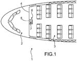
- the figure 1 schematically illustrates a front portion 1 of an aircraft fuselage comprising a cockpit access security lock.
- the front part 1 has a cockpit 2 separated from a passenger cabin 3 by a partition 4 provided with a cockpit door 5.
- This front part 1 is quite classic. It is not necessary to describe it in detail.
- the cockpit door 5 is pivotally mounted on said partition 4 and has a pivoting travel which can be cockpit side or passenger cabin side. It can be shielded, like the bulkhead, to withstand the impact of firearm projectiles.
- the security lock 6 provides communication between the cockpit 2 and the passenger cabin 3. It comprises, in addition to the cockpit door 5, separation means located on the side of the passenger cabin 3 with respect to said partition 4 and comprising at least a movable element.
- the security lock 6 thus defines a temporary transition zone 7 situated between the cockpit 2 and the passenger cabin 3.
- This transition zone 7 is delimited, on the one hand, with respect to the cockpit 2, by the cockpit door 5, and secondly vis-à-vis the passenger cabin 3, by the separation means when said movable member occupies said extended position of closure.
- FIGS. 2 and 3 illustrate, for information purposes only, a front part of an aircraft fuselage, and more particularly a safety airlock 6 comprising separation means 9.
- the contour 8 of the transition zone 7 of the security chamber 6 adjacent the passenger cabin 3 has a shape in an arc.
- the separation means 9 comprise two movable elements 10 each mounted sliding along an axis or a path parallel to the plane of the floor 11 on a frame structure.
- the frame structure may be the floor 11 of the airlock and the passenger cabin. It can also be a ceiling of airlock and passenger cabin (not shown).
- the movable elements 10 are slidable in guide rails 12 mounted on said structure.
- Each of the movable elements 10 is in the form of a panel 10 made in one piece, preferably shielded to withstand the impacts of projectiles firearms.
- the sliding path extends along said contour 8 of the transition zone 7 adjacent to the passenger cabin, and thus has a shape of an arc of a circle.
- each of said housings is, for example, a hollow box disposed near the cockpit partition 4 and which extends along a portion of the contour 8 of the transition zone 7 adjacent to the passenger cabin.
- the zone formed between the cockpit and the passenger cabin, and defined at least partially by the cockpit door on the one hand and by the sliding panels 10 when they occupy the retracted opening position, on the other hand has a surface strictly inferior to that of the transition zone 7.
- This surface is here negligible compared to the surface of the transition zone 7.
- the transition zone 7 is therefore a temporary zone in that its contour is defined when the sliding panels occupy the extended position of closure.
- the passenger cabin thus has a maximized space since the area of the zone intended to form the transition zone 7 is small or even negligible when the panels 10 are retracted.
- said sliding panels each comprise an end portion which remains housed inside the housing.
- said opening would indeed form a weak point of the security lock 6.
- the assembly comprising said housing caissons and said sliding panels occupy substantially all the contour 8 of the transition zone 7 adjacent to the passenger cabin 3.
- the passage of a person from the passenger cabin 3 at the transition zone 7 is made impossible.
- said housings are also shielded to withstand the impacts of projectiles from firearms.
- a request for access inside the cockpit 2 is then formulated via a device positioned inside the airlock 6.
- the sliding panels 10 then move from the retracted opening position to the extended closed position.
- the access request can then be validated to obtain the opening of the cockpit door 5.
- the cockpit door 5 is unlocked and the person present in the security chamber 6 can access the cockpit 2.
- the cockpit door 5 is then closed and locked.
- the sliding panels then move from the extended position of closure to the retracted position of opening.
- a cockpit door opening device 5 In the case where a person present in the cockpit 2 wishes to access the passenger cabin 3, it activates a cockpit door opening device 5. Before opening the cockpit door 5, the sliding panels 10 move from their retracted opening position to the extended closed position.
- the door of the cockpit 5 can thus be opened, without risk of intrusion of an unauthorized person from the passenger cabin 3 to the cockpit 2.
- the person enters the transition zone 7 of the security lock 6 and closes the cockpit door 5.
- the sliding panels then move from the extended position of closure to the retracted position of opening.
- the person can then access the passenger cabin 3.
- the security lock 6 may not be actuated.
- the transition from passenger cabin 3 to cockpit 2 and vice versa is simply by the cockpit door 5, said movable member 10 remaining in the retracted position of opening.
- the separation means 9 comprise only one sliding panel similar to one of those described above.
- the width of the sliding panel and that of the housing box are therefore adapted so that, when the sliding panel is in the extended closed position, it prevents, in cooperation with its housing housing, the passage of persons between the zone transitional 7 and passenger cabin 3.
- the sliding panel remains located at the contour 8 of the transition zone 7 adjacent to the passenger cabin 3.
- each of the sliding mobile elements is formed of a plurality of sliding panels where each panel is coupled to its neighbor panel (s) by a mechanical connection, for example pivot or slide. Each panel is thus coupled with its immediate neighbors, so that the displacement of one leads to the displacement of others.
- the panels are slidably mounted on said frame structure via the guide rails.
- Each panel then has a shape of an arc.
- the panels are arranged inside the housing caissons.
- the panels are then arranged so as to overlap each other.
- the panels are unfolded and extend along the contour of the transition zone adjacent to the passenger cabin.
- the sliding panels can remain localized at the contour defined between the transition zone and the passenger cabin.
- said movable member (s) may be formed of a grid, for example a metallic grid.
- the gate is shielded and has a mesh fine enough to stop the projectiles of firearms.
- said movable member (s) may be formed of a metal curtain, preferably with full blades and shielded.
- the movable element 10 of the separation means 9 may be formed of a single panel 10 made in one piece slidably mounted along an axis substantially orthogonal to the floor 11 of the lock.
- the floor 11 of the transition zone 7 separates an upper passenger transport zone from a lower cargo zone.
- the cargo area is disposed under the passenger zone along an axis orthogonal to the floor.
- Said floor 11 has an opening 13 which extends along the contour 8 of the transition zone 7 adjacent to the passenger cabin 3.
- Said panel 10 can then slide through said opening 13 so as to accommodate, in the retracted position of closure, in said lower cargo area.
- the size of the security lock 6 is then minimal insofar as said sliding panel 10, in the retracted opening position, is not present at the passenger cabin 3.
- This surface is here substantially zero or negligible.
- the passenger cabin has a maximized space since the area of the area intended to form the transition zone 7 is small or negligible when the panel 10 is retracted.
- the sliding panel 10 translates vertically upwards, that is to say from the cargo hold to the security lock 6. It is then located at the entire contour 8 of the transition zone 7 adjoining the passenger cabin 3.
- the sliding panel advantageously remains located at the level of said contour 8.
- the operation of the security lock 6 comprising a vertical sliding panel 10 is similar to that described above.
- the mobile element 10 of the separation means 9 is formed of a plurality of panels where each panel is coupled to its neighbor panel (s) so as to form a sliding flap.
- the sliding shutter can also be formed of an armored grid and having a sufficiently fine mesh to stop the projectiles of firearms.
- said flap may be formed of a metal curtain, preferably with full blades and shielded.
- the separation means 9 further comprise two lateral walls 14 extending from the cockpit partition 4 along part of the contour 8 of the transition zone 7 adjacent to the passenger cabin 3.
- the flap 10 is mounted rolling on a drum disposed in a casing 15 forming a housing.
- the housing housing 15 may be disposed at the floor of the lock chamber or at the ceiling thereof.
- the figure 5 illustrates this last embodiment.
- the flap 10 passes from the retracted position of opening to the extended position of closure by a vertical deployment upwards, that is to say from the floor of the airlock to the ceiling thereof.
- the flap 10 passes from the retracted position of opening to the extended position of closure by a downward sliding vertical deployment, that is to say, the ceiling of the lock at the floor thereof. More precisely, the shutter slides along guide rails mounted on the side walls 14.
- the rolling shutter 10 remains advantageously located at the contour 8 of the transition zone 7 adjacent to the passenger cabin 3.
- the operation of the security lock 6 according to this variant is similar to that described above with reference to the first example.
- the movable elements of the separation means may be formed of two roller shutters, the one and the other being housed, in the retracted position, in housing caissons arranged, respectively, at the ceiling of the airlock and at the floor of the airlock.
- transition zone 7 may have a half-disk shape, square, rectangular or other.
Description
La présente invention porte sur le domaine général de la sûreté à bord des aéronefs et concerne plus particulièrement une partie avant de fuselage d'aéronef comportant un cockpit communiquant avec une cabine passagers par l'intermédiaire d'un sas de sécurité.The present invention relates to the general field of safety on board aircraft and more particularly relates to an aircraft fuselage front part comprising a cockpit communicating with a passenger cabin via a safety lock.
A la suite des événements du 11 septembre 2001, il est apparu nécessaire d'améliorer la sûreté à bord des aéronefs, et notamment de sécuriser l'accès au cockpit.Following the events of 11 September 2001, it appeared necessary to improve the safety on board aircraft, including securing access to the cockpit.
Le cockpit était, avant ces événements, séparé de la cabine passagers par une simple cloison de séparation munie d'une porte non blindée de cockpit.The cockpit was, before these events, separated from the passenger cabin by a simple partition with an unshielded cockpit door.
Pour résister aux projectiles émis par des armes légères, la porte de cockpit, et éventuellement la cloison de séparation, ont été blindées.To resist the projectiles emitted by small arms, the cockpit door, and possibly the partition, were shielded.
Il reste toutefois important d'éviter l'intrusion dans le cockpit de toute personne non habilitée, notamment lors d'une ouverture momentanée de la porte de cockpit.However, it is important to avoid the intrusion into the cockpit of any unauthorized person, especially during a momentary opening of the cockpit door.
Il est en effet fréquent, au cours d'un vol, que des membres de l'équipage aient à sortir du cockpit ou à entrer dans celui-ci. La porte de cockpit est alors momentanément ouverte et une personne malveillante peut alors entrer de force dans le cockpit.It is indeed common, during a flight, that members of the crew have to leave the cockpit or enter it. The cockpit door is then momentarily open and an attacker can then force his way into the cockpit.
Il est possible de disposer un sas de sécurité entre le cockpit et la cabine passagers.It is possible to have a safety lock between the cockpit and the passenger cabin.
Le document
Cette solution présente cependant l'inconvénient de nécessiter un espace dédié important, par suite de l'encombrement des portes pivotantes, réduisant ainsi la zone utile de la cabine passagers. Par zone utile, on entend ici l'espace effectivement disponible pour le transport de passagers.However, this solution has the disadvantage of requiring a large dedicated space, due to the size of the pivoting doors, thus reducing the useful area of the passenger cabin. By useful area is meant here the space actually available for the transport of passengers.
En effet, l'espace dédié est formé de l'espace du couloir, ainsi que de l'espace nécessaire au débattement normal de la seconde porte. Dans le cas où la seconde porte s'ouvre à l'intérieur de la zone de transition, la longueur du couloir est alors fixée par la nécessité de permettre à ladite porte de pivoter normalement. Dans le cas contraire où la seconde porte pivote à l'extérieur de la zone de transition, donc dans la cabine passagers, la zone utile de la cabine passagers est diminuée de la zone de débattement de ladite porte. Dans les deux cas, ce sas de sécurité présente un encombrement important qui diminue la zone utile de la cabine passagers. Cela contrevient à l'exigence actuelle dans le domaine de l'aéronautique de maximiser la zone de cabine passagers dans le but de pouvoir transporter un plus grand nombre de passagers.Indeed, the dedicated space is formed of the corridor space, and the space required for the normal movement of the second door. In the case where the second door opens within the transition zone, the length of the corridor is then fixed by the need to allow said door to rotate normally. In the opposite case where the second door pivots outside the transition zone, so in the passenger cabin, the useful area of the passenger cabin is reduced by the range of movement of said door. In both cases, this airlock has a large footprint that reduces the useful area of the passenger cabin. This contravenes the current requirement in the aeronautics field to maximize the passenger cabin area in order to be able to carry more passengers.
Une autre solution est décrite dans le document
Cependant, cette solution présente également certains inconvénients en termes d'encombrement et de sécurité.However, this solution also has certain disadvantages in terms of size and safety.
Bien que le sas de sécurité à tambour selon ce second document ne présente pas de portes pivotantes, l'encombrement reste important du fait que la distance entre les deux ouvertures du bâti est imposée par la taille du tambour, et notamment son diamètre. Cette distance est alors de l'ordre du diamètre extérieur du tambour. La surface de la zone de transition est alors également imposée par la forme cylindrique du tambour et du bâti. Le sas de sécurité présente donc un encombrement important préjudiciable pour la zone utile de la cabine passagers.Although the safety lock drum according to this second document does not have pivoting doors, the size remains important because the distance between the two openings of the frame is imposed by the size of the drum, and in particular its diameter. This distance is then of the order of the outer diameter of the drum. The surface of the transition zone is then also imposed by the cylindrical shape of the drum and the frame. The security booth therefore presents a a significant amount of space that is detrimental to the useful area of the passenger cabin.
Par ailleurs, le sas selon ce document comporte nécessairement une structure additionnelle formant bâti présentant une forme de cylindre permettant d'une part de loger le tambour et d'autre part de coopérer avec celui-ci pour réaliser la fonction technique de sas de sécurité. La présence de cette structure entraîne un encombrement supplémentaire ainsi qu'un ajout de masse préjudiciable pour les performances de l'aéronef.Furthermore, the airlock according to this document necessarily comprises an additional structure forming a frame having a cylinder shape on the one hand to accommodate the drum and on the other hand to cooperate with it to perform the technical function of security lock. The presence of this structure leads to additional congestion as well as an addition of detrimental mass for the performance of the aircraft.
Enfin, le sas de sécurité selon ce document présente un défaut de sécurité. En effet, lorsqu'une personne souhaite accéder au cockpit, elle doit être présente dans la zone de transition du tambour pour en faire la demande. Lorsque la demande est validée, le tambour tourne pour venir mettre son ouverture en regard de l'ouverture du cockpit. Cependant, il existe un laps de temps pendant lequel, alors que la demande d'accès au cockpit est validée, l'ouverture du tambour est au moins en partie en regard de l'ouverture du bâti côté cabine passagers. Pendant ce laps de temps, le passage d'une personne non habilitée de la cabine passagers à la zone de transition du tambour reste possible, ce qui est particulièrement préjudiciable pour la sécurité du cockpit.Finally, the security lock according to this document has a security defect. Indeed, when a person wishes to access the cockpit, it must be present in the transition zone of the drum to make the request. When the request is validated, the drum rotates to put its opening opposite the opening of the cockpit. However, there is a period of time during which, while the request for access to the cockpit is validated, the opening of the drum is at least partly opposite the opening of the passenger cabin side frame. During this time, the passage of an unauthorized person from the passenger cabin to the transition zone of the drum remains possible, which is particularly detrimental to the safety of the cockpit.
Les documents
Ainsi, lorsque l'élément mobile est en position d'ouverture, les parois fixes continuent de matérialiser une partie du contour de la zone de transition, et continuent donc de délimiter partiellement la zone de transition.Thus, when the movable element is in the open position, the fixed walls continue to materialize part of the contour of the transition zone, and therefore continue to partially delimit the transition zone.
L'invention a principalement pour but de présenter une partie avant de fuselage d'aéronef comportant un accès sécurisé entre le cockpit et la cabine passagers, tout en présentant un encombrement réduit.The main purpose of the invention is to present an aircraft fuselage front part comprising a secure access between the cockpit and the passenger cabin, while having a small footprint.
Pour ce faire, l'invention a pour objet une partie avant de fuselage d'aéronef comportant un cockpit de pilotage, une cabine accessible aux passagers séparée dudit cockpit par une cloison munie d'une porte de cockpit, et des moyens de séparation situés du côté de la cabine passagers par rapport à ladite cloison et comprenant au moins un élément mobile.For this purpose, the subject of the invention is an aircraft fuselage front part comprising a pilot cockpit, a cabin accessible to passengers separated from the said cockpit by a partition provided with a cockpit door, and separation means situated from the cockpit, side of the passenger cabin relative to said partition and comprising at least one movable member.
Par cockpit, on entend ici la zone de l'aéronef correspondant au poste de pilotage. Le cockpit comporte notamment les sièges des pilotes ainsi que les moyens de commande de l'aéronef.Cockpit means here the area of the aircraft corresponding to the cockpit. The cockpit includes the seats of the pilots as well as the control means of the aircraft.
Par cabine passagers, on entend ici la zone de l'aéronef accessible aux passagers, et comportant notamment les sièges permettant d'accueillir les passagers pendant les phases de vol.Passenger cabin means here the area of the aircraft accessible to passengers, and including the seats to accommodate passengers during flight phases.
Selon l'invention, ledit élément mobile est apte à être déplacé par coulissement entre:
- une position déployée de fermeture dans laquelle lesdits moyens de séparation délimitent, avec ladite porte de cockpit, une zone de transition entre le cockpit et la cabine passagers, et empêchent tout passage de personnes entre la cabine passagers et ladite zone de transition ; et
- une position rétractée d'ouverture dans laquelle lesdits moyens de séparation permettent le passage de personnes entre la cabine passagers et ladite zone de transition.
- an extended closing position in which said separating means define, with said cockpit door, a transition zone between the cockpit and the passenger cabin, and prevent any passage of persons between the passenger cabin and said transition zone; and
- a retracted opening position in which said separation means allow the passage of persons between the passenger cabin and said transition zone.
De plus, ledit élément mobile s'étend, en position déployée de fermeture, suivant tout le contour de la zone de transition jouxtant la cabine passagers.In addition, said movable member extends, in the extended closed position, along the entire contour of the transition zone adjacent to the passenger cabin.
Ainsi, un sas de sécurité peut être formé entre le cockpit et la cabine passagers.Thus, a security lock can be formed between the cockpit and the passenger cabin.
Le sas comporte alors la porte de cockpit et les moyens de séparation. La zone de transition est une zone temporaire dans la mesure où son contour est défini lorsque l'élément mobile des moyens de séparation occupe la position déployée de fermeture.The airlock then comprises the cockpit door and the means of separation. The transition zone is a temporary zone to the extent that its contour is defined when the movable element of the separation means occupies the extended position of closure.
A la différence des exemples de l'art antérieur précédemment décrits, la distance minimale entre la porte de cockpit et les moyens de sécurité lorsque ledit élément mobile est en position déployée de fermeture n'est pas imposée par la structure ou les moyens du sas de sécurité.Unlike the examples of the prior art previously described, the minimum distance between the cockpit door and the safety means when said movable member is in the extended closed position is not imposed by the structure or the means of the lock chamber. security.
En effet, l'élément mobile des moyens de séparation est rétractable et déployable en coulissement. Il ne présente donc pas de zone de débattement inhérente à toute porte pivotante.Indeed, the movable member of the separation means is retractable and deployable in sliding. It does not present a range of movement inherent to any pivoting door.
De plus, la distance minimale entre ledit élément mobile et ladite porte de cockpit n'est pas non plus imposée par une éventuelle structure annulaire formant bâti telle que celle décrite dans le second exemple de l'art antérieur précédemment décrit.In addition, the minimum distance between said movable member and said cockpit door is also not imposed by a possible annular frame structure such as that described in the second example of the prior art described above.
Ainsi, à la différence des exemples de l'art antérieur mentionnés précédemment, la distance entre la porte de cockpit et l'élément mobile en position déployée de fermeture peut donc être optimisée et diminuée au strict nécessaire, par exemple à la distance nécessaire permettant à une personne de se tenir dans la zone de transition ainsi définie. La surface de la zone de transition est alors minimisée, ce qui procure un encombrement particulièrement réduit du sas de sécurité et permet d'obtenir en conséquence une importante zone utile de la cabine passagers.Thus, unlike the examples of the prior art mentioned above, the distance between the cockpit door and the movable element in the extended closed position can therefore be optimized and reduced to the necessary minimum, for example to the necessary distance allowing a person to stand in the transition zone so defined. The surface of the transition zone is then minimized, which provides a particularly small footprint of the security chamber and allows to obtain accordingly a large useful area of the passenger cabin.
Par ailleurs, le sas de sécurité ne présente pas de structure additionnelle formant bâti et présentant une ouverture de cockpit et une ouverture de cabine passagers. L'invention permet ainsi de réaliser un gain de masse particulièrement avantageux pour les performances de l'aéronef. L'intégration du sas de sécurité dans la structure globale des parties avant classiques d'aéronef peut également être réalisée simplement, sans compliquer les chaînes d'assemblage et les procédures de fabrication.In addition, the security chamber has no additional structure forming a frame and having a cockpit opening and a passenger cabin opening. The invention thus makes it possible to achieve a particularly advantageous mass gain for the aircraft's performance. The integration of the security lock into the overall structure of conventional aircraft front parts can also be achieved simply, without complicating the assembly lines and manufacturing procedures.
Enfin, le sas de sécurité présente un niveau de sécurité élevé dans la mesure où l'actionnement des moyens de sécurité est indépendant de celui de la porte de cockpit. A la différence du second exemple de l'art antérieur, le sas de sécurité selon l'invention ne présente pas de laps de temps pendant lequel une personne non habilitée pourrait s'introduire indûment à l'intérieur du sas, alors que l'élément mobile serait en cours de mouvement de fermeture. En effet, lorsqu'une personne est présente dans le sas et fait une demande d'accès au cockpit, l'élément mobile vient occuper, avant toute validation de la demande, la position déployée de fermeture. Ainsi, la sécurité du cockpit est assurée à tout instant.Finally, the security chamber has a high level of security insofar as the actuation of the security means is independent of that of the cockpit door. Unlike the second example of the prior art, the safety lock according to the invention There is no period of time during which an unauthorized person could improperly enter the airlock while the moving element is in the process of being closed. Indeed, when a person is present in the airlock and makes a request for access to the cockpit, the movable member occupies, before any validation of the request, the deployed position of closure. Thus, the security of the cockpit is assured at all times.
La zone de transition comporte un plancher. De préférence, le plancher est commun avec celui de la cabine passagers, et avec celui du cockpit.The transition zone has a floor. Preferably, the floor is common with that of the passenger cabin, and with that of the cockpit.
Selon un premier mode de réalisation, ledit élément mobile est coulissant suivant un axe parallèle audit plancher.According to a first embodiment, said movable element is sliding along an axis parallel to said floor.
Selon un second mode de réalisation, ledit élément mobile est coulissant suivant un axe orthogonal audit plancher.According to a second embodiment, said movable element is sliding along an axis orthogonal to said floor.
Avantageusement, ledit élément mobile reste intégralement localisé, lors de son déplacement entre l'une et l'autre desdites positions, suivant le contour de la zone de transition jouxtant la cabine passagers.Advantageously, said movable element remains fully localized, during its movement between one and the other of said positions, along the contour of the transition zone adjacent to the passenger cabin.
Par contour de la zone de transition jouxtant la cabine passagers, on entend la ligne suivant laquelle s'étendent les moyens de séparation lorsque ledit élément mobile occupe la position déployée de fermeture. La surface de la zone de transition est définie par la surface délimitée par la porte de cockpit d'une part et les moyens de séparation lorsque ledit élément mobile occupe la position déployée de fermeture d'autre part, et obtenue suivant une section parallèle au plan du plancher du sas de sécurité. Le plan du plancher du sas de sécurité est défini comme étant un plan orthogonal au plan de symétrie de l'aéronef.By contour of the transition zone adjacent to the passenger cabin is meant the line along which the separation means extend when said movable member occupies the extended position of closure. The surface of the transition zone is defined by the surface defined by the cockpit door on the one hand and the separation means when said movable element occupies the deployed position of closing on the other hand, and obtained in a section parallel to the plane of the floor of the security chamber. The floor plan of the security chamber is defined as a plane orthogonal to the plane of symmetry of the aircraft.
Avantageusement, lesdits moyens de séparation, lorsque ledit élément mobile occupe ladite position rétractée d'ouverture, délimitent avec ladite porte du cockpit au moins partiellement une zone présentant une surface strictement inférieure à celle de la zone de transition.Advantageously, said separating means, when said movable element occupies said retracted opening position, delimit with said cockpit door at least partially an area having a surface strictly smaller than that of the transition zone.
La surface de ladite zone définie lorsque ledit élément mobile occupe la position rétractée d'ouverture peut être sensiblement nulle ou négligeable.The area of said defined area when said movable member is in the retracted opening position may be substantially zero or negligible.
La zone de transition est donc bien une zone temporaire dans la mesure où son contour est défini lorsque l'élément mobile occupe la position déployée de fermeture.The transition zone is therefore a temporary zone to the extent that its contour is defined when the movable element occupies the extended position of closure.
La cabine passagers présente ainsi un espace maximisé puisque la surface de la zone destinée à former la zone de transition est faible voire négligeable lorsque l'élément mobile est rétracté.The passenger cabin thus has a maximized space since the area of the zone intended to form the transition zone is small or even negligible when the mobile element is retracted.
Ledit élément mobile peut être formé d'un panneau réalisé d'un seul tenant, d'une pluralité de panneaux où chacun desdits panneaux est couplé à au moins un panneau voisin, voire d'une grille ou d'un rideau.Said movable element may be formed of a panel made in one piece, a plurality of panels where each of said panels is coupled to at least one adjacent panel, or even a grid or a curtain.
Par panneau, on entend une plaque ou une planche de forme générale sensiblement rectangulaire. Par panneau voisin, on entend un panneau adjacent au panneau considéré. Par panneaux couplés l'un à l'autre, on entend des panneaux reliés l'un à l'autre par une liaison mécanique. Ainsi, chaque panneau de ladite pluralité de panneaux peut être relié au(x) panneau(x) voisin(s) par tout type de liaison mécanique, par exemple une liaison pivot ou glissière. Par ailleurs, la pluralité de panneaux comprend au moins deux panneaux.By panel is meant a plate or board of generally rectangular shape. By adjacent panel is meant a panel adjacent to the panel considered. By panels coupled to each other is meant panels connected to one another by a mechanical connection. Thus, each panel of said plurality of panels may be connected to the adjacent panel (s) by any type of mechanical connection, for example a pivot or slide connection. In addition, the plurality of panels comprises at least two panels.
Par grille, on entend un treillis de barreaux en matériau métallique ou en matériau plastique de haute résistance, les barreaux étant reliés deux à deux par une liaison mécanique de type, par exemple, pivot.Grid means a mesh of bars made of metallic material or of high-strength plastic material, the bars being connected in pairs by a mechanical connection of the type, for example pivot.
Selon une possibilité de réalisation, le plancher de la zone de transition sépare une zone supérieure de transport de passagers d'une zone inférieure dite cargo. La zone cargo est disposée sous la cabine passagers suivant un axe orthogonal au plancher. Ledit plancher comporte une ouverture qui s'étend suivant le contour de la zone de transition jouxtant la cabine passagers. Ledit élément mobile est alors apte à coulisser au travers de ladite ouverture de manière à loger, en position rétractée de fermeture, dans ladite zone inférieure cargo. L'encombrement du sas de sécurité est alors minimal dans la mesure où ledit élément mobile, en position rétractée d'ouverture, n'est pas présent au niveau de la cabine passagers.According to one embodiment, the floor of the transition zone separates an upper passenger transport zone from a lower cargo zone. The cargo area is arranged under the passenger cabin along an axis orthogonal to the floor. Said floor has an opening that extends along the contour of the transition zone adjacent to the passenger cabin. Said movable element is then able to slide through said opening so as to house, in retracted position of closure, in said lower cargo area. The size of the security chamber is then minimal insofar as said movable element, in the retracted position of opening, is not present at the passenger cabin.
Avantageusement, pour améliorer la sécurisation de l'accès au cockpit, lesdits moyens de séparation sont blindés. La porte de cockpit et la cloison entre le cockpit et la cabine passagers peuvent également être blindés. Le blindage permet notamment de résister aux impacts de projectiles d'armes à feu.Advantageously, to improve the security of access to the cockpit, said separation means are shielded. The cockpit door and the bulkhead between the cockpit and the passenger cabin can also be shielded. The armor makes it possible to withstand the impact of firearm projectiles.
L'invention porte également sur un aéronef comportant une partie avant de fuselage selon l'une quelconque des caractéristiques décrites précédemment.The invention also relates to an aircraft comprising a fuselage front part according to any one of the features described above.
D'autres avantages et caractéristiques de l'invention apparaîtront dans la description détaillée non limitative ci-dessous.Other advantages and features of the invention will become apparent in the detailed non-limiting description below.
On décrira à présent, à titre d'exemples non limitatifs, des modes de réalisation de l'invention, en se référant aux dessins annexés, dans lesquels:
- La
figure 1 est une vue schématique en coupe d'une partie avant de fuselage d'aéronef comportant un sas de sécurité entre la cabine passagers et le cockpit; - La
figure 2 est une vue schématique en coupe d'une partie avant de fuselage d'aéronef comportant un sas de sécurité décrit à titre d'information ; - La
figure 3 est une vue schématique en perspective du sas de sécurité représenté sur lafigure 2 ; - La
figure 4 est une vue schématique en perspective d'un sas de sécurité selon un mode de réalisation de l'invention ; - La
figure 5 est une vue schématique en perspective d'un sas de sécurité décrit à titre d'information.
- The
figure 1 is a schematic cross-sectional view of an aircraft fuselage front part including a safety airlock between the passenger cabin and the cockpit; - The
figure 2 is a schematic cross-sectional view of an aircraft fuselage nose section with a security airlock described for information purposes; - The
figure 3 is a schematic perspective view of the security lock represented on thefigure 2 ; - The
figure 4 is a schematic perspective view of a security lock according to one embodiment of the invention; - The
figure 5 is a schematic perspective view of a security lock described for information purposes.
La
La porte de cockpit 5 est montée pivotante sur ladite cloison 4 et présente un débattement de pivotement qui peut être côté cockpit ou côté cabine passagers. Elle peut être blindée, tout comme la cloison, pour résister aux impacts de projectiles d'armes à feu.The
Le sas de sécurité 6 assure la communication entre le cockpit 2 et la cabine passagers 3. Il comporte, outre la porte de cockpit 5, des moyens de séparation situés du côté de la cabine passagers 3 par rapport à ladite cloison 4 et comprenant au moins un élément mobile.The
Ledit élément mobile est apte à être déplacé par coulissement entre:
- une position déployée de fermeture dans laquelle lesdits moyens de séparation délimitent, avec ladite porte de cockpit, une
zone de transition 7 entre lecockpit 2 et la cabine passagers 3, et empêchent tout passage de personnes entre la cabine passagers 2 et laditezone de transition 7 ; et - une position rétractée d'ouverture dans laquelle lesdits moyens de séparation permettent le passage de personnes entre la cabine passagers 3 et ladite
zone de transition 7.
- an extended position of closure in which said separation means delimit, with said cockpit door, a
transition zone 7 between thecockpit 2 and thepassenger cabin 3, and prevent any passage of persons between thepassenger cabin 2 and saidtransition zone 7; and - a retracted position of opening in which said separation means allow the passage of persons between the
passenger cabin 3 and saidtransition zone 7.
Le sas de sécurité 6 définit ainsi une zone de transition 7 temporaire située entre le cockpit 2 et la cabine passagers 3. Cette zone de transition 7 est délimitée, d'une part vis-à-vis du cockpit 2, par la porte de cockpit 5, et d'autre part vis-à-vis de la cabine passagers 3, par les moyens de séparation lorsque ledit élément mobile occupe ladite position déployée de fermeture.The
Les
Le contour 8 de la zone de transition 7 du sas de sécurité 6 jouxtant la cabine passagers 3 présente une forme en arc de cercle.The
Les moyens de séparation 9 comportent deux éléments mobiles 10 montés chacun coulissants suivant un axe ou un chemin parallèle au plan du plancher 11 sur une structure formant bâti. La structure formant bâti peut être le plancher 11 du sas et de la cabine passagers. Elle peut également être un plafond de sas et de cabine passagers (non représenté). Les éléments mobiles 10 sont coulissants dans des rails 12 de guidage montés sur ladite structure.The separation means 9 comprise two
Chacun des éléments mobiles 10 se présente sous la forme d'un panneau 10 réalisé d'un seul tenant, de préférence blindé pour résister aux impacts des projectiles d'armes à feu.Each of the
Le chemin de coulissement s'étend suivant ledit contour 8 de la zone de transition 7 jouxtant la cabine passagers, et présente donc une forme d'arc de cercle.The sliding path extends along said
Lorsque les panneaux 10 coulissants occupent la position rétractée d'ouverture, ils sont rabattus à proximité de la cloison de cockpit 4.When the sliding
Dans cette position, les panneaux 10 coulissants sont logés chacun à l'intérieur d'un logement. Chacun desdits logements est, par exemple, un caisson creux disposé à proximité de la cloison de cockpit 4 et qui s'étend suivant une partie du contour 8 de la zone de transition 7 jouxtant la cabine passagers.In this position, the sliding panels are housed each inside a housing. Each of said housings is, for example, a hollow box disposed near the
Ainsi, la zone formée entre le cockpit et la cabine passagers, et délimitée au moins partiellement par la porte de cockpit d'une part et par les panneaux 10 coulissants lorsqu'ils occupent la position rétractée d'ouverture d'autre part présente une surface strictement inférieure par rapport à celle de la zone de transition 7.Thus, the zone formed between the cockpit and the passenger cabin, and defined at least partially by the cockpit door on the one hand and by the sliding
Cette surface est ici négligeable par rapport à la surface de la zone de transition 7.This surface is here negligible compared to the surface of the
La zone de transition 7 est donc bien une zone temporaire dans la mesure où son contour est défini lorsque les panneaux 10 coulissants occupent la position déployée de fermeture.The
La cabine passagers présente ainsi un espace maximisé puisque la surface de la zone destinée à former la zone de transition 7 est faible voire négligeable lorsque les panneaux 10 sont rétractés.The passenger cabin thus has a maximized space since the area of the zone intended to form the
Lorsque les panneaux 10 coulissants occupent ladite position déployée de fermeture, ils sont situés essentiellement à l'extérieur de leur logement respectif, éloignés de la cloison de cockpit 4.When the sliding panels occupy said extended closed position, they are located essentially outside their respective housing, away from the
Cependant, pour une meilleure sécurité, lesdits panneaux 10 coulissants comportent chacun une partie d'extrémité qui reste logée à l'intérieur du logement. Ainsi, il n'y a pas d'ouverture entre chacun des panneaux 10 coulissants et le logement associé. Cette ouverture formerait en effet un point faible du sas de sécurité 6.However, for better security, said sliding panels each comprise an end portion which remains housed inside the housing. Thus, there is no opening between each of the sliding panels and the associated housing. This opening would indeed form a weak point of the
Dans cette position déployée de fermeture, l'ensemble comprenant lesdits caissons formant logement et lesdits panneaux 10 coulissants occupent sensiblement tout le contour 8 de la zone de transition 7 jouxtant la cabine passagers 3. Ainsi, le passage d'une personne de la cabine passagers 3 à la zone de transition 7 est rendu impossible.In this extended closing position, the assembly comprising said housing caissons and said sliding panels occupy substantially all the
De préférence, lesdits logements sont également blindés pour résister aux impacts des projectiles des armes à feu.Preferably, said housings are also shielded to withstand the impacts of projectiles from firearms.
Le fonctionnement du sas de sécurité 6 décrit ci-dessus à titre informatif est maintenant décrit.The operation of the
Lorsque la porte de cockpit 5 est en position fermée, les panneaux 10 coulissants occupent la position rétractée d'ouverture.When the
Il est alors possible d'accéder, à partir de la cabine passagers 3, à la zone de transition 7 du sas de sécurité 6.It is then possible to access, from the
Ainsi, lorsqu'une personne souhaite accéder au cockpit, elle entre à l'intérieur du sas de sécurité 6 en passant de la cabine passagers 3 à la zone de transition 7.Thus, when a person wishes to access the cockpit, it enters the
Une demande d'accès à l'intérieur du cockpit 2 est alors formulée via un dispositif positionné à l'intérieur du sas 6.A request for access inside the
Les panneaux 10 coulissants passent alors de la position rétractée d'ouverture à la position déployée de fermeture.The sliding
Lors de ce changement de position, les panneaux 10 coulissent intégralement le long du contour 8 de la zone de transition 7 jouxtant la cabine passagers 3.During this change of position, the
Les panneaux 10 coulissants, en position déployée de fermeture, empêchent alors toute entrée d'une personne supplémentaire à l'intérieur du sas de sécurité 6.The sliding panels, in the extended position of closure, then prevent any entry of an additional person inside the
La demande d'accès peut ensuite être validée pour obtenir l'ouverture de la porte de cockpit 5.The access request can then be validated to obtain the opening of the
Elle peut être validée de manière automatique par la présentation d'une carte d'accès propre aux personnes habilitées. Elle peut également être validée par l'équipage présent à l'intérieur du cockpit 2, au moyen d'un dispositif de visualisation de type caméra ou fenêtre située dans la porte de cockpit 5.It can be validated automatically by presenting an access card specific to authorized persons. It can also be validated by the crew present inside the
Lorsque la demande est validée, la porte de cockpit 5 est déverrouillée et la personne présente dans le sas de sécurité 6 peut accéder au cockpit 2.When the request is validated, the
La porte de cockpit 5 est ensuite refermée et verrouillée. Les panneaux 10 coulissants passent alors de la position déployée de fermeture à la position rétractée d'ouverture.The
La procédure de passage d'une personne de la cabine passagers 3 au cockpit 2 peut alors être renouvelée.The procedure of passage of a person from the
Dans le cas où une personne présente dans le cockpit 2 souhaite accéder à la cabine passagers 3, elle active un dispositif d'ouverture de porte de cockpit 5. Avant l'ouverture de la porte du cockpit 5, les panneaux 10 coulissants passent de leur position rétractée d'ouverture à la position déployée de fermeture.In the case where a person present in the
La porte du cockpit 5 peut ainsi être ouverte, sans risque d'intrusion d'une personne non habilitée de la cabine passagers 3 au cockpit 2.The door of the
La personne entre dans la zone de transition 7 du sas de sécurité 6 et ferme la porte du cockpit 5.The person enters the
Les panneaux 10 coulissants passent alors de la position déployée de fermeture à la position rétractée d'ouverture.The sliding panels then move from the extended position of closure to the retracted position of opening.
La personne peut ensuite accéder à la cabine passagers 3.The person can then access the
La procédure de passage d'une personne de la cabine passagers 3 au cockpit 2, ou inversement, peut alors être renouvelée.The procedure of passing a person from the
Ainsi, il apparaît qu'à aucun moment de la procédure de passage d'une personne entre la cabine passagers 3 et le cockpit 2, une personne non habilitée peut s'introduire à l'intérieur du cockpit 2 à partir de la cabine passagers 3.Thus, it appears that at no time in the procedure of passage of a person between the
Par ailleurs, dans le cas d'une panne d'alimentation des panneaux 10 coulissants, celles-ci peuvent être actionnées manuellement, sans porter atteinte aux opérations de pilotage ou de service des passagers effectuées durant le vol.Furthermore, in the event of a power failure of the sliding
Enfin, dans le cas où l'aéronef est dépourvu de passagers et qu'il n'y a aucun risque d'intrusion dans le cockpit d'une personne malveillante, le sas de sécurité 6 peut ne pas être actionné. Le passage de la cabine passagers 3 au cockpit 2 et inversement se fait simplement par la porte du cockpit 5, ledit élément mobile 10 restant en position rétractée d'ouverture.Finally, in the case where the aircraft is devoid of passengers and there is no risk of intrusion into the cockpit of a malicious person, the
En variante, les moyens de séparation 9 ne comportent qu'un seul panneau 10 coulissant similaire à l'un de ceux décrits précédemment. La largeur du panneau 10 coulissant et celle du caisson formant logement sont donc adaptées, de sorte que, lorsque le panneau 10 coulissant est en position déployée de fermeture, il empêche, en coopération avec son caisson formant logement, le passage de personnes entre la zone de transition 7 et la cabine passagers 3.In a variant, the separation means 9 comprise only one sliding panel similar to one of those described above. The width of the sliding panel and that of the housing box are therefore adapted so that, when the sliding panel is in the extended closed position, it prevents, in cooperation with its housing housing, the passage of persons between the zone transitional 7 and
Lors du passage de la position rétractée à la position déployée, et inversement, le panneau 10 coulissant reste localisé au niveau du contour 8 de la zone de transition 7 jouxtant la cabine passagers 3.During the transition from the retracted position to the deployed position, and vice versa, the sliding panel remains located at the
Le fonctionnement du sas de sécurité 6 comportant un seul panneau 10 coulissant selon cette variante est similaire à celui décrit ci-dessus.The operation of the
Une deuxième variante (non représentée) est maintenant décrite.A second variant (not shown) is now described.
Selon cette variante, chacun des éléments mobiles coulissants est formé d'une pluralité de panneaux coulissants où chaque panneau est couplé à son ou ses panneau(x) voisin(s) par une liaison mécanique, par exemple pivot ou glissière. Chaque panneau est ainsi couplé à ses voisins immédiats, de sorte que le déplacement de l'un entraîne le déplacement des autres.According to this variant, each of the sliding mobile elements is formed of a plurality of sliding panels where each panel is coupled to its neighbor panel (s) by a mechanical connection, for example pivot or slide. Each panel is thus coupled with its immediate neighbors, so that the displacement of one leads to the displacement of others.
Les panneaux sont montés coulissants sur ladite structure formant bâti par l'intermédiaire des rails de guidage.The panels are slidably mounted on said frame structure via the guide rails.
Chaque panneau présente alors une forme d'arc de cercle.Each panel then has a shape of an arc.
Lorsque les éléments coulissants occupent la position rétractée d'ouverture, les panneaux sont disposés à l'intérieur des caissons formant logement.When the sliding elements occupy the retracted position of opening, the panels are arranged inside the housing caissons.
Pour limiter l'encombrement suivant le contour de la zone de transition jouxtant la cabine passagers, les panneaux sont alors disposés de manière à se chevaucher mutuellement.To limit the size following the outline of the transition zone adjacent to the passenger cabin, the panels are then arranged so as to overlap each other.
Lorsque les éléments coulissants occupent la position déployée de fermeture, les panneaux sont dépliés et s'étendent le long du contour de la zone de transition jouxtant la cabine passagers.When the sliding elements occupy the extended closed position, the panels are unfolded and extend along the contour of the transition zone adjacent to the passenger cabin.
Comme pour les différents exemples décrits précédemment, lors du passage de la position rétractée à la position déployée, et inversement, les panneaux coulissants peuvent rester localisés au niveau du contour défini entre la zone de transition et la cabine passagers.As for the various examples described above, during the transition from the retracted position to the deployed position, and vice versa, the sliding panels can remain localized at the contour defined between the transition zone and the passenger cabin.
Le fonctionnement du sas de sécurité comportant des éléments coulissants selon cette variante est similaire à celui décrit précédemment.The operation of the security lock with sliding elements according to this variant is similar to that described above.
Bien entendu, dans le cadre des exemples décrits ci-dessus et de l'invention décrite ci-dessous, il est possible de ne prévoir qu'un seul élément mobile formé d'une pluralité de panneaux où chaque panneau est couplé à son ou ses panneau(x) voisin(s). Par ailleurs, et selon une autre variante, ledit ou les élément(s) mobile(s) peut(peuvent) être formé(s) d'une grille, par exemple métallique. Par mesure de sécurité, la grille est blindée et présente un maillage suffisamment fin pour stopper les projectiles d'armes à feu. Alternativement, ledit ou les élément(s) mobile(s) peut(peuvent) être formé(s) d'un rideau métallique, de préférence à lames pleines et blindés.Of course, in the context of the examples described above and of the invention described below, it is possible to provide only one mobile element formed of a plurality of panels where each panel is coupled to its or its neighboring sign (s). Otherwise, and according to another variant, said movable member (s) may be formed of a grid, for example a metallic grid. As a safety measure, the gate is shielded and has a mesh fine enough to stop the projectiles of firearms. Alternatively, said movable member (s) may be formed of a metal curtain, preferably with full blades and shielded.
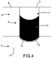
Selon un mode de réalisation de l'invention illustré sur la
Le plancher 11 de la zone de transition 7 sépare une zone supérieure de transport de passagers d'une zone inférieure dite cargo. La zone cargo est disposée sous la zone passagers suivant un axe orthogonal au plancher.The
Ledit plancher 11 comporte une ouverture 13 qui s'étend suivant le contour 8 de la zone de transition 7 jouxtant la cabine passagers 3.Said
Ledit panneau 10 peut alors coulisser au travers de ladite ouverture 13 de manière à loger, en position rétractée de fermeture, dans ladite zone inférieure cargo. L'encombrement du sas de sécurité 6 est alors minimal dans la mesure où ledit panneau 10 coulissant, en position rétractée d'ouverture, n'est pas présent au niveau de la cabine passagers 3.Said
Ainsi, la zone formée entre le cockpit et la cabine passagers, et délimitée au moins partiellement par la porte de cockpit d'une part et par le panneau 10 coulissant lorsqu'il occupe la position rétractée d'ouverture d'autre part, présente une surface strictement inférieure par rapport à celle de la zone de transition 7.Thus, the zone formed between the cockpit and the passenger cabin, and at least partially delimited by the cockpit door on the one hand and by the sliding panel when it occupies the retracted opening position, on the other hand, presents a a strictly lower surface than that of the
Cette surface est ici sensiblement nulle ou négligeable.This surface is here substantially zero or negligible.
La cabine passagers présente bien un espace maximisé puisque la surface de la zone destinée à former la zone de transition 7 est faible voire négligeable lorsque le panneau 10 est rétracté.The passenger cabin has a maximized space since the area of the area intended to form the
Pour passer en position déployée de fermeture, le panneau 10 coulissant effectue une translation verticale vers le haut, c'est-à-dire de la soute cargo au sas de sécurité 6. Il est ensuite situé au niveau de tout le contour 8 de la zone de transition 7 jouxtant la cabine passagers 3.To move to the extended closed position, the sliding
Comme pour les différents exemples précédemment décrits, lors du passage de la position rétractée à la position déployée, le panneau 10 coulissant reste avantageusement localisé au niveau dudit contour 8.As for the various examples described above, during the transition from the retracted position to the deployed position, the sliding panel advantageously remains located at the level of said
Le fonctionnement du sas de sécurité 6 comportant un panneau 10 à coulissement vertical est similaire à celui décrit précédemment.The operation of the
Dans des variantes de réalisation de l'invention et dans un autre exemple décrit à titre informatif et représenté sur la
Dans l'exemple décrit à titre informatif et représenté sur la
Le volet 10 est monté roulant sur un tambour disposé dans un caisson 15 formant logement.The
Le caisson 15 formant logement peut être disposé au niveau du plancher du sas ou au niveau du plafond de celui-ci. La
Dans le premier cas, le volet 10 passe de la position rétractée d'ouverture à la position déployée de fermeture par un déploiement vertical vers le haut, c'est-à-dire du plancher du sas au plafond de celui-ci.In the first case, the
Dans le second cas (illustré sur la
Comme pour les différents exemples décrits précédemment, lors du passage de la position rétractée à la position déployée, et inversement, le volet 10 roulant et coulissant reste avantageusement localisé au niveau du contour 8 de la zone de transition 7 jouxtant la cabine passagers 3.As for the various examples described above, during the transition from the retracted position to the deployed position, and vice versa, the rolling
Le fonctionnement du sas de sécurité 6 selon cette variante est similaire à celui décrit précédemment en référence au premier exemple.The operation of the
Par ailleurs, il est également possible que les éléments mobiles des moyens de séparation soient formés de deux volets roulants, l'un et l'autre étant logés, en position rétractée, dans des caissons formant logement disposés, respectivement, au niveau du plafond du sas et au niveau du plancher du sas.Furthermore, it is also possible for the movable elements of the separation means to be formed of two roller shutters, the one and the other being housed, in the retracted position, in housing caissons arranged, respectively, at the ceiling of the airlock and at the floor of the airlock.
Bien entendu, diverses modifications peuvent être apportées par l'homme du métier à l'invention qui vient d'être décrite, uniquement à titre d'exemples non limitatifs.Of course, various modifications may be made by those skilled in the art to the invention which has just been described, solely by way of non-limiting examples.
Par ailleurs, la zone de transition 7 peut présenter une forme de demi-disque, carrée, rectangulaire ou autre.Moreover, the
Claims (9)
- An aircraft fuselage nose section (1) including a cockpit (2), a cabin (3) accessible to passengers which is separated from said cockpit (2) by a partition wall (4) provided with a cockpit door (5), and separating means (9) located on the passenger cabin (3) side with respect to said partition wall (4) and comprising at least one movable element (10), said movable element (10) being slidingly movable between:- an extended closing position wherein said separating means (9) bound, with said cockpit door (5), a transition zone (7) between the cockpit (2) and the passenger cabin (3), and prevent people from passing between the passenger cabin (3) and said transition zone (7); and- a retracted opening position wherein said separating means (9) allow people to pass between the passenger cabin (3) and said transition zone (7);characterised in that said movable element (10) extends, in the extended closing position, along the entire perimeter (8) of the transition zone (7) adjoining the passenger cabin (3).
- The aircraft fuselage nose section (1) according to claim 1, characterised in that, when said movable element (10) assumes said retracted opening position, said separation means (9) bound with said cockpit door (5) at least partly a zone having an area strictly lower than that of the transition zone (7).
- The aircraft fuselage nose section (1) according to claim 1 or 2, characterised in that the transition zone (7) includes a floor (11), said movable element (10) being slidable along an axis parallel or orthogonal to said floor (11).
- The aircraft fuselage nose section (1) according to any of claims 1 to 3, characterised in that said movable element (10) remains fully located, during its displacement between both said positions, along the perimeter (8) of the transition zone (7) adjoining the passenger cabin (3).
- The aircraft fuselage nose section (1) according to any of claims 1 to 4, characterised in that said movable element (10) is formed by a panel made as a single piece.
- The aircraft fuselage nose section (1) according to any of claims 1 to 4, characterised in that said movable element (10) is formed by a plurality of panels, each of said panels being coupled to at least one contiguous panel.
- The aircraft fuselage nose section (1) according to any of claims 1 to 4, characterised in that said movable element (10) is formed by a grid or curtain.
- The aircraft fuselage nose section (1) according to any of claims 1 to 7, characterised in that said transition zone (7) includes a floor (11), said floor (11) separating a passenger transport upper zone from a so-called cargo lower zone, and including an opening (13) which extends along the perimeter (8) of the transition zone (7) adjoining the passenger cabin (3), and in that said movable element (10) is slidable through said opening (13) so as to be accommodated, in the closing retracted position, in said cargo lower zone.
- An aircraft, characterised in that it includes a fuselage nose section (1) according to any of the preceding claims.
Applications Claiming Priority (2)
| Application Number | Priority Date | Filing Date | Title |
|---|---|---|---|
| FR0957881A FR2952347B1 (en) | 2009-11-06 | 2009-11-06 | FRONT PART OF AN AIRCRAFT HAVING A COCKPIT ACCES SAS |
| PCT/FR2010/052389 WO2011055097A2 (en) | 2009-11-06 | 2010-11-05 | Front portion of an aircraft, comprising a vestibule for accessing the cockpit |
Publications (2)
| Publication Number | Publication Date |
|---|---|
| EP2496476A2 EP2496476A2 (en) | 2012-09-12 |
| EP2496476B1 true EP2496476B1 (en) | 2017-01-04 |
Family
ID=42184041
Family Applications (1)
| Application Number | Title | Priority Date | Filing Date |
|---|---|---|---|
| EP10795423.2A Active EP2496476B1 (en) | 2009-11-06 | 2010-11-05 | Aircraft cabin comprising a flight deck security system |
Country Status (6)
| Country | Link |
|---|---|
| US (1) | US8925863B2 (en) |
| EP (1) | EP2496476B1 (en) |
| CN (1) | CN102648129B (en) |
| CA (1) | CA2779529C (en) |
| FR (1) | FR2952347B1 (en) |
| WO (1) | WO2011055097A2 (en) |
Families Citing this family (7)
| Publication number | Priority date | Publication date | Assignee | Title |
|---|---|---|---|---|
| FR2965793B1 (en) * | 2010-10-08 | 2013-06-14 | Airbus Operations Sas | SAS SECURE ACCESS TO COCKPIT OF AN AIRCRAFT AND AIRCRAFT EQUIPPED WITH SUCH A SAS ACCESS |
| FR3036097B1 (en) | 2015-05-12 | 2017-04-28 | Airbus Operations Sas | ACCESS DEVICE WITH INDEPENDENT MOBILE WALLS FOR SECURE COMMUNICATION BETWEEN AT LEAST TWO ZONES OF AN ENCLOSURE |
| FR3036098B1 (en) * | 2015-05-12 | 2017-05-12 | Airbus Operations Sas | FOLDING WALL ACCESS DEVICE FOR SECURE COMMUNICATION BETWEEN AT LEAST TWO ZONES OF AN ENCLOSURE |
| US10112719B2 (en) * | 2016-03-18 | 2018-10-30 | The Boeing Company | Deployable clearance panel system, method, and assembly for a monument within an internal cabin of an aircraft |
| US11279461B2 (en) * | 2017-06-01 | 2022-03-22 | The Boeing Company | Flight deck barrier door, aircraft comprising flight deck barrier door, and method of using flight deck barrier door |
| US20200198785A1 (en) | 2018-12-21 | 2020-06-25 | Airbus Operations Gmbh | Aircraft barrier system having a delaying unlocking mechanism, and aircraft area and aircraft having such aircraft barrier system |
| DE102019117055B4 (en) * | 2019-06-25 | 2023-04-20 | Schroth Safety Products Gmbh | Device for preventing access to an area of an aircraft |
Family Cites Families (16)
| Publication number | Priority date | Publication date | Assignee | Title |
|---|---|---|---|---|
| US3480989A (en) * | 1968-02-05 | 1969-12-02 | Nat Mfg Co | Pocket door assembly |
| US3704845A (en) * | 1971-01-14 | 1972-12-05 | Michael Ord | Airplane hijacking prevention system |
| US3811643A (en) * | 1972-11-02 | 1974-05-21 | G Pizzo | Anti hijacking system for aircraft |
| US4597549A (en) * | 1984-09-28 | 1986-07-01 | Falcon Jet Corporation | Aircraft mid-cabin divider |
| US20030006342A1 (en) * | 2000-12-28 | 2003-01-09 | Page John Splawn | Aircraft with safety area for pilots |
| US20030136878A1 (en) * | 2001-10-17 | 2003-07-24 | Watson Ronald R. | Method and apparatus for impeding unauthorized entry into the cockpit of an airplane |
| US6474599B1 (en) * | 2001-12-11 | 2002-11-05 | Gerald D. Stomski | Aircraft security system |
| US20050116098A1 (en) * | 2002-01-09 | 2005-06-02 | Larry Martens | Flight deck security system |
| DE10204544B4 (en) | 2002-02-05 | 2004-04-01 | Airbus Deutschland Gmbh | Access device to the driver's cab of a means of transport, in particular to the cockpit of a commercial aircraft |
| US6696979B2 (en) * | 2002-03-06 | 2004-02-24 | Howard Manten | Double door security system for aircraft and the like |
| US7249737B2 (en) * | 2004-07-28 | 2007-07-31 | David Simmons | Cell door system for aircraft security |
| US7530529B2 (en) * | 2005-07-12 | 2009-05-12 | Airbus | Separation wall in an aircraft cabin |
| CN101200217A (en) * | 2006-12-14 | 2008-06-18 | 北京上行逶式信息公司 | Driving-cabin protecting chamber |
| FR2910436B1 (en) | 2006-12-26 | 2009-02-06 | Airbus Sas | FRONT PART OF AN AIRCRAFT INCLUDING A REST COMPARTMENT FOR AT LEAST ONE PILOT |
| FR2917370B1 (en) * | 2007-06-15 | 2009-12-18 | Airbus France | AIRCRAFT BOWL FOR RECEIVING LUGGAGE |
| FR2941917B1 (en) * | 2009-02-11 | 2012-08-31 | Airbus | MODULAR CLOSURE DEVICE FOR AN AIRCRAFT |
-
2009
- 2009-11-06 FR FR0957881A patent/FR2952347B1/en not_active Expired - Fee Related
-
2010
- 2010-11-05 CN CN201080049873.1A patent/CN102648129B/en active Active
- 2010-11-05 CA CA2779529A patent/CA2779529C/en active Active
- 2010-11-05 WO PCT/FR2010/052389 patent/WO2011055097A2/en active Application Filing
- 2010-11-05 EP EP10795423.2A patent/EP2496476B1/en active Active
- 2010-11-05 US US13/504,715 patent/US8925863B2/en active Active
Also Published As
| Publication number | Publication date |
|---|---|
| FR2952347B1 (en) | 2012-02-10 |
| US20120211601A1 (en) | 2012-08-23 |
| CA2779529A1 (en) | 2011-05-12 |
| WO2011055097A2 (en) | 2011-05-12 |
| CN102648129B (en) | 2015-01-07 |
| CN102648129A (en) | 2012-08-22 |
| WO2011055097A3 (en) | 2011-09-09 |
| US8925863B2 (en) | 2015-01-06 |
| CA2779529C (en) | 2017-12-12 |
| EP2496476A2 (en) | 2012-09-12 |
| FR2952347A1 (en) | 2011-05-13 |
Similar Documents
| Publication | Publication Date | Title |
|---|---|---|
| EP2496476B1 (en) | Aircraft cabin comprising a flight deck security system | |
| EP2574551B1 (en) | Cockpit of an aircraft comprising a folding seat | |
| EP1773666B1 (en) | Safety inside door for an aircraft | |
| EP2094563B1 (en) | Front portion for an aircraft including a rest compartment for at least one pilot | |
| EP2749492B1 (en) | Aircraft cockpit with emergency exit via a central windshield | |
| FR2965793A1 (en) | SAS SECURE ACCESS TO COCKPIT OF AN AIRCRAFT AND AIRCRAFT EQUIPPED WITH SUCH A SAS ACCESS | |
| FR3036098A1 (en) | FOLDING WALL ACCESS DEVICE FOR SECURE COMMUNICATION BETWEEN AT LEAST TWO ZONES OF AN ENCLOSURE | |
| EP3371047B1 (en) | Aircraft emergency exit door with integrated mechanisms and method for openingosing said door | |
| EP1773665B1 (en) | Reinforced door | |
| WO2009004168A2 (en) | Stairway for aircraft | |
| FR3050717A1 (en) | RETRACTABLE WINDOW FOR AIRCRAFT CAB | |
| CA2901229A1 (en) | Mechanical inhibiting device integrated into a defence line of a thrust reverser | |
| WO2015124685A2 (en) | Glass roof having a movable panel which tilts and slides into a deflecting position | |
| EP2401994B1 (en) | Arrangement for access between a vehicle and a dock | |
| FR2950605A1 (en) | Fitting device for cargo compartment of airplane to accommodate e.g. luggage of crew members, has displacement unit for displacing storage compartment between storage position and rest position in which space between equipments is released | |
| FR2999532A1 (en) | LOCAL TOILET FOR AIRCRAFT CABIN, IN PARTICULAR FOR FLYING WING | |
| FR2873980A1 (en) | Door for aircraft e.g. long-range airliner, has inner structure reinforced by frame having straps that stuck on structure and made up of carbon fibers, where straps are disposed on structure and connected to form net | |
| FR2959525A1 (en) | Device for securing exterior doorset in room, has servo mechanism that is arranged such that opening or closing pivoting movement of clapper that drives opening or closing pivoting movement of another clapper | |
| FR3021626A1 (en) | FUSELAGE EQUIPMENT FORMING A DOOR AND COMPRISING A PRESSURIZING AIR EXHAUST REGULATION VALVE | |
| FR3117453A1 (en) | SEAT UNIT WITH A RETRACTABLE PRIVACY SHELL | |
| FR2873979A1 (en) | Inner safety door for long range aircraft, has panels mounted in compartments of frame, and rotating latches liberating front and rear plates of panels from compartments when predetermined load is exerted on panels in preset direction | |
| FR2886969A1 (en) | Door of baggage compartment used in aircraft cabin, has guide system which extends vertically in different orientation using vertical guide rail and slideway |
Legal Events
| Date | Code | Title | Description |
|---|---|---|---|
| PUAI | Public reference made under article 153(3) epc to a published international application that has entered the european phase |
Free format text: ORIGINAL CODE: 0009012 |
|
| 17P | Request for examination filed |
Effective date: 20120502 |
|
| AK | Designated contracting states |
Kind code of ref document: A2 Designated state(s): AL AT BE BG CH CY CZ DE DK EE ES FI FR GB GR HR HU IE IS IT LI LT LU LV MC MK MT NL NO PL PT RO RS SE SI SK SM TR |
|
| DAX | Request for extension of the european patent (deleted) | ||
| 17Q | First examination report despatched |
Effective date: 20150915 |
|
| GRAP | Despatch of communication of intention to grant a patent |
Free format text: ORIGINAL CODE: EPIDOSNIGR1 |
|
| INTG | Intention to grant announced |
Effective date: 20160726 |
|
| STAA | Information on the status of an ep patent application or granted ep patent |
Free format text: STATUS: GRANT OF PATENT IS INTENDED |
|
| GRAS | Grant fee paid |
Free format text: ORIGINAL CODE: EPIDOSNIGR3 |
|
| GRAA | (expected) grant |
Free format text: ORIGINAL CODE: 0009210 |
|
| STAA | Information on the status of an ep patent application or granted ep patent |
Free format text: STATUS: THE PATENT HAS BEEN GRANTED |
|
| AK | Designated contracting states |
Kind code of ref document: B1 Designated state(s): AL AT BE BG CH CY CZ DE DK EE ES FI FR GB GR HR HU IE IS IT LI LT LU LV MC MK MT NL NO PL PT RO RS SE SI SK SM TR |
|
| REG | Reference to a national code |
Ref country code: GB Ref legal event code: FG4D Free format text: NOT ENGLISH |
|
| REG | Reference to a national code |
Ref country code: CH Ref legal event code: EP |
|
| REG | Reference to a national code |
Ref country code: AT Ref legal event code: REF Ref document number: 858962 Country of ref document: AT Kind code of ref document: T Effective date: 20170115 |
|
| REG | Reference to a national code |
Ref country code: IE Ref legal event code: FG4D Free format text: LANGUAGE OF EP DOCUMENT: FRENCH |
|
| REG | Reference to a national code |
Ref country code: DE Ref legal event code: R096 Ref document number: 602010039380 Country of ref document: DE |
|
| REG | Reference to a national code |
Ref country code: LT Ref legal event code: MG4D Ref country code: NL Ref legal event code: MP Effective date: 20170104 |
|
| REG | Reference to a national code |
Ref country code: AT Ref legal event code: MK05 Ref document number: 858962 Country of ref document: AT Kind code of ref document: T Effective date: 20170104 |
|
| PG25 | Lapsed in a contracting state [announced via postgrant information from national office to epo] |
Ref country code: NL Free format text: LAPSE BECAUSE OF FAILURE TO SUBMIT A TRANSLATION OF THE DESCRIPTION OR TO PAY THE FEE WITHIN THE PRESCRIBED TIME-LIMIT Effective date: 20170104 |
|
| PG25 | Lapsed in a contracting state [announced via postgrant information from national office to epo] |
Ref country code: NO Free format text: LAPSE BECAUSE OF FAILURE TO SUBMIT A TRANSLATION OF THE DESCRIPTION OR TO PAY THE FEE WITHIN THE PRESCRIBED TIME-LIMIT Effective date: 20170404 Ref country code: FI Free format text: LAPSE BECAUSE OF FAILURE TO SUBMIT A TRANSLATION OF THE DESCRIPTION OR TO PAY THE FEE WITHIN THE PRESCRIBED TIME-LIMIT Effective date: 20170104 Ref country code: LT Free format text: LAPSE BECAUSE OF FAILURE TO SUBMIT A TRANSLATION OF THE DESCRIPTION OR TO PAY THE FEE WITHIN THE PRESCRIBED TIME-LIMIT Effective date: 20170104 Ref country code: IS Free format text: LAPSE BECAUSE OF FAILURE TO SUBMIT A TRANSLATION OF THE DESCRIPTION OR TO PAY THE FEE WITHIN THE PRESCRIBED TIME-LIMIT Effective date: 20170504 Ref country code: HR Free format text: LAPSE BECAUSE OF FAILURE TO SUBMIT A TRANSLATION OF THE DESCRIPTION OR TO PAY THE FEE WITHIN THE PRESCRIBED TIME-LIMIT Effective date: 20170104 Ref country code: GR Free format text: LAPSE BECAUSE OF FAILURE TO SUBMIT A TRANSLATION OF THE DESCRIPTION OR TO PAY THE FEE WITHIN THE PRESCRIBED TIME-LIMIT Effective date: 20170405 |
|
| PG25 | Lapsed in a contracting state [announced via postgrant information from national office to epo] |
Ref country code: LV Free format text: LAPSE BECAUSE OF FAILURE TO SUBMIT A TRANSLATION OF THE DESCRIPTION OR TO PAY THE FEE WITHIN THE PRESCRIBED TIME-LIMIT Effective date: 20170104 Ref country code: AT Free format text: LAPSE BECAUSE OF FAILURE TO SUBMIT A TRANSLATION OF THE DESCRIPTION OR TO PAY THE FEE WITHIN THE PRESCRIBED TIME-LIMIT Effective date: 20170104 Ref country code: ES Free format text: LAPSE BECAUSE OF FAILURE TO SUBMIT A TRANSLATION OF THE DESCRIPTION OR TO PAY THE FEE WITHIN THE PRESCRIBED TIME-LIMIT Effective date: 20170104 Ref country code: BG Free format text: LAPSE BECAUSE OF FAILURE TO SUBMIT A TRANSLATION OF THE DESCRIPTION OR TO PAY THE FEE WITHIN THE PRESCRIBED TIME-LIMIT Effective date: 20170404 Ref country code: SE Free format text: LAPSE BECAUSE OF FAILURE TO SUBMIT A TRANSLATION OF THE DESCRIPTION OR TO PAY THE FEE WITHIN THE PRESCRIBED TIME-LIMIT Effective date: 20170104 Ref country code: PT Free format text: LAPSE BECAUSE OF FAILURE TO SUBMIT A TRANSLATION OF THE DESCRIPTION OR TO PAY THE FEE WITHIN THE PRESCRIBED TIME-LIMIT Effective date: 20170504 Ref country code: PL Free format text: LAPSE BECAUSE OF FAILURE TO SUBMIT A TRANSLATION OF THE DESCRIPTION OR TO PAY THE FEE WITHIN THE PRESCRIBED TIME-LIMIT Effective date: 20170104 Ref country code: RS Free format text: LAPSE BECAUSE OF FAILURE TO SUBMIT A TRANSLATION OF THE DESCRIPTION OR TO PAY THE FEE WITHIN THE PRESCRIBED TIME-LIMIT Effective date: 20170104 |
|
| REG | Reference to a national code |
Ref country code: DE Ref legal event code: R097 Ref document number: 602010039380 Country of ref document: DE |
|
| PG25 | Lapsed in a contracting state [announced via postgrant information from national office to epo] |
Ref country code: EE Free format text: LAPSE BECAUSE OF FAILURE TO SUBMIT A TRANSLATION OF THE DESCRIPTION OR TO PAY THE FEE WITHIN THE PRESCRIBED TIME-LIMIT Effective date: 20170104 Ref country code: SK Free format text: LAPSE BECAUSE OF FAILURE TO SUBMIT A TRANSLATION OF THE DESCRIPTION OR TO PAY THE FEE WITHIN THE PRESCRIBED TIME-LIMIT Effective date: 20170104 Ref country code: IT Free format text: LAPSE BECAUSE OF FAILURE TO SUBMIT A TRANSLATION OF THE DESCRIPTION OR TO PAY THE FEE WITHIN THE PRESCRIBED TIME-LIMIT Effective date: 20170104 Ref country code: RO Free format text: LAPSE BECAUSE OF FAILURE TO SUBMIT A TRANSLATION OF THE DESCRIPTION OR TO PAY THE FEE WITHIN THE PRESCRIBED TIME-LIMIT Effective date: 20170104 Ref country code: CZ Free format text: LAPSE BECAUSE OF FAILURE TO SUBMIT A TRANSLATION OF THE DESCRIPTION OR TO PAY THE FEE WITHIN THE PRESCRIBED TIME-LIMIT Effective date: 20170104 |
|
| PLBE | No opposition filed within time limit |
Free format text: ORIGINAL CODE: 0009261 |
|
| STAA | Information on the status of an ep patent application or granted ep patent |
Free format text: STATUS: NO OPPOSITION FILED WITHIN TIME LIMIT |
|
| REG | Reference to a national code |
Ref country code: FR Ref legal event code: PLFP Year of fee payment: 8 |
|
| PG25 | Lapsed in a contracting state [announced via postgrant information from national office to epo] |
Ref country code: DK Free format text: LAPSE BECAUSE OF FAILURE TO SUBMIT A TRANSLATION OF THE DESCRIPTION OR TO PAY THE FEE WITHIN THE PRESCRIBED TIME-LIMIT Effective date: 20170104 Ref country code: SM Free format text: LAPSE BECAUSE OF FAILURE TO SUBMIT A TRANSLATION OF THE DESCRIPTION OR TO PAY THE FEE WITHIN THE PRESCRIBED TIME-LIMIT Effective date: 20170104 |
|
| 26N | No opposition filed |
Effective date: 20171005 |
|
| PG25 | Lapsed in a contracting state [announced via postgrant information from national office to epo] |
Ref country code: SI Free format text: LAPSE BECAUSE OF FAILURE TO SUBMIT A TRANSLATION OF THE DESCRIPTION OR TO PAY THE FEE WITHIN THE PRESCRIBED TIME-LIMIT Effective date: 20170104 |
|
| PG25 | Lapsed in a contracting state [announced via postgrant information from national office to epo] |
Ref country code: MC Free format text: LAPSE BECAUSE OF FAILURE TO SUBMIT A TRANSLATION OF THE DESCRIPTION OR TO PAY THE FEE WITHIN THE PRESCRIBED TIME-LIMIT Effective date: 20170104 |
|
| PG25 | Lapsed in a contracting state [announced via postgrant information from national office to epo] |
Ref country code: LI Free format text: LAPSE BECAUSE OF NON-PAYMENT OF DUE FEES Effective date: 20171130 Ref country code: CH Free format text: LAPSE BECAUSE OF NON-PAYMENT OF DUE FEES Effective date: 20171130 |
|
| PG25 | Lapsed in a contracting state [announced via postgrant information from national office to epo] |
Ref country code: LU Free format text: LAPSE BECAUSE OF NON-PAYMENT OF DUE FEES Effective date: 20171105 |
|
| REG | Reference to a national code |
Ref country code: BE Ref legal event code: MM Effective date: 20171130 |
|
| REG | Reference to a national code |
Ref country code: IE Ref legal event code: MM4A |
|
| PG25 | Lapsed in a contracting state [announced via postgrant information from national office to epo] |
Ref country code: MT Free format text: LAPSE BECAUSE OF FAILURE TO SUBMIT A TRANSLATION OF THE DESCRIPTION OR TO PAY THE FEE WITHIN THE PRESCRIBED TIME-LIMIT Effective date: 20170104 |
|
| PG25 | Lapsed in a contracting state [announced via postgrant information from national office to epo] |
Ref country code: IE Free format text: LAPSE BECAUSE OF NON-PAYMENT OF DUE FEES Effective date: 20171105 |
|
| PG25 | Lapsed in a contracting state [announced via postgrant information from national office to epo] |
Ref country code: BE Free format text: LAPSE BECAUSE OF NON-PAYMENT OF DUE FEES Effective date: 20171130 |
|
| PG25 | Lapsed in a contracting state [announced via postgrant information from national office to epo] |
Ref country code: HU Free format text: LAPSE BECAUSE OF FAILURE TO SUBMIT A TRANSLATION OF THE DESCRIPTION OR TO PAY THE FEE WITHIN THE PRESCRIBED TIME-LIMIT; INVALID AB INITIO Effective date: 20101105 |
|
| PG25 | Lapsed in a contracting state [announced via postgrant information from national office to epo] |
Ref country code: CY Free format text: LAPSE BECAUSE OF NON-PAYMENT OF DUE FEES Effective date: 20170104 |
|
| PG25 | Lapsed in a contracting state [announced via postgrant information from national office to epo] |
Ref country code: MK Free format text: LAPSE BECAUSE OF FAILURE TO SUBMIT A TRANSLATION OF THE DESCRIPTION OR TO PAY THE FEE WITHIN THE PRESCRIBED TIME-LIMIT Effective date: 20170104 |
|
| PG25 | Lapsed in a contracting state [announced via postgrant information from national office to epo] |
Ref country code: TR Free format text: LAPSE BECAUSE OF FAILURE TO SUBMIT A TRANSLATION OF THE DESCRIPTION OR TO PAY THE FEE WITHIN THE PRESCRIBED TIME-LIMIT Effective date: 20170104 |
|
| PG25 | Lapsed in a contracting state [announced via postgrant information from national office to epo] |
Ref country code: AL Free format text: LAPSE BECAUSE OF FAILURE TO SUBMIT A TRANSLATION OF THE DESCRIPTION OR TO PAY THE FEE WITHIN THE PRESCRIBED TIME-LIMIT Effective date: 20170104 |
|
| PGFP | Annual fee paid to national office [announced via postgrant information from national office to epo] |
Ref country code: GB Payment date: 20231123 Year of fee payment: 14 |
|
| PGFP | Annual fee paid to national office [announced via postgrant information from national office to epo] |
Ref country code: FR Payment date: 20231120 Year of fee payment: 14 Ref country code: DE Payment date: 20231121 Year of fee payment: 14 |