EP2496057A1 - Led lighting system, led lamp, and illumination system for led - Google Patents
Led lighting system, led lamp, and illumination system for led Download PDFInfo
- Publication number
- EP2496057A1 EP2496057A1 EP10839220A EP10839220A EP2496057A1 EP 2496057 A1 EP2496057 A1 EP 2496057A1 EP 10839220 A EP10839220 A EP 10839220A EP 10839220 A EP10839220 A EP 10839220A EP 2496057 A1 EP2496057 A1 EP 2496057A1
- Authority
- EP
- European Patent Office
- Prior art keywords
- lighting device
- led
- output
- led lamp
- voltage
- Prior art date
- Legal status (The legal status is an assumption and is not a legal conclusion. Google has not performed a legal analysis and makes no representation as to the accuracy of the status listed.)
- Withdrawn
Links
- 238000005286 illumination Methods 0.000 title claims abstract description 48
- 238000001514 detection method Methods 0.000 claims abstract description 64
- 239000002184 metal Substances 0.000 claims description 3
- 230000020169 heat generation Effects 0.000 abstract description 13
- 238000005259 measurement Methods 0.000 description 19
- 230000007274 generation of a signal involved in cell-cell signaling Effects 0.000 description 16
- 239000003990 capacitor Substances 0.000 description 15
- 239000000779 smoke Substances 0.000 description 12
- 238000010586 diagram Methods 0.000 description 11
- 230000002159 abnormal effect Effects 0.000 description 9
- 238000006243 chemical reaction Methods 0.000 description 3
- 238000009499 grossing Methods 0.000 description 2
- 230000000717 retained effect Effects 0.000 description 2
- 230000007423 decrease Effects 0.000 description 1
- 230000000694 effects Effects 0.000 description 1
- 238000005516 engineering process Methods 0.000 description 1
- 238000010438 heat treatment Methods 0.000 description 1
- 238000003780 insertion Methods 0.000 description 1
- 230000037431 insertion Effects 0.000 description 1
- 238000009413 insulation Methods 0.000 description 1
- 238000000034 method Methods 0.000 description 1
- 230000000391 smoking effect Effects 0.000 description 1
- 230000003245 working effect Effects 0.000 description 1
Images



Classifications
-
- H—ELECTRICITY
- H05—ELECTRIC TECHNIQUES NOT OTHERWISE PROVIDED FOR
- H05B—ELECTRIC HEATING; ELECTRIC LIGHT SOURCES NOT OTHERWISE PROVIDED FOR; CIRCUIT ARRANGEMENTS FOR ELECTRIC LIGHT SOURCES, IN GENERAL
- H05B45/00—Circuit arrangements for operating light-emitting diodes [LED]
- H05B45/30—Driver circuits
- H05B45/357—Driver circuits specially adapted for retrofit LED light sources
- H05B45/3578—Emulating the electrical or functional characteristics of discharge lamps
-
- H—ELECTRICITY
- H05—ELECTRIC TECHNIQUES NOT OTHERWISE PROVIDED FOR
- H05B—ELECTRIC HEATING; ELECTRIC LIGHT SOURCES NOT OTHERWISE PROVIDED FOR; CIRCUIT ARRANGEMENTS FOR ELECTRIC LIGHT SOURCES, IN GENERAL
- H05B45/00—Circuit arrangements for operating light-emitting diodes [LED]
- H05B45/50—Circuit arrangements for operating light-emitting diodes [LED] responsive to malfunctions or undesirable behaviour of LEDs; responsive to LED life; Protective circuits
- H05B45/54—Circuit arrangements for operating light-emitting diodes [LED] responsive to malfunctions or undesirable behaviour of LEDs; responsive to LED life; Protective circuits in a series array of LEDs
-
- H—ELECTRICITY
- H05—ELECTRIC TECHNIQUES NOT OTHERWISE PROVIDED FOR
- H05B—ELECTRIC HEATING; ELECTRIC LIGHT SOURCES NOT OTHERWISE PROVIDED FOR; CIRCUIT ARRANGEMENTS FOR ELECTRIC LIGHT SOURCES, IN GENERAL
- H05B45/00—Circuit arrangements for operating light-emitting diodes [LED]
- H05B45/50—Circuit arrangements for operating light-emitting diodes [LED] responsive to malfunctions or undesirable behaviour of LEDs; responsive to LED life; Protective circuits
- H05B45/56—Circuit arrangements for operating light-emitting diodes [LED] responsive to malfunctions or undesirable behaviour of LEDs; responsive to LED life; Protective circuits involving measures to prevent abnormal temperature of the LEDs
-
- H—ELECTRICITY
- H05—ELECTRIC TECHNIQUES NOT OTHERWISE PROVIDED FOR
- H05B—ELECTRIC HEATING; ELECTRIC LIGHT SOURCES NOT OTHERWISE PROVIDED FOR; CIRCUIT ARRANGEMENTS FOR ELECTRIC LIGHT SOURCES, IN GENERAL
- H05B47/00—Circuit arrangements for operating light sources in general, i.e. where the type of light source is not relevant
- H05B47/20—Responsive to malfunctions or to light source life; for protection
-
- F—MECHANICAL ENGINEERING; LIGHTING; HEATING; WEAPONS; BLASTING
- F21—LIGHTING
- F21K—NON-ELECTRIC LIGHT SOURCES USING LUMINESCENCE; LIGHT SOURCES USING ELECTROCHEMILUMINESCENCE; LIGHT SOURCES USING CHARGES OF COMBUSTIBLE MATERIAL; LIGHT SOURCES USING SEMICONDUCTOR DEVICES AS LIGHT-GENERATING ELEMENTS; LIGHT SOURCES NOT OTHERWISE PROVIDED FOR
- F21K9/00—Light sources using semiconductor devices as light-generating elements, e.g. using light-emitting diodes [LED] or lasers
- F21K9/20—Light sources comprising attachment means
- F21K9/27—Retrofit light sources for lighting devices with two fittings for each light source, e.g. for substitution of fluorescent tubes
-
- F—MECHANICAL ENGINEERING; LIGHTING; HEATING; WEAPONS; BLASTING
- F21—LIGHTING
- F21Y—INDEXING SCHEME ASSOCIATED WITH SUBCLASSES F21K, F21L, F21S and F21V, RELATING TO THE FORM OR THE KIND OF THE LIGHT SOURCES OR OF THE COLOUR OF THE LIGHT EMITTED
- F21Y2103/00—Elongate light sources, e.g. fluorescent tubes
- F21Y2103/10—Elongate light sources, e.g. fluorescent tubes comprising a linear array of point-like light-generating elements
-
- F—MECHANICAL ENGINEERING; LIGHTING; HEATING; WEAPONS; BLASTING
- F21—LIGHTING
- F21Y—INDEXING SCHEME ASSOCIATED WITH SUBCLASSES F21K, F21L, F21S and F21V, RELATING TO THE FORM OR THE KIND OF THE LIGHT SOURCES OR OF THE COLOUR OF THE LIGHT EMITTED
- F21Y2115/00—Light-generating elements of semiconductor light sources
- F21Y2115/10—Light-emitting diodes [LED]
-
- Y—GENERAL TAGGING OF NEW TECHNOLOGICAL DEVELOPMENTS; GENERAL TAGGING OF CROSS-SECTIONAL TECHNOLOGIES SPANNING OVER SEVERAL SECTIONS OF THE IPC; TECHNICAL SUBJECTS COVERED BY FORMER USPC CROSS-REFERENCE ART COLLECTIONS [XRACs] AND DIGESTS
- Y02—TECHNOLOGIES OR APPLICATIONS FOR MITIGATION OR ADAPTATION AGAINST CLIMATE CHANGE
- Y02B—CLIMATE CHANGE MITIGATION TECHNOLOGIES RELATED TO BUILDINGS, e.g. HOUSING, HOUSE APPLIANCES OR RELATED END-USER APPLICATIONS
- Y02B20/00—Energy efficient lighting technologies, e.g. halogen lamps or gas discharge lamps
- Y02B20/30—Semiconductor lamps, e.g. solid state lamps [SSL] light emitting diodes [LED] or organic LED [OLED]
Definitions
- the present invention relates to a LED illumination system of the type where a LED (Light Emitting Diode) lighting device is added to an existing straight-tube fluorescent lamp luminaire and a LED lamp is fitted into the existing sockets.
- the present invention also relates to the LED lamp and the LED lighting device which constitute the LED illumination system.
- Fig. 14 shows a conventional LED illumination system 400 described in e.g. Patent Document 1 and Patent Document 2.
- a ballast 402 fluorescent lamp lighting device
- luminaire existing straight-tube fluorescent lamp luminaire 401
- a LED lighting device 403 is installed.
- input electric wires 404 from a commercial power supply to the ballast 402 and output electric wires 406 from the ballast 402 to two sockets 405 on both ends are directly connected to the LED lighting device 403.
- the conventional LED illumination system 400 comprises a LED lamp 407 (hereinafter sometimes referred to merely as "lamp") installed between the sockets 405, said LED lamp 407 having LEDs (Light Emitting Diodes), being constructed to have its end structure (bases, base pins, etc.), its dimensions, etc. matched to the whole length of a straight-tube fluorescent lamp, and, as a whole, assuming a shape similar to that of a straight-tube fluorescent lamp, so that it can be attached to two sockets 205 on both ends.
- LEDs Light Emitting Diodes
- an adapter for identification is provided between the sockets 405 and the bases 407a, 407b. This adapter is inserted for the purpose of identifying a currently used straight-tube fluorescent lamp.
- the bases 407a and 407b are insulated and used only for supporting the LED lamp 407, lead wires are provided seperately, and thus, the LED lighting device 403 and the LED lamp 407 are electrically connected.
- both ends of filaments provided on both its ends must be further connected independently to the ballast 402 (fluorescent lamp lighting device). Therefore, two output electric wires 406 and two terminals in the socket 405 are needed on each side. Namely, four output electric wires and four terminals in the sockets are needed in total for both sides.
- the LED lamp 407 basically, two independent connections suffice.
- the LED lamp 407 shown in Fig. 14 is constructed by combining a straight-tube fluorescent lamp with an end structure (base, base pins, etc.).
- one of the two base pins on one side is a dummy base pin.
- the LED lamp 407 is connected to the two output electric wires 406 and the two terminals in a socket 405 on each side, which totals four of each for both sides, it may in some cases not be possible to connect the LED lighting device 403 to the LED lamp 407, depending on the insertion direction.
- the above LED illumination system requires an AC-DC conversion means, a voltage conversion means and a current control means between the commercial power supply and the LED. Depending on how these means are allotted on the luminaire side and the lamp side, the following types emerge.
- the AC-DC conversion is performed on the luminaire side and a voltage with an appropriate value is supplied to the lamp side, while the lamp side has the current control means.
- Patent Documents
- the LED lamp 407 can be fitted to the original straight-tube fluorescent lamp luminaire 401 in which the ballast 402 (fluorescent lamp lighting device) has not been replaced with the LED lighting device 403.
- the straight-tube fluorescent lamp can also be fitted after the ballast 402 is replaced with the LED lighting device 403.
- some characteristic problems occur as a matter of course. For example, no light is emitted, the light is dim, the lifetime becomes shorter, etc.
- phenomena which influence safety such as components generating abnormal heat, may occur.
- Patent Document 2 the bases 407a and 407b are insulated and, therefore, the above safety problems are solved.
- Patent Document 2 has the disadvantage that it is necessary to bore holes into the straight-tube fluorescent lamp luminaire 401, through which lead wires for connecting the LED lighting device 403 provided inside the straight-tube fluorescent lamp luminaire 401 to the LED lamp 407 provided outside thereof, are allowed to pass.
- the present invention is intended for solving the above problems. It provides a LED illumination system and a LED lighting device which do not cause heat generation and damage even when a straight-tube fluorescent lamp is mistakenly fitted into a straight-tube fluorescent lamp luminaire in which the fluorescent lamp ballast has been replaced with a LED lighting device. Further, the present invention provides a LED lamp which does not cause heat generation and damage even when it is mistakenly fitted into a straight-tube fluorescent lamp luminaire in which the fluorescent lamp ballast has not been replaced with a LED lighting device.
- the LED illumination system is a LED illumination system wherein a LED lighting device is installed in an existing straight-tube fluorescent lamp luminaire, input electric wires connected to a commercial power supply and output electric wires connected to existing sockets, all wires being connected to the existing fluorescent lamp lighting device, are removed and re-connected to the LED lighting device, and a LED lamp is connected to the sockets; wherein either inter-terminal section on the ends of the LED lamp is referred to as inter-terminal section A; the characteristic of an output from the LED lighting device connected to the inter-terminal sections A is different from that of the existing fluorescent lamp lighting device; and the LED lamp is provided with lighting device output detection means for detecting the output from the LED lighting device and also with protection means for cutting off an input to the LED lamp when the output detected by the lighting device output detection means is outside of a predetermined range.
- the impedance of the inter-terminal sections A of the LED lamp is different from the impedance of a fluorescent lamp, both in a normal state and at the end of its life; impedance detection means for directly or indirectly detecting the impedance of the inter-terminal sections A is provided on the side of the LED lighting device corresponding to the inter-terminal sections A; and, further, the LED lighting device is provided with protection means for cutting off the output of the LED lighting device when the impedance of the inter-terminal sections A detected by the impedance detection means is outside of a predetermined range.
- the LED lamp according to the present invention is a LED lamp with a base provided with a pair of metal pins on each end of a slender rod-type body, inside which or on the surface of which LEDs are arranged in series; said LED lamp having the overall length specified in JIS C7617-2 and the base dimensions specified as G13 or G5 in JIS C7709-1, wherein either inter-terminal section on the ends is referred to as inter-terminal section A; the impedance of the inter-terminal sections A is different from the impedance of a fluorescent lamp, both in a normal state and at the end of its life; lighting device output detection means are provided for detecting an output from the LED lighting device, and protection means are provided for cutting off an input to the LED lamp when the output detected by the lighting device output detection means is outside of a predetermined range.
- a resistor of 500 ⁇ to 500k ⁇ is provided between the two pins of the base of at least one end.
- the LED lamp according to the present invention operates with a DC voltage or current from the LED lighting device, has detection means for detecting whether a voltage applied between the input terminals is an alternating current or a direct current, and has protection means for cutting off if it is an alternating current.
- the LED lamp according to the present invention has detection means for an applied voltage of the inter-terminal sections A connected to the resistors, and protection means for cutting off if the applied voltage deviates from a voltage calculated from a current made to flow by the LED lighting device and from any resistance value in the range of the resistor.
- the LED lighting device has output terminals connected to the bases of the LED lamp; at least part of the output from the output terminals is different from an output of a fluorescent lamp lighting device; it has impedance detection means for measuring the impedance between the terminals of the LED lamp; and it has a protection means for cutting off the output if the impedance between the terminals of the LED lamp detected by the impedance detection means is outside of a predetermined range.
- the LED lighting device outputs an output with a voltage varying depending on a fixed current or a load, at least at the time when it is activated, between at least one pair of terminals connected to a socket, and has detection means for the voltage between the terminals and protection means for cutting off the output if the voltage between the terminals detected by the detection means is outside of a predetermined range.
- the LED illumination system according to the present invention is configurated in such a manner that either inter-terminal section on the ends of the LED lamp is referred to as inter-terminal section A; the characteristic of an output from the LED lighting device connected to the inter-terminal sections A is different from that for the existing fluorescent lamp lighting device; and the LED lamp is provided with lighting device output detection means for detecting the output from the LED lighting device and also with protection means for cutting off an input to the LED lamp when the output detected by the lighting device output detection means is outside of a predetermined range. Therefore, if this LED lamp is mistakenly attached to a normal fluorescent lamp luminaire, the output to the inter-terminal section A is detected and the input is cut off by the protection means, so that heat generation and smoke emission can be prevented from occurring.
- the LED illumination system according to the present invention is configurated in such a manner that the impedance of the inter-terminal section A of the LED lamp is different from the impedance of a fluorescent lamp, both in a normal state and at the end of its life; impedance detection means for directly or indirectly detecting the impedance of the inter-terminal sections A are provided on the side of the LED lighting device corresponding to the inter-terminal sections A; and, further, the LED lighting device is provided with protection means for cutting off the output of the LED lighting device when the impedance of an inter-terminal section A detected by the impedance detection means is outside of a predetermined range.
- the LED lighting device detects the impedance of the inter-terminal section A and the detected impedance is outside of the range of the impedance set for the inter-terminal section A of the LED lamp. Hence, the output to the lamp is cut off by the protection means, so that heat generation and smoke emission can be prevented from occurring.
- the LED lamp according to the present invention is a LED lamp that is interchangeable with a fluorescent lamp from the viewpoint of its size, and is configurated in such a manner that either inter-terminal section on the ends is referred to as inter-terminal section A; the impedance of the inter-terminal sections A is different from the impedance of a fluorescent lamp, both in a normal state and at the end of its life; lighting device output detection means are provided for detecting an output from the LED lighting device, and protection means are provided for cutting off an input to the LED lamp when the output detected by the lighting device output detection means is outside of a predetermined range.
- this LED lamp is mistakenly attached to a luminaire which still has a fluorescent lamp lighting device, the input is detected and the detection result is outside of the predetermined range. Hence, the output to the lamp is cut off by the protection means, so that heat generation and smoke emission can be prevented from occurring. Further, this impedance is used to allow the LED lighting device side to judge whether or not the lamp is a LED lamp.
- the LED lamp according to the present invention is configurated in such a manner that a resistor of 500 ⁇ to 500k ⁇ is provided between the two pins of the base on at least one end. Therefore, the LED lighting device can judge whether or not the lamp is a LED lamp by detecting the resistance value. Furthermore, the voltage across the impedance, etc., which is determined by the output from the LED lighting device to the inter-terminal section A and the above impedance, is detected on the side of the LED lamp, thus making it possible to judge whether or not the lamp is a LED lamp.
- the LED lamp according to the present invention is configurated in such a manner that it operates with a DC voltage or current from the LED lighting device, has detection means for detecting whether a voltage applied between the input terminals is an alternating current or a direct current, and has protection means for cutting off if it is an alternating current. Since a fluorescent lamp lighting device uses an alternating current, an alternating current is detected if this LED lamp is mistakenly connected to a fluorescent lamp lighting device, and a cutting-off is performed, so that heat generation and smoking can be prevented from occurring.
- the LED lamp according to the present invention is configurated in such a manner that it has detection means for an applied voltage of the inter-terminal sections A connected to resistors, and protection means for cutting off if the applied voltage deviates from a voltage calculated from a current made to flow by the LED lighting device and from any resistance value in the range of the resistor. Therefore, if the LED lamp is connected to a fluorescent lamp lighting device, the voltage is outside of the range. Then, this voltage is detected and a cutting-off is performed, so that heat generation and smoke emission can be prevented from occurring.
- the LED lighting device is configurated in such a manner that it has output terminals connected to the base of the LED lamp; at least part of the output from the output terminals is different from an output of a fluorescent lamp lighting device; it has impedance detection means for measuring the impedance between the terminals of the LED lamp; and it has protection means for cutting off the output if the impedance between the terminals of the LED lamp detected by the impedance detection means is outside of a predetermined range. Therefore, if a fluorescent lamp is mistakenly attached, this impedance is measured and it is outside of the range of the impedance determined for a LED lamp. Hence, a cutting-off is performed by the protection means, so that heat generation and smoke emission can be prevented from occurring.
- the LED lighting device is configurated in such a manner that it outputs an output with a voltage varying depending on a fixed current or a load, at least at the time when it is activated, between at least one pair of terminals connected to a socket, and which has detection means for the voltage between the terminals and protection means for cutting off the output if the voltage between the terminals detected by the detection means is outside of a predetermined range. Therefore, if a fluorescent lamp is connected, the voltage is outside of the predetermined range. Then, this voltage is detected and a cutting-off is performed, so that heat generation and smoke emission can be prevented from occurring.
- the ballast (fluorescent lamp lighting device) of the existing straight-tube fluorescent lamp luminaire is removed, or the input electric wires of the commercial power supply which are connected to the ballast and the output electric wires which are connected to the sockets, are removed. Then, the LED lamp lighting device for lighting an LED lamp is attached, and the input electric wires of the commercial power supply and the output electric wires connected to the sockets are re-connected to the LED lamp lighting device for lighting.
- a safe LED lamp to which protection devices, etc. have been added is attached.
- the LED lamp lighting device measures the impedance of the straight-tube fluorescent lamp and cuts off the connection to the straight-tube fluorescent lamp through the protection means if the impedance of the straight-tube fluorescent lamp is outside of the range of the impedance determined for the LED lamp.
- Figs. 1-5 show Embodiment 1.
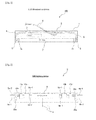
- Fig. 1 shows the LED illumination system 100
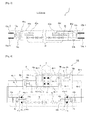
- Fig. 2 is a block diagram showing the circuit arrangement of the LED lighting device 3
- Fig. 3 shows the schematic structure of the LED lamp 7
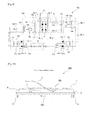
- Fig. 4 is a schematic circuit diagram showing the whole LED illumination system 100
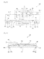
- Fig. 5 shows the results of a calculation of voltages Vi across the measuring resistors 13a and 13b, calculated corresponding to the measuring resistors 13a and 13b.
- the LED illumination system 100 is configurated in such a manner that the LED lighting device 3 is installed in the existing straight-tube fluorescent lamp luminaire 1; the input electric wires 4 which are connected to the commercial power supply and to the existing ballast 2 (fluorescent lamp lighting device), and the in total four output electric wires 6 which are connected between the ballast 2 and the sockets 5, are removed and re-connected to the LED lighting device 3; and the LED lamp 7 (hereinafter sometimes referred to merely as "lamp”) is connected to the existing sockets 5.
- the LED lamp 7 hereinafter sometimes referred to merely as "lamp
- the ballast 2 (fluorescent lamp lighting device) can be either removed from the straight-tube fluorescent lamp luminaire 1, or left as it is.
- the LED lamp 7 has a plurality of LEDs and is constituted in such a manner that its end structure (bases, base pins, etc.), its dimensions, etc. are matched to the whole length of a straight-tube fluorescent lamp, and, as a whole, it assumes a shape similar to that of a straight-tube fluorescent lamp, so that it can be attached to two sockets 5 on both ends.
- the LED lamp 7 comprises bases 7a, 7b with pairs of metal pins (a pair of pins 12a-1, 12a-2 and a pair of pins 12b-1, 12b-2 (see Fig. 3 )) on both ends of the slender rod-type body structure inside which or on the surface of which LEDs 16 are arranged in series.
- the LED lamp 7 also has the total length specified in JIS C7617-2 and the base dimensions specified as G13 or G5 in JIS C7709-1.
- the LED lamp 7 does not use a filament. Therefore, basically, one pin (base pin) on each side, which totals two pins for both sides, suffice. However, in order to achieve a structure similar to that of a straight-tube fluorescent lamp, the LED lamp 7 is provided with two pins (base pins) on each side, meaning four pins in total. The details of the LED lamp 7 will be explained later.
- the LED lighting device 3 is constituted in such a manner that, for example, the input electric wires 4 accommodating an AC of 100 V are initially connected to a rectifying circuit 8. Then, the input is converted into a direct current and outputted to intermediate output electric wires 9a-1, 9a-2, 9b-1 and 9b-2 on both sides in Fig. 2 .
- the rectifying circuit 8 comprises, as shown e.g. in Fig. 4 , a diode bridge 31 performing full-wave rectification and a not illustrated smoothing circuit, thus outputting a direct current to output electric wires 6b-1, 6a-1, etc.
- the output electric wires 6b-1 and 6a-1 supply electric power to the LED lamp 7 via the sockets 5.
- a connection judging signal generator 10a comprises voltage-dividing resistors 10a-1 and 10a-2
- a connection judging signal generator 10b comprises voltage-dividing resistors 10b-1 and 10b-2.
- the connection judging signal generator 10a outputs a divided DC voltage to the pair of output electric wires 6a-1, 6a-2
- the connection judging signal generator 10b outputs a divided DC voltage to the pair of output electric wires 6b-1, 6b-2.
- connection judging signal generators 10a and 10b are connected in parallel with the positive pole (the upper side in Fig. 4 ) and the negative pole (the lower side in Fig. 4 ) of the diode bridge 31.
- the voltage-dividing resistor 10a-1 is connected to the positive pole side of the diode bridge 31, while the voltage-dividing resistor 10a-2 is connected to the negative pole side of the diode bridge 31.
- the voltage-dividing resistor 10b-2 is connected to the positive pole side of the diode bridge 31, while the voltage-dividing resistor 10b-1 is connected to the negative pole side of the diode bridge 31.
- a voltage measurement and cut-off signal generation circuit 11a (impedance detection means) connected in parallel with the voltage-dividing resistor 10a-2 of the connection judging signal generator 10a measures the voltage between the output electric wires 6a-1 and 6a-2. If this voltage is outside of the predetermined range (described later), the voltage measurement and cut-off signal generation circuit 11a sends a cut-off signal via a signal line 34a to a cut-off circuit 35a (protection means). The cut-off circuit 35a then cuts off the connection to the output electric wires 6a-1 and 6a-2.
- the voltage measurement and cut-off signal generation circuit 11b (impedance detection means) connected in parallel with the voltage-dividing resistor 10b-2 of the connection judging signal generator 10b measures the voltage between the output electric wires 6b-1 and 6b-2. If this voltage is outside of the predetermined range (described later), the voltage measurement and cut-off signal generation circuit 11b sends a cut-off signal via a signal line 34b to a cut-off circuit 35b (protection means). The cut-off circuit 35b then cuts off the connection to the output electric wires 6b-1 and 6b-2. Since the measured voltages depend on the impedance of the measuring resistors provided in the LED lamp 7, this means that the impedance is measured indirectly.
- the voltage measurement circuit portions of the voltage measurement and cut-off signal generation circuits 11a and 11b are designed to measure a time-averaged DC voltage of more than 50 Hz. In case of an AC voltage, 0 V is measured. Furthermore, according to one example, in order to avoid the influences of noise, transitional changes, etc., the average is taken for a long period of time of about 0.5 seconds.
- the cut-off circuits 35a and 35b they e.g. once perform a cut-off, are retained in this state until the power supply is turned off, and when the power supply is turned on next time, they are reset and put in the conductive state. According to another example, a reset switch may be provided and the cut-off state held until the reset switch is pushed.
- This LED lighting device 3 outputs the electric power which is outputted to each socket 5 and allows the LEDs to emit light, to one of the two output electric wires 6a-1, 6a-2 and one of the output electric wires 6b-1, 6b-2; in Fig. 4 the output electric wires 6a-1 and 6b-1.
- the LED lamp 7 comprises one pair of pins (the pair of pins 12a-1, 12a-2 and the pair of pins 12b-1, 12b-2) on each end, which totals four pins 12a-1, 12a-2, 12b-1 and 12b-2. They can be connected to the sockets 5 on the side of the luminaire to support the LED lamp 7.
- the conditions for fitting into the straight-tube fluorescent lamp luminaire 1 such as the dimensions of the tube end portions including the pins 12a-1, 12a-2, 12b-1, 12b-2, the whole length of the lamp, etc. are described in JIS C7617-1 or -2 which specify straight-tube fluorescent lamps, and in JIS C7709-1 which specifies bases. These conditions are fulfilled.
- the pins 12a-1 and 12a-2 are each connected to one end of the impedance, i.e. the measuring resistor 13a in this example.
- the pins 12b-1 and 12b-2 are each connected to one end of the measuring resistor 13b.
- the measuring resistors 13a and 13b are connected in parallel to detection means 14a and 14b (lighting device output detection means) of the LED lighting device 3, respectively.
- the detection means 14a and 14b are e.g. voltmeters and, in this case, they indirectly measure the output or the output characteristic of the LED lighting device. In case the output deviates from a predetermined voltage range corresponding to a predetermined output of the LED lighting device, the cut-off signal for cutting off the electric power is generated and supplied to the cut-off signal lines 44a and 44b.
- the sections between the pins 12a-1 and 12a-2 and between the pins 12b-1 and 12b-2 are referred to as inter-terminal section A, respectively.
- the input sorting circuit 41a comprises two diodes 41a-1, 41a-2, while the input sorting circuit 41b comprises two diodes 41b-1, 41b-2.
- the electric power for allowing the LED to emit light which is supplied from the LED lighting device 3, is outputted to one of the pins 12a-1, 12a-2 or one of the pins 12b-1, 12b-2. In any case, the electric power is properly supplied to the LED.
- the output electric wire 6b-1 is the line supplying the electric power.
- the voltage in the output electric wire 6b-1 is higher than that in the output electric wire 6b-2 due to the voltage-dividing resistors 10b-1 and 10b-2. Therefore, the voltage becomes higher in a diode 41b-1 than in a diode 41b-2, so that the former (diode 41b-1) is in the conductive state and the latter (diode 41b-2) is in the cut-off state.
- the output electric wire 6b-1 is connected to the cut-off circuit 43b.
- the diode 41b-2 is cut-off from the output electric wire 6b-1 and therefore does not influence the connection from the output electric wire 6b-2 to the detection means 14b.
- the path through which the current flows in the LED illumination system 100 in Fig. 4 leads from the positive pole (the upper side in Fig. 4 ) of the diode bridge 31 to the cut-off circuit 35b, the output electric wire 6b-1, the diode 41b-1, the cut-off circuit 43b, a current control circuit 15, a plurality of light emitting diodes 16, the cut-off circuit 43a, the diode 41a-2, the detection means 14a, the output electric wire 6a-1, the cut-off circuit 35a, and the negative pole (the lower side in Fig. 4 ) of the diode bridge 31.
- the LED lamp 7 may be fitted in reverse in front-back-direction (the vertical direction in Fig. 4 ) with regard to the direction of the LED lamp 7 in Fig. 4 .
- the path through which the current flows leads from the positive pole (the upper side in Fig. 4 ) of the diode bridge 31 to the cut-off circuit 35b, the output electric wire 6b-1, the diode 41b-1, the cut-off circuit 43b, the current control circuit 15, the plurality of diodes 16, the cut-off circuit 43a, the diode 41a-1, the detection means 14a, the output electric wire 6a-1, the cut-off circuit 35a, and the negative pole (the lower side in Fig. 4 ) of the diode bridge 31.
- the state of the LED lamp 7 in left-right-direction is limited to one direction.
- the electric potential in the LED lighting device 3 in Fig. 4 becomes higher on the right side than on the left side. Therefore, the current does not flow through the LED lamp 7 and the LED lamp 7 is not lit.
- the detection means 14a and 14b are designed to measure a time-averaged DC voltage of more than 50 Hz. In case of an AC voltage, 0 V is measured. Furthermore, according to one example, in order to avoid the influences of noise, transitional changes, etc., the average is taken for a long period of time of about 0.5 seconds.
- the cut-off circuits 43a and 43b (protection means) cut off the electric power sent from the output electric wires 6a-1 and 6b-1.
- the current control circuit 15 and the plurality of light emitting diodes 16 are connected in series and control is executed to realize an appropriate current so that the light emitting diodes 16 emit light properly.
- the current control circuit 15 is a resistor. In order to further stabilize the emission output, it may also be a fixed current circuit.
- the cut-off circuits 43a and 43b are designed so that they e.g. once perform a cut-off, are retained in this state until the power supply is turned off, and when the power supply is turned on next time, they are reset and put in the conductive state.
- a reset switch may be provided and the cut-off state held until the reset switch is pushed.
- LED luminaire adapted to an overall lamp length of 1198 mm, to which FLR40S, FL40S, FL40SS/37, FHF32, etc. specified in JIS C7617-2 can be attached.
- the LED lighting device 3 outputs a connection judging signal from the connection judging signal generators 10a and 10b to at least one pair of the in total four output electric wires 6a-1, 6a-2, 6b-1, 6b-2; for example in Fig. 2 or Fig. 4 , the pair of output electric wires 6a-1, 6a-2 and the pair of output electric wires 6b-1, 6b-2, each pair being connected to a socket 5 on the same end.
- the connection judging signal generator 10a the connection judging signal is outputted to the pair of output electric wires 6a-1 and 6a-2.
- the connection judging signal is outputted to the pair of output electric wires 6b-1 and 6b-2.
- connection judging signal generator 10a is, for example, a circuit where the output impedance of a direct current generated by the voltage-dividing resistors 10a-1 and 10a-2 generates a limited voltage. That the output impedance is limited means that the generated voltage changes depending on the impedance of the circuit connected to the output side.
- connection judging signal generator 10b is, for example, a circuit where the output impedance of a direct current generated by the voltage-dividing resistors 10b-1 and 10b-2 generates a limited voltage.
- the voltage-dividing resistors 10a-1, 10a-2, 10b-1, 10b-2 are 90 k ⁇ , 15 k ⁇ , 90 k ⁇ , and 15 k ⁇ , respectively (referred to as Rd11, Rd12, Rd21, and Rd22, respectively).
- Rd11 (voltage-dividing resistor 10a-1) 90 k ⁇
- Rd12 (voltage-dividing resistor 10a-2) 15 k ⁇
- the voltage range where the voltage measurement and cut-off signal generation circuits 11a, 11b and the detection means 14a, 14b of the LED lamp 7 do not generate a cut-off signal is set to 6.0 V - 12.0 V.
- the voltage V0 outputted by the rectifying circuit 8 changes, due to the load, from 100 V to 141 V in case it is a smoothing circuit comprising a full-wave rectification circuit of four diodes, and a simple capacitor.
- i is 1 or 2, which correspond to the left and right circuit, respectively.
- No. 1 - No. 6 are the results of calculations of the in total six combinations, namely of the above three values of the measuring resistors 13a and 13b (18 k ⁇ , 15 k ⁇ , 12 k ⁇ ) and the two cases of 141 V and 100 V, which are the maximum and minimum values of the voltage V0 outputted by the rectifying circuit 8.
- Fig. 5 shows that the voltage Vi is in the range from 6.90 V to 11.75 V. Therefore, it falls within the range from 6.0 V to 12.0 V where the LED lighting device 3 and the LED lamp 7 are not cut off. Since no cut-off signal is generated, the respective cut-off circuits 35a, 35b and 43a, 43b do not break the circuits, so that in the end, electric power is fed to the LEDs 16 and they emit light.
- the resistance on one end of the straight-tube fluorescent lamp (the resistance between the two base pins, i.e. the resistance of the filament) is about 1.5 ⁇ - 4 ⁇ , at its maximum at most 100 ⁇ , at room temperature and about five times that when a current flows and the temperature rises.
- the overall resistance is 1.5 ⁇ to 500 ⁇ .
- the resistance in an abnormal state, may be ⁇ ⁇ or at least 500 ⁇ in case the filament has burnt out due to e.g. it being at the end of its life, or the resistance may be 0 ⁇ or at most 0.5 ⁇ in an abnormal case of short-circuiting, including the end of life.
- the possible resistance ranges from 0 ⁇ to 500 ⁇ or is at least 500 k ⁇ .
- the possible resistance values are either in the range from 0 ⁇ to 500 ⁇ or at least 500 k ⁇ .
- the voltage V1 or V2 across the measuring resistor 13a or 13b at this time is as follows:
- the above ranges (1) and (2) deviate from the voltage range of 6.0 V - 12.0 V where the voltage measurement and cut-off signal generation circuits 11a, 11b of the LED lighting device 3 do not generate a cut-off signal. Therefore, the voltage measurement and cut-off signal generation circuits 11a, 11b of the LED lighting device 3 generate the cut-off signal, so that the cut-off circuits 35a, 35b break the circuits and the output to the straight-tube fluorescent lamp is cut off.
- No. 13 - No. 16 in Fig. 5 show the results of calculations of the measuring resistance Rmi, wherein the minimum value (6.0 V) and the maximum value (12.0 V) of the range from 6.0 V to 12.0 V where the voltage measurement and cut-off signal generation circuits 11a, 11b of the LED lighting device 3 do not generate a cut-off signal, are achieved.
- the range from 500 ⁇ to 500 k ⁇ may be observed for a short period of time. However, this value changes to at most 500 ⁇ or at least 100 k ⁇ during this short period of time, and therefore, the current is cut off for a short period of time. Thus, for the resistance value which the straight-tube fluorescent lamp can assume, the range from 500 ⁇ to 500 k ⁇ can be excluded.
- the optimum resistance value ranges of the measuring resistors 13a, 13b (Rm1, Rm2) in both the normal and abnormal states of the straight-tube fluorescent lamp are from 0 ⁇ to 500 ⁇ and at least 500 k ⁇ , as described above.
- the range from 500 ⁇ to 500 k ⁇ may be observed for a short period of time. However, this value changes to at most 500 ⁇ or at least 100 k ⁇ during this short period of time, and therefore, the current is cut off for a short period of time. Thus, this case is excluded.
- the resistance value range may be approximately 50 ⁇ to 1 M ⁇ .
- the output to the pair of terminals for each socket 5 of the straight-tube fluorescent lamp luminaire 1 is an alternating current with a commercial frequency or a high frequency for all lamps of a glow tube type, rapid type and inverter type.
- the detection means 14a, 14b of the present LED lamp 7 detect a value only for a voltage of a direct current and measure 0 V in case of an alternating current.
- the detection means 14a, 14b Since the voltage range where the detection means 14a, 14b do not generate cut-off signals is from 6.0 V to 12.0 V, the detection means 14a, 14b generate cut-off signals which are sent to the cut-off circuits 43a, 43b, and the electric power is cut off.
- the cut-off signals from the detection means 14a, 14b are sent through the cut-off signal lines 44a, 44b to the cut-off circuits 43a, 43b which cut off the electric power sent through the output electric wires 6a-1, 6b-1.
- the LED lamp 7 As described above, in case the LED lamp 7 is attached to the unconverted straight-tube fluorescent lamp luminaire 1, the LED lamp 7 breaks the circuit and the voltage/current are cut off. Therefore, accidents such as heat generation and smoke emission do not occur.
- both the LED lighting device 3 side and the LED lamp 7 side may be put in the cut-off state, the voltage, etc. checked, and after it is judged to be out of the range, the conductive state realized. Although in the latter case, it takes some time until the lamp emits light after it is switched on, it is safer.
- both cut-off circuits 43a and 43b on the LED lamp 7 side are put in the cut-off state, and one of the cut-off circuits 35a and 35b on the LED lighting device 3 side, e.g. the cut-off circuit 35a, is put in the conductive state.
- the other cut-off circuit 35b is put in the conductive state and further checking is performed on the LED lamp 4 side.
- the reason why only one of the cut-off circuits 35a and 35b on the LED lighting device 3 side is opened at the beginning, is: The cut-off circuits 35a and 35b must be put in the conductive state for performing the checking. However, if they are put in the conductive state at the same time, a current flows temporarily if a lamp other than the predetermined LED lamp 7 is mistakenly attached. The above prevents problems from occuring at this time.
- a voltage measurement and cut-off signal generation circuit 11a, 11b and a connection judging signal generator 10a, 10b are provided on each ends of the LED lighting device 3.
- a detection means 14a, 14b and a measuring resistor 13a, 13b is provided on each end of the LED lamp 7. They are effective even if they are only provided on either side in the LED lighting device 3 and the LED lamp 7, but it is safer if they are provided on both sides.
- the outputs of the connection judging signal generators 10a and 10b use a signal obtained by dividing a wide voltage using resistors.
- a fixed current source may be used, in which case the detection can be performed more precisely.
- a signal of a specific frequency may be used and, correspondingly, not a resistance but a capacitor may be used as an element for setting the impedance on the LED lamp side.
- Figs. 6 - 9 show Embodiment 2.
- Fig. 6 shows the LED illumination system 200.
- Fig. 7 is a block diagram showing the circuit arrangement of the LED lighting device 203.
- Fig. 8 shows the schematic structure of the LED lamp 207.
- Fig. 9 is a schematic circuit diagram showing the whole LED illumination system 200.
- the LED illumination system 200 is configurated in such a manner that the LED lighting device 203 is installed in the existing straight-tube fluorescent lamp luminaire 1, the input electric wires 4 which are connected to the commercial power supply and to the existing ballast 2 (fluorescent lamp lighting device), and the in total four output electric wires 6 which are connected between the ballast 2 and the sockets 5, are removed and re-connected to the LED lighting device 203, and the LED lamp 207 (hereinafter sometimes referred to merely as "lamp”) is connected to the existing sockets 5.
- the LED lamp 207 hereinafter sometimes referred to merely as "lamp
- the LED illumination system 200 differs from the LED illumination system 100 in the LED lighting device 203 and the LED lamp 207.
- the LED lighting device 203 comprises the rectifying circuit 8, the connection judging signal generators 10a, 10b, the voltage measurement and cut-off signal generation circuits 11a, 11b, the cut-off circuits 35a, 35b, and the current control circuit 15.
- the input electric wires 4 accomodating an AC of 100 V are initially connected to the rectifying circuit 8, and the electric power is converted into a direct current to be outputted to the intermediate output electric wires 9a-1, 9a-2, 9b-1 and 9b-2 on both sides in Fig. 7 .
- the current control circuit 15 is electrically connected between the rectifying circuit 8 and the connection judging signal generator 10b and controls the current, i.e. the electric power, flowing through the LEDs 16 with the help of a fixed current circuit or a current limiting resistor.
- the LED lamp 207 side does not include the current control circuit 15 but comprises the LEDs 16 and the safety circuits, namely the measuring resistors 13a, 13b, the detection means 14a, 14b, the input sorting circuits 41a, 41b, and the cut-off circuits 43a, 43b.
- the LED illumination system 200 comprises the LED lighting device 203 and the LED lamp 207.
- the rectifying circuit 8 and the connection judging signal generators 10a, 10b of the LED lighting device 203 as well as the input sorting circuits 41a, 41b of the LED lamp 207 are the same as those of the LED illumination system 100 in Fig. 4 .
- the operation of lighting the LEDs 16 is identical to that of Embodiment 1, provided, however, that the current control circuit 15 on the LED lamp 7 side in Embodiment 1 is provided in the LED lighting device 203.
- the current control circuit 15 is a fixed current circuit
- the current control circuit 15 is a resistor
- the resistance values are 50 ⁇ and 25 ⁇ for 20 W and 40 W, respectively.
- the fixed current circuit of the current control circuit 15 becomes conductive.
- the resistance is very small in comparison with Rdi1, etc. In either case, there is hardly any change compared to the state where the current control circuit 15 is not included.
- the voltage drop caused by the current control circuit 15 is about 10% of the power supply voltage in any system in the above example. Therefore, for the right-side circuit in Fig. 9 , the voltage applied to the voltage-dividing resistors 10b-1 and 10b-2 is reduced by 10%, and the current flowing through the measuring resistor 13b decreases by 10%. Thus, the voltages detected by the detection means 14b on the LED lamp 207 side and the voltage measurement and cut-off signal generation circuits 11a, 11b on the LED lighting device 203 side are reduced by 10%. Thus, according to one example, the minimum value of the cut-off judging voltage is lowered by 10%.
- the left-side circuit in Fig. 9 is identical to the one in Embodiment 1. Any side operates in the same way as Embodiment 1.
- Figs. 10 - 13 show Embodiment 2.
- Fig. 10 shows the LED illumination system 300.
- Fig. 11 is a block diagram showing the circuit arrangement of the LED lighting device 303.
- Fig. 12 shows the schematic structure of the LED lamp 307.
- Fig. 13 is a schematic circuit diagram showing the whole LED illumination system 300.
- the LED illumination system 300 is configurated in such a manner that the LED lighting device 303 is installed in the existing straight-tube fluorescent lamp luminaire 1, the input electric wires 4 which are connected to the commercial power supply and to the existing ballast 2 (fluorescent lamp lighting device) and the in total four output electric wires 6 which are connected between the ballast 2 and the sockets 5 are removed and re-connected to the LED lighting device 303, and the LED lamp 307 (hereinafter sometimes referred to merely as "lamp”) is connected to the existing sockets 5.
- the LED lamp 307 hereinafter sometimes referred to merely as "lamp
- the LED illumination system 300 differs from the LED illumination system 100 in the LED lighting device 303 and the LED lamp 307.
- the LED lighting device 303 comprises the connection judging signal generators 10a, 10b, the voltage measurement and cut-off signal generation circuits 11a, 11b, and the cut-off circuits 35a, 35b.
- the rectifying circuit 8 and the current control circuit 15 are provided in the LED lamp 307.
- the alternating current is used as it is.
- the output electric wires 6a-1 and 6b-1 accommodate a commercial voltage of a AC of 100 V as it is.
- the output electric wires 6a-1, 6a-2, 6b-1 and 6b-2 are connected to the bases of the LED lamp 7 via the sockets 5. Furthermore, the measuring resistors 13a, 13b, the RF conduction capacitors 45a, 45b and the detection means 14a, 14b are connected in parallel and connected to the rectifying circuit 8 via the input sorting circuits 41a, 41b and the cut-off circuits 43a, 43b. While the voltage inputted into the rectifying circuit 8 is kept at an AC of 100 V, it is rectified here and further smoothed in some cases to be outputted to the series circuit of the current control circuit 15 and the LEDs 16. Then, because of the controlled direct current, the LEDs 16 emit light.
- connection judging signal generators 10a and 10b consist of the voltage-dividing resistors 10a-1, 10a-2, 10b-1 and 10b-2 and, since the input is an AC of 100 V, an alternating current is outputted.
- the cut-off circuits 35a and 35b are in the conductive state, they are connected to the measuring resistors 13a and 13b via the output electric wires 6a-1, 6a-2, 6b-1 and 6b-2. Consequently, for the inputted AC voltage, voltages that are determined independently on both ends (the left and right sides in Fig. 13 ) by three resistances and one capacitor, i.e.
- the voltage-dividing resistors 10a-1, 10a-2, the measuring resistor 13a and the RF conduction capacitor 45a on the left side in Fig. 13 and the voltage-dividing resistors 10b-1, 10b-2, the measuring resistor 13b and the RF conduction capacitor 45b on the right side, are generated at the measurement positions of the voltage measurement and cut-off signal generation circuits 11a, 11b and the detection means 14a, 14b.
- the voltage measurement and cut-off signal generation circuits 11a, 11b and the detection means 14a, 14b are AC voltmeters in this example.
- the resistors of Embodiment 1 are used as they are. Furthermore, the RF conduction capacitors 45a, 45b are set to such capacitances that conduction hardly takes place at commercial frequencies, so that the DC voltage is replaced with the effective value of the AC voltage, and the measurement is performed for this value.
- the RF conduction capacitors 45a and 45b lower the voltage by about 10%, which can be neglected in certain cases. In cases where it cannot be neglected, particularly the minimum value of the range from 6.0 V to 12.0 V where the cut-off signal is not generated, should be lowered by about 10% (5.4 V - 12.0 V), depending on the capacitances of the RF conduction capacitors 45a and 45b.
- the detection means 14a and 14b detect the voltage applied to the filament of the straight-tube fluorescent lamp, as it is.
- ballast 2 fluorescent lamp lighting device
- glow-tube type about 200 V are applied to the terminals on both ends of the lamp, and the discharge lines of the glow tube and the measuring resistors 13a, 13b at both ends become serial.
- the discharge voltage of the glow tube is about 150 V and the voltages across the measuring resistors 13a and 13b are about 25 V, respectively. Since, as in Embodiment 1, the cut-off signal is not generated in the range from 6.0 V to 12.0 V, a cutting-off is carried out.
- a filament transformer In a fluorescent lamp lighting device of a rapid start type, a filament transformer independently generates a voltage for heating the filament and applies it to the filament. JIS C7617-2 stipulates that this voltage is from 3.4 V to 4.2 V. Thus, this value deviates from the range from 6.0 V to 12.0 V where the cut-off signal is not generated. Therefore, the circuit is broken.
- the fluorescent lamp lighting device is an inverter type, it is connected to something which is not a filament, which is why a wide range of voltages may be generated.
- the RF conduction capacitors 45a and 45b are provided, the value of this voltage may possibly be within the range from 6.0 V to 12.0 V where the cut-off signal is not generated.
Landscapes
- Circuit Arrangement For Electric Light Sources In General (AREA)
- Non-Portable Lighting Devices Or Systems Thereof (AREA)
- Arrangement Of Elements, Cooling, Sealing, Or The Like Of Lighting Devices (AREA)
Abstract
Description
- The present invention relates to a LED illumination system of the type where a LED (Light Emitting Diode) lighting device is added to an existing straight-tube fluorescent lamp luminaire and a LED lamp is fitted into the existing sockets. The present invention also relates to the LED lamp and the LED lighting device which constitute the LED illumination system.
-
Fig. 14 shows a conventionalLED illumination system 400 described ine.g. Patent Document 1 andPatent Document 2. As shown inFig. 14 , in a conventionalLED illumination system 400, a ballast 402 (fluorescent lamp lighting device) of an existing straight-tube fluorescent lamp luminaire 401 (hereinafter sometimes referred to merely as "luminaire") is removed and, in its stead, aLED lighting device 403 is installed. As to the wiring, inputelectric wires 404 from a commercial power supply to theballast 402 and outputelectric wires 406 from theballast 402 to twosockets 405 on both ends are directly connected to theLED lighting device 403. Furthermore, the conventionalLED illumination system 400 comprises a LED lamp 407 (hereinafter sometimes referred to merely as "lamp") installed between thesockets 405, saidLED lamp 407 having LEDs (Light Emitting Diodes), being constructed to have its end structure (bases, base pins, etc.), its dimensions, etc. matched to the whole length of a straight-tube fluorescent lamp, and, as a whole, assuming a shape similar to that of a straight-tube fluorescent lamp, so that it can be attached to two sockets 205 on both ends. - When a predetermined voltage is applied to the
LED lighting device 403 from the commercial power supply via the inputelectric wires 404, electric power is supplied from theLED lighting device 403 tobases LED lamp 407 via thesockets 405 on both ends. Then, the installed LEDs emit light and are used for illumination. - According to
Patent Document 1, an adapter for identification is provided between thesockets 405 and thebases - According to
Patent Document 2, thebases LED lamp 407, lead wires are provided seperately, and thus, theLED lighting device 403 and theLED lamp 407 are electrically connected. - In case of a straight-tube fluorescent lamp, both ends of filaments provided on both its ends must be further connected independently to the ballast 402 (fluorescent lamp lighting device). Therefore, two output
electric wires 406 and two terminals in thesocket 405 are needed on each side. Namely, four output electric wires and four terminals in the sockets are needed in total for both sides. - On the other hand, for the
LED lamp 407, basically, two independent connections suffice. However, theLED lamp 407 shown inFig. 14 is constructed by combining a straight-tube fluorescent lamp with an end structure (base, base pins, etc.). Herein, for example, one of the two base pins on one side is a dummy base pin. Thus, in the case where theLED lamp 407 is connected to the two outputelectric wires 406 and the two terminals in asocket 405 on each side, which totals four of each for both sides, it may in some cases not be possible to connect theLED lighting device 403 to theLED lamp 407, depending on the insertion direction. - As one example for preventing the above problem, electric power is supplied to both ends, and a short circuit is created in the
LED lighting device 403 or theLED lamp 407 beforehand, so that the respective two of the four output electric wires that are connected to thesame socket 405 are set to the same electric potential. - Since it is necessary to operate the LED with a direct current and in such a manner that the current is controlled, the above LED illumination system requires an AC-DC conversion means, a voltage conversion means and a current control means between the commercial power supply and the LED. Depending on how these means are allotted on the luminaire side and the lamp side, the following types emerge.
- In the "First Type", almost all means are located on the luminaire side and a controlled direct current is supplied to the lamp side.
- In the "Second Type", the AC-DC conversion is performed on the luminaire side and a voltage with an appropriate value is supplied to the lamp side, while the lamp side has the current control means.
- In the "Third Type", the current passes through the luminaire side almost without stopping and the lamp side has almost all the functions.
-
- Patent Document 1:
JP Pat. Appl. Publ. No. 2009-004342 - Patent Document 2:
JP Pat. Appl. Publ. No. 2004-303614 - In the LED illumination system of this kind, the
LED lamp 407 can be fitted to the original straight-tubefluorescent lamp luminaire 401 in which the ballast 402 (fluorescent lamp lighting device) has not been replaced with theLED lighting device 403. Conversely, the straight-tube fluorescent lamp can also be fitted after theballast 402 is replaced with theLED lighting device 403. In case the lamp is thus mistakenly fitted, some characteristic problems occur as a matter of course. For example, no light is emitted, the light is dim, the lifetime becomes shorter, etc. Furthermore, in certain cases, phenomena which influence safety, such as components generating abnormal heat, may occur. - In case the
LED lamp 407 is fitted to the straight-tubefluorescent lamp luminaire 401 in which the ballast 402 (fluorescent lamp lighting device) has not been replaced with theLED lighting device 403, the following phenomena occur for the "First Type" to the "Third Type": - (1) "First Type":
- Since the
LED lamp 407 does not have a special control circuit besides the LEDs, the LEDs burn out in a short time. During this process, the temperature rises abnormally and in some cases, there is a possibility of smoke emission and ignition.
- Since the
- (2) "Second Type" and "Third Type":
- Though the current is controlled by the control circuit in the
LED lamp 407, a voltage higher than a predetermined voltage may be applied and there is a possibility of smoke emission and ignition caused by the insulation breaking down.
- Though the current is controlled by the control circuit in the
- On the other hand, when in the case where a straight-tube fluorescent lamp is fitted into the straight-tube
fluorescent lamp luminaire 401 in which theballast 402 has been replaced with theLED lighting device 403, a voltage is applied that exceeds the discharge voltage of the straight-tube fluorescent lamp, a discharge takes place in any of the above types. In the "Third Type", an overcurrent flows. In the "First Type" and the "Second Type", a too small DC current or an excessive DC current flows. Therefore, the lifetime becomes shorter and, in certain cases, thesockets 405, etc. can be damaged because of the temperature rise. - According to
Patent Document 1, as a safety countermeasure, adapters are provided between thesockets 405 and thebases bases - In
Patent Document 2, thebases Patent Document 2 has the disadvantage that it is necessary to bore holes into the straight-tubefluorescent lamp luminaire 401, through which lead wires for connecting theLED lighting device 403 provided inside the straight-tubefluorescent lamp luminaire 401 to theLED lamp 407 provided outside thereof, are allowed to pass. - The present invention is intended for solving the above problems. It provides a LED illumination system and a LED lighting device which do not cause heat generation and damage even when a straight-tube fluorescent lamp is mistakenly fitted into a straight-tube fluorescent lamp luminaire in which the fluorescent lamp ballast has been replaced with a LED lighting device. Further, the present invention provides a LED lamp which does not cause heat generation and damage even when it is mistakenly fitted into a straight-tube fluorescent lamp luminaire in which the fluorescent lamp ballast has not been replaced with a LED lighting device.
- The LED illumination system according to the present invention is a LED illumination system wherein a LED lighting device is installed in an existing straight-tube fluorescent lamp luminaire, input electric wires connected to a commercial power supply and output electric wires connected to existing sockets, all wires being connected to the existing fluorescent lamp lighting device, are removed and re-connected to the LED lighting device, and a LED lamp is connected to the sockets; wherein
either inter-terminal section on the ends of the LED lamp is referred to as inter-terminal section A; the characteristic of an output from the LED lighting device connected to the inter-terminal sections A is different from that of the existing fluorescent lamp lighting device; and the LED lamp is provided with lighting device output detection means for detecting the output from the LED lighting device and also with protection means for cutting off an input to the LED lamp when the output detected by the lighting device output detection means is outside of a predetermined range. - In the LED illumination system according to the present invention, the impedance of the inter-terminal sections A of the LED lamp is different from the impedance of a fluorescent lamp, both in a normal state and at the end of its life; impedance detection means for directly or indirectly detecting the impedance of the inter-terminal sections A is provided on the side of the LED lighting device corresponding to the inter-terminal sections A; and, further, the LED lighting device is provided with protection means for cutting off the output of the LED lighting device when the impedance of the inter-terminal sections A detected by the impedance detection means is outside of a predetermined range.
- The LED lamp according to the present invention is a LED lamp with a base provided with a pair of metal pins on each end of a slender rod-type body, inside which or on the surface of which LEDs are arranged in series; said LED lamp having the overall length specified in JIS C7617-2 and the base dimensions specified as G13 or G5 in JIS C7709-1, wherein either inter-terminal section on the ends is referred to as inter-terminal section A; the impedance of the inter-terminal sections A is different from the impedance of a fluorescent lamp, both in a normal state and at the end of its life; lighting device output detection means are provided for detecting an output from the LED lighting device, and protection means are provided for cutting off an input to the LED lamp when the output detected by the lighting device output detection means is outside of a predetermined range.
- In the LED lamp according to the present invention, a resistor of 500Ω to 500kΩ is provided between the two pins of the base of at least one end.
- The LED lamp according to the present invention operates with a DC voltage or current from the LED lighting device, has detection means for detecting whether a voltage applied between the input terminals is an alternating current or a direct current, and has protection means for cutting off if it is an alternating current.
- The LED lamp according to the present invention has detection means for an applied voltage of the inter-terminal sections A connected to the resistors, and protection means for cutting off if the applied voltage deviates from a voltage calculated from a current made to flow by the LED lighting device and from any resistance value in the range of the resistor.
- The LED lighting device according to the present invention has output terminals connected to the bases of the LED lamp; at least part of the output from the output terminals is different from an output of a fluorescent lamp lighting device; it has impedance detection means for measuring the impedance between the terminals of the LED lamp; and it has a protection means for cutting off the output if the impedance between the terminals of the LED lamp detected by the impedance detection means is outside of a predetermined range.
- The LED lighting device according to the present invention outputs an output with a voltage varying depending on a fixed current or a load, at least at the time when it is activated, between at least one pair of terminals connected to a socket, and has detection means for the voltage between the terminals and protection means for cutting off the output if the voltage between the terminals detected by the detection means is outside of a predetermined range.
- The LED illumination system according to the present invention is configurated in such a manner that either inter-terminal section on the ends of the LED lamp is referred to as inter-terminal section A; the characteristic of an output from the LED lighting device connected to the inter-terminal sections A is different from that for the existing fluorescent lamp lighting device; and the LED lamp is provided with lighting device output detection means for detecting the output from the LED lighting device and also with protection means for cutting off an input to the LED lamp when the output detected by the lighting device output detection means is outside of a predetermined range. Therefore, if this LED lamp is mistakenly attached to a normal fluorescent lamp luminaire, the output to the inter-terminal section A is detected and the input is cut off by the protection means, so that heat generation and smoke emission can be prevented from occurring.
- The LED illumination system according to the present invention is configurated in such a manner that the impedance of the inter-terminal section A of the LED lamp is different from the impedance of a fluorescent lamp, both in a normal state and at the end of its life; impedance detection means for directly or indirectly detecting the impedance of the inter-terminal sections A are provided on the side of the LED lighting device corresponding to the inter-terminal sections A; and, further, the LED lighting device is provided with protection means for cutting off the output of the LED lighting device when the impedance of an inter-terminal section A detected by the impedance detection means is outside of a predetermined range. Therefore, if a fluorescent lamp is mistakenly attached to this luminaire with a LED lighting device, the LED lighting device detects the impedance of the inter-terminal section A and the detected impedance is outside of the range of the impedance set for the inter-terminal section A of the LED lamp. Hence, the output to the lamp is cut off by the protection means, so that heat generation and smoke emission can be prevented from occurring.
- The LED lamp according to the present invention is a LED lamp that is interchangeable with a fluorescent lamp from the viewpoint of its size, and is configurated in such a manner that either inter-terminal section on the ends is referred to as inter-terminal section A; the impedance of the inter-terminal sections A is different from the impedance of a fluorescent lamp, both in a normal state and at the end of its life; lighting device output detection means are provided for detecting an output from the LED lighting device, and protection means are provided for cutting off an input to the LED lamp when the output detected by the lighting device output detection means is outside of a predetermined range. Therefore, if this LED lamp is mistakenly attached to a luminaire which still has a fluorescent lamp lighting device, the input is detected and the detection result is outside of the predetermined range. Hence, the output to the lamp is cut off by the protection means, so that heat generation and smoke emission can be prevented from occurring. Further, this impedance is used to allow the LED lighting device side to judge whether or not the lamp is a LED lamp.
- The LED lamp according to the present invention is configurated in such a manner that a resistor of 500Ω to 500kΩ is provided between the two pins of the base on at least one end. Therefore, the LED lighting device can judge whether or not the lamp is a LED lamp by detecting the resistance value. Furthermore, the voltage across the impedance, etc., which is determined by the output from the LED lighting device to the inter-terminal section A and the above impedance, is detected on the side of the LED lamp, thus making it possible to judge whether or not the lamp is a LED lamp.
- The LED lamp according to the present invention is configurated in such a manner that it operates with a DC voltage or current from the LED lighting device, has detection means for detecting whether a voltage applied between the input terminals is an alternating current or a direct current, and has protection means for cutting off if it is an alternating current. Since a fluorescent lamp lighting device uses an alternating current, an alternating current is detected if this LED lamp is mistakenly connected to a fluorescent lamp lighting device, and a cutting-off is performed, so that heat generation and smoking can be prevented from occurring.
- The LED lamp according to the present invention is configurated in such a manner that it has detection means for an applied voltage of the inter-terminal sections A connected to resistors, and protection means for cutting off if the applied voltage deviates from a voltage calculated from a current made to flow by the LED lighting device and from any resistance value in the range of the resistor. Therefore, if the LED lamp is connected to a fluorescent lamp lighting device, the voltage is outside of the range. Then, this voltage is detected and a cutting-off is performed, so that heat generation and smoke emission can be prevented from occurring.
- The LED lighting device according to the present invention is configurated in such a manner that it has output terminals connected to the base of the LED lamp; at least part of the output from the output terminals is different from an output of a fluorescent lamp lighting device; it has impedance detection means for measuring the impedance between the terminals of the LED lamp; and it has protection means for cutting off the output if the impedance between the terminals of the LED lamp detected by the impedance detection means is outside of a predetermined range. Therefore, if a fluorescent lamp is mistakenly attached, this impedance is measured and it is outside of the range of the impedance determined for a LED lamp. Hence, a cutting-off is performed by the protection means, so that heat generation and smoke emission can be prevented from occurring.
- The LED lighting device according to the present invention is configurated in such a manner that it outputs an output with a voltage varying depending on a fixed current or a load, at least at the time when it is activated, between at least one pair of terminals connected to a socket, and which has detection means for the voltage between the terminals and protection means for cutting off the output if the voltage between the terminals detected by the detection means is outside of a predetermined range. Therefore, if a fluorescent lamp is connected, the voltage is outside of the predetermined range. Then, this voltage is detected and a cutting-off is performed, so that heat generation and smoke emission can be prevented from occurring.
-
-
Fig. 1 showsEmbodiment 1 and it shows aLED illumination system 100. -
Fig. 2 showsEmbodiment 1 and is a block diagram showing the circuit arrangement of aLED lighting device 3. -
Fig. 3 showsEmbodiment 1 and it shows the schematic structure of aLED lamp 7. -
Fig. 4 showsEmbodiment 1 and is a schematic circuit drawing showing the wholeLED illumination system 100. -
Fig. 5 showsEmbodiment 1 and it shows the results of a calculation of voltages Vi across measuringresistors resistors -
Fig. 6 showsEmbodiment 2 and it shows aLED illumination system 200. -
Fig. 7 showsEmbodiment 2 and is a block diagram showing the circuit arrangement of aLED lighting device 203. -
Fig. 8 showsEmbodiment 2 and it shows the schematic structure of aLED lamp 207. -
Fig. 9 showsEmbodiment 2 and is a schematic circuit diagram showing the wholeLED illumination system 200. -
Fig. 10 showsEmbodiment 3 and it shows aLED illumination system 300. -
Fig. 11 showsEmbodiment 3 and is a block diagram showing the circuit arrangement of aLED lighting device 303. -
Fig. 12 showsEmbodiment 3 and it shows the schematic structure of aLED lamp 307. -
Fig. 13 showsEmbodiment 3 and is a schematic circuit diagram showing the wholeLED illumination system 300. -
Fig. 14 shows a conventionalLED illumination system 400. - In the LED illumination system according to the present embodiment, the ballast (fluorescent lamp lighting device) of the existing straight-tube fluorescent lamp luminaire is removed, or the input electric wires of the commercial power supply which are connected to the ballast and the output electric wires which are connected to the sockets, are removed. Then, the LED lamp lighting device for lighting an LED lamp is attached, and the input electric wires of the commercial power supply and the output electric wires connected to the sockets are re-connected to the LED lamp lighting device for lighting. To this existing straight-tube fluorescent lamp luminaire in which the ballast (fluorescent lamp lighting device) has been replaced with the LED lamp lighting device, a safe LED lamp to which protection devices, etc. have been added, is attached. As to the LED lamp according to the present embodiment, even when it e.g. is mistakenly attached to an existing straight-tube fluorescent lamp luminaire in which the ballast (fluorescent lamp lighting device) has not been replaced with the LED lamp lighting device, there is no possibility of burnout, smoke emission or ignition, which would take place in case of a conventional LED lamp. Furthermore, in case a straight-tube fluorescent lamp is mistakenly attached to the LED lamp lighting device according to the present embodiment, the LED lamp lighting device measures the impedance of the straight-tube fluorescent lamp and cuts off the connection to the straight-tube fluorescent lamp through the protection means if the impedance of the straight-tube fluorescent lamp is outside of the range of the impedance determined for the LED lamp.
-
Figs. 1-5 show Embodiment 1.Fig. 1 shows theLED illumination system 100,Fig. 2 is a block diagram showing the circuit arrangement of theLED lighting device 3,Fig. 3 shows the schematic structure of theLED lamp 7,Fig. 4 is a schematic circuit diagram showing the wholeLED illumination system 100, andFig. 5 shows the results of a calculation of voltages Vi across the measuringresistors resistors - As shown in
Fig. 1 , theLED illumination system 100 is configurated in such a manner that theLED lighting device 3 is installed in the existing straight-tubefluorescent lamp luminaire 1; the input electric wires 4 which are connected to the commercial power supply and to the existing ballast 2 (fluorescent lamp lighting device), and the in total four outputelectric wires 6 which are connected between theballast 2 and thesockets 5, are removed and re-connected to theLED lighting device 3; and the LED lamp 7 (hereinafter sometimes referred to merely as "lamp") is connected to the existingsockets 5. - At this time, the ballast 2 (fluorescent lamp lighting device) can be either removed from the straight-tube
fluorescent lamp luminaire 1, or left as it is. - The
LED lamp 7 has a plurality of LEDs and is constituted in such a manner that its end structure (bases, base pins, etc.), its dimensions, etc. are matched to the whole length of a straight-tube fluorescent lamp, and, as a whole, it assumes a shape similar to that of a straight-tube fluorescent lamp, so that it can be attached to twosockets 5 on both ends. - The
LED lamp 7 comprisesbases 7a, 7b with pairs of metal pins (a pair ofpins 12a-1, 12a-2 and a pair ofpins 12b-1, 12b-2 (seeFig. 3 )) on both ends of the slender rod-type body structure inside which or on the surface of whichLEDs 16 are arranged in series. TheLED lamp 7 also has the total length specified in JIS C7617-2 and the base dimensions specified as G13 or G5 in JIS C7709-1. - Unlike straight-tube fluorescent lamps, the
LED lamp 7 does not use a filament. Therefore, basically, one pin (base pin) on each side, which totals two pins for both sides, suffice. However, in order to achieve a structure similar to that of a straight-tube fluorescent lamp, theLED lamp 7 is provided with two pins (base pins) on each side, meaning four pins in total. The details of theLED lamp 7 will be explained later. - As shown in
Fig. 2 , theLED lighting device 3 is constituted in such a manner that, for example, the input electric wires 4 accommodating an AC of 100 V are initially connected to arectifying circuit 8. Then, the input is converted into a direct current and outputted to intermediate outputelectric wires 9a-1, 9a-2, 9b-1 and 9b-2 on both sides inFig. 2 . - The rectifying
circuit 8 comprises, as shown e.g. inFig. 4 , adiode bridge 31 performing full-wave rectification and a not illustrated smoothing circuit, thus outputting a direct current to outputelectric wires 6b-1, 6a-1, etc. The outputelectric wires 6b-1 and 6a-1 supply electric power to theLED lamp 7 via thesockets 5. - As shown e.g. in
Fig. 4 , a connection judgingsignal generator 10a comprises voltage-dividingresistors 10a-1 and 10a-2, while a connection judgingsignal generator 10b comprises voltage-dividingresistors 10b-1 and 10b-2. The connection judgingsignal generator 10a outputs a divided DC voltage to the pair of outputelectric wires 6a-1, 6a-2, while the connection judgingsignal generator 10b outputs a divided DC voltage to the pair of outputelectric wires 6b-1, 6b-2. - The connection judging
signal generators Fig. 4 ) and the negative pole (the lower side inFig. 4 ) of thediode bridge 31. In the connection judgingsignal generator 10a, the voltage-dividingresistor 10a-1 is connected to the positive pole side of thediode bridge 31, while the voltage-dividingresistor 10a-2 is connected to the negative pole side of thediode bridge 31. In the connection judgingsignal generator 10b, the voltage-dividingresistor 10b-2 is connected to the positive pole side of thediode bridge 31, while the voltage-dividingresistor 10b-1 is connected to the negative pole side of thediode bridge 31. - On the other hand, a voltage measurement and cut-off
signal generation circuit 11a (impedance detection means) connected in parallel with the voltage-dividingresistor 10a-2 of the connection judgingsignal generator 10a measures the voltage between the outputelectric wires 6a-1 and 6a-2. If this voltage is outside of the predetermined range (described later), the voltage measurement and cut-offsignal generation circuit 11a sends a cut-off signal via asignal line 34a to a cut-off circuit 35a (protection means). The cut-off circuit 35a then cuts off the connection to the outputelectric wires 6a-1 and 6a-2. - Furthermore, the voltage measurement and cut-off
signal generation circuit 11b (impedance detection means) connected in parallel with the voltage-dividingresistor 10b-2 of the connection judgingsignal generator 10b measures the voltage between the outputelectric wires 6b-1 and 6b-2. If this voltage is outside of the predetermined range (described later), the voltage measurement and cut-offsignal generation circuit 11b sends a cut-off signal via asignal line 34b to a cut-off circuit 35b (protection means). The cut-off circuit 35b then cuts off the connection to the outputelectric wires 6b-1 and 6b-2. Since the measured voltages depend on the impedance of the measuring resistors provided in theLED lamp 7, this means that the impedance is measured indirectly. - According to this example, the voltage measurement circuit portions of the voltage measurement and cut-off
signal generation circuits off circuits LED lighting device 3 outputs the electric power which is outputted to eachsocket 5 and allows the LEDs to emit light, to one of the two outputelectric wires 6a-1, 6a-2 and one of the outputelectric wires 6b-1, 6b-2; inFig. 4 the outputelectric wires 6a-1 and 6b-1. - As shown in
Fig. 3 , theLED lamp 7 comprises one pair of pins (the pair ofpins 12a-1, 12a-2 and the pair ofpins 12b-1, 12b-2) on each end, which totals fourpins 12a-1, 12a-2, 12b-1 and 12b-2. They can be connected to thesockets 5 on the side of the luminaire to support theLED lamp 7. - The conditions for fitting into the straight-tube
fluorescent lamp luminaire 1, such as the dimensions of the tube end portions including thepins 12a-1, 12a-2, 12b-1, 12b-2, the whole length of the lamp, etc. are described in JIS C7617-1 or -2 which specify straight-tube fluorescent lamps, and in JIS C7709-1 which specifies bases. These conditions are fulfilled. - The
pins 12a-1 and 12a-2 are each connected to one end of the impedance, i.e. the measuringresistor 13a in this example. Similarly, thepins 12b-1 and 12b-2, too, are each connected to one end of the measuringresistor 13b. - Moreover, the measuring
resistors LED lighting device 3, respectively. The detection means 14a and 14b are e.g. voltmeters and, in this case, they indirectly measure the output or the output characteristic of the LED lighting device. In case the output deviates from a predetermined voltage range corresponding to a predetermined output of the LED lighting device, the cut-off signal for cutting off the electric power is generated and supplied to the cut-off signal lines pins 12a-1 and 12a-2 and between thepins 12b-1 and 12b-2 are referred to as inter-terminal section A, respectively. - As to
input sorting circuits Fig. 4 , theinput sorting circuit 41a comprises twodiodes 41a-1, 41a-2, while theinput sorting circuit 41b comprises twodiodes 41b-1, 41b-2. - The electric power for allowing the LED to emit light, which is supplied from the
LED lighting device 3, is outputted to one of thepins 12a-1, 12a-2 or one of thepins 12b-1, 12b-2. In any case, the electric power is properly supplied to the LED. - At the end on the right side of
Fig. 4 , the outputelectric wire 6b-1 is the line supplying the electric power. Here, the voltage in the outputelectric wire 6b-1 is higher than that in the outputelectric wire 6b-2 due to the voltage-dividingresistors 10b-1 and 10b-2. Therefore, the voltage becomes higher in adiode 41b-1 than in adiode 41b-2, so that the former (diode 41b-1) is in the conductive state and the latter (diode 41b-2) is in the cut-off state. Thus, the outputelectric wire 6b-1 is connected to the cut-off circuit 43b. - On the other hand, the
diode 41b-2 is cut-off from the outputelectric wire 6b-1 and therefore does not influence the connection from the outputelectric wire 6b-2 to the detection means 14b. - The path through which the current flows in the
LED illumination system 100 inFig. 4 leads from the positive pole (the upper side inFig. 4 ) of thediode bridge 31 to the cut-off circuit 35b, the outputelectric wire 6b-1, thediode 41b-1, the cut-off circuit 43b, acurrent control circuit 15, a plurality oflight emitting diodes 16, the cut-off circuit 43a, thediode 41a-2, the detection means 14a, the outputelectric wire 6a-1, the cut-off circuit 35a, and the negative pole (the lower side inFig. 4 ) of thediode bridge 31. - In the
LED illumination system 100 inFig. 4 , theLED lamp 7 may be fitted in reverse in front-back-direction (the vertical direction inFig. 4 ) with regard to the direction of theLED lamp 7 inFig. 4 . In this case, the path through which the current flows leads from the positive pole (the upper side inFig. 4 ) of thediode bridge 31 to the cut-off circuit 35b, the outputelectric wire 6b-1, thediode 41b-1, the cut-off circuit 43b, thecurrent control circuit 15, the plurality ofdiodes 16, the cut-off circuit 43a, thediode 41a-1, the detection means 14a, the outputelectric wire 6a-1, the cut-off circuit 35a, and the negative pole (the lower side inFig. 4 ) of thediode bridge 31. - In the
LED illumination system 100 inFig. 4 , the state of theLED lamp 7 in left-right-direction is limited to one direction. In case theLED lamp 7 is fitted in reverse left-right-direction, the electric potential in theLED lighting device 3 inFig. 4 becomes higher on the right side than on the left side. Therefore, the current does not flow through theLED lamp 7 and theLED lamp 7 is not lit. - According to this example, the detection means 14a and 14b are designed to measure a time-averaged DC voltage of more than 50 Hz. In case of an AC voltage, 0 V is measured. Furthermore, according to one example, in order to avoid the influences of noise, transitional changes, etc., the average is taken for a long period of time of about 0.5 seconds.
- In case the cut-off signals from the detection means 14a and 14b are sent via the cut-
off signal lines off circuits electric wires 6a-1 and 6b-1. Thecurrent control circuit 15 and the plurality oflight emitting diodes 16 are connected in series and control is executed to realize an appropriate current so that thelight emitting diodes 16 emit light properly. In one example, thecurrent control circuit 15 is a resistor. In order to further stabilize the emission output, it may also be a fixed current circuit. - The cut-
off circuits - One example will be concretely explained showing a LED luminaire adapted to an overall lamp length of 1198 mm, to which FLR40S, FL40S, FL40SS/37, FHF32, etc. specified in JIS C7617-2 can be attached.
- The
LED lighting device 3 outputs a connection judging signal from the connection judgingsignal generators electric wires 6a-1, 6a-2, 6b-1, 6b-2; for example inFig. 2 orFig. 4 , the pair of outputelectric wires 6a-1, 6a-2 and the pair of outputelectric wires 6b-1, 6b-2, each pair being connected to asocket 5 on the same end. From the connection judgingsignal generator 10a, the connection judging signal is outputted to the pair of outputelectric wires 6a-1 and 6a-2. Furthermore, from the connection judgingsignal generator 10b, the connection judging signal is outputted to the pair of outputelectric wires 6b-1 and 6b-2. - The connection judging
signal generator 10a is, for example, a circuit where the output impedance of a direct current generated by the voltage-dividingresistors 10a-1 and 10a-2 generates a limited voltage. That the output impedance is limited means that the generated voltage changes depending on the impedance of the circuit connected to the output side. - The connection judging
signal generator 10b is, for example, a circuit where the output impedance of a direct current generated by the voltage-dividingresistors 10b-1 and 10b-2 generates a limited voltage. - For example, with the power supply being an AC of 100 V, the voltage-dividing
resistors 10a-1, 10a-2, 10b-1, 10b-2 are 90 kΩ, 15 kΩ, 90 kΩ, and 15 kΩ, respectively (referred to as Rd11, Rd12, Rd21, and Rd22, respectively). Namely,
Rd11 (voltage-dividingresistor 10a-1) = 90 kΩ
Rd12 (voltage-dividingresistor 10a-2) = 15 kΩ
Rd21 (voltage-dividingresistor 10b-1) = 90 kΩ
Rd22 (voltage-dividingresistor 10b-2) = 15 kΩ - The measuring
resistors normal LED lamp 7 are 15 kΩ ± 3 kΩ (referred to as Rm1 and Rm2, respectively). Namely,
Rm1 (measuringresistor 13a) = 15 kΩ ± 3 kΩ
Rm2 (measuringresistor 13b) = 15 kΩ ± 3 kΩ - The voltage range where the voltage measurement and cut-off
signal generation circuits LED lamp 7 do not generate a cut-off signal, is set to 6.0 V - 12.0 V. - Furthermore, the voltage V0 outputted by the rectifying
circuit 8 changes, due to the load, from 100 V to 141 V in case it is a smoothing circuit comprising a full-wave rectification circuit of four diodes, and a simple capacitor. In this case, the voltages V1 and V2 across the measuringresistors 
Here, i is 1 or 2, which correspond to the left and right circuit, respectively. An example where this calculation was performed corresponding to the maximum value, the center value and the minimum value (18 kΩ, 15 kΩ, 12 kΩ) of the measuringresistors Fig. 5 . - As shown in
Fig. 5 , No. 1 - No. 6 are the results of calculations of the in total six combinations, namely of the above three values of the measuringresistors circuit 8.Fig. 5 shows that the voltage Vi is in the range from 6.90 V to 11.75 V. Therefore, it falls within the range from 6.0 V to 12.0 V where theLED lighting device 3 and theLED lamp 7 are not cut off. Since no cut-off signal is generated, the respective cut-off circuits LEDs 16 and they emit light. - An explanation will be made as to the case where a straight-tube fluorescent lamp is mistakenly fitted to the straight-tube
fluorescent lamp luminaire 1 to which theLED lighting device 3 according toEmbodiment 1 is attached. In the normal state, the resistance on one end of the straight-tube fluorescent lamp (the resistance between the two base pins, i.e. the resistance of the filament) is about 1.5 Ω - 4 Ω, at its maximum at most 100Ω, at room temperature and about five times that when a current flows and the temperature rises. Thus, the overall resistance is 1.5 Ω to 500 Ω. - On the other hand, in an abnormal state, the resistance may be ∞ Ω or at least 500 Ω in case the filament has burnt out due to e.g. it being at the end of its life, or the resistance may be 0 Ω or at most 0.5 Ω in an abnormal case of short-circuiting, including the end of life. Thus, in the normal and abnormal states, the possible resistance ranges from 0 Ω to 500 Ω or is at least 500 kΩ.
- No. 7 - No. 12 in
Fig. 5 show the results of calculations of the voltages Vi (i is 1 or 2) across the measuringresistors circuit 8 = 100 V. - As described above, in the normal and abnormal states of the straight-tube fluorescent lamp, the possible resistance values are either in the range from 0 Ω to 500 Ω or at least 500 kΩ. The voltage V1 or V2 across the measuring
resistor - (1) In case of the range from 0 Ω to 500 Ω (normal state):
- at most 0.53 V (from No. 7 - No. 10 in
Fig. 5 )
- at most 0.53 V (from No. 7 - No. 10 in
- (2) In case of at least 500 kΩ (abnormal state):
- at least 12.66 V (from Nos. 11 and 12 in
Fig. 5 )
- at least 12.66 V (from Nos. 11 and 12 in
- The above ranges (1) and (2) deviate from the voltage range of 6.0 V - 12.0 V where the voltage measurement and cut-off
signal generation circuits LED lighting device 3 do not generate a cut-off signal. Therefore, the voltage measurement and cut-offsignal generation circuits LED lighting device 3 generate the cut-off signal, so that the cut-off circuits - As described above, in case a straight-tube fluorescent lamp is mistakenly fitted to the straight-tube
fluorescent lamp luminaire 1 to which theLED lighting device 3 is attached, the cut-off circuits LED lighting device 3 break the output circuit. Thus, accidents such as heat generation or smoke emission do not occur. - No. 13 - No. 16 in
Fig. 5 show the results of calculations of the measuring resistance Rmi, wherein the minimum value (6.0 V) and the maximum value (12.0 V) of the range from 6.0 V to 12.0 V where the voltage measurement and cut-offsignal generation circuits LED lighting device 3 do not generate a cut-off signal, are achieved. The calculations are performed for: Rdi1 = 90 kΩ, Rdi2 = 15 kΩ, and the voltage V0 outputted by the rectifyingcircuit 8 = 100 V, 141 V. When the voltage V0 = 100 V, the measuring resistance Rmi for realizing the voltage Vi = 6.0 V is 9.3 kΩ, and the measuring resistance Rmi for realizing the voltage Vi = 12.0 V is 67.5 kΩ. Furthermore, when the voltage V0 = 141 V, the measuring resistance Rmi for realizing the voltage Vi = 6.0 V is 5.45 kΩ, and the measuring resistance Rmi for realizing the voltage Vi = 12.0 V is 18.95 kΩ. - When the normal state changes into the abnormal state, the range from 500 Ω to 500 kΩ may be observed for a short period of time. However, this value changes to at most 500 Ω or at least 100 kΩ during this short period of time, and therefore, the current is cut off for a short period of time. Thus, for the resistance value which the straight-tube fluorescent lamp can assume, the range from 500 Ω to 500 kΩ can be excluded.
- Actually, in this example, in case Rdi1 is 90kΩ, only a current of (at most) about 100[V]/90,000[Ω] = 0.001[A] flows through the filament of the straight-tube fluorescent lamp. Therefore, the temperature of the filament of the straight-tube fluorescent lamp hardly rises, and the possible resistance range for the straight-tube fluorescent lamp as a whole becomes narrower. Thus, even if the minimum value is set to 50 Ω - 100 Ω, it is actually very likely that no problems will occur. On the other hand, if the filament of the straight-tube fluorescent lamp breaks, the maximum value of the resistance is at least a few MΩ. It is very likely that no problems will occur until about 1 MΩ is reached.
- Namely, the optimum resistance value ranges of the measuring
resistors - An explanation will be made as to the case where the
LED lamp 7 ofEmbodiment 1 is mistakenly attached to the unconverted straight-tubefluorescent lamp luminaire 1. The output to the pair of terminals for eachsocket 5 of the straight-tubefluorescent lamp luminaire 1 is an alternating current with a commercial frequency or a high frequency for all lamps of a glow tube type, rapid type and inverter type. However, the detection means 14a, 14b of thepresent LED lamp 7 detect a value only for a voltage of a direct current and measure 0 V in case of an alternating current. - Since the voltage range where the detection means 14a, 14b do not generate cut-off signals is from 6.0 V to 12.0 V, the detection means 14a, 14b generate cut-off signals which are sent to the cut-
off circuits off signal lines off circuits electric wires 6a-1, 6b-1. - As described above, in case the
LED lamp 7 is attached to the unconverted straight-tubefluorescent lamp luminaire 1, theLED lamp 7 breaks the circuit and the voltage/current are cut off. Therefore, accidents such as heat generation and smoke emission do not occur. - Immediately after the
LED lighting device 3 is connected to the power supply, it may be put into the conductive state in which the electric power can be fed between the outputelectric wires 6a-1 and 6b-1 and on to the LEDs of theLED lamp 7, the voltage, etc. checked and judged, and in case it is outside of the range, the electric power cut off. Alternatively, immediately after the connection to the power supply is made, both theLED lighting device 3 side and theLED lamp 7 side may be put in the cut-off state, the voltage, etc. checked, and after it is judged to be out of the range, the conductive state realized. Although in the latter case, it takes some time until the lamp emits light after it is switched on, it is safer. As the concrete operation, first, both cut-off circuits LED lamp 7 side are put in the cut-off state, and one of the cut-off circuits LED lighting device 3 side, e.g. the cut-off circuit 35a, is put in the conductive state. After the judgment, the other cut-off circuit 35b is put in the conductive state and further checking is performed on the LED lamp 4 side. The reason why only one of the cut-off circuits LED lighting device 3 side is opened at the beginning, is: The cut-off circuits predetermined LED lamp 7 is mistakenly attached. The above prevents problems from occuring at this time. - According to the example explained in connection with
Embodiment 1, a voltage measurement and cut-offsignal generation circuit signal generator LED lighting device 3. A detection means 14a, 14b and a measuringresistor LED lamp 7. They are effective even if they are only provided on either side in theLED lighting device 3 and theLED lamp 7, but it is safer if they are provided on both sides. - In this example explained in connection with
Embodiment 1, the outputs of the connection judgingsignal generators -
Figs. 6 - 9 show Embodiment 2.Fig. 6 shows theLED illumination system 200.Fig. 7 is a block diagram showing the circuit arrangement of theLED lighting device 203.Fig. 8 shows the schematic structure of theLED lamp 207.Fig. 9 is a schematic circuit diagram showing the wholeLED illumination system 200. - As shown in
Fig. 6 , just as in theLED illumination system 100, theLED illumination system 200 is configurated in such a manner that theLED lighting device 203 is installed in the existing straight-tubefluorescent lamp luminaire 1, the input electric wires 4 which are connected to the commercial power supply and to the existing ballast 2 (fluorescent lamp lighting device), and the in total four outputelectric wires 6 which are connected between theballast 2 and thesockets 5, are removed and re-connected to theLED lighting device 203, and the LED lamp 207 (hereinafter sometimes referred to merely as "lamp") is connected to the existingsockets 5. - The
LED illumination system 200 differs from theLED illumination system 100 in theLED lighting device 203 and theLED lamp 207. - As shown in
Fig. 7 , theLED lighting device 203 comprises the rectifyingcircuit 8, the connection judgingsignal generators signal generation circuits off circuits current control circuit 15. - In the
LED lighting device 203, as shown inFig. 7 , for example, the input electric wires 4 accomodating an AC of 100 V are initially connected to therectifying circuit 8, and the electric power is converted into a direct current to be outputted to the intermediate outputelectric wires 9a-1, 9a-2, 9b-1 and 9b-2 on both sides inFig. 7 . - The
current control circuit 15 is electrically connected between the rectifyingcircuit 8 and the connection judgingsignal generator 10b and controls the current, i.e. the electric power, flowing through theLEDs 16 with the help of a fixed current circuit or a current limiting resistor. - As shown in
Fig. 8 , theLED lamp 207 side does not include thecurrent control circuit 15 but comprises theLEDs 16 and the safety circuits, namely the measuringresistors input sorting circuits off circuits - As shown in
Fig. 9 , theLED illumination system 200 comprises theLED lighting device 203 and theLED lamp 207. The rectifyingcircuit 8 and the connection judgingsignal generators LED lighting device 203 as well as theinput sorting circuits LED lamp 207 are the same as those of theLED illumination system 100 inFig. 4 . - The operation of lighting the
LEDs 16 is identical to that ofEmbodiment 1, provided, however, that thecurrent control circuit 15 on theLED lamp 7 side inEmbodiment 1 is provided in theLED lighting device 203. According to one example where thecurrent control circuit 15 is a fixed current circuit, the conductive state is realized in case the current at the time of lighting is designed as e.g. 20 W, until 0.2 A (0.2 x 100 = 20 W) is reached, and in case it is designed as 40 W, until 0.4 A (0.4 x 100 =40 W) is reached. According to an example where thecurrent control circuit 15 is a resistor, in case the voltage drop caused by the resistor is designed as 10 V (10% of 100 V), the resistance values are 50 Ω and 25 Ω for 20 W and 40 W, respectively. - Immediately after the power supply is turned on, the cut-
off circuits electric wires 6a-1, 6b-1, theLEDs 16, etc. during that period. In this state, if the resistance values of the voltage-dividingresistors 10a-1, 10a-2, 10b-1, 10b-2 and the measuringresistors Fig. 5 , the flowing current is about 0.001 A (< 100 V/Rdi1 = 100/90,000 ≒ 0.001) in the example where the above control circuit is a fixed current circuit. Therefore, the fixed current circuit of thecurrent control circuit 15 becomes conductive. In the example where thecurrent control circuit 15 is used as the above resistor, the resistance is very small in comparison with Rdi1, etc. In either case, there is hardly any change compared to the state where thecurrent control circuit 15 is not included. - On the other hand, while the lamp is lit, i.e. all of the four cut-
off circuits current control circuit 15 is about 10% of the power supply voltage in any system in the above example. Therefore, for the right-side circuit inFig. 9 , the voltage applied to the voltage-dividingresistors 10b-1 and 10b-2 is reduced by 10%, and the current flowing through the measuringresistor 13b decreases by 10%. Thus, the voltages detected by the detection means 14b on theLED lamp 207 side and the voltage measurement and cut-offsignal generation circuits LED lighting device 203 side are reduced by 10%. Thus, according to one example, the minimum value of the cut-off judging voltage is lowered by 10%. On the other hand, the left-side circuit inFig. 9 is identical to the one inEmbodiment 1. Any side operates in the same way asEmbodiment 1. -
Figs. 10 - 13 show Embodiment 2.Fig. 10 shows theLED illumination system 300.Fig. 11 is a block diagram showing the circuit arrangement of theLED lighting device 303.Fig. 12 shows the schematic structure of theLED lamp 307.Fig. 13 is a schematic circuit diagram showing the wholeLED illumination system 300. - As shown in
Fig. 10 , just as in theLED illumination system 100, theLED illumination system 300 is configurated in such a manner that theLED lighting device 303 is installed in the existing straight-tubefluorescent lamp luminaire 1, the input electric wires 4 which are connected to the commercial power supply and to the existing ballast 2 (fluorescent lamp lighting device) and the in total four outputelectric wires 6 which are connected between theballast 2 and thesockets 5 are removed and re-connected to theLED lighting device 303, and the LED lamp 307 (hereinafter sometimes referred to merely as "lamp") is connected to the existingsockets 5. - The
LED illumination system 300 differs from theLED illumination system 100 in theLED lighting device 303 and theLED lamp 307. - As shown in
Fig. 11 , theLED lighting device 303 comprises the connection judgingsignal generators signal generation circuits off circuits - As shown in
Fig. 12 , the rectifyingcircuit 8 and thecurrent control circuit 15 are provided in theLED lamp 307. Thus, for the outputelectric wires 6a-1, 6a-2, 6b-1 and 6b-2 of theLED lighting device 303, the alternating current is used as it is. In particular, the outputelectric wires 6a-1 and 6b-1 accommodate a commercial voltage of a AC of 100 V as it is. - As shown in
Fig. 13 , the outputelectric wires 6a-1, 6a-2, 6b-1 and 6b-2 are connected to the bases of theLED lamp 7 via thesockets 5. Furthermore, the measuringresistors RF conduction capacitors rectifying circuit 8 via theinput sorting circuits off circuits circuit 8 is kept at an AC of 100 V, it is rectified here and further smoothed in some cases to be outputted to the series circuit of thecurrent control circuit 15 and theLEDs 16. Then, because of the controlled direct current, theLEDs 16 emit light. - As in
Embodiment 1, there is one example where the connection judgingsignal generators resistors 10a-1, 10a-2, 10b-1 and 10b-2 and, since the input is an AC of 100 V, an alternating current is outputted. In case the cut-off circuits resistors electric wires 6a-1, 6a-2, 6b-1 and 6b-2. Consequently, for the inputted AC voltage, voltages that are determined independently on both ends (the left and right sides inFig. 13 ) by three resistances and one capacitor, i.e. the voltage-dividingresistors 10a-1, 10a-2, the measuringresistor 13a and theRF conduction capacitor 45a on the left side inFig. 13 and the voltage-dividingresistors 10b-1, 10b-2, the measuringresistor 13b and theRF conduction capacitor 45b on the right side, are generated at the measurement positions of the voltage measurement and cut-offsignal generation circuits signal generation circuits - For these voltage-dividing
resistors 10a-1, 10a0-2, 10b-1, 10b-2 and these measuringresistors Embodiment 1 are used as they are. Furthermore, theRF conduction capacitors - Therefore, in case a straight-tube fluorescent lamp is mistakenly attached to the
LED lighting device 303, the same workings as inEmbodiment 1 take place and the cut-off circuits RF conduction capacitors RF conduction capacitors - On the other hand, in case the
LED lamp 307 is mistakenly attached to the original straight-tubefluorescent lamp luminaire 1 in which the ballast 2 (fluorescent lamp lighting device) has not beenreplaced with theLED lighting device 303, the detection means 14a and 14b detect the voltage applied to the filament of the straight-tube fluorescent lamp, as it is. - One example will be explained below for the type for a tube length of 1198 mm. In case the ballast 2 (fluorescent lamp lighting device) is a glow-tube type, about 200 V are applied to the terminals on both ends of the lamp, and the discharge lines of the glow tube and the measuring
resistors resistors Embodiment 1, the cut-off signal is not generated in the range from 6.0 V to 12.0 V, a cutting-off is carried out. - In a fluorescent lamp lighting device of a rapid start type, a filament transformer independently generates a voltage for heating the filament and applies it to the filament. JIS C7617-2 stipulates that this voltage is from 3.4 V to 4.2 V. Thus, this value deviates from the range from 6.0 V to 12.0 V where the cut-off signal is not generated. Therefore, the circuit is broken.
- In case the fluorescent lamp lighting device is an inverter type, it is connected to something which is not a filament, which is why a wide range of voltages may be generated. Unless the
RF conduction capacitors - The
RF conduction capacitors - The
parallel measuring resistors -
- 1, 401 ... straight-tube fluorescent lamp luminaire
- 2, 402 ... ballast
- 3, 203, 303, 403 ... LED lighting device
- 4, 404 ... input electric wires
- 5, 405 ... sockets
- 6, 6a-1, 6a-2, 6b-1, 6b-2, 406 ... output electric wires
- 7, 207, 307, 407 ... LED lamp
- 7a, 7b, 407a, 407b ... bases
- 8 ... rectifying circuit
- 9a-1, 9a-2, 9b-1, 9b-2 ... intermediate output electric wires
- 10a, 10b ... connection judging signal generators
- 10a-1, 10a-2, 10b-1, 10b-2 ... voltage-dividing resistors
- 11a, 11b ... voltage measurement and cut-off signal generation circuits
- 12a-1, 12a-2, 12b-1, 12b-2 ... pins
- 13a, 13b ... measuring resistors
- 14a, 14b ... detection means
- 15 ... current control circuit
- 16 ... light emitting diode
- 31 ... diode bridge
- 34a, 34b ... signal lines
- 35a, 35b, 43a, 43b ... cut-off circuits
- 41a, 41b ... input sorting circuits
- 41a-1, 41a-2, 41b-1, 41b-2 ... diodes
- 44a, 44b ... cut-off signal lines
- 45a, 45b ... RF conduction capacitors
- 100, 200, 300, 400 ... LED illumination system
Claims (8)
- A LED illumination system, wherein a LED lighting device is installed in an existing straight-tube fluorescent lamp luminaire, input electric wires connected to a commercial power supply and output electric wires connected to an existing socket, all wires being connected to the existing fluorescent lamp lighting device, are removed and re-connected to the LED lighting device, and a LED lamp is connected to the socket, characterized in that:either inter-terminal section on the ends of the LED lamp is referred to as inter-terminal section A; the characteristic of an output from the LED lighting device connected to an inter-terminal section A is different from that for an existing fluorescent lamp lighting device; and the LED lamp is provided with lighting device output detection means for detecting the output from the LED lighting device and also with protection means for cutting off an input to the LED lamp when the output detected by the lighting device output detection means is outside of a predetermined range.
- A LED illumination system according to Claim 1, wherein:the impedance of the inter-terminal sections A of the LED lamp is different from the impedance of a fluorescent lamp, both in a normal state and at the end of its life; impedance detection means for directly or indirectly detecting the impedance of the inter-terminal sections A are provided on the sides of the LED lighting device corresponding to the inter-terminal sections A; and, further, the LED lighting device is provided with protection means for cutting off the output of the LED lighting device when the impedance of an inter-terminal section A detected by the impedance detection means is outside of a predetermined range.
- A LED lamp with a base provided with a pair of metal pins on both ends of a slender rod-type body, inside which or on the surface of which LEDs are arranged in series; said LED lamp having the overall length specified in JIS C7617-2 and the base dimensions specified as G13 or G5 in JIS C7709-1, wherein:either inter-terminal section on the ends is referred to as inter-terminal section A; the impedance of the inter-terminal sections A is different from the impedance of a fluorescent lamp, both in a normal state and at the end of its life; lighting device output detection means are provided for detecting an output from the LED lighting device, and protection means are provided for cutting off an input to the LED lamp when the output detected by the lighting device output detection means is outside of a predetermined range.
- A LED lamp according to Claim 3, wherein a resistor of 500Ω to 500kΩ is provided between the two pins of the base on at least one end.
- A LED lamp according to Claim 3 or 4, which operates with a DC voltage or current from the LED lighting device, has detection means for detecting whether a voltage applied between the input terminals is an alternating current or a direct current, and has protection means for cutting off if it is an alternating current.
- A LED lamp according to Claim 4, which has detection means for an applied voltage of the inter-terminal section A connected to the resistor, and protection means for cutting off if the applied voltage deviates from a voltage calculated from a current made to flow by the LED lighting device and from any resistance value in the range of the resistor.
- A LED lighting device, characterized in that it has output terminals connected to the base of the LED lamp; at least part of the output from the output terminals is different from an output of a fluorescent lamp lighting device; it has impedance detection means for measuring the impedance between the terminals of the LED lamp; and it has protection means for cutting off the output if the impedance between the terminals of the LED lamp detected by the impedance detection means is outside of a predetermined range.
- A LED lighting device according to Claim 7, which outputs an output with a voltage varying depending on a fixed current or a load, at least at the time when it is activated, between at least one pair of terminals connected to a socket, and which has detection means for the voltage between the terminals and protection means for cutting off the output if the voltage between the terminals detected by the detection means is outside of a predetermined range.
Applications Claiming Priority (2)
| Application Number | Priority Date | Filing Date | Title |
|---|---|---|---|
| JP2009294017A JP5437054B2 (en) | 2009-12-25 | 2009-12-25 | LED lamp, LED lighting device, LED lamp lighting apparatus, and LED lighting system |
| PCT/JP2010/072360 WO2011077987A1 (en) | 2009-12-25 | 2010-12-13 | Led lighting system, led lamp, and illumination system for led |
Publications (2)
| Publication Number | Publication Date |
|---|---|
| EP2496057A1 true EP2496057A1 (en) | 2012-09-05 |
| EP2496057A4 EP2496057A4 (en) | 2014-05-21 |
Family
ID=44195517
Family Applications (1)
| Application Number | Title | Priority Date | Filing Date |
|---|---|---|---|
| EP10839220.0A Withdrawn EP2496057A4 (en) | 2009-12-25 | 2010-12-13 | Led lighting system, led lamp, and illumination system for led |
Country Status (5)
| Country | Link |
|---|---|
| US (1) | US9055648B2 (en) |
| EP (1) | EP2496057A4 (en) |
| JP (1) | JP5437054B2 (en) |
| CN (1) | CN102668716A (en) |
| WO (1) | WO2011077987A1 (en) |
Cited By (2)
| Publication number | Priority date | Publication date | Assignee | Title |
|---|---|---|---|---|
| EP3154316A1 (en) * | 2015-10-07 | 2017-04-12 | H4X e.U. | Led lamp with control circuit |
| CN106658861A (en) * | 2017-01-10 | 2017-05-10 | 中山市新邦照明电器有限公司 | A lighting sensor warning light |
Families Citing this family (19)
| Publication number | Priority date | Publication date | Assignee | Title |
|---|---|---|---|---|
| JP5641400B2 (en) * | 2010-07-26 | 2014-12-17 | 東芝ライテック株式会社 | LED lamp power supply device and LED lamp system |
| WO2012070277A1 (en) * | 2010-11-25 | 2012-05-31 | アイリスオーヤマ株式会社 | Led illumination |
| FI122954B (en) * | 2011-01-31 | 2012-09-14 | Teknoware Oy | LED tube lamp and lighting arrangement |
| TWM418234U (en) * | 2011-08-05 | 2011-12-11 | Yeu Farm Technology Co Ltd | Improved power supply device of LED light-emitting module |
| CN202327754U (en) * | 2011-11-30 | 2012-07-11 | 徐慧 | A kind of LED fluorescent lamp that can directly replace the fluorescent lamp |
| CN102410458B (en) * | 2011-11-30 | 2013-12-04 | 深圳市亮美思光电科技有限公司 | LED daylight lamp device capable of directly replacing fluorescent lamp |
| TWI458390B (en) * | 2011-12-09 | 2014-10-21 | Gio Optoelectronics Corp | Light emitting apparatus |
| US10117295B2 (en) | 2013-01-24 | 2018-10-30 | Cree, Inc. | LED lighting apparatus for use with AC-output lighting ballasts |
| US9871404B2 (en) | 2011-12-12 | 2018-01-16 | Cree, Inc. | Emergency lighting devices with LED strings |
| WO2013150417A1 (en) * | 2012-04-03 | 2013-10-10 | Koninklijke Philips N.V. | A lamp device and a method for operating a lamp device |
| US10104723B2 (en) * | 2013-01-24 | 2018-10-16 | Cree, Inc. | Solid-state lighting apparatus with filament imitation for use with florescent ballasts |
| US9439249B2 (en) | 2013-01-24 | 2016-09-06 | Cree, Inc. | LED lighting apparatus for use with AC-output lighting ballasts |
| US10045406B2 (en) | 2013-01-24 | 2018-08-07 | Cree, Inc. | Solid-state lighting apparatus for use with fluorescent ballasts |
| BR112016001847A2 (en) * | 2013-07-30 | 2017-08-01 | Koninklijke Philips Nv | spare led lamp and lighting arrangement |
| EP3072359B1 (en) * | 2013-11-21 | 2019-03-20 | Signify Holding B.V. | Protection for retrofit light emitting diode tube |
| JP5871889B2 (en) * | 2013-12-11 | 2016-03-01 | 三菱電機照明株式会社 | LED lamp and LED lighting system |
| JP6277547B2 (en) * | 2014-02-28 | 2018-02-14 | パナソニックIpマネジメント株式会社 | Light source device and lighting fixture using the light source device |
| JP6582961B2 (en) * | 2015-12-18 | 2019-10-02 | 株式会社リコー | LED lamp and lighting device |
| CN110049591B (en) * | 2018-01-15 | 2021-11-16 | 朗德万斯公司 | Voltage detection circuit for LED lamp and LED lamp placed in fluorescent lamp fixture |
Family Cites Families (14)
| Publication number | Priority date | Publication date | Assignee | Title |
|---|---|---|---|---|
| US6100653A (en) * | 1996-10-16 | 2000-08-08 | Tapeswitch Corporation | Inductive-resistive fluorescent apparatus and method |
| US7066628B2 (en) * | 2001-03-29 | 2006-06-27 | Fiber Optic Designs, Inc. | Jacketed LED assemblies and light strings containing same |
| US7507001B2 (en) * | 2002-11-19 | 2009-03-24 | Denovo Lighting, Llc | Retrofit LED lamp for fluorescent fixtures without ballast |
| JP2004303614A (en) | 2003-03-31 | 2004-10-28 | San Kiden:Kk | Fluorescent LED lamp |
| US20060193131A1 (en) * | 2005-02-28 | 2006-08-31 | Mcgrath William R | Circuit devices which include light emitting diodes, assemblies which include such circuit devices, and methods for directly replacing fluorescent tubes |
| JP4994101B2 (en) * | 2007-05-01 | 2012-08-08 | シャープ株式会社 | LED illumination lamp and lamp fixture using the LED illumination lamp |
| JP2009004342A (en) * | 2007-06-21 | 2009-01-08 | Minoru Yagi | Light source device |
| US7556396B2 (en) * | 2007-11-08 | 2009-07-07 | Ledtech Electronics Corp. | Lamp assembly |
| US8502454B2 (en) * | 2008-02-08 | 2013-08-06 | Innosys, Inc | Solid state semiconductor LED replacement for fluorescent lamps |
| US7976196B2 (en) * | 2008-07-09 | 2011-07-12 | Altair Engineering, Inc. | Method of forming LED-based light and resulting LED-based light |
| JP4328379B1 (en) * | 2008-10-06 | 2009-09-09 | エン−ハイテク株式会社 | LED fluorescent lamp |
| US7938562B2 (en) * | 2008-10-24 | 2011-05-10 | Altair Engineering, Inc. | Lighting including integral communication apparatus |
| US8653984B2 (en) * | 2008-10-24 | 2014-02-18 | Ilumisys, Inc. | Integration of LED lighting control with emergency notification systems |
| JP3156000U (en) * | 2009-09-28 | 2009-12-10 | 株式会社エス・ケー・ジー | LED lighting device |
-
2009
- 2009-12-25 JP JP2009294017A patent/JP5437054B2/en not_active Expired - Fee Related
-
2010
- 2010-12-13 US US13/518,894 patent/US9055648B2/en not_active Expired - Fee Related
- 2010-12-13 CN CN2010800582888A patent/CN102668716A/en active Pending
- 2010-12-13 WO PCT/JP2010/072360 patent/WO2011077987A1/en not_active Ceased
- 2010-12-13 EP EP10839220.0A patent/EP2496057A4/en not_active Withdrawn
Cited By (4)
| Publication number | Priority date | Publication date | Assignee | Title |
|---|---|---|---|---|
| EP3154316A1 (en) * | 2015-10-07 | 2017-04-12 | H4X e.U. | Led lamp with control circuit |
| US10143048B2 (en) | 2015-10-07 | 2018-11-27 | H4X E.U. | LED light with control circuit |
| CN106658861A (en) * | 2017-01-10 | 2017-05-10 | 中山市新邦照明电器有限公司 | A lighting sensor warning light |
| CN106658861B (en) * | 2017-01-10 | 2018-04-24 | 中山市新邦照明电器有限公司 | Illumination response alarm lamp |
Also Published As
| Publication number | Publication date |
|---|---|
| EP2496057A4 (en) | 2014-05-21 |
| US9055648B2 (en) | 2015-06-09 |
| US20120286668A1 (en) | 2012-11-15 |
| JP5437054B2 (en) | 2014-03-12 |
| WO2011077987A1 (en) | 2011-06-30 |
| JP2011134635A (en) | 2011-07-07 |
| CN102668716A (en) | 2012-09-12 |
Similar Documents
| Publication | Publication Date | Title |
|---|---|---|
| US9055648B2 (en) | LED lighting system, LED lamp, and illumination system for LED | |
| JP4994101B2 (en) | LED illumination lamp and lamp fixture using the LED illumination lamp | |
| JP6802578B2 (en) | Lighting equipment with earth leakage prevention function | |
| CN102651938B (en) | Lighting device and luminaire | |
| JP6493924B2 (en) | Retrofit light-emitting diode tube protection | |
| US5323116A (en) | Test device for testing compact fluorescent lights and ballasts | |
| EP3028541A1 (en) | Led replacement lamp for safe operation with electro-magnetic ballast | |
| WO2011014111A1 (en) | Lighting system | |
| US20100317222A1 (en) | Electrical power extension cord having continuous electrical current and ground monitor | |
| EP2197246A2 (en) | Lighting device and illumination fixture using the same | |
| JP5106579B2 (en) | Terminal block device | |
| KR101000401B1 (en) | Lighting device with self-diagnosis function | |
| JP6293326B2 (en) | LED lighting system | |
| JP5436713B2 (en) | LED lighting device, LED lamp, LED lamp lighting apparatus, and LED lighting system | |
| JP6109915B2 (en) | LED lighting device, LED lamp lighting apparatus, and LED lighting system | |
| JP5557952B2 (en) | LED lamp, LED lighting device, LED lamp lighting apparatus, and LED lighting system | |
| JP5855077B2 (en) | LED lamp, LED lighting device, LED lamp lighting apparatus, and LED lighting system | |
| JP5871889B2 (en) | LED lamp and LED lighting system | |
| JP5745494B2 (en) | Fluorescent LED lamp | |
| CN203126544U (en) | A power distribution box with fuse detection | |
| JP2016212968A (en) | Floodlight, luminaire and lighting control circuit | |
| CN210609786U (en) | Current-limiting electronic rectifier and lamp tube with same | |
| CN111077476B (en) | Method for detecting short circuit or electric leakage fault point of equipment | |
| EP3214901B1 (en) | High-safety led tube | |
| JP3178566U (en) | Lamp socket electric shock prevention module |
Legal Events
| Date | Code | Title | Description |
|---|---|---|---|
| PUAI | Public reference made under article 153(3) epc to a published international application that has entered the european phase |
Free format text: ORIGINAL CODE: 0009012 |
|
| 17P | Request for examination filed |
Effective date: 20120531 |
|
| AK | Designated contracting states |
Kind code of ref document: A1 Designated state(s): AL AT BE BG CH CY CZ DE DK EE ES FI FR GB GR HR HU IE IS IT LI LT LU LV MC MK MT NL NO PL PT RO RS SE SI SK SM TR |
|
| RAP1 | Party data changed (applicant data changed or rights of an application transferred) |
Owner name: OSRAM GMBH |
|
| DAX | Request for extension of the european patent (deleted) | ||
| RAP1 | Party data changed (applicant data changed or rights of an application transferred) |
Owner name: OSRAM GMBH |
|
| A4 | Supplementary search report drawn up and despatched |
Effective date: 20140425 |
|
| RIC1 | Information provided on ipc code assigned before grant |
Ipc: H01L 33/00 20100101ALI20140417BHEP Ipc: F21Y 101/02 20060101ALI20140417BHEP Ipc: H05B 33/08 20060101ALN20140417BHEP Ipc: F21S 2/00 20060101ALI20140417BHEP Ipc: H05B 37/02 20060101AFI20140417BHEP Ipc: F21V 23/00 20060101ALI20140417BHEP Ipc: F21K 99/00 20100101ALN20140417BHEP Ipc: F21Y 103/00 20060101ALN20140417BHEP |
|
| STAA | Information on the status of an ep patent application or granted ep patent |
Free format text: STATUS: THE APPLICATION IS DEEMED TO BE WITHDRAWN |
|
| 18D | Application deemed to be withdrawn |
Effective date: 20141125 |