EP2496005A1 - Wireless communication apparatus and reference signal generating method - Google Patents
Wireless communication apparatus and reference signal generating method Download PDFInfo
- Publication number
- EP2496005A1 EP2496005A1 EP10826358A EP10826358A EP2496005A1 EP 2496005 A1 EP2496005 A1 EP 2496005A1 EP 10826358 A EP10826358 A EP 10826358A EP 10826358 A EP10826358 A EP 10826358A EP 2496005 A1 EP2496005 A1 EP 2496005A1
- Authority
- EP
- European Patent Office
- Prior art keywords
- comp
- terminal
- sequence number
- sequence
- hopping
- Prior art date
- Legal status (The legal status is an assumption and is not a legal conclusion. Google has not performed a legal analysis and makes no representation as to the accuracy of the status listed.)
- Granted
Links
- 238000004891 communication Methods 0.000 title claims abstract description 16
- 238000000034 method Methods 0.000 title claims abstract description 13
- 230000005540 biological transmission Effects 0.000 claims abstract description 77
- 238000004364 calculation method Methods 0.000 claims description 37
- 230000007274 generation of a signal involved in cell-cell signaling Effects 0.000 claims description 5
- 235000008694 Humulus lupulus Nutrition 0.000 description 20
- 238000012545 processing Methods 0.000 description 17
- 238000010187 selection method Methods 0.000 description 7
- 238000001514 detection method Methods 0.000 description 6
- 230000006866 deterioration Effects 0.000 description 6
- 238000001774 stimulated Raman spectroscopy Methods 0.000 description 6
- 238000006243 chemical reaction Methods 0.000 description 4
- 238000010586 diagram Methods 0.000 description 4
- 238000005516 engineering process Methods 0.000 description 4
- 238000013507 mapping Methods 0.000 description 4
- 125000004122 cyclic group Chemical group 0.000 description 3
- 230000003111 delayed effect Effects 0.000 description 3
- 239000000284 extract Substances 0.000 description 3
- 230000010354 integration Effects 0.000 description 3
- 230000000873 masking effect Effects 0.000 description 2
- 230000011664 signaling Effects 0.000 description 2
- 101001109518 Homo sapiens N-acetylneuraminate lyase Proteins 0.000 description 1
- 102100022686 N-acetylneuraminate lyase Human genes 0.000 description 1
- 108010076504 Protein Sorting Signals Proteins 0.000 description 1
- 230000003044 adaptive effect Effects 0.000 description 1
- 230000003321 amplification Effects 0.000 description 1
- 230000001174 ascending effect Effects 0.000 description 1
- 230000002542 deteriorative effect Effects 0.000 description 1
- 230000000694 effects Effects 0.000 description 1
- GVVPGTZRZFNKDS-JXMROGBWSA-N geranyl diphosphate Chemical compound CC(C)=CCC\C(C)=C\CO[P@](O)(=O)OP(O)(O)=O GVVPGTZRZFNKDS-JXMROGBWSA-N 0.000 description 1
- 230000007774 longterm Effects 0.000 description 1
- 238000004519 manufacturing process Methods 0.000 description 1
- 238000005259 measurement Methods 0.000 description 1
- 238000010295 mobile communication Methods 0.000 description 1
- 238000003199 nucleic acid amplification method Methods 0.000 description 1
- 239000004065 semiconductor Substances 0.000 description 1
Images


Classifications
-
- H—ELECTRICITY
- H04—ELECTRIC COMMUNICATION TECHNIQUE
- H04J—MULTIPLEX COMMUNICATION
- H04J11/00—Orthogonal multiplex systems, e.g. using WALSH codes
- H04J11/0023—Interference mitigation or co-ordination
- H04J11/005—Interference mitigation or co-ordination of intercell interference
- H04J11/0053—Interference mitigation or co-ordination of intercell interference using co-ordinated multipoint transmission/reception
-
- H—ELECTRICITY
- H04—ELECTRIC COMMUNICATION TECHNIQUE
- H04B—TRANSMISSION
- H04B1/00—Details of transmission systems, not covered by a single one of groups H04B3/00 - H04B13/00; Details of transmission systems not characterised by the medium used for transmission
- H04B1/69—Spread spectrum techniques
- H04B1/713—Spread spectrum techniques using frequency hopping
-
- H—ELECTRICITY
- H04—ELECTRIC COMMUNICATION TECHNIQUE
- H04B—TRANSMISSION
- H04B17/00—Monitoring; Testing
-
- H—ELECTRICITY
- H04—ELECTRIC COMMUNICATION TECHNIQUE
- H04B—TRANSMISSION
- H04B17/00—Monitoring; Testing
- H04B17/30—Monitoring; Testing of propagation channels
- H04B17/309—Measuring or estimating channel quality parameters
- H04B17/354—Adjacent channel leakage power
-
- H—ELECTRICITY
- H04—ELECTRIC COMMUNICATION TECHNIQUE
- H04B—TRANSMISSION
- H04B7/00—Radio transmission systems, i.e. using radiation field
- H04B7/02—Diversity systems; Multi-antenna system, i.e. transmission or reception using multiple antennas
- H04B7/022—Site diversity; Macro-diversity
- H04B7/024—Co-operative use of antennas of several sites, e.g. in co-ordinated multipoint or co-operative multiple-input multiple-output [MIMO] systems
-
- H—ELECTRICITY
- H04—ELECTRIC COMMUNICATION TECHNIQUE
- H04J—MULTIPLEX COMMUNICATION
- H04J13/00—Code division multiplex systems
- H04J13/0007—Code type
- H04J13/0055—ZCZ [zero correlation zone]
- H04J13/0059—CAZAC [constant-amplitude and zero auto-correlation]
- H04J13/0062—Zadoff-Chu
-
- H—ELECTRICITY
- H04—ELECTRIC COMMUNICATION TECHNIQUE
- H04J—MULTIPLEX COMMUNICATION
- H04J13/00—Code division multiplex systems
- H04J13/0074—Code shifting or hopping
-
- H—ELECTRICITY
- H04—ELECTRIC COMMUNICATION TECHNIQUE
- H04L—TRANSMISSION OF DIGITAL INFORMATION, e.g. TELEGRAPHIC COMMUNICATION
- H04L1/00—Arrangements for detecting or preventing errors in the information received
- H04L1/20—Arrangements for detecting or preventing errors in the information received using signal quality detector
-
- H—ELECTRICITY
- H04—ELECTRIC COMMUNICATION TECHNIQUE
- H04L—TRANSMISSION OF DIGITAL INFORMATION, e.g. TELEGRAPHIC COMMUNICATION
- H04L25/00—Baseband systems
- H04L25/02—Details ; arrangements for supplying electrical power along data transmission lines
- H04L25/0202—Channel estimation
- H04L25/0224—Channel estimation using sounding signals
-
- H—ELECTRICITY
- H04—ELECTRIC COMMUNICATION TECHNIQUE
- H04L—TRANSMISSION OF DIGITAL INFORMATION, e.g. TELEGRAPHIC COMMUNICATION
- H04L5/00—Arrangements affording multiple use of the transmission path
- H04L5/0001—Arrangements for dividing the transmission path
- H04L5/0003—Two-dimensional division
- H04L5/0005—Time-frequency
- H04L5/0007—Time-frequency the frequencies being orthogonal, e.g. OFDM(A), DMT
-
- H—ELECTRICITY
- H04—ELECTRIC COMMUNICATION TECHNIQUE
- H04L—TRANSMISSION OF DIGITAL INFORMATION, e.g. TELEGRAPHIC COMMUNICATION
- H04L5/00—Arrangements affording multiple use of the transmission path
- H04L5/003—Arrangements for allocating sub-channels of the transmission path
- H04L5/0032—Distributed allocation, i.e. involving a plurality of allocating devices, each making partial allocation
- H04L5/0035—Resource allocation in a cooperative multipoint environment
-
- H—ELECTRICITY
- H04—ELECTRIC COMMUNICATION TECHNIQUE
- H04L—TRANSMISSION OF DIGITAL INFORMATION, e.g. TELEGRAPHIC COMMUNICATION
- H04L5/00—Arrangements affording multiple use of the transmission path
- H04L5/003—Arrangements for allocating sub-channels of the transmission path
- H04L5/0048—Allocation of pilot signals, i.e. of signals known to the receiver
- H04L5/0051—Allocation of pilot signals, i.e. of signals known to the receiver of dedicated pilots, i.e. pilots destined for a single user or terminal
-
- H—ELECTRICITY
- H04—ELECTRIC COMMUNICATION TECHNIQUE
- H04L—TRANSMISSION OF DIGITAL INFORMATION, e.g. TELEGRAPHIC COMMUNICATION
- H04L5/00—Arrangements affording multiple use of the transmission path
- H04L5/0091—Signaling for the administration of the divided path
-
- H—ELECTRICITY
- H04—ELECTRIC COMMUNICATION TECHNIQUE
- H04L—TRANSMISSION OF DIGITAL INFORMATION, e.g. TELEGRAPHIC COMMUNICATION
- H04L1/00—Arrangements for detecting or preventing errors in the information received
- H04L1/0001—Systems modifying transmission characteristics according to link quality, e.g. power backoff
- H04L1/0023—Systems modifying transmission characteristics according to link quality, e.g. power backoff characterised by the signalling
- H04L1/0026—Transmission of channel quality indication
-
- H—ELECTRICITY
- H04—ELECTRIC COMMUNICATION TECHNIQUE
- H04L—TRANSMISSION OF DIGITAL INFORMATION, e.g. TELEGRAPHIC COMMUNICATION
- H04L5/00—Arrangements affording multiple use of the transmission path
- H04L5/003—Arrangements for allocating sub-channels of the transmission path
- H04L5/0048—Allocation of pilot signals, i.e. of signals known to the receiver
-
- H—ELECTRICITY
- H04—ELECTRIC COMMUNICATION TECHNIQUE
- H04L—TRANSMISSION OF DIGITAL INFORMATION, e.g. TELEGRAPHIC COMMUNICATION
- H04L5/00—Arrangements affording multiple use of the transmission path
- H04L5/003—Arrangements for allocating sub-channels of the transmission path
- H04L5/0058—Allocation criteria
- H04L5/0073—Allocation arrangements that take into account other cell interferences
Definitions
- the present invention relates to a radio communication apparatus and reference signal generation method that generates a reference signal used to estimate channel quality.
- CoMP Coordinated multiple point transmission and reception
- CoMP set a group of cells performing transmission and reception in a coordinate manner
- terminal scheduling is also performed in a coordinated manner among a plurality of cells forming a CoMP set, in order to reduce influence of inter-cell interference.
- LTE uses an SRS (Sounding Reference Signal) of uplink.
- SRS Sounding Reference Signal
- “Sounding” is referred to estimating channel quality
- an SRS is transmitted by time-multiplexing a specific symbol with data in order to mainly estimate CQI (Channel Quality Indicator) of uplink data channel.
- CQI Channel Quality Indicator
- LTE uses a ZC (Zadoff-Chu) sequence as an SRS.
- the characteristic of a ZC sequence includes that CS-ZC (Cyclic Shifted-ZC) sequences generated by cyclically shifting a ZC sequence of any ZC sequence number with a longer time length than the maximum propagation delay time are ideally orthogonal (inter-code interference is zero).
- ZC sequences having different ZC sequence numbers are not orthogonal, and cross-correlation (inter-code interference) occurs at a certain level of "1/ZC sequence length”.
- LTE provides a ZC sequence group defining ZC sequence numbers for each transmission bandwidth available in cells, and one ZC sequence group is assigned to each cell (e.g. see Non-Patent Document 1). 30 of these ZC sequence groups are defined, and to reduce inter-cell interference, different ZC sequence groups are assigned to adjacent cells.
- Selection method 1 is a method selecting, for an SRS of a CoMP terminal, a ZC sequence assigned to a cell (hereinafter, referred to as "serving cell") that transmits control information such as scheduling information to the terminal. That is, in a serving cell of a CoMP terminal, a terminal (hereinafter, referred to as "Non-CoMP terminal") to which UL CoMP is not applied uses the same ZC sequence for an SRS as a CoMP terminal.
- Selection method 2 is a method selecting, for an SRS of a CoMP terminal, a ZC sequence of a ZC sequence number different from that of a ZC sequence to be used by a Non-CoMP terminal inside a CoMP set. That is, a ZC sequence belonging to a ZC sequence group (a ZC sequence group not used inside a CoMP set, that is, a ZC sequence group used outside a CoMP set) different from ZC sequence groups assigned to cells inside a CoMP set, is used in an SRS of a CoMP terminal.
- the above selection method 1 has a problem that strong interference occurs inside a CoMP set. This problem will be explained below in detail.
- a large correlation value of reception SRS of a CoMP terminal expands a predetermined CS (Cyclic Shift) detection window and enters a CS detection window of a Non-CoMP terminal, as shown in correlation output (delay profile) of an SRS in FIG.2 .
- a reception SRS correlation value of a CoMP terminal entering a CS detection window of a Non-CoMP terminal becomes a significant interference component, so that in a CS detection window of a Non-CoMP terminal, it is difficult to distinguish between an interference component and a signal component, which deteriorates the accuracy of CQI estimation.
- FIG.3 shows ZC sequence numbers used in cells, when ZC sequence numbers available in a system are 1 to 19 for ease of explanation.
- one cell is represented in a hexagon shape and ZC sequence numbers are assigned to make cells using the same ZC sequence number to be as distant as possible from each other, in order to reduce inter-cell interference.
- FIG.3 it is assumed that cells where ZC sequence numbers 1, 2, and 3 are assigned form one CoMP set and a CoMP terminal inside a CoMP set uses ZC sequence number 16 not used in the CoMP set as a ZC sequence for an SRS. In this case, since the distance to the cell using the ZC sequence number 16 outside a CoMP set becomes shorter, and the distance attenuation of an interference wave becomes smaller, thereby increasing inter-cell interference.
- the radio communication apparatus of the present invention employs a configuration having: a CoMP mode setting section that sets one of a CoMP terminal to which CoMP (Coordinated Multiple Point transmission and reception) transmission and reception for performing transmission and reception among a plurality of cells in a coordinated manner, is applied, and a Non-CoMP terminal to which the CoMP transmission and reception is not applied; a hopping pattern calculation section that includes a plurality of different hopping patterns for hopping a ZC (Zadoff-Chu) sequence number to be used for a reference signal, hops the ZC sequence number by a hopping pattern according to the CoMP terminal or the Non-CoMP terminal set by the CoMP mode setting section, and calculates the ZC sequence number; and a ZC sequence generation section that generates a ZC sequence using the calculated ZC sequence number.
- CoMP Coordinatd Multiple Point transmission and reception
- the reference signal generation method of the present invention sets one of a CoMP terminal to which CoMP (Coordinated Multiple Point transmission and reception) transmission and reception for performing transmission and reception among a plurality of cells in a coordinated manner, is applied, and a Non-CoMP terminal to which the CoMP transmission and reception is not applied; includes a plurality of different hopping patterns for hopping a ZC (Zadoff-Chu) sequence number to be used as a reference signal, hops the ZC sequence number by a hopping pattern according to the set CoMP terminal or the set Non-CoMP terminal, and calculates the ZC sequence number; and generates a ZC sequence to be used for the reference signal, using the calculated ZC sequence number.
- CoMP Coordinatd Multiple Point transmission and reception
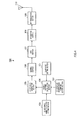
- FIG.4 is a block diagram showing the configuration of a radio communication terminal apparatus (hereinafter, referred to as "terminal") 10 according to Embodiment 1 of the present invention. Next, a configuration of terminal 100 will be explained using FIG.4 .
- CoMP mode setting section 101 sets to hopping pattern calculation section 104 a CoMP mode designated in advance by a radio communication base station apparatus (hereinafter, referred to as "base station"), that is, whether terminal 100 performs CoMP transmission and reception (CoMP terminal), or terminal 100 does not perform CoMP transmission and reception (Non-CoMP terminal).
- base station a radio communication base station apparatus
- ZC sequence number inside CoMP set setting section 102 sets ZC sequence numbers for an SRS assigned to a plurality of cells inside a CoMP set, and outputs the result to hopping pattern calculation section 104.
- ZC sequence number in system setting section 103 sets all ZC sequence numbers for an SRS available in a system, and outputs the result to hopping pattern calculation section 104.
- Hopping pattern calculation section 104 calculates a hopping pattern of ZC sequence numbers according to a CoMP mode set by CoMP mode setting section 101, and outputs ZC sequence numbers to be used at transmission timing to ZC sequence generation section 105, based on the calculated hopping pattern. Specifically, when terminal 100 is a CoMP terminal, a ZC sequence number which is reported from ZC sequence number inside CoMP set setting section 102 and used inside a CoMP set is hopped by the calculated hopping pattern, and therefore a ZC sequence number to be used at transmission timing is calculated.
- terminal 100 is a Non-CoMP terminal
- all ZC sequence numbers reported from ZC sequence number in system setting section 103 and available in the system are hopped by the calculated hopping pattern, a ZC sequence number to be used at transmission timing is calculated. Also, hopping pattern calculation section 104 will be described later in detail.
- ZC sequence generation section 105 generates a ZC sequence to be used as an SRS, by using a ZC sequence number output from hopping pattern calculation section 104, and outputs the result to mapping section 106.
- Mapping section 106 maps a ZC sequence for an SRS output from ZC sequence generation section 105, to a transmission band of terminal 100 designated in advance by a base station, and outputs the mapped ZC sequence to IFFT (Inverse Fast Fourier Transform) section 107.
- IFFT Inverse Fast Fourier Transform
- IFFT section 107 performs IFFT processing on the ZC sequence output from mapping section 106, and outputs the ZC sequence subjected to IFFT processing to CP (Cyclic Prefix) addition section 108.
- CP addition section 108 adds the same signal as the end part of the signal output from IFFT section 107, to the beginning of the signal as a CP, and outputs the signal to RF (radio frequency) transmission section 109.
- RF transmission section 109 performs transmission processing such as D/A conversion, up-conversion and amplification on the signal output from CP addition section 108, and transmits the signal subjected to transmission processing as an SRS via antenna 110.
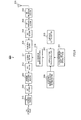
- FIG.5 is a block diagram showing the configuration of base station 200 according to Embodiment 1 of the present invention. The configuration of base station 200 is described below using FIG.5 .
- RF reception section 202 applies reception processing such as down-conversion and A/D conversion to a signal received via antenna 201, and outputs the signal subjected to reception processing is applied to CP removing section 203.
- CP removing section 203 removes the CP added to the top of a reception signal output from RF reception section 202, and outputs the result to FFT (Fast Fourier Transform) section 204.
- FFT Fast Fourier Transform
- FFT section 204 performs FFT processing on an SRS of time domain output from CP removing section 203, transforms the result to frequency domain signals, and outputs the transformed frequency domain to demapping section 205.
- Demapping section 205 extracts an SRS corresponding to a transmission band of a desired terminal from the frequency domain SRS that is output from FFT section 204, and outputs the extracted SRS to division section 211.
- CoMP mode setting section 206 sets to hopping pattern calculation section 209, a CoMP mode designated by a control section (not shown) and the like, that is, whether terminal 100 performs CoMP transmission and reception (CoMP terminal), or terminal 100 does not perform CoMP transmission and reception (Non-CoMP terminal).
- ZC sequence number inside CoMP set setting section 207 sets ZC sequence numbers for an SRS assigned to a plurality of cells inside a CoMP set, and outputs the result to hopping pattern calculation section 209.
- ZC sequence number in system setting section 208 sets all ZC sequence numbers for SRS available in the system, and outputs the result to hopping pattern calculation section 209.
- Hopping pattern calculation section 209 calculates a hopping pattern of ZC sequence numbers according to a CoMP mode set by CoMP mode setting section 206, and outputs ZC sequence numbers to be used at reception timing of a signal transmitted from terminal 100, to ZC sequence generation section 210, based on the calculated hopping pattern. Specifically, when terminal 100 is a CoMP terminal, a ZC sequence number which is reported from ZC sequence number inside CoMP set setting section 207 and to be used inside a CoMP set is hopped by the calculated hopping pattern, and a ZC sequence number to be used at transmission timing is therefore calculated. Meanwhile, when terminal 100 is a Non-CoMP terminal, all ZC sequence numbers which are reported from ZC sequence number in system setting section 208 and available in the system are hopped by the calculated hopping pattern, a ZC sequence number to be used at transmission timing is calculated.
- CoMP mode setting section 206, ZC sequence number inside CoMP set setting section 207, ZC sequence number in system setting section 208, and hopping pattern calculation section 209 correspond to and have the same function as CoMP mode setting section 101, ZC sequence number inside CoMP set setting section 102, ZC sequence number in system setting section 103, and hopping pattern calculation section 104 in terminal 100 shown in FIG.4 respectively.
- hopping pattern calculation section 209 calculates a hopping pattern according to whether terminal 100 transmitting an SRS is a CoMP terminal or a Non-CoMP terminal, and specifies a ZC sequence number at SRS transmission timing of terminal 100.
- ZC sequence generation section 210 generates a ZC sequence for an SRS transmitted by terminal 100, using a ZC sequence number output from hopping pattern calculation section 209, and outputs the result to division section 211.
- Division section 211 divides the SRS output from demapping section 205 by the ZC sequence for an SRS output from ZC sequence generation section 210, and outputs the divided result to IFFT section 212.
- IFFT section 212 performs IFFT processing on the divided result output from division section 211, and outputs the signal subjected to IFFT processing (equivalent to a delay profile) to masking processing section 213.
- Mask processing section 213 extracts the interval in which the correlation value of the desired CS-ZC sequence is present, that is, extracts the correlation value in a CS detection window, by performing mask processing on the SRS output from IFFT section 212, and outputs the extracted correlation value to DFT (Discrete Fourier Transform) section 214.
- DFT Discrete Fourier Transform
- DFT section 214 performs DFT processing to the correlation values output from mask processing section 213 and outputs the correlation values subjected to DFT processing, to CQI estimation section 215.
- the signal which is subjected to DFT processing and output from DFT section 214 represents the frequency response of the channel.
- CQI estimation section 215 estimates (channel quality estimation) SINR for every predetermined bandwidth, based on a signal representing the frequency response output from DFT section 214, and outputs a CQI estimation value corresponding to the estimated SINR.
- hopping pattern calculation section 104 of terminal 100 shown in FIG.4 will be described.
- Hopping pattern calculation section 209 of base station 200 performs the same operation as hopping pattern calculation section 104, and a detailed description therefore will be omitted.
- hopping pattern calculation section 104 switches a hopping pattern of ZC sequence numbers for an SRS, and specifies a ZC sequence number for an SRS, to be used at transmission timing.
- hopping pattern calculation section 104 calculates ZC sequence number u N (t) for an SRS of a Non-CoMP terminal as shown in equation 1, using the hopping function "hopping ( )" which is defined in the system in advance.
- u N t hopping ⁇ u N_init + t
- N represents a cell number
- t represents a transmission subframe number
- u N_init represents an initial value of a ZC sequence number for an SRS in cell N.
- this hopping function changes numbers among all ZC sequence numbers available in the system.
- ZC sequence number u N (t) for an SRS of a Non-CoMP terminal may be fixed without changing by one subframe.
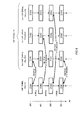
- hopping pattern calculation section 104 hops a ZC sequence number which a Non-CoMP terminal uses inside a CoMP set. For example, when a CoMP set is formed with three cells of cell 1, cell 2, and cell 3, hopping pattern calculation section 104 calculates ZC sequence number u CoMP (t) for an SRS of a CoMP terminal as shown in equation 2.
- u CoMP t u t ⁇ mod 3 + 1 t
- (t)mod(3) represents the number of the remainder calculated by dividing transmission subframe number t by cell number 3.
- transmission subframe number t is changed in order of t#0 ⁇ t#1 ⁇ t#2 ⁇ t#3 ⁇ t#4.
- ZC sequence number u CoMP (t) for an SRS of a CoMP terminal to be used at transmission timing of each transmission subframe is changed as u 1 (0) ⁇ u 2 (1) ⁇ u 3 (2) ⁇ u 1 (3) ⁇ u 2 (4) according to equation 2.
- the change is made among ZC sequence numbers to be used in cells #1, 2, and 3 inside a CoMP set.
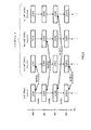
- FIG.6 shows this state.
- ZC sequence number 1 (ZC#1) is assigned to cell 1 inside a CoMP set
- ZC sequence number 2 (ZC#2) is assigned to cell 2
- ZC sequence number 3 (ZC#3) is assigned to cell 3, respectively.
- the ZC sequence number for an SRS of a CoMP terminal the number to be used by transmission subframe number t at transmission timing of t#0, becomes ZC#1, and a CoMP terminal and a Non-CoMP terminal which is in cell 1 multiplex the ZC sequence of ZC#1 by different CSZC sequences.
- the ZC sequence number for an SRS of a CoMP terminal hops from ZC#1 to ZC#2, a CoMP terminal and a Non-CoMP terminal which is in cell 2 multiplex the ZC sequence of ZC#2 by different CSZC sequences.
- the ZC sequence number for an SRS of a CoMP terminal hops from ZC#2 to ZC#3, a CoMP terminal and a Non-CoMP terminal which is in cell 3 multiplex the ZC sequence of ZC#2 by different CSZC sequences.
- the ZC sequence number for an SRS of a CoMP terminal the number to be used by transmission subframe number t at a transmission timing of t#3, hops from ZC#3 to ZC#1, and thereby returns to the case where transmission subframe number t is t#0.
- interference components become cross-correlation at a certain level, and it is therefore possible to reduce deterioration of the accuracy of CQI estimation even if the receiving timing is delayed, as shown in FIG.7 . Also, a certain level of interference components makes it possible to perform compensation calculation at a receiver and thereby to prevent deterioration of the accuracy of CQI estimation.
- a CoMP terminal uses a ZC sequence inside a CoMP set, thereby not providing inter-cell interference to a terminal outside a CoMP set. That is, the distance between cells using the same ZC sequence number can be maintained as designed, so that it is possible to prevent increasing of inter-cell interference between a CoMP terminal and a terminal outside a CoMP set.
- Embodiment 1 by hopping a ZC sequence number used by a CoMP terminal within the range of the ZC sequence to be used inside a CoMP set, it is possible to prevent strong interference occurring when a CoMP terminal and a Non-CoMP terminal use the same ZC sequence, from continuing in one cell. Also, a CoMP terminal uses a ZC sequence inside a CoMP set, it is possible to prevent increasing of inter-cell interference between a CoMP terminal and a terminal outside a CoMP set.
- a ZC sequence number assigned to a cell inside a CoMP set may be hopped, as shown in FIG.9 .
- Hopping patterns of ZC sequence numbers used by a CoMP terminal and a Non-CoMP terminal may not have regularity.
- hopping pattern calculation section 104 Since the configuration of a terminal according to Embodiment 2 of the present invention is similar to the configuration of Embodiment 1 shown in FIG.4 and is different only in function of hopping pattern calculation section 104, so that hopping pattern calculation section 104 will be described using FIG.4 . Also, since the configuration of a base station to Embodiment 2 of the present invention is similar to the configuration of Embodiment 1 shown in FIG.5 , and is different only in function of hopping pattern calculation section 209, which is the same as hopping pattern calculation section 104 of a terminal, a detailed description will be therefore omitted.
- hopping pattern calculation section 104 switches hopping patterns of ZC sequence numbers for an SRS, and specifies the ZC sequence number for an SRS which should be used at transmission timing.
- hopping pattern calculation section 104 calculates ZC sequence number u N (t) for an SRS of a Non-CoMP terminal by equation 1.
- hopping pattern calculation section 104 hops a ZC sequence number to be used by a Non-CoMP terminal outside a CoMP set. For example, when a CoMP set is formed with three cells of cell 1, cell 2, and cell 3, hopping pattern calculation section 104 calculates ZC sequence number u CoMP (t) for an SRS of a CoMP terminal as shown in equation 3.
- u CoMP t u t ⁇ mod 27 + 4 t
- 27 represents the number obtained by subtracting 3 which is the number of cells of a CoMP set, from 30 which is the number of all ZC sequence numbers available in the whole system, that is the number of ZC sequence number to be used outside a CoMP set.
- transmission subframe number t is assumed to be changed in order of t#0 ⁇ t#1 ⁇ t#2 ⁇ t#3 ⁇ t#4.
- ZC sequence number u CoMP (t) for an SRS of a CoMP terminal the number to be used at transmission timing of each transmission subframe becomes u 4 (0) ⁇ u 5 (1) ⁇ u 6 (2) ⁇ u 7 (3) ⁇ u 8 (4), according to equation 3.
- the change is made among ZC sequence numbers used outside a CoMP set.
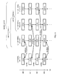
- FIG.10 shows this state.
- a ZC sequence number for an SRS of a CoMP terminal uses ZC#4, ZC sequence number 1 (ZC#1) is assigned to cell 1 inside a CoMP set, ZC sequence number 2 (ZC#2) is assigned to cell 2, and ZC sequence number 3 (ZC#3) is assigned to cell 3, respectively.
- a ZC sequence number for an SRS of a CoMP terminal hops from ZC#4 to ZC#7, cell 1 hops from ZC#1 to ZC#4, cell 2 hops from ZC#2 to ZC#5, and cell 3 hops from ZC#3 to ZC#6.
- a ZC sequence number for an SRS of a CoMP terminal hops from ZC#7 to ZC#10, cell 1 hops from ZC#4 to ZC#7, cell 2 hops from ZC#5 to ZC#8, and cell 3 hops from ZC#6 to ZC#9.
- a ZC sequence number for an SRS of a CoMP terminal hops from ZC#10 to ZC#13, cell 1 hops from ZC#7 to ZC#10, cell 2 hops from ZC#8 to ZC#11, and cell 3 hops from ZC#9 to ZC#12.
- Embodiment 2 by hopping a ZC sequence number used by a CoMP terminal within the range of the ZC sequence to be used outside a CoMP set, a ZC sequence number for an SRS of a CoMP terminal and a ZC sequence number for an SRS of a Non-CoMP terminal always differ inside a CoMP set. Therefore, it is possible to prevent strong interference occurring in the case where a CoMP terminal and a Non-CoMP terminal use the same ZC sequence.
- a Non-CoMP terminal inside a CoMP set hops a ZC sequence number used by a CoMP terminal with a different pattern, and it is therefore possible to randomize interference between a Non-CoMP terminal outside a CoMP set, the Non-CoMP terminal using the same ZC sequence number as that inside a CoMP set and a Non-CoMP terminal inside a CoMP set, and thereby to reduce deterioration of the accuracy of CQI estimation caused by the interference.
- Embodiment 3 of the present invention will describe a case where a certain cell includes a plurality of CoMP terminals and different CoMP sets include a plurality of CoMP terminals.
- a ZC sequence number for an SRS to each CoMP terminal in a cell differs. Therefore, it is not possible to make SRS used by a plurality of CoMP terminals orthogonal by CDM (code domain), and therefore the accuracy of CQI estimation deteriorates.
- SRS orthogonality can prevent deterioration of the accuracy of CQI estimation, but a time for SRS transmission in a cell and overhead of frequency resource increase.
- the configuration of a terminal according to Embodiment 3 of the present invention is similar to the configuration shown in FIG.4 of Embodiment 1 and differs only in function of ZC sequence number inside CoMP set setting section 102, and therefore the different functions thereof will be explained using FIG.4 . Also, since the configuration of a base station to Embodiment 3 of the present invention is similar to the configuration of Embodiment 1 shown in FIG.5 , and differs only in function of ZC sequence number inside CoMP set setting section 207, which is the same as ZC sequence number inside CoMP set setting section 207 of a terminal, a detailed description will be therefore omitted.
- ZC sequence number inside CoMP set setting section 102 sets a ZC sequence number for an SRS, that is, the number to be used by all cells forming a CoMP set where a plurality of CoMP terminals present in a cell belong, and outputs the setting result to hopping pattern calculation section 104.
- ZC sequence number inside CoMP set setting section 102 sets all cells forming CoMP sets where a plurality of CoMP terminals belongs respectively, that is, a combining CoMP set formed by cells 1 to 3. Then, ZC sequence number inside CoMP set setting section 102 outputs ZC sequence numbers for SRSs of cells 1 to 3 to hopping pattern calculation section 104.
- FIG.11 shows this state.
- FIG.11 has the same hopping pattern as shown in FIG.9
- FIG.11 differs from FIG.9 in that two CoMP terminals 1 and 2 use the same ZC sequence.
- Fig.11 differs from FIG.9 in that a CoMP set where CoMP terminal 1 belongs is formed by cells 1 and 2
- a CoMP set where CoMP terminal 2 belongs is formed by cells 2 and 3
- ZC sequence numbers are hopped among all cells forming CoMP sets where a plurality of CoMP terminals belong.
- a ZC sequence number to be used by a CoMP terminal is hopped, within the range of the ZC sequence to be used by all cells forming CoMP sets where a plurality of CoMP terminals belong. Consequently, it is possible to make ZC sequence numbers used by a plurality of CoMP terminals present in a certain cell to be the same, and therefore CDM (code axis) can orthogonalize SRSs used by a plurality of CoMP terminals. Therefore, it is possible to prevent the accuracy of CQI estimation from deterioration. Also, there is no need to multiplex SRSs of a plurality of CoMP terminals in order to be orthogonal by TDM or FDM, so that it is possible to reduce a time for SRS transmission and overhead of frequency resource.
- a CoMP set in the above embodiments can be referred to as "CoMP cooperating set.”
- an SRS transmitted by a terminal to which UL CoMP is applied may be used for CSI (Channel State Information) feedback to perform adaptive control (resource assignment, MCS control, update of a precoding vector) of downlink CoMP in TDD (Time Division Duplex).
- CSI Channel State Information
- MCS Modulation Control
- TDD Time Division Duplex
- ZC sequence number in the above embodiments may be replaced as "ZC sequence group number.”
- each function block employed in the description of each of the aforementioned embodiments may typically be implemented as an LSI constituted by an integrated circuit. These may be individual chips or partially or totally contained on a single chip. "LSI” is adopted here but this may also be referred to as “IC,” “system LSI,” “super LSI,” or “ultra LSI” depending on differing extents of integration.
- circuit integration is not limited to LSI's, and implementation using dedicated circuitry or general purpose processors is also possible.
- FPGA Field Programmable Gate Array
- reconfigurable processor where connections and settings of circuit cells in an LSI can be regenerated is also possible.
- An antenna port refers to a theoretical antenna comprised of one or a plurality of physical antennas.
- an antenna port is not limited to mean one physical antenna, and may be for example an array antenna formed by multiple antennas.
- 3 GPP LTE does not define how many physical antennas an antenna port is formed with, but defines that an antenna port is the minimum unit for transmitting different reference signals in a base station.
- an antenna port may be defined as a minimum unit for multiplying a precoding vector as weighting.
- a radio communication apparatus and reference signal generation method of the present invention are applicable, for example, to a mobile communication system such as an LTE-Advanced system.
Abstract
Description
- The present invention relates to a radio communication apparatus and reference signal generation method that generates a reference signal used to estimate channel quality.
- In an uplink of LTE-Advanced, which is improved 3GPP LTE (3rd Generation Partnership Project Long Term Evolution), a study is underway to introduce UL CoMP (Coordinated multiple point transmission and reception). CoMP is a technique aiming to improve mainly throughput of a terminal located in a cell edge, by performing transmission and reception with a terminal between a plurality of cells (base stations) in a coordinated manner.
- In the case of UL CoMP, by receiving and combining a transmission signal from one terminal at a plurality of cells (base stations), reception quality is improved. At this time, within a group (hereinafter, referred to as "CoMP set") of cells performing transmission and reception in a coordinate manner, terminal scheduling is also performed in a coordinated manner among a plurality of cells forming a CoMP set, in order to reduce influence of inter-cell interference.
- On the other hand, LTE uses an SRS (Sounding Reference Signal) of uplink. Here, "Sounding" is referred to estimating channel quality, and an SRS is transmitted by time-multiplexing a specific symbol with data in order to mainly estimate CQI (Channel Quality Indicator) of uplink data channel.
- LTE uses a ZC (Zadoff-Chu) sequence as an SRS. The characteristic of a ZC sequence includes that CS-ZC (Cyclic Shifted-ZC) sequences generated by cyclically shifting a ZC sequence of any ZC sequence number with a longer time length than the maximum propagation delay time are ideally orthogonal (inter-code interference is zero). However, ZC sequences having different ZC sequence numbers are not orthogonal, and cross-correlation (inter-code interference) occurs at a certain level of "1/ZC sequence length". According to the above characteristic, LTE provides a ZC sequence group defining ZC sequence numbers for each transmission bandwidth available in cells, and one ZC sequence group is assigned to each cell (e.g. see Non-Patent Document 1). 30 of these ZC sequence groups are defined, and to reduce inter-cell interference, different ZC sequence groups are assigned to adjacent cells.
- In order to improve reception quality in the above UL CoMP, accurate estimation of channel quality using an SRS is necessary. Therefore, at first, it is necessary to select a ZC sequence number for an SRS transmitted by a terminal to which UL CoMP is applied, that is, the terminal (hereinafter, referred to as "CoMP terminal") where transmission signals are received and combined at a plurality of cells. As this selection method, two methods (
selection method 1 and selection method 2) can be considered. -
Selection method 1 is a method selecting, for an SRS of a CoMP terminal, a ZC sequence assigned to a cell (hereinafter, referred to as "serving cell") that transmits control information such as scheduling information to the terminal. That is, in a serving cell of a CoMP terminal, a terminal (hereinafter, referred to as "Non-CoMP terminal") to which UL CoMP is not applied uses the same ZC sequence for an SRS as a CoMP terminal. -
Selection method 2 is a method selecting, for an SRS of a CoMP terminal, a ZC sequence of a ZC sequence number different from that of a ZC sequence to be used by a Non-CoMP terminal inside a CoMP set. That is, a ZC sequence belonging to a ZC sequence group (a ZC sequence group not used inside a CoMP set, that is, a ZC sequence group used outside a CoMP set) different from ZC sequence groups assigned to cells inside a CoMP set, is used in an SRS of a CoMP terminal. -
- NPL1
- 3GPP TS36.211 V8.7.0.5.5.1 Generation of the reference signal sequence, "Physical Channels and Modulation (Release 8)"
- However, the
above selection method 1 has a problem that strong interference occurs inside a CoMP set. This problem will be explained below in detail. - As shown in
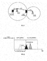
FIG.1 , when a CoMP terminal transmits one transmission signal to a plurality of cells having different distances, each cell receives the signal at different reception timing, thereby making transmission timing control at a terminal complicated. Therefore, in a certain cell, wrong transmission timing control causes reception timing of an SRS transmitted by a CoMP terminal to expand a predetermined time range, which breaks the orthogonality between CS-ZC sequences using the same ZC sequence numbers. - When reception timing of an SRS which a CoMP terminal transmits is delayed by expanding a predetermined time length, a large correlation value of reception SRS of a CoMP terminal expands a predetermined CS (Cyclic Shift) detection window and enters a CS detection window of a Non-CoMP terminal, as shown in correlation output (delay profile) of an SRS in
FIG.2 . - As a result, in a CS detection window of a CoMP terminal, it is not possible to detect reception SRS of a CoMP terminal. A reception SRS correlation value of a CoMP terminal entering a CS detection window of a Non-CoMP terminal becomes a significant interference component, so that in a CS detection window of a Non-CoMP terminal, it is difficult to distinguish between an interference component and a signal component, which deteriorates the accuracy of CQI estimation.
- Further, once reception timing of an SRS that a CoMP terminal transmits is delayed, an SRS of a Non-CoMP terminal is always interfered strongly by CS-ZC sequences having broken orthogonality in a CoMP terminal, until transmission timing control is updated. Therefore, in this cell, the accuracy of CQI estimation is deteriorated, causing adequate scheduling not to perform properly, and thus system throughput is deteriorated.
- In the
above selection method 2, there is a problem that interference increases outside CoMP set. This problem will be explained below in detail. - When a CoMP terminal uses ZC sequence numbers to be used outside a CoMP set, inter-cell interference between a Non-CoMP terminal (a conventional LTE terminal) outside a CoMP set and a CoMP terminal increases, thereby deteriorating the accuracy of CQI estimation. Since the number of ZC sequence numbers (a ZC sequence group) which a terminal can use is limited, when ZC sequence numbers outside a comp set are used, the distance to a Non-CoMP terminal in a cell using the same ZC sequence number becomes short, thereby increasing inter-cell interference (cross-correlation).
FIG.3 shows this state. -
FIG.3 shows ZC sequence numbers used in cells, when ZC sequence numbers available in a system are 1 to 19 for ease of explanation. InFIG.3 , one cell is represented in a hexagon shape and ZC sequence numbers are assigned to make cells using the same ZC sequence number to be as distant as possible from each other, in order to reduce inter-cell interference. As shown inFIG.3 , it is assumed that cells whereZC sequence numbers ZC sequence number 16 not used in the CoMP set as a ZC sequence for an SRS. In this case, since the distance to the cell using theZC sequence number 16 outside a CoMP set becomes shorter, and the distance attenuation of an interference wave becomes smaller, thereby increasing inter-cell interference. - It is therefore an object of the present invention to provide a radio communication apparatus and reference signal generation method that reduce inter-cell interference inside and outside a CoMP set.
- The radio communication apparatus of the present invention employs a configuration having: a CoMP mode setting section that sets one of a CoMP terminal to which CoMP (Coordinated Multiple Point transmission and reception) transmission and reception for performing transmission and reception among a plurality of cells in a coordinated manner, is applied, and a Non-CoMP terminal to which the CoMP transmission and reception is not applied; a hopping pattern calculation section that includes a plurality of different hopping patterns for hopping a ZC (Zadoff-Chu) sequence number to be used for a reference signal, hops the ZC sequence number by a hopping pattern according to the CoMP terminal or the Non-CoMP terminal set by the CoMP mode setting section, and calculates the ZC sequence number; and a ZC sequence generation section that generates a ZC sequence using the calculated ZC sequence number.
- The reference signal generation method of the present invention: sets one of a CoMP terminal to which CoMP (Coordinated Multiple Point transmission and reception) transmission and reception for performing transmission and reception among a plurality of cells in a coordinated manner, is applied, and a Non-CoMP terminal to which the CoMP transmission and reception is not applied; includes a plurality of different hopping patterns for hopping a ZC (Zadoff-Chu) sequence number to be used as a reference signal, hops the ZC sequence number by a hopping pattern according to the set CoMP terminal or the set Non-CoMP terminal, and calculates the ZC sequence number; and generates a ZC sequence to be used for the reference signal, using the calculated ZC sequence number.
- According to the present invention, it is possible to reduce inter-cell interference inside and outside a CoMP set.
-
-
FIG.1 shows that a transmission signal from a CoMP terminal is received at a plurality of cells having different distances; -
FIG.2 shows correlation output of SRSs which a CoMP terminal and a Non-CoMP terminal transmit; -
FIG.3 shows ZC sequence numbers to be used in cells; -
FIG.4 is a block diagram showing a configuration of a radio communication terminal apparatus according toEmbodiment 1 of the present invention; -
FIG.5 is a block diagram showing a configuration of a base station according toEmbodiment 1 of the present invention; -
FIG.6 shows a hopping pattern of ZC sequence numbers according toEmbodiment 1 of the present invention; -
FIG.7 shows correlation output of SRSs transmitted by a CoMP terminal and a Non-CoMP terminal according toEmbodiment 1 of the present invention; -
FIG.8 shows the state able to maintain distances between cells using the same ZC sequence numbers as designed; -
FIG.9 shows other hopping pattern of ZC sequence numbers according toEmbodiment 1 of the present invention; -
FIG.10 shows a hopping pattern of ZC sequence numbers according toEmbodiment 2 of the present invention; and -
FIG.11 shows a hopping pattern of ZC sequence numbers according toEmbodiment 3 of the present invention. - Embodiments of the present invention will be described in detail with reference to the accompanying drawings.
-
FIG.4 is a block diagram showing the configuration of a radio communication terminal apparatus (hereinafter, referred to as "terminal") 10 according toEmbodiment 1 of the present invention. Next, a configuration ofterminal 100 will be explained usingFIG.4 . - CoMP
mode setting section 101 sets to hopping pattern calculation section 104 a CoMP mode designated in advance by a radio communication base station apparatus (hereinafter, referred to as "base station"), that is, whetherterminal 100 performs CoMP transmission and reception (CoMP terminal), orterminal 100 does not perform CoMP transmission and reception (Non-CoMP terminal). - ZC sequence number inside CoMP
set setting section 102 sets ZC sequence numbers for an SRS assigned to a plurality of cells inside a CoMP set, and outputs the result to hoppingpattern calculation section 104. - ZC sequence number in
system setting section 103 sets all ZC sequence numbers for an SRS available in a system, and outputs the result to hoppingpattern calculation section 104. - Hopping
pattern calculation section 104 calculates a hopping pattern of ZC sequence numbers according to a CoMP mode set by CoMPmode setting section 101, and outputs ZC sequence numbers to be used at transmission timing to ZCsequence generation section 105, based on the calculated hopping pattern. Specifically, when terminal 100 is a CoMP terminal, a ZC sequence number which is reported from ZC sequence number inside CoMPset setting section 102 and used inside a CoMP set is hopped by the calculated hopping pattern, and therefore a ZC sequence number to be used at transmission timing is calculated. Meanwhile, when terminal 100 is a Non-CoMP terminal, all ZC sequence numbers reported from ZC sequence number insystem setting section 103 and available in the system are hopped by the calculated hopping pattern, a ZC sequence number to be used at transmission timing is calculated. Also, hoppingpattern calculation section 104 will be described later in detail. - ZC
sequence generation section 105 generates a ZC sequence to be used as an SRS, by using a ZC sequence number output from hoppingpattern calculation section 104, and outputs the result tomapping section 106. -
Mapping section 106 maps a ZC sequence for an SRS output from ZCsequence generation section 105, to a transmission band ofterminal 100 designated in advance by a base station, and outputs the mapped ZC sequence to IFFT (Inverse Fast Fourier Transform)section 107. -
IFFT section 107 performs IFFT processing on the ZC sequence output frommapping section 106, and outputs the ZC sequence subjected to IFFT processing to CP (Cyclic Prefix)addition section 108. -
CP addition section 108 adds the same signal as the end part of the signal output fromIFFT section 107, to the beginning of the signal as a CP, and outputs the signal to RF (radio frequency)transmission section 109. -
RF transmission section 109 performs transmission processing such as D/A conversion, up-conversion and amplification on the signal output fromCP addition section 108, and transmits the signal subjected to transmission processing as an SRS viaantenna 110. -
FIG.5 is a block diagram showing the configuration ofbase station 200 according toEmbodiment 1 of the present invention. The configuration ofbase station 200 is described below usingFIG.5 . -
RF reception section 202 applies reception processing such as down-conversion and A/D conversion to a signal received viaantenna 201, and outputs the signal subjected to reception processing is applied toCP removing section 203. -
CP removing section 203 removes the CP added to the top of a reception signal output fromRF reception section 202, and outputs the result to FFT (Fast Fourier Transform)section 204. -
FFT section 204 performs FFT processing on an SRS of time domain output fromCP removing section 203, transforms the result to frequency domain signals, and outputs the transformed frequency domain todemapping section 205. -
Demapping section 205 extracts an SRS corresponding to a transmission band of a desired terminal from the frequency domain SRS that is output fromFFT section 204, and outputs the extracted SRS todivision section 211. - CoMP
mode setting section 206 sets to hoppingpattern calculation section 209, a CoMP mode designated by a control section (not shown) and the like, that is, whetherterminal 100 performs CoMP transmission and reception (CoMP terminal), orterminal 100 does not perform CoMP transmission and reception (Non-CoMP terminal). - ZC sequence number inside CoMP
set setting section 207 sets ZC sequence numbers for an SRS assigned to a plurality of cells inside a CoMP set, and outputs the result to hoppingpattern calculation section 209. - ZC sequence number in
system setting section 208 sets all ZC sequence numbers for SRS available in the system, and outputs the result to hoppingpattern calculation section 209. - Hopping
pattern calculation section 209 calculates a hopping pattern of ZC sequence numbers according to a CoMP mode set by CoMPmode setting section 206, and outputs ZC sequence numbers to be used at reception timing of a signal transmitted fromterminal 100, to ZCsequence generation section 210, based on the calculated hopping pattern. Specifically, when terminal 100 is a CoMP terminal, a ZC sequence number which is reported from ZC sequence number inside CoMPset setting section 207 and to be used inside a CoMP set is hopped by the calculated hopping pattern, and a ZC sequence number to be used at transmission timing is therefore calculated. Meanwhile, when terminal 100 is a Non-CoMP terminal, all ZC sequence numbers which are reported from ZC sequence number insystem setting section 208 and available in the system are hopped by the calculated hopping pattern, a ZC sequence number to be used at transmission timing is calculated. - CoMP
mode setting section 206, ZC sequence number inside CoMPset setting section 207, ZC sequence number insystem setting section 208, and hoppingpattern calculation section 209 correspond to and have the same function as CoMPmode setting section 101, ZC sequence number inside CoMPset setting section 102, ZC sequence number insystem setting section 103, and hoppingpattern calculation section 104 interminal 100 shown inFIG.4 respectively. - As described above, hopping
pattern calculation section 209 calculates a hopping pattern according to whetherterminal 100 transmitting an SRS is a CoMP terminal or a Non-CoMP terminal, and specifies a ZC sequence number at SRS transmission timing ofterminal 100. - ZC
sequence generation section 210 generates a ZC sequence for an SRS transmitted byterminal 100, using a ZC sequence number output from hoppingpattern calculation section 209, and outputs the result todivision section 211. -
Division section 211 divides the SRS output fromdemapping section 205 by the ZC sequence for an SRS output from ZCsequence generation section 210, and outputs the divided result toIFFT section 212. -
IFFT section 212 performs IFFT processing on the divided result output fromdivision section 211, and outputs the signal subjected to IFFT processing (equivalent to a delay profile) to maskingprocessing section 213. -
Mask processing section 213 extracts the interval in which the correlation value of the desired CS-ZC sequence is present, that is, extracts the correlation value in a CS detection window, by performing mask processing on the SRS output fromIFFT section 212, and outputs the extracted correlation value to DFT (Discrete Fourier Transform)section 214. -
DFT section 214 performs DFT processing to the correlation values output frommask processing section 213 and outputs the correlation values subjected to DFT processing, toCQI estimation section 215. Here, the signal which is subjected to DFT processing and output fromDFT section 214 represents the frequency response of the channel. -
CQI estimation section 215 estimates (channel quality estimation) SINR for every predetermined bandwidth, based on a signal representing the frequency response output fromDFT section 214, and outputs a CQI estimation value corresponding to the estimated SINR. - Next, the operation of hopping
pattern calculation section 104 ofterminal 100 shown inFIG.4 will be described. Hoppingpattern calculation section 209 ofbase station 200 performs the same operation as hoppingpattern calculation section 104, and a detailed description therefore will be omitted. - According to whether
terminal 100 is a CoMP terminal or a Non-CoMP terminal, hoppingpattern calculation section 104 switches a hopping pattern of ZC sequence numbers for an SRS, and specifies a ZC sequence number for an SRS, to be used at transmission timing. - First, when terminal 100 is a Non-CoMP terminal, hopping
pattern calculation section 104 calculates ZC sequence number uN(t) for an SRS of a Non-CoMP terminal as shown inequation 1, using the hopping function "hopping ( )" which is defined in the system in advance.
- Here, N represents a cell number, t represents a transmission subframe number, and uN_init represents an initial value of a ZC sequence number for an SRS in cell N. By each subframe, this hopping function changes numbers among all ZC sequence numbers available in the system. However, ZC sequence number uN(t) for an SRS of a Non-CoMP terminal may be fixed without changing by one subframe.
- Next, when terminal 100 is a CoMP terminal, hopping
pattern calculation section 104 hops a ZC sequence number which a Non-CoMP terminal uses inside a CoMP set. For example, when a CoMP set is formed with three cells ofcell 1,cell 2, andcell 3, hoppingpattern calculation section 104 calculates ZC sequence number uCoMP(t) for an SRS of a CoMP terminal as shown inequation 2.
- In
equation 2, (t)mod(3) represents the number of the remainder calculated by dividing transmission subframe number t bycell number 3. Here, it is assumed that transmission subframe number t is changed in order oft# 0→t# 1→t# 2→t# 3→t# 4. In this case, ZC sequence number uCoMP(t) for an SRS of a CoMP terminal to be used at transmission timing of each transmission subframe is changed as u1(0)→u2(1)→u3(2)→u1(3)→u2(4) according toequation 2. The change is made among ZC sequence numbers to be used incells # -
FIG.6 shows this state. InFIG.6 , ZC sequence number 1 (ZC#1) is assigned tocell 1 inside a CoMP set, ZC sequence number 2 (ZC#2) is assigned tocell 2, and ZC sequence number 3 (ZC#3) is assigned tocell 3, respectively. The ZC sequence number for an SRS of a CoMP terminal, the number to be used by transmission subframe number t at transmission timing oft# 0, becomesZC# 1, and a CoMP terminal and a Non-CoMP terminal which is incell 1 multiplex the ZC sequence ofZC# 1 by different CSZC sequences. - Next, the ZC sequence number for an SRS of a CoMP terminal, the number to be used by transmission subframe number t at transmission timing of
t# 1, hops fromZC# 1 toZC# 2, a CoMP terminal and a Non-CoMP terminal which is incell 2 multiplex the ZC sequence ofZC# 2 by different CSZC sequences. - Next, the ZC sequence number for an SRS of a CoMP terminal, the number to be used by transmission subframe number t at transmission timing of
t# 2, hops fromZC# 2 toZC# 3, a CoMP terminal and a Non-CoMP terminal which is incell 3 multiplex the ZC sequence ofZC# 2 by different CSZC sequences. - The ZC sequence number for an SRS of a CoMP terminal, the number to be used by transmission subframe number t at a transmission timing of
t# 3, hops fromZC# 3 toZC# 1, and thereby returns to the case where transmission subframe number t ist# 0. - By hopping ZC sequence numbers used by a CoMP terminal within the range of the ZC sequence to be used inside a CoMP set, it is possible to prevent strong interference occurring when a CoMP terminal and a Non-CoMP terminal use the same ZC sequence from continuing in one cell. This is contributed by hopping ZC sequence numbers that a CoMP terminal uses and ZC sequence numbers that a Non-CoMP terminal using different hopping patterns, and by making a switching interval of ZC sequences according to hopping shorter than an updating interval of transmission timing control.
- When a CoMP terminal and a Non-CoMP terminal use different ZC sequence numbers, interference components become cross-correlation at a certain level, and it is therefore possible to reduce deterioration of the accuracy of CQI estimation even if the receiving timing is delayed, as shown in
FIG.7 . Also, a certain level of interference components makes it possible to perform compensation calculation at a receiver and thereby to prevent deterioration of the accuracy of CQI estimation. - As shown in
FIG.8 , a CoMP terminal uses a ZC sequence inside a CoMP set, thereby not providing inter-cell interference to a terminal outside a CoMP set. That is, the distance between cells using the same ZC sequence number can be maintained as designed, so that it is possible to prevent increasing of inter-cell interference between a CoMP terminal and a terminal outside a CoMP set. - Thus, according to
Embodiment 1, by hopping a ZC sequence number used by a CoMP terminal within the range of the ZC sequence to be used inside a CoMP set, it is possible to prevent strong interference occurring when a CoMP terminal and a Non-CoMP terminal use the same ZC sequence, from continuing in one cell. Also, a CoMP terminal uses a ZC sequence inside a CoMP set, it is possible to prevent increasing of inter-cell interference between a CoMP terminal and a terminal outside a CoMP set. - Although the present embodiment has described a case where a ZC sequence assigned to a cell inside a CoMP set is fixed, a ZC sequence number assigned to a cell inside a CoMP set may be hopped, as shown in
FIG.9 . However, in this case, it is necessary to make a hopping pattern of a ZC sequence number in a specific cell, different from a hopping pattern of a ZC sequence number used by a CoMP terminal. - By defining in advance a hopping pattern of a ZC sequence number for an SRS, the number used by a CoMP terminal, it is possible to reduce the signaling amount from a base station to a terminal. That is, an initial value (=uN_init) of each cell inside a CoMP set, and a hopping pattern of each cell (for example, in ascending cell number order) need to be reported to a terminal only once, and therefore signaling for each SRS transmission is not necessary.
- Hopping patterns of ZC sequence numbers used by a CoMP terminal and a Non-CoMP terminal may not have regularity.
- Since the configuration of a terminal according to
Embodiment 2 of the present invention is similar to the configuration ofEmbodiment 1 shown inFIG.4 and is different only in function of hoppingpattern calculation section 104, so that hoppingpattern calculation section 104 will be described usingFIG.4 . Also, since the configuration of a base station toEmbodiment 2 of the present invention is similar to the configuration ofEmbodiment 1 shown inFIG.5 , and is different only in function of hoppingpattern calculation section 209, which is the same as hoppingpattern calculation section 104 of a terminal, a detailed description will be therefore omitted. - According to whether
terminal 100 is a CoMP terminal or a Non-CoMP terminal, hoppingpattern calculation section 104 switches hopping patterns of ZC sequence numbers for an SRS, and specifies the ZC sequence number for an SRS which should be used at transmission timing. - When terminal 100 is a Non-CoMP terminal, as in
Embodiment 1, hoppingpattern calculation section 104 calculates ZC sequence number uN(t) for an SRS of a Non-CoMP terminal byequation 1. - Meanwhile, when terminal 100 is a CoMP terminal, hopping
pattern calculation section 104 hops a ZC sequence number to be used by a Non-CoMP terminal outside a CoMP set. For example, when a CoMP set is formed with three cells ofcell 1,cell 2, andcell 3, hoppingpattern calculation section 104 calculates ZC sequence number uCoMP(t) for an SRS of a CoMP terminal as shown inequation 3.
- In
equation 3, 27 represents the number obtained by subtracting 3 which is the number of cells of a CoMP set, from 30 which is the number of all ZC sequence numbers available in the whole system, that is the number of ZC sequence number to be used outside a CoMP set. Here, transmission subframe number t is assumed to be changed in order oft# 0→t# 1→t# 2→t# 3→t# 4. In this case, ZC sequence number uCoMP(t) for an SRS of a CoMP terminal, the number to be used at transmission timing of each transmission subframe becomes u4(0)→u5(1)→u6(2)→u7(3)→u8(4), according toequation 3. The change is made among ZC sequence numbers used outside a CoMP set. -
FIG.10 shows this state. InFIG.10 , at transmission timing when transmission subframe number t ist# 0, a ZC sequence number for an SRS of a CoMP terminal usesZC# 4, ZC sequence number 1 (ZC#1) is assigned tocell 1 inside a CoMP set, ZC sequence number 2 (ZC#2) is assigned tocell 2, and ZC sequence number 3 (ZC#3) is assigned tocell 3, respectively. - Next, at transmission timing when transmission subframe number t changes from
t# 0 tot# 1, a ZC sequence number for an SRS of a CoMP terminal hops fromZC# 4 toZC# 7,cell 1 hops fromZC# 1 toZC# 4,cell 2 hops fromZC# 2 toZC# 5, andcell 3 hops fromZC# 3 toZC# 6. - Next, at transmission timing when transmission subframe number t changes from
t# 1 tot# 2, a ZC sequence number for an SRS of a CoMP terminal hops fromZC# 7 toZC# 10,cell 1 hops fromZC# 4 toZC# 7,cell 2 hops fromZC# 5 toZC# 8, andcell 3 hops fromZC# 6 toZC# 9. - Next, at transmission timing when transmission subframe number t changes from
t# 2 tot# 3, a ZC sequence number for an SRS of a CoMP terminal hops fromZC# 10 toZC# 13,cell 1 hops fromZC# 7 toZC# 10,cell 2 hops fromZC# 8 toZC# 11, andcell 3 hops fromZC# 9 toZC# 12. - Thus, according to
Embodiment 2, by hopping a ZC sequence number used by a CoMP terminal within the range of the ZC sequence to be used outside a CoMP set, a ZC sequence number for an SRS of a CoMP terminal and a ZC sequence number for an SRS of a Non-CoMP terminal always differ inside a CoMP set. Therefore, it is possible to prevent strong interference occurring in the case where a CoMP terminal and a Non-CoMP terminal use the same ZC sequence. - Also, a Non-CoMP terminal inside a CoMP set hops a ZC sequence number used by a CoMP terminal with a different pattern, and it is therefore possible to randomize interference between a Non-CoMP terminal outside a CoMP set, the Non-CoMP terminal using the same ZC sequence number as that inside a CoMP set and a Non-CoMP terminal inside a CoMP set, and thereby to reduce deterioration of the accuracy of CQI estimation caused by the interference.
- Although the present embodiment has described a case where hopping patterns of ZC sequence numbers used by a CoMP terminal and a Non-CoMP terminal has regularity, these hopping patterns need not to have regularity.
-
Embodiment 3 of the present invention will describe a case where a certain cell includes a plurality of CoMP terminals and different CoMP sets include a plurality of CoMP terminals. In this case, by providing a hopping pattern of a ZC sequence number for an SRS to each CoMP terminal, a ZC sequence number for an SRS to each CoMP terminal in a cell differs. Therefore, it is not possible to make SRS used by a plurality of CoMP terminals orthogonal by CDM (code domain), and therefore the accuracy of CQI estimation deteriorates. By multiplexing SRSs for a plurality of CoMP terminals using TDM (time domain) or FDM (frequency domain), SRS orthogonality can prevent deterioration of the accuracy of CQI estimation, but a time for SRS transmission in a cell and overhead of frequency resource increase. - Hereinafter, in the case where a plurality of CoMP terminals are included in different CoMP sets, a method will be described to prevent deterioration of the accuracy of CQI estimation and reduce a time for SRS transmission in a cell and overhead of frequency resource.
- The configuration of a terminal according to
Embodiment 3 of the present invention is similar to the configuration shown inFIG.4 ofEmbodiment 1 and differs only in function of ZC sequence number inside CoMPset setting section 102, and therefore the different functions thereof will be explained usingFIG.4 . Also, since the configuration of a base station toEmbodiment 3 of the present invention is similar to the configuration ofEmbodiment 1 shown inFIG.5 , and differs only in function of ZC sequence number inside CoMPset setting section 207, which is the same as ZC sequence number inside CoMPset setting section 207 of a terminal, a detailed description will be therefore omitted. - ZC sequence number inside CoMP
set setting section 102 sets a ZC sequence number for an SRS, that is, the number to be used by all cells forming a CoMP set where a plurality of CoMP terminals present in a cell belong, and outputs the setting result to hoppingpattern calculation section 104. - For example, it is assumed that two
CoMP terminals CoMP terminal 1 belongs is formed bycells CoMP terminal 2 belongs is formed bycells CoMP terminals set setting section 102 sets all cells forming CoMP sets where a plurality of CoMP terminals belongs respectively, that is, a combining CoMP set formed bycells 1 to 3. Then, ZC sequence number inside CoMPset setting section 102 outputs ZC sequence numbers for SRSs ofcells 1 to 3 to hoppingpattern calculation section 104. -
FIG.11 shows this state. AlthoughFIG.11 has the same hopping pattern as shown inFIG.9 ,FIG.11 differs fromFIG.9 in that twoCoMP terminals Fig.11 differs fromFIG.9 in that a CoMP set whereCoMP terminal 1 belongs is formed bycells CoMP terminal 2 belongs is formed bycells - Thus, according to
Embodiment 3, in the case where a plurality of CoMP terminals present in a certain cell are included in different CoMP sets respectively, a ZC sequence number to be used by a CoMP terminal is hopped, within the range of the ZC sequence to be used by all cells forming CoMP sets where a plurality of CoMP terminals belong. Consequently, it is possible to make ZC sequence numbers used by a plurality of CoMP terminals present in a certain cell to be the same, and therefore CDM (code axis) can orthogonalize SRSs used by a plurality of CoMP terminals. Therefore, it is possible to prevent the accuracy of CQI estimation from deterioration. Also, there is no need to multiplex SRSs of a plurality of CoMP terminals in order to be orthogonal by TDM or FDM, so that it is possible to reduce a time for SRS transmission and overhead of frequency resource. - A CoMP set in the above embodiments can be referred to as "CoMP cooperating set." Also, a CoMP set may be a cell group (=CoMP measurement set) to which a terminal reports channel quality information for CoMP transmission and reception.
- Although the above embodiments have described as an example an SRS transmitted by a terminal to which UL CoMP is applied, the present invention is not limited to this. For example, an SRS may be used for CSI (Channel State Information) feedback to perform adaptive control (resource assignment, MCS control, update of a precoding vector) of downlink CoMP in TDD (Time Division Duplex). Thus, the essential requirement is that one terminal transmits an SRS to a plurality of cells at the same time.
- A ZC sequence number in the above embodiments may be replaced as "ZC sequence group number."
- Although the above embodiments have described a case where a ZC sequence number of a CoMP terminal and a ZC sequence number of a Non-CoMP terminal are hopped at the same switching period, it is equally possible to hop such ZC sequences numbers at different switching periods. For example, it is assumed that a ZC sequence switching period of a Non-CoMP terminal is T1[ms] and a ZC sequence switching period of a CoMP terminal is T2[ms] (please note that T2[ms]>T1[ms], including that T2 is infinite (that is, no switching)).
- By this means, inside a CoMP set, it is possible to prevent strong interference occurring when a CoMP terminal and a Non-CoMP terminal use the same ZC sequence from continuing in one cell. Here, when a switching period of a ZC sequence of one terminal is infinite, only a ZC sequence of the other terminal is switched, and therefore interference with a Non-CoMP terminal outside a CoMP set using the same ZC sequence number can be randomized.
- Although the above embodiments have described an example where the present invention is implemented with hardware, the present invention can be implemented with software.
- Furthermore, each function block employed in the description of each of the aforementioned embodiments may typically be implemented as an LSI constituted by an integrated circuit. These may be individual chips or partially or totally contained on a single chip. "LSI" is adopted here but this may also be referred to as "IC," "system LSI," "super LSI," or "ultra LSI" depending on differing extents of integration.
- Further, the method of circuit integration is not limited to LSI's, and implementation using dedicated circuitry or general purpose processors is also possible. After LSI manufacture, utilization of an FPGA (Field Programmable Gate Array) or a reconfigurable processor where connections and settings of circuit cells in an LSI can be regenerated is also possible.
- Further, if integrated circuit technology comes out to replace LSI's as a result of the advancement of semiconductor technology or a derivative other technology, it is naturally also possible to carry out function block integration using this technology. Application of biotechnology is also possible.
- Although the present invention has been described above with embodiments using antennas, the present invention is equally applicable to antenna ports.
- An antenna port refers to a theoretical antenna comprised of one or a plurality of physical antennas. Thus, an antenna port is not limited to mean one physical antenna, and may be for example an array antenna formed by multiple antennas.
- For example, 3 GPP LTE does not define how many physical antennas an antenna port is formed with, but defines that an antenna port is the minimum unit for transmitting different reference signals in a base station.
- In addition, an antenna port may be defined as a minimum unit for multiplying a precoding vector as weighting.
- The disclosure of Japanese Patent Application No.
2009-250432, filed on October 30, 2009 - A radio communication apparatus and reference signal generation method of the present invention are applicable, for example, to a mobile communication system such as an LTE-Advanced system.
-
- 101, 206
- CoMP mode setting section
- 102, 207
- ZC sequence number inside CoMP set setting section
- 103, 208
- ZC sequence number in system setting section
- 104, 209
- Hopping pattern calculation section
- 105, 210
- ZC sequence generation section
- 106
- Mapping section
- 107, 212
- IFFT section
- 108
- CP addition section
- 109
- RF transmission section
- 110, 210
- Antenna
- 202
- RF reception section
- 203
- CP removing section
- 204
- FFT section
- 205
- Demapping section
- 211
- Division section
- 213
- Masking processing section
- 214
- DFT section
- 215
- CQI estimation section
Claims (6)
- A radio communication apparatus comprising:a CoMP mode setting section configured to set one of a CoMP (Coordinated Multiple Point transmission and reception) terminal to which a CoMP for performing transmission and reception among a plurality of cells in a coordinated manner, is applied, and a Non-CoMP terminal to which the CoMP is not applied;a hopping pattern calculation section configured to include a plurality of different hopping patterns for hopping a ZC (Zadoff-Chu) sequence number used for a reference signal, and calculates the ZC sequence number by hopping the ZC sequence number with a hopping pattern according to the CoMP terminal or the Non-CoMP terminal set by the CoMP mode setting section; anda ZC sequence generation section that generates a ZC sequence using the calculated ZC sequence number.
- The radio communication apparatus according to claim 1, wherein the hopping pattern calculation section calculates the ZC sequence number by hopping the ZC sequence number used inside a CoMP set grouping the plurality of cells for performing transmission and reception in a coordinated manner, when the radio communication apparatus is set as the CoMP terminal by the CoMP mode setting section.
- The radio communication apparatus according to claim 1, wherein the hopping pattern calculation section calculates the ZC sequence number by hopping the ZC sequence number used outside a CoMP set grouping the plurality of cells for performing transmission and reception in a coordinated manner, when the radio communication apparatus is set as the CoMP terminal by the CoMP mode setting section.
- The radio communication apparatus according to claim 2, wherein the CoMP set is configured by all cells configuring CoMP sets to which the plurality of CoMP terminals present in cells belong.
- The radio communication apparatus according to claim 3, wherein the CoMP set is configured by all cells configuring a set of CoMP to which the plurality of CoMP terminals present in a cell belong.
- A reference signal generation method comprising:setting one of a CoMP (Coordinated Multiple Point transmission and reception) terminal to which a CoMP for performing transmission and reception among a plurality of cells in a coordinated manner, is applied, and a Non-CoMP terminal to which the CoMP is not applied;including a plurality of different hopping patterns for hopping a ZC (Zadoff-Chu) sequence number used as a reference signal, calculating the ZC sequence number by hopping the ZC sequence number with a hopping pattern according to the set CoMP terminal or the set Non-CoMP terminal; andgenerating a ZC sequence used for the reference signal using the calculated ZC sequence number.
Priority Applications (8)
| Application Number | Priority Date | Filing Date | Title |
|---|---|---|---|
| PL18155351T PL3337217T3 (en) | 2009-10-30 | 2010-10-29 | Wireless communication apparatus and reference signal generating method |
| EP19173247.8A EP3541109B1 (en) | 2009-10-30 | 2010-10-29 | Wireless communication apparatus and reference signal generating method |
| SI201031742T SI2496005T1 (en) | 2009-10-30 | 2010-10-29 | Wireless communication apparatus and reference signal generating method |
| PL19173247T PL3541109T3 (en) | 2009-10-30 | 2010-10-29 | Wireless communication apparatus and reference signal generating method |
| EP18155351.2A EP3337217B1 (en) | 2009-10-30 | 2010-10-29 | Wireless communication apparatus and reference signal generating method |
| RS20181030A RS57614B1 (en) | 2009-10-30 | 2010-10-29 | Wireless communication apparatus and reference signal generating method |
| PL10826358T PL2496005T3 (en) | 2009-10-30 | 2010-10-29 | Wireless communication apparatus and reference signal generating method |
| HRP20181417TT HRP20181417T1 (en) | 2009-10-30 | 2018-09-05 | Wireless communication apparatus and reference signal generating method |
Applications Claiming Priority (2)
| Application Number | Priority Date | Filing Date | Title |
|---|---|---|---|
| JP2009250432 | 2009-10-30 | ||
| PCT/JP2010/006398 WO2011052222A1 (en) | 2009-10-30 | 2010-10-29 | Wireless communication apparatus and reference signal generating method |
Related Child Applications (3)
| Application Number | Title | Priority Date | Filing Date |
|---|---|---|---|
| EP18155351.2A Division EP3337217B1 (en) | 2009-10-30 | 2010-10-29 | Wireless communication apparatus and reference signal generating method |
| EP18155351.2A Division-Into EP3337217B1 (en) | 2009-10-30 | 2010-10-29 | Wireless communication apparatus and reference signal generating method |
| EP19173247.8A Division EP3541109B1 (en) | 2009-10-30 | 2010-10-29 | Wireless communication apparatus and reference signal generating method |
Publications (3)
| Publication Number | Publication Date |
|---|---|
| EP2496005A1 true EP2496005A1 (en) | 2012-09-05 |
| EP2496005A4 EP2496005A4 (en) | 2017-03-22 |
| EP2496005B1 EP2496005B1 (en) | 2018-06-06 |
Family
ID=43921655
Family Applications (3)
| Application Number | Title | Priority Date | Filing Date |
|---|---|---|---|
| EP19173247.8A Active EP3541109B1 (en) | 2009-10-30 | 2010-10-29 | Wireless communication apparatus and reference signal generating method |
| EP10826358.3A Active EP2496005B1 (en) | 2009-10-30 | 2010-10-29 | Wireless communication apparatus and reference signal generating method |
| EP18155351.2A Active EP3337217B1 (en) | 2009-10-30 | 2010-10-29 | Wireless communication apparatus and reference signal generating method |
Family Applications Before (1)
| Application Number | Title | Priority Date | Filing Date |
|---|---|---|---|
| EP19173247.8A Active EP3541109B1 (en) | 2009-10-30 | 2010-10-29 | Wireless communication apparatus and reference signal generating method |
Family Applications After (1)
| Application Number | Title | Priority Date | Filing Date |
|---|---|---|---|
| EP18155351.2A Active EP3337217B1 (en) | 2009-10-30 | 2010-10-29 | Wireless communication apparatus and reference signal generating method |
Country Status (15)
| Country | Link |
|---|---|
| US (8) | US8797986B2 (en) |
| EP (3) | EP3541109B1 (en) |
| JP (4) | JP5574449B2 (en) |
| KR (1) | KR101580010B1 (en) |
| CY (1) | CY1120973T1 (en) |
| DK (1) | DK2496005T3 (en) |
| ES (3) | ES2685510T3 (en) |
| HR (1) | HRP20181417T1 (en) |
| HU (1) | HUE039041T2 (en) |
| LT (1) | LT2496005T (en) |
| PL (3) | PL3337217T3 (en) |
| PT (1) | PT2496005T (en) |
| RS (1) | RS57614B1 (en) |
| SI (1) | SI2496005T1 (en) |
| WO (1) | WO2011052222A1 (en) |
Cited By (1)
| Publication number | Priority date | Publication date | Assignee | Title |
|---|---|---|---|---|
| CN105122679A (en) * | 2013-04-15 | 2015-12-02 | Lg电子株式会社 | Methods and devices for transmitting sounding reference signal in wireless access system |
Families Citing this family (12)
| Publication number | Priority date | Publication date | Assignee | Title |
|---|---|---|---|---|
| EP3541109B1 (en) * | 2009-10-30 | 2020-07-29 | Sun Patent Trust | Wireless communication apparatus and reference signal generating method |
| KR20160023910A (en) * | 2011-04-29 | 2016-03-03 | 노키아 솔루션스 앤드 네트웍스 오와이 | Method and device for processing uplink control data in a wireless network |
| KR20130011441A (en) * | 2011-07-21 | 2013-01-30 | 주식회사 팬택 | Method and apparatus for transmitting control information |
| WO2013025136A1 (en) * | 2011-08-15 | 2013-02-21 | Telefonaktiebolaget L M Ericsson (Publ) | Femtocell base station, method, computer program and computer program product |
| DE102011118076B4 (en) * | 2011-11-04 | 2024-04-18 | Airbus Operations Gmbh | Methods to significantly increase the availability of wireless connections |
| US9813263B2 (en) | 2012-03-09 | 2017-11-07 | Panasonic Intellectual Property Group of America | Terminal device, wireless transmission method, base station device, and channel estimation method |
| WO2014019170A1 (en) * | 2012-08-01 | 2014-02-06 | Nec(China) Co., Ltd. | Method and apparatus for obtaining channel quality indication |
| CN103581944B (en) | 2012-08-07 | 2016-12-07 | 华为技术有限公司 | Ultrahigh speed random access processing method, Apparatus and system |
| US10531512B2 (en) * | 2015-04-01 | 2020-01-07 | Huawei Technologies Co., Ltd. | System and method for a tracking channel |
| CN106470096B (en) * | 2015-08-14 | 2021-03-23 | 索尼公司 | Apparatus and method for base station side and user equipment side for wireless communication |
| CN113746612B (en) * | 2017-06-15 | 2023-03-24 | 中兴通讯股份有限公司 | Method for generating reference signal, wireless communication device, and storage medium |
| DE102017211375B3 (en) * | 2017-07-04 | 2018-12-13 | Fraunhofer-Gesellschaft zur Förderung der angewandten Forschung e.V. | Specific hopping patterns for repeatedly transmitting and receiving data and methods for generating the same |
Family Cites Families (28)
| Publication number | Priority date | Publication date | Assignee | Title |
|---|---|---|---|---|
| EP1692619B1 (en) * | 2003-11-07 | 2013-01-09 | Sharp Kabushiki Kaisha | Methods and systems for network coordination |
| US8098745B2 (en) * | 2006-03-27 | 2012-01-17 | Texas Instruments Incorporated | Random access structure for wireless networks |
| US8738056B2 (en) * | 2006-05-22 | 2014-05-27 | Qualcomm Incorporation | Signal acquisition in a wireless communication system |
| JP4940867B2 (en) * | 2006-09-29 | 2012-05-30 | 日本電気株式会社 | Multiplexing method of control signal and reference signal, resource allocation method and base station in mobile communication system |
| US7957759B2 (en) * | 2006-12-08 | 2011-06-07 | Texas Instruments Incorporated | Wideband reference signal transmission in SC-FDMA communication systems |
| JP5078989B2 (en) * | 2007-03-15 | 2012-11-21 | パナソニック株式会社 | Wireless transmission apparatus and wireless transmission method |
| JP4601637B2 (en) * | 2007-03-20 | 2010-12-22 | 株式会社エヌ・ティ・ティ・ドコモ | Mobile station, transmission method, and wireless communication system |
| US8676223B2 (en) * | 2007-03-23 | 2014-03-18 | Qualcomm Incorporated | Backhaul communication for interference management |
| CA2684364C (en) * | 2007-04-30 | 2014-02-04 | Nokia Siemens Networks Oy | Coordinated cyclic shift and sequence hopping for zadoff-chu, modified zadoff-chu, and block-wise spreading sequences |
| WO2008155907A1 (en) * | 2007-06-19 | 2008-12-24 | Panasonic Corporation | Sequence allocating method and wireless mobile station device |
| US20100272022A1 (en) * | 2007-12-27 | 2010-10-28 | Panasonic Corporation | Sequence hopping method, wireless communication terminal apparatus and wireless communication base station apparatus |
| JP4724731B2 (en) | 2008-04-11 | 2011-07-13 | 日本ピラー工業株式会社 | Mechanical seal and mechanical seal device |
| EP2301181A1 (en) * | 2008-05-09 | 2011-03-30 | Nokia Siemens Networks OY | Multi-cell channel estimation in 3g-lte based virtual pilot sequences |
| US8942165B2 (en) * | 2008-08-01 | 2015-01-27 | Qualcomm Incorporated | System and method for distributed multiple-input multiple-output (MIMO) in a wireless communication system |
| US8687545B2 (en) * | 2008-08-11 | 2014-04-01 | Qualcomm Incorporated | Anchor carrier in a multiple carrier wireless communication system |
| US9019903B2 (en) * | 2008-12-08 | 2015-04-28 | Qualcomm Incorporated | Optimization to support uplink coordinated multi-point |
| US9425916B2 (en) * | 2008-12-10 | 2016-08-23 | Sun Patent Trust | Wireless communication terminal apparatus, wireless communication base station apparatus and signal spreading method |
| US8442566B2 (en) * | 2009-01-07 | 2013-05-14 | Samsung Electronics Co., Ltd. | Coordinated multipoint (CoMP) joint transmission using channel information feedback and higher rank dedicated beam-forming |
| US20100232336A1 (en) * | 2009-03-13 | 2010-09-16 | Sharp Laboratories Of America, Inc. | Systems and methods for selecting antennas for coordinated multipoint transmission |
| US8693429B2 (en) * | 2009-03-31 | 2014-04-08 | Qualcomm Incorporated | Methods and apparatus for generation and use of reference signals in a communications system |
| US8145223B2 (en) * | 2009-04-09 | 2012-03-27 | Telefonaktiebolaget L M Ericsson (Publ) | Inter-cell interference mitigation |
| EP2425574B1 (en) * | 2009-04-27 | 2013-11-06 | Nokia Siemens Networks Oy | Demodulation reference signals in a communication system |
| US8442545B2 (en) * | 2009-06-17 | 2013-05-14 | Telefonaktiebolaget L M Ericsson (Publ) | Network-wide inter-cell interference minimization via coordinated multipoint cell scheduling coordination |
| EP2457342A1 (en) * | 2009-07-22 | 2012-05-30 | Nokia Siemens Networks OY | Method of coordinating the transmission resources in a coordinated multipoint transmission/receiving communication network |
| PL2894795T3 (en) * | 2009-08-14 | 2018-03-30 | Hmd Global Oy | Improvements for coordinated multipoint transmission |
| US20110244877A1 (en) * | 2009-10-08 | 2011-10-06 | Qualcomm Incorporated | Method and apparatus for using channel state information reference signal in wireless communication system |
| US9031008B2 (en) * | 2009-10-30 | 2015-05-12 | Samsung Electronics Co., Ltd. | Methods and apparatus for multi-user MIMO transmissions in wireless communication systems |
| EP3541109B1 (en) * | 2009-10-30 | 2020-07-29 | Sun Patent Trust | Wireless communication apparatus and reference signal generating method |
-
2010
- 2010-10-29 EP EP19173247.8A patent/EP3541109B1/en active Active
- 2010-10-29 LT LTEP10826358.3T patent/LT2496005T/en unknown
- 2010-10-29 DK DK10826358.3T patent/DK2496005T3/en active
- 2010-10-29 PT PT10826358T patent/PT2496005T/en unknown
- 2010-10-29 KR KR1020127009546A patent/KR101580010B1/en active IP Right Grant
- 2010-10-29 PL PL18155351T patent/PL3337217T3/en unknown
- 2010-10-29 HU HUE10826358A patent/HUE039041T2/en unknown
- 2010-10-29 US US13/501,914 patent/US8797986B2/en active Active
- 2010-10-29 PL PL10826358T patent/PL2496005T3/en unknown
- 2010-10-29 ES ES10826358.3T patent/ES2685510T3/en active Active
- 2010-10-29 EP EP10826358.3A patent/EP2496005B1/en active Active
- 2010-10-29 SI SI201031742T patent/SI2496005T1/en unknown
- 2010-10-29 ES ES18155351T patent/ES2748499T3/en active Active
- 2010-10-29 RS RS20181030A patent/RS57614B1/en unknown
- 2010-10-29 EP EP18155351.2A patent/EP3337217B1/en active Active
- 2010-10-29 WO PCT/JP2010/006398 patent/WO2011052222A1/en active Application Filing
- 2010-10-29 ES ES19173247T patent/ES2822294T3/en active Active
- 2010-10-29 PL PL19173247T patent/PL3541109T3/en unknown
- 2010-10-29 JP JP2011538265A patent/JP5574449B2/en active Active
-
2014
- 2014-06-03 US US14/294,762 patent/US9048972B2/en active Active
- 2014-06-25 JP JP2014130310A patent/JP5788568B2/en active Active
-
2015
- 2015-04-21 US US14/692,391 patent/US9363031B2/en active Active
- 2015-07-28 JP JP2015148418A patent/JP6065071B2/en active Active
-
2016
- 2016-05-03 US US15/144,904 patent/US9893830B2/en active Active
- 2016-12-02 JP JP2016235010A patent/JP6300165B2/en active Active
-
2018
- 2018-01-03 US US15/860,776 patent/US10291344B2/en active Active
- 2018-08-30 CY CY20181100903T patent/CY1120973T1/en unknown
- 2018-09-05 HR HRP20181417TT patent/HRP20181417T1/en unknown
-
2019
- 2019-03-25 US US16/363,095 patent/US10826638B2/en active Active
-
2020
- 2020-09-30 US US17/038,835 patent/US11349588B2/en active Active
-
2022
- 2022-04-26 US US17/660,680 patent/US11909511B2/en active Active
Non-Patent Citations (1)
| Title |
|---|
| See references of WO2011052222A1 * |
Cited By (3)
| Publication number | Priority date | Publication date | Assignee | Title |
|---|---|---|---|---|
| CN105122679A (en) * | 2013-04-15 | 2015-12-02 | Lg电子株式会社 | Methods and devices for transmitting sounding reference signal in wireless access system |
| US9935751B2 (en) | 2013-04-15 | 2018-04-03 | Lg Electronics Inc. | Methods and devices for transmitting sounding reference signal in wireless access system |
| CN105122679B (en) * | 2013-04-15 | 2018-09-25 | Lg电子株式会社 | The method and apparatus that detection reference signal is sent in wireless access system |
Also Published As
Similar Documents
| Publication | Publication Date | Title |
|---|---|---|
| US11909511B2 (en) | Communication apparatus and reference signal receiving method | |
| EP3190733B1 (en) | Mobile station and base station | |
| EP2180732A1 (en) | Radio communication device and radio communication method | |
| US9031035B2 (en) | Transmitter apparatus, receiver apparatus, transmission method, and notification method | |
| US9025543B2 (en) | Wireless communication terminal apparatus, wireless communication base station apparatus and wireless communication method |
Legal Events
| Date | Code | Title | Description |
|---|---|---|---|
| PUAI | Public reference made under article 153(3) epc to a published international application that has entered the european phase |
Free format text: ORIGINAL CODE: 0009012 |
|
| 17P | Request for examination filed |
Effective date: 20120416 |
|
| AK | Designated contracting states |
Kind code of ref document: A1 Designated state(s): AL AT BE BG CH CY CZ DE DK EE ES FI FR GB GR HR HU IE IS IT LI LT LU LV MC MK MT NL NO PL PT RO RS SE SI SK SM TR |
|
| DAX | Request for extension of the european patent (deleted) | ||
| RAP1 | Party data changed (applicant data changed or rights of an application transferred) |
Owner name: PANASONIC INTELLECTUAL PROPERTY CORPORATION OF AME |
|
| RAP1 | Party data changed (applicant data changed or rights of an application transferred) |
Owner name: SUN PATENT TRUST |
|
| RA4 | Supplementary search report drawn up and despatched (corrected) |
Effective date: 20170222 |
|
| RIC1 | Information provided on ipc code assigned before grant |
Ipc: H04L 1/20 20060101ALI20170216BHEP Ipc: H04L 5/00 20060101ALI20170216BHEP Ipc: H04J 13/00 20110101ALI20170216BHEP Ipc: H04J 11/00 20060101ALI20170216BHEP Ipc: H04W 16/28 20090101AFI20170216BHEP Ipc: H04B 7/024 20170101ALI20170216BHEP Ipc: H04L 1/00 20060101ALN20170216BHEP |
|
| GRAP | Despatch of communication of intention to grant a patent |
Free format text: ORIGINAL CODE: EPIDOSNIGR1 |
|
| STAA | Information on the status of an ep patent application or granted ep patent |
Free format text: STATUS: GRANT OF PATENT IS INTENDED |
|
| RIC1 | Information provided on ipc code assigned before grant |
Ipc: H04W 16/28 20090101AFI20171212BHEP Ipc: H04J 13/00 20110101ALI20171212BHEP Ipc: H04L 1/20 20060101ALI20171212BHEP Ipc: H04B 7/024 20170101ALI20171212BHEP Ipc: H04J 11/00 20060101ALI20171212BHEP Ipc: H04L 1/00 20060101ALN20171212BHEP Ipc: H04L 5/00 20060101ALI20171212BHEP |
|
| INTG | Intention to grant announced |
Effective date: 20180103 |
|
| RAP1 | Party data changed (applicant data changed or rights of an application transferred) |
Owner name: SUN PATENT TRUST |
|
| GRAS | Grant fee paid |
Free format text: ORIGINAL CODE: EPIDOSNIGR3 |
|
| GRAA | (expected) grant |
Free format text: ORIGINAL CODE: 0009210 |
|
| STAA | Information on the status of an ep patent application or granted ep patent |
Free format text: STATUS: THE PATENT HAS BEEN GRANTED |
|
| AK | Designated contracting states |
Kind code of ref document: B1 Designated state(s): AL AT BE BG CH CY CZ DE DK EE ES FI FR GB GR HR HU IE IS IT LI LT LU LV MC MK MT NL NO PL PT RO RS SE SI SK SM TR |
|
| REG | Reference to a national code |
Ref country code: GB Ref legal event code: FG4D |
|
| REG | Reference to a national code |
Ref country code: CH Ref legal event code: EP Ref country code: AT Ref legal event code: REF Ref document number: 1007372 Country of ref document: AT Kind code of ref document: T Effective date: 20180615 |
|
| REG | Reference to a national code |
Ref country code: IE Ref legal event code: FG4D |
|
| REG | Reference to a national code |
Ref country code: DE Ref legal event code: R096 Ref document number: 602010051172 Country of ref document: DE |
|
| REG | Reference to a national code |
Ref country code: RO Ref legal event code: EPE |
|
| REG | Reference to a national code |
Ref country code: HR Ref legal event code: TUEP Ref document number: P20181417 Country of ref document: HR |
|
| REG | Reference to a national code |
Ref country code: DK Ref legal event code: T3 Effective date: 20180910 |
|
| REG | Reference to a national code |
Ref country code: NL Ref legal event code: FP |
|
| REG | Reference to a national code |
Ref country code: SE Ref legal event code: TRGR |
|
| REG | Reference to a national code |
Ref country code: ES Ref legal event code: FG2A Ref document number: 2685510 Country of ref document: ES Kind code of ref document: T3 Effective date: 20181009 |
|
| REG | Reference to a national code |
Ref country code: PT Ref legal event code: SC4A Ref document number: 2496005 Country of ref document: PT Date of ref document: 20181019 Kind code of ref document: T Free format text: AVAILABILITY OF NATIONAL TRANSLATION Effective date: 20180905 Ref country code: HR Ref legal event code: T1PR Ref document number: P20181417 Country of ref document: HR |
|
| REG | Reference to a national code |
Ref country code: NO Ref legal event code: T2 Effective date: 20180606 |
|
| REG | Reference to a national code |
Ref country code: FR Ref legal event code: PLFP Year of fee payment: 9 |
|
| REG | Reference to a national code |
Ref country code: EE Ref legal event code: FG4A Ref document number: E016135 Country of ref document: EE Effective date: 20180906 |
|
| REG | Reference to a national code |
Ref country code: HU Ref legal event code: AG4A Ref document number: E039041 Country of ref document: HU |
|
| REG | Reference to a national code |
Ref country code: SK Ref legal event code: T3 Ref document number: E 28409 Country of ref document: SK |
|
| REG | Reference to a national code |
Ref country code: CH Ref legal event code: PK Free format text: BERICHTIGUNGEN |
|
| RIC2 | Information provided on ipc code assigned after grant |
Ipc: H04L 5/00 20060101ALI20171212BHEP Ipc: H04L 1/20 20060101ALI20171212BHEP Ipc: H04L 1/00 20060101ALN20171212BHEP Ipc: H04W 16/28 20090101AFI20171212BHEP Ipc: H04J 11/00 20060101ALI20171212BHEP Ipc: H04B 7/024 20170101ALI20171212BHEP Ipc: H04J 13/00 20110101ALI20171212BHEP |
|
| REG | Reference to a national code |
Ref country code: DE Ref legal event code: R097 Ref document number: 602010051172 Country of ref document: DE |
|
| REG | Reference to a national code |
Ref country code: GR Ref legal event code: EP Ref document number: 20180402417 Country of ref document: GR Effective date: 20190225 |
|
| PLBE | No opposition filed within time limit |
Free format text: ORIGINAL CODE: 0009261 |
|
| STAA | Information on the status of an ep patent application or granted ep patent |
Free format text: STATUS: NO OPPOSITION FILED WITHIN TIME LIMIT |
|
| 26N | No opposition filed |
Effective date: 20190307 |
|
| REG | Reference to a national code |
Ref country code: HR Ref legal event code: ODRP Ref document number: P20181417 Country of ref document: HR Payment date: 20191014 Year of fee payment: 10 |
|
| REG | Reference to a national code |
Ref country code: HR Ref legal event code: ODRP Ref document number: P20181417 Country of ref document: HR Payment date: 20201021 Year of fee payment: 11 |
|
| REG | Reference to a national code |
Ref country code: HR Ref legal event code: ODRP Ref document number: P20181417 Country of ref document: HR Payment date: 20211025 Year of fee payment: 12 |
|
| REG | Reference to a national code |
Ref country code: AT Ref legal event code: UEP Ref document number: 1007372 Country of ref document: AT Kind code of ref document: T Effective date: 20180606 |
|
| REG | Reference to a national code |
Ref country code: HR Ref legal event code: ODRP Ref document number: P20181417 Country of ref document: HR Payment date: 20221024 Year of fee payment: 13 |
|
| PGFP | Annual fee paid to national office [announced via postgrant information from national office to epo] |
Ref country code: PL Payment date: 20221020 Year of fee payment: 13 Ref country code: BE Payment date: 20221019 Year of fee payment: 13 |
|
| PGFP | Annual fee paid to national office [announced via postgrant information from national office to epo] |
Ref country code: MK Payment date: 20220922 Year of fee payment: 13 |
|
| P01 | Opt-out of the competence of the unified patent court (upc) registered |
Effective date: 20230517 |
|
| PGFP | Annual fee paid to national office [announced via postgrant information from national office to epo] |
Ref country code: AL Payment date: 20221007 Year of fee payment: 13 |
|
| PGFP | Annual fee paid to national office [announced via postgrant information from national office to epo] |
Ref country code: SM Payment date: 20230929 Year of fee payment: 14 |
|
| REG | Reference to a national code |
Ref country code: HR Ref legal event code: ODRP Ref document number: P20181417 Country of ref document: HR Payment date: 20231019 Year of fee payment: 14 |
|
| PGFP | Annual fee paid to national office [announced via postgrant information from national office to epo] |
Ref country code: NL Payment date: 20231019 Year of fee payment: 14 |
|
| PGFP | Annual fee paid to national office [announced via postgrant information from national office to epo] |
Ref country code: MT Payment date: 20230925 Year of fee payment: 14 Ref country code: LU Payment date: 20231019 Year of fee payment: 14 Ref country code: LT Payment date: 20230925 Year of fee payment: 14 |
|
| PGFP | Annual fee paid to national office [announced via postgrant information from national office to epo] |
Ref country code: SK Payment date: 20231025 Year of fee payment: 14 |
|
| PGFP | Annual fee paid to national office [announced via postgrant information from national office to epo] |
Ref country code: GB Payment date: 20231020 Year of fee payment: 14 Ref country code: GR Payment date: 20231020 Year of fee payment: 14 |
|
| PGFP | Annual fee paid to national office [announced via postgrant information from national office to epo] |
Ref country code: MC Payment date: 20231023 Year of fee payment: 14 |
|
| PGFP | Annual fee paid to national office [announced via postgrant information from national office to epo] |
Ref country code: ES Payment date: 20231227 Year of fee payment: 14 |
|
| PGFP | Annual fee paid to national office [announced via postgrant information from national office to epo] |
Ref country code: IS Payment date: 20231010 Year of fee payment: 14 |
|
| PGFP | Annual fee paid to national office [announced via postgrant information from national office to epo] |
Ref country code: TR Payment date: 20231027 Year of fee payment: 14 Ref country code: SI Payment date: 20231019 Year of fee payment: 14 Ref country code: SE Payment date: 20231019 Year of fee payment: 14 Ref country code: RS Payment date: 20231019 Year of fee payment: 14 Ref country code: RO Payment date: 20231019 Year of fee payment: 14 Ref country code: PT Payment date: 20231019 Year of fee payment: 14 Ref country code: NO Payment date: 20231025 Year of fee payment: 14 Ref country code: LV Payment date: 20231018 Year of fee payment: 14 Ref country code: IT Payment date: 20231026 Year of fee payment: 14 Ref country code: IE Payment date: 20231023 Year of fee payment: 14 Ref country code: HU Payment date: 20231024 Year of fee payment: 14 Ref country code: HR Payment date: 20231019 Year of fee payment: 14 Ref country code: FR Payment date: 20231025 Year of fee payment: 14 Ref country code: FI Payment date: 20231019 Year of fee payment: 14 Ref country code: EE Payment date: 20231018 Year of fee payment: 14 Ref country code: DK Payment date: 20231024 Year of fee payment: 14 Ref country code: DE Payment date: 20231020 Year of fee payment: 14 Ref country code: CZ Payment date: 20231023 Year of fee payment: 14 Ref country code: CY Payment date: 20231030 Year of fee payment: 14 Ref country code: CH Payment date: 20231102 Year of fee payment: 14 Ref country code: BG Payment date: 20231020 Year of fee payment: 14 Ref country code: AT Payment date: 20231020 Year of fee payment: 14 |
|
| PGFP | Annual fee paid to national office [announced via postgrant information from national office to epo] |
Ref country code: PL Payment date: 20231020 Year of fee payment: 14 Ref country code: BE Payment date: 20231019 Year of fee payment: 14 |
|
| PGFP | Annual fee paid to national office [announced via postgrant information from national office to epo] |
Ref country code: MK Payment date: 20230921 Year of fee payment: 14 |