EP2495905A1 - Wireless communication system, base station device, mobile station device, wireless communication method, and integrated circuit - Google Patents
Wireless communication system, base station device, mobile station device, wireless communication method, and integrated circuit Download PDFInfo
- Publication number
- EP2495905A1 EP2495905A1 EP10826487A EP10826487A EP2495905A1 EP 2495905 A1 EP2495905 A1 EP 2495905A1 EP 10826487 A EP10826487 A EP 10826487A EP 10826487 A EP10826487 A EP 10826487A EP 2495905 A1 EP2495905 A1 EP 2495905A1
- Authority
- EP
- European Patent Office
- Prior art keywords
- station apparatus
- mobile station
- spatial multiplexing
- orthogonal resources
- reference signals
- Prior art date
- Legal status (The legal status is an assumption and is not a legal conclusion. Google has not performed a legal analysis and makes no representation as to the accuracy of the status listed.)
- Granted
Links
- 238000004891 communication Methods 0.000 title claims abstract description 50
- 238000000034 method Methods 0.000 title claims description 20
- 125000004122 cyclic group Chemical group 0.000 claims description 34
- 230000005540 biological transmission Effects 0.000 description 45
- 238000012545 processing Methods 0.000 description 30
- 238000010586 diagram Methods 0.000 description 15
- 230000007274 generation of a signal involved in cell-cell signaling Effects 0.000 description 7
- 230000006870 function Effects 0.000 description 6
- 238000005259 measurement Methods 0.000 description 5
- 101000741965 Homo sapiens Inactive tyrosine-protein kinase PRAG1 Proteins 0.000 description 2
- 102100038659 Inactive tyrosine-protein kinase PRAG1 Human genes 0.000 description 2
- 230000003321 amplification Effects 0.000 description 2
- 239000000284 extract Substances 0.000 description 2
- 230000007774 longterm Effects 0.000 description 2
- 238000003199 nucleic acid amplification method Methods 0.000 description 2
- 230000010363 phase shift Effects 0.000 description 2
- 238000004220 aggregation Methods 0.000 description 1
- 230000002776 aggregation Effects 0.000 description 1
- 230000001413 cellular effect Effects 0.000 description 1
- 238000007796 conventional method Methods 0.000 description 1
- 238000013461 design Methods 0.000 description 1
- 230000000694 effects Effects 0.000 description 1
- 238000013507 mapping Methods 0.000 description 1
- 238000010295 mobile communication Methods 0.000 description 1
- 230000002093 peripheral effect Effects 0.000 description 1
- 238000013468 resource allocation Methods 0.000 description 1
- 239000004065 semiconductor Substances 0.000 description 1
- 238000001228 spectrum Methods 0.000 description 1
Images


Classifications
-
- H—ELECTRICITY
- H04—ELECTRIC COMMUNICATION TECHNIQUE
- H04L—TRANSMISSION OF DIGITAL INFORMATION, e.g. TELEGRAPHIC COMMUNICATION
- H04L5/00—Arrangements affording multiple use of the transmission path
- H04L5/003—Arrangements for allocating sub-channels of the transmission path
- H04L5/0053—Allocation of signaling, i.e. of overhead other than pilot signals
-
- H—ELECTRICITY
- H04—ELECTRIC COMMUNICATION TECHNIQUE
- H04W—WIRELESS COMMUNICATION NETWORKS
- H04W72/00—Local resource management
- H04W72/50—Allocation or scheduling criteria for wireless resources
- H04W72/51—Allocation or scheduling criteria for wireless resources based on terminal or device properties
-
- H—ELECTRICITY
- H04—ELECTRIC COMMUNICATION TECHNIQUE
- H04B—TRANSMISSION
- H04B7/00—Radio transmission systems, i.e. using radiation field
- H04B7/02—Diversity systems; Multi-antenna system, i.e. transmission or reception using multiple antennas
- H04B7/04—Diversity systems; Multi-antenna system, i.e. transmission or reception using multiple antennas using two or more spaced independent antennas
- H04B7/0413—MIMO systems
-
- H—ELECTRICITY
- H04—ELECTRIC COMMUNICATION TECHNIQUE
- H04L—TRANSMISSION OF DIGITAL INFORMATION, e.g. TELEGRAPHIC COMMUNICATION
- H04L5/00—Arrangements affording multiple use of the transmission path
- H04L5/0001—Arrangements for dividing the transmission path
- H04L5/0014—Three-dimensional division
- H04L5/0023—Time-frequency-space
-
- H—ELECTRICITY
- H04—ELECTRIC COMMUNICATION TECHNIQUE
- H04L—TRANSMISSION OF DIGITAL INFORMATION, e.g. TELEGRAPHIC COMMUNICATION
- H04L5/00—Arrangements affording multiple use of the transmission path
- H04L5/0091—Signaling for the administration of the divided path
-
- H—ELECTRICITY
- H04—ELECTRIC COMMUNICATION TECHNIQUE
- H04W—WIRELESS COMMUNICATION NETWORKS
- H04W72/00—Local resource management
- H04W72/20—Control channels or signalling for resource management
- H04W72/23—Control channels or signalling for resource management in the downlink direction of a wireless link, i.e. towards a terminal
-
- H—ELECTRICITY
- H04—ELECTRIC COMMUNICATION TECHNIQUE
- H04B—TRANSMISSION
- H04B7/00—Radio transmission systems, i.e. using radiation field
- H04B7/02—Diversity systems; Multi-antenna system, i.e. transmission or reception using multiple antennas
- H04B7/04—Diversity systems; Multi-antenna system, i.e. transmission or reception using multiple antennas using two or more spaced independent antennas
- H04B7/06—Diversity systems; Multi-antenna system, i.e. transmission or reception using multiple antennas using two or more spaced independent antennas at the transmitting station
- H04B7/0697—Diversity systems; Multi-antenna system, i.e. transmission or reception using multiple antennas using two or more spaced independent antennas at the transmitting station using spatial multiplexing
-
- H—ELECTRICITY
- H04—ELECTRIC COMMUNICATION TECHNIQUE
- H04L—TRANSMISSION OF DIGITAL INFORMATION, e.g. TELEGRAPHIC COMMUNICATION
- H04L5/00—Arrangements affording multiple use of the transmission path
- H04L5/003—Arrangements for allocating sub-channels of the transmission path
- H04L5/0048—Allocation of pilot signals, i.e. of signals known to the receiver
Definitions
- the present invention relates to a wireless communication system, base station apparatus, mobile station apparatus, wireless communication method and integrated circuit.
- LTE Long Term Evolution
- EUTRA Evolved Universal Terrestrial Radio Access
- LTE-A Long Term Evolution-Advanced
- A-EUTRA Advanced Evolved Universal Terrestrial Radio Access
- an Orthogonal Frequency Division Multiplexing (OFDM) scheme that is multicarrier transmission is used as a communication scheme of wireless communication (downlink) from a base station apparatus to a mobile station apparatus.
- an SC-FDMA (Single-Carrier Frequency Division Multiple Access) scheme that is single-carrier transmission is used as a communication scheme of wireless communication (uplink) from the mobile station apparatus to the base station apparatus.
- a modulated transmission signal is transformed into the signal in the frequency domain by DFT (Discrete Fourier Transform), and the signal is mapped to radio resources (frequency resources) allocated by the base station apparatus, then is transformed into the signal in the time domain by IDFT (Inverse DFT) and is transmitted to the base station apparatus.
- DFT Discrete Fourier Transform
- IDFT Inverse DFT
- SCH Synchronization Channel
- PBCH Physical Broadcast Channel
- PDCCH Physical Downlink Control Channel
- PDSCH Physical Downlink Shared Channel
- PMCH Physical Multicast Channel
- PCFICH Physical Control Format Indicator Channel
- PHICH Physical Hybrid automatic repeat request Indicator Channel
- PUSCH Physical Uplink Shared Channel
- PUCCH Physical Uplink Control Channel
- PRACH Physical Random Access Channel
- a reference signal (Demodulation Reference signal; DMRS) used in demodulation of the PUSCH and PUCCH is time-multiplexed with the PUSCH or PUCCH and transmitted.
- the DMRS is subjected to code spreading using CAZAC (Constant Amplitude and Zero Auto-Correlation) sequences in radio resources divided with SC-FDMA assumed.
- CAZAC sequences are sequences that have constant amplitude in the time domain and the frequency domain and that are excellent in auto-correlation characteristics.
- the sequences have constant amplitude in the time domain, and are thereby capable of controlling the PAPR (Peak to Average Power Ratio) to within low levels.
- Non-patent Document 2 proposes further applying orthogonal code (for example, Walsh-Hadamard Code [1,1] and [1,-1]) to DMRSs that are transmitted in different SC-FDMA symbols, in addition to above-mentioned CDM by cyclic shift, in order to enable uplink multi user spatial multiplexing (or also referred to as Uplink Multi User Multiple Input Multiple Output; UL MU-MIMO) between mobile station apparatuses assigned different radio resources in LTE.
- orthogonal code for example, Walsh-Hadamard Code [1,1] and [1,-1]
- orthogonal code for example, Walsh-Hadamard Code [1,1] and [1,-1]
- the base station apparatus notifies the mobile station apparatus of the length of the cyclic shift on the DMRS in the time domain using the PDCCH, additional control information is required to further notify of the orthogonal cover to apply to the DMRS, and there has been the problem that overhead of the PDCCH increases.
- the present invention was made in view of the aforementioned respect, and it is an object of the invention to provide a wireless communication system, base station apparatus, mobile station apparatus, wireless communication method and integrated circuit for enabling the length of the cyclic shift on the DMRS in the time domain and orthogonal cover that the base station apparatus assigns to the mobile station apparatus to be flexibly notified with the same overhead of the PDCCH as conventional overhead kept.
- a wireless communication system of the invention is a wireless communication system in which a base station apparatus and a mobile station apparatus communicate with each other, and is characterized in that the base station apparatus sets the number of spatial multiplexing sequences (rank) of data , which is the number being used by the mobile station apparatus when the mobile station apparatus transmits a PUSCH, further sets orthogonal resources used by the mobile station apparatus respectively for the same number of reference signals as the set number of spatial multiplexing sequences which are transmitted together with the PUSCH, and transmits downlink control information including information indicative of the set number of spatial multiplexing sequences and information indicative of the set orthogonal resources used for the reference signals, and the mobile station apparatus receives the downlink control information, selects orthogonal resources to respectively apply to the same number of reference signals as the number of spatial multiplexing sequences indicated by the information indicative of the number of spatial multiplexing sequences from the information indicative of the orthogonal resources, and applies the selected orthogonal resources
- the orthogonal resources are comprised of a combination of a length of a cyclic shift on the reference signals in the time domain, and an orthogonal code sequence (orthogonal cover) applied to the reference signals that are transmitted twice or more in a plurality of time symbols.
- the number of bits used in the information indicative of the orthogonal resources is a beforehand determined value.
- orthogonal resources associated with a code point of the information indicative of the orthogonal resources vary with spatial multiplexing sequences of data used by the mobile station apparatus in transmitting the PUSCH.
- a first code point of the information indicative of the orthogonal resources indicates that the same orthogonal code sequence (orthogonal cover) is applied to all of the same number of reference signals as the set number of spatial multiplexing sequences
- a second code point of the information indicative of the orthogonal resources indicates that a plurality of different orthogonal code sequences is applied to the same number of reference signals as the set number of spatial multiplexing sequences.
- a base station apparatus of the invention is a base station apparatus that communicates with a mobile station apparatus, and is characterized by setting the number of spatial multiplexing sequences (rank) of data , which is the number being used by the mobile station apparatus when the mobile station apparatus transmits a PUSCH, further setting orthogonal resources used by the mobile station apparatus respectively for the same number of reference signals as the set number of spatial multiplexing sequences which are transmitted together with the PUSCH, and transmitting downlink control information including information indicative of the set number of spatial multiplexing sequences and information indicative of the set orthogonal resources used for the reference signals.
- a mobile station apparatus of the invention is a mobile station apparatus that communicates with a base station apparatus, and is characterized by receiving downlink control information, transmitted from the base station apparatus, including information indicative of the number of spatial multiplexing sequences (rank) of data, which is the number being used by the mobile station apparatus when the mobile station apparatus transmits a PUSCH, and information indicative of orthogonal resources respectively used for the same number of reference signals as the number of spatial multiplexing sequences of the PUSCH which are transmitted together with the PUSCH, selecting orthogonal resources to respectively apply to the same number of reference signals as the number of spatial multiplexing sequences indicated by the information indicative of the number of spatial multiplexing sequences from the information indicative of the orthogonal resources, and applying the selected orthogonal resources to generate the reference signals, and transmitting the generated reference signals to the base station apparatus.
- a wireless communication method of the invention is a wireless communication method used in a base station apparatus that communicates with a mobile station apparatus, and is characterized by having means for setting the number of spatial multiplexing sequences (rank) of data , which is the number being used by the mobile station apparatus when the mobile station apparatus transmits a PUSCH, means for setting orthogonal resources used by the mobile station apparatus respectively for the same number of reference signals as the set number of spatial multiplexing sequences which are transmitted together with the PUSCH, and means for transmitting downlink control information including information indicative of the set number of spatial multiplexing sequences and information indicative of the set orthogonal resources used for the reference signals.
- a wireless communication method of the invention is a wireless communication method used in a mobile station apparatus that communicates with a base station apparatus, and is characterized by having means for receiving downlink control information, transmitted from the base station apparatus, including information indicative of the number of spatial multiplexing sequences (rank) of data, which is the number being used by the mobile station apparatus when the mobile station apparatus transmits a PUSCH, and information indicative of orthogonal resources respectively used for the same number of reference signals as the number of spatial multiplexing sequences of the PUSCH which are transmitted together with the PUSCH, means for selecting orthogonal resources to respectively apply to the same number of reference signals as the number of spatial multiplexing sequences indicated by the information indicative of the number of spatial multiplexing sequences from the information indicative of the orthogonal resources, and means for applying the selected orthogonal resources to generate the reference signals, and transmitting the generated reference signals to the base station apparatus.
- an integrated circuit of the invention is an integrated circuit used in in a base station apparatus that communicates with a mobile station apparatus, and is characterized by making a series of means chip form to be executable where the series of means includes means for setting the number of spatial multiplexing sequences (rank) of data , the number being used by the mobile station apparatus when the mobile station apparatus transmits a PUSCH, means for setting orthogonal resources used by the mobile station apparatus respectively for the same number of reference signals as the set number of spatial multiplexing sequences which are transmitted together with the PUSCH, and means for transmitting downlink control information including information indicative of the set number of spatial multiplexing sequences and information indicative of the set orthogonal resources used for the reference signals.
- an integrated circuit of the invention is an integrated circuit used in a mobile station apparatus that communicates with a base station apparatus, and is characterized by making a series of means chip form to be executable where the series of means includes means for receiving downlink control information, transmitted from the base station apparatus, including information indicative of the number of spatial multiplexing sequences (rank) of data, which is the number being used by the mobile station apparatus when the mobile station apparatus transmits a PUSCH, and information indicative of orthogonal resources respectively used for the same number of reference signals as the number of spatial multiplexing sequences of the PUSCH which are transmitted together with the PUSCH, means for selecting orthogonal resources to respectively apply to the same number of reference signals as the number of spatial multiplexing sequences indicated by the information indicative of the number of spatial multiplexing sequences from the information indicative of the orthogonal resources, and means for applying the selected orthogonal resources to generate the reference signals, and transmitting the generated reference signals to the base station apparatus.
- the series of means includes means for receiving downlink control information, transmitted from the base station apparatus,
- the base station apparatus assigns to the mobile station apparatus to be flexibly notified with the same overhead of the PDCCH as conventional overhead kept.
- FIG. 1 is a conceptual diagram of a wireless communication system according to this Embodiment.
- the wireless communication system is provided with mobile station apparatuses 1A to 1C and a base station apparatus 3.
- the mobile station apparatuses 1A to 1C and base station apparatus 3 perform communications using frequency band aggregation, described later.
- FIG. 1 shows that the Synchronization Channel(SCH), Downlink Reference Signal (DL RS), Physical Broadcast Channel (PBCH), Physical Downlink Control Channel (PDCCH), Physical Downlink Shared Channel (PDSCH), Physical Multicast Channel (PMCH), Physical Control Format Indicator Channel (PCFICH), and Physical Hybrid ARQ Indicator Channel (PHICH) are assigned in wireless communication (downlink) from the base station apparatus 3 to the mobile station apparatuses 1A to 1C.
- PBCH Physical Downlink Control Channel
- PDSCH Physical Downlink Shared Channel
- PMCH Physical Multicast Channel
- PCFICH Physical Control Format Indicator Channel
- PHICH Physical Hybrid ARQ Indicator Channel
- FIG. 1 shows that the Uplink Reference Signal (UL RS), Physical Uplink Control Channel (PUCCH), Physical Uplink Shared Channel (PUSCH), and Physical Random Access Channel (PRACH) are assigned in wireless communication (uplink) from the mobile station apparatuses 1A to 1C to the base station apparatus 3.
- the Uplink Reference Signal includes a DMRS (Demodulation Reference Signal) which is time-multiplexed with the PUSCH or PUCCH to be transmitted and is used for channel compensation of the PUSCH and PUCCH, and an SRS (Sounding Reference Signal) used for the base station apparatus 3 to estimate an uplink channel state.
- DMRS Demodulation Reference Signal
- SRS Sounding Reference Signal
- FIG. 2 is a schematic diagram showing an example of a configuration of an uplink radio frame according to this Embodiment.
- the horizontal axis represents the time domain
- the vertical axis represents the frequency domain.
- an uplink radio frame is comprised of a plurality of uplink Physical Resource Block (PRB) pairs (for example, region enclosed by dashed lines in FIG. 2 ).
- PRB Physical Resource Block
- a single uplink Physical Resource Block pair is comprised of two uplink Physical Resource Blocks (PRB bandwidth x slots) consecutive in the time domain.
- a single uplink Physical Resource Block (unit enclosed by bold line in FIG. 2 ) is comprised of 12 subcarriers (15 kHz) in the frequency domain and 7 SC-FDMA symbols (71 ⁇ s ) in the time domain.
- a slot (0.5 ms) comprised of 7 SC-FDMA (Single-Carrier Frequency Division Multiple Access) symbols, sub-frame (1 ms) comprised of two slots, and radio frame (10 ms) comprised of 10 subframes.
- SC-FDMA Single-Carrier Frequency Division Multiple Access
- radio frame (10 ms) comprised of 10 subframes.
- a plurality of uplink Physical Resource Blocks is arranged corresponding to the bandwidth of an uplink component carrier.
- a unit comprised of a single subcarrier and a single SC-FDMA symbol is referred to as an uplink resource element.
- Channels assigned into the uplink radio frame will be described below.
- the PUCCH, PUSCH and DMRS are assigned.
- the PUCCH will be described first.
- the PUCCH is assigned to uplink Physical Resource Block pairs (regions hatched by left diagonal lines) at both ends of the bandwidth of the uplink component carrier.
- On the PUCCH are arranged signals of Channel Quality Information indicative of downlink channel quality, Scheduling Request (SR) indicative of a request for allocation of uplink radio resources, ACK/NACK for the PDSCH, and the like such as Uplink Control Information (UCI) that is information used in control of communications.
- SR Scheduling Request
- UCI Uplink Control Information
- the PUSCH will be described next.
- the PUSCH is assigned to uplink Physical Resource Block pairs (regions that are not hatched) except the uplink Physical Resource Blocks in which the PUCCH is arranged.
- signals of Uplink Control Information On the PUSCH are arranged signals of Uplink Control Information, and data information (Transport Block) that is information except the Uplink Control Information.
- the radio resources of the PUSCH are allocated using Downlink Control Information (DCI) transmitted on the PDCCH, and the PUSCH is arranged in an uplink subframe a predetermined time after the subframe in which the PDCCH including the Downlink Control Information is received.
- DCI Downlink Control Information
- the Downlink Control Information indicative of allocation of radio resources of the PUSCH is also referred to as an Uplink grant.
- the Uplink grant includes information (second control information) indicative of the number of spatial multiplexing sequences (rank, or also referred to as the number of layers) in applying, to the PUSCH, uplink multi user spatial multiplexing (or also referred to as Uplink Multi User Multiple Input Multiple Output; UL MU-MIMO) and/or uplink single user spatial multiplexing (or also referred to as Uplink Single User Multiple Input Multiple Output; UL SU-MIMO), information (first control information) indicative of orthogonal resources used in the DMRS time-multiplexed with the PUSCH, etc.
- the orthogonal resources represent a combination of the cyclic shift and orthogonal cover to apply to the DMRS.
- UL SU-MIMO is of techniques in which a single mobile station apparatus 1 transmits data of different sequences (hereinafter, which are referred to as layers) in the same time with the same frequency from a plurality of transmission antennas, the base station apparatus 3 demodulates and divides respective sequences of data using the difference between transmission/reception channels in reception, and faster communications are thereby actualized.
- UL MU-MIMO is of techniques in which a plurality of mobile station apparatuses 1 transmits the data in the same time with the same frequency, the base station apparatus 3 divides one or more sequences of data transmitted from each mobile station apparatus 1 in reception, and spectrum efficiency is thereby improved.
- transmitted are orthogonal DMRSs of at least the same number of sequences as the number (hereinafter, which is referred to as a "rank") of sequences to spatially multiplex.
- the sequence of the reference signal is referred to as a port.
- FIG. 3 is a schematic diagram showing an example of a configuration of the DMRS according to this Embodiment.
- the horizontal axis represents the time domain
- the vertical axis represents the frequency domain.
- FIG. 3 shows generation of the DMRS and mapping in the frequency domain and the time domain with attention directed toward one port.
- the DMRS is arranged in the 4th and 11th SC-FDMA symbols in the time domain, while being arranged in the same frequency as the PUSCH in the frequency domain.
- the DMRS is assigned orthogonal resources for each port transmitted from the same mobile station apparatus 1 and/or for each port transmitted from different mobile station apparatuses 1.
- the DMRSs are orthogonalized by rotating the phase for each subcarrier with respect to the CAZAC sequence of the DMRS, thereby providing the DFT-processed SC-FDMA symbol with the cyclic shift in the time domain, and multiplying the CAZAC sequence to arrange the 4th DMRS and 11th DMRS by the orthogonal cover.
- FIG. 4 is a schematic block diagram illustrating a configuration of the base station apparatus 3 according to this Embodiment.
- the base station apparatus 3 includes higher layer processing parts 301, control parts 303, reception parts 305, transmission parts 307, channel measurement parts 309 and transmission/reception antennas and is comprised thereof.
- the higher layer processing part 301 includes a radio resource control part 3011, number-of-spatial multiplexing sequence/orthogonal resource setting part 3013 and storage part 3015 and is comprised thereof.
- the reception part 305 includes a decoding part 3051, demodulation part 3053, demultiplexing part 3055 and radio reception part 3057 and is comprised thereof.
- the transmission part 307 includes a coding part 3071, modulation part 3073, multiplexing part 3075, radio transmission part 3077, and downlink reference signal generation part 3079 and is comprised thereof.
- the higher layer processing part 301 outputs data information for each downlink component carrier to the transmission part 307. Further, the higher layer processing part 301 performs processing of the Packet Data Convergence Protocol (PDCP) layer, Radio Link Control (RLC) layer and Radio Resource Control (RRC) layer.
- PDCP Packet Data Convergence Protocol
- RLC Radio Link Control
- RRC Radio Resource Control
- the radio resource control part 3011 provided in the higher layer processing part 301 generates information to arrange in each channel of each downlink component carrier or acquires such information from a higher node to output to the transmission part 307. Further, the radio resource control part 3011 allocates radio resources for the mobile station apparatus 1 to arrange the PUSCH (data information) from among uplink radio resources. Furthermore, the radio resource control part 3011 allocates radio resources to arrange the PDSCH (data information) for the mobile station apparatus 1 from among downlink radio resources. Still furthermore, the radio resource control part 3011 generates the Downlink Control Information (for example, Uplink grant, etc.) indicative of allocation of the radio resources, and transmits the information to the mobile station apparatus 1 via the transmission part 307.
- the Radio resource control part 3011 generates the Downlink Control Information (for example, Uplink grant, etc.) indicative of allocation of the radio resources, and transmits the information to the mobile station apparatus 1 via the transmission part 307.
- the radio resource control part 3011 includes, in the Uplink grant, the information (second control information) indicative of the number of spatial multiplexing sequences and the information (first control information) indicative of orthogonal resources used in the DMRS time-multiplexed with the PUSCH input from the number-of-spatial multiplexing sequence/orthogonal resource setting part 3013.
- the radio resource control part 3011 generates the control information to perform control of the reception part 305 and the transmission part 307 to output to the control part 303, based on the Uplink Control Information (ACK/NACK, Channel Quality Information, and Scheduling Request) notified on the PUCCH from the mobile station apparatus 1, status of buffer notified from the mobile station apparatus 1, and various kinds of setting information of each mobile station apparatus 1 set by the radio resource control part 3011.
- ACK/NACK Uplink Control Information
- Channel Quality Information Channel Quality Information
- the number-of-spatial multiplexing sequence/orthogonal resource setting part 3013 sets the number of spatial multiplexing sequences of data used by the mobile station apparatus 1 in transmitting the PUSCH from estimation values of channels input from the channel estimation part 309, and further sets, for each port, orthogonal resources used by the mobile station apparatus 1 for the DMRS to transmit together with the PUSCH.
- the number-of-spatial multiplexing sequence/orthogonal resource setting part 3013 selects a combination of the cyclic shift and orthogonal cover of orthogonal resources used in the DMRS from combinations of a table stored in the storage part 3015.
- the number-of-spatial multiplexing sequence/orthogonal resource setting part 3013 generates the information (second control information) indicative of the number of spatial multiplexing sequences set on the mobile station apparatus 1 and the information (first control information) indicative of orthogonal resources used in the DMRS time-multiplexed with the PUSCH to output to the radio resource control part 3011.
- the storage part 3015 stores, in table form, correspondence between the number (rank) of spatial multiplexing sequences and a code point (or, referred to as a code word or bit sequence) of information indicative of orthogonal resources associated with orthogonal resources used in the DMRS assigned for each port.
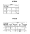
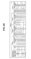
- FIG. 5 contains diagrams showing an example of the correspondence table of the number of spatial multiplexing sequences, orthogonal resources and code point according to this Embodiment.
- the length of the cyclic shift in the time domain is described as a phase rotation amount for each subcarrier to multiply in the frequency domain.
- FIG. 5A is a table showing combinations of orthogonal resources used in the DMRS that can be set by the number-of-spatial multiplexing sequence/orthogonal resource setting part 3013 in the case where the number of spatial multiplexing sequences is "1", and code points associated with the combinations. For example, when the number-of-spatial multiplexing sequence/orthogonal resource setting part 3013 sets the number of spatial multiplexing sequences at "1", the cyclic shift at "0", and the orthogonal cover at [1,1] for the mobile station apparatus 1, the number-of-spatial multiplexing sequence/orthogonal resource setting part 3013 generates "000" as a code word to arrange in the information indicative of orthogonal resources.
- FIG. 5B is a table showing combinations of orthogonal resources used in the DMRS that can be set by the number-of-spatial multiplexing sequence/orthogonal resource setting part 3013 in the case where the number of spatial multiplexing sequences is "2", and code points associated with the combinations.
- the number-of-spatial multiplexing sequence/orthogonal resource setting part 3013 sets the number of spatial multiplexing sequences at "2", the cyclic shift of port 1 at "0", the orthogonal cover of port 1 at [1,1], the cyclic shift of port 2 at "n”, and the orthogonal cover of port 2 at [1, 1] for the mobile station apparatus 1, the number-of-spatial multiplexing sequence/orthogonal resource setting part 3013 generates "000" as a code word to arrange in the information indicative of orthogonal resources.
- FIG. 5C is a table showing combinations of orthogonal resources used in the DMRS that can be set by the number-of-spatial multiplexing sequence/orthogonal resource setting part 3013 in the case where the number of spatial multiplexing sequences is "3", and code points associated with the combinations.
- the number-of-spatial multiplexing sequence/orthogonal resource setting part 3013 sets the number of spatial multiplexing sequences at "3", the cyclic shift of port 1 at "0", the orthogonal cover of port 1 at [1,1] the cyclic shift of port 2 at " ⁇ /2", the orthogonal cover of port 2 at [1, -1], the cyclic shift of port 3 at " ⁇ ”, and the orthogonal cover of port 3 at [1, 1] for the mobile station apparatus 1, the number-of-spatial multiplexing sequence/orthogonal resource setting part 3013 generates "000" as a code word to arrange in the information indicative of orthogonal resources.
- FIG. 5D is a table showing combinations of orthogonal resources used in the DMRS that can be set by the number-of-spatial multiplexing sequence/orthogonal resource setting part 3013 in the case where the number of spatial multiplexing sequences is "4", and code points associated with the combinations.
- the number-of-spatial multiplexing sequence/orthogonal resource setting part 3013 sets the number of spatial multiplexing sequences at "4", the cyclic shift of port 1 at "0", the orthogonal cover of port 1 at [1, 1] the cyclic shift of port 2 at " ⁇ /2", the orthogonal cover of port 2 at [1, 1], the cyclic shift of port 3 at "n”, the orthogonal cover of port 3 at [1, 1], the cyclic shift of port 4 at "3 ⁇ /2", and the orthogonal cover of port 4 at [1, 1] for the mobile station apparatus 1, the number-of-spatial multiplexing sequence/orthogonal resource setting part 3013 generates "000" as a code word to arrange in the information indicative of orthogonal resources.
- the number-of-spatial multiplexing sequence/orthogonal resource setting part 3013 selects a code point to arrange in the information indicative of orthogonal resources from combinations of the rank and orthogonal resources set on the mobile station apparatus 1.
- the information indicative of the orthogonal resources is the same code point, interpretation of the code point is different corresponding to the number of spatial multiplexing sequences.
- the control part 303 generates a control signal to control the reception part 305 and the transmission part 307, based on the control information from the higher layer processing part 301.
- the control part 303 outputs the generated control signal to the reception part 305 and the transmission part 307 to control the reception part 305 and the transmission part 307.
- the reception part 305 demultiplexes, demodulates and decodes the reception signal received from the mobile station apparatus 1 via the transmission/reception antenna, and outputs the decoded information to the higher layer processing part 301.
- the radio reception part 3057 convers (down-converts) each uplink signal received via the transmission/reception antenna into a signal of an intermediate frequency, removes unnecessary frequency components, controls the amplification level so that the signal level is properly maintained, performs quadrature demodulation based on the in-phase component and quadrature component of the received signal, and converts the quadrature-demodulated analog signal into a digital signal.
- the radio reception part 3057 removes a portion corresponding to a guard interval (GI) from the converted digital signal.
- the radio reception part 3057 performs Fast Fourier Transform (FFT) on the signal from which the guard interval is removed, and extracts the signal in the frequency domain to output to the demultiplexing part 3055.
- FFT Fast Fourier Transform
- the demultiplexing part 3055 demultiplexes the signal input from the radio reception part 3057 into signals of the PUCCH, PUSCH, Uplink Reference Signals (DMRS, SRS) and the like. In addition, this demultiplexing is performed based on the allocation information of radio resources included in the Uplink grant which is beforehand determined by the base station apparatus 3 and notified to each mobile station apparatus 1. Further, the demultiplexing part 3055 outputs the demultiplexed PUSCH and Uplink Reference Signals (DMRS, SRS) to the channel measurement part 309. Furthermore, the demultiplexing part 3055 performs channel compensation of the PUCCH and/or PUSCH from the estimation value of the uplink channel input from the channel measurement part 309.
- DMRS Uplink Reference Signals
- the demultiplexing part 3055 divides the time and frequency positions to which data of respective ports is spatially multiplexed, and further, divides the data of respective ports.
- the demodulation part 3053 performs Inverse Discrete Fourier Transform (IDFT) on the PUSCH, acquires modulation symbols, and with respect to the modulation symbols of the PUCCH and PUSCH, demodulates the reception signal using a modulation scheme of Binary Phase Shift Keying (BPSK), Quadrature Phase Shift Keying (QPSK), 16 Quadrature Amplitude Modulation (16QAM), 64 Quadrature Amplitude Modulation (64QAM) or the like which is beforehand determined or the base station apparatus 3 beforehand notifies each mobile station apparatus 1 in the Uplink grant.
- BPSK Binary Phase Shift Keying
- QPSK Quadrature Phase Shift Keying
- 16QAM 16 Quadrature Amplitude Modulation
- 64QAM 64 Quadrature Amplitude Modulation
- the decoding part 3051 decodes coded bits of the demodulated PUCCH and PUSCH with a coding rate which is beforehand determined or the base station apparatus 3 beforehand notifies the mobile station apparatus 1 in the Uplink grant of a beforehand determined coding scheme, and outputs the decoded data information and Uplink Control Information to the higher layer processing part 301.
- the channel measurement part 309 estimates the state of the channel from the PUSCH and Uplink Reference Signals (DMRS, SRS) input from the demultiplexing part 3055, and outputs the estimated channel estimation value to the demultiplexing part 3055 and higher layer processing part 301.
- DMRS Uplink Reference Signals
- the transmission part 307 generates a Downlink Reference Signal according to the control signal input from the control part 303, encodes and modulates the data information and Downlink Control Information input from the higher layer processing part 301, and multiplexes the PDCCH, PDSCH and Downlink Reference signal to transmit to the mobile station apparatus 1 via the transmission/reception antenna.
- the coding part 3071 performs coding such as turbo coding, convolutional coding, block coding and the like on the Downlink Control Information and data information of each downlink component carrier input from the higher layer processing part 301.
- the modulation part 3073 modulates coded bits input from the coding part 3071 with the modulation scheme of QPSK, 16QAM, 64QAM or the like.
- the downlink reference signal generation part 3079 generates, as a Downlink Reference Signal, a sequence that the mobile station apparatus 1 knows and that is obtained by a rule beforehand determined based on a cell identifier (Cell ID) to identify the base station apparatus 3 or the like.
- Cell ID cell identifier
- the multiplexing part 3075 multiplexes each modulated channel and the generated Downlink Reference Signal.
- the radio transmission part 3077 performs Inverse Fast Fourier Transform (IFFT) on the multiplexed modulation symbol, performs modulation of the OFDM scheme, adds a guard interval to the OFDM-modulated OFDM symbol, generates a baseband digital signal, converts the baseband digital signal into an analog signal, generates an in-phase component and quadrature component of the intermediate frequency from the analog signal, removes excessive frequency components with respect to the intermediate frequency band, converts (up-converts) the signal of the intermediate frequency into a signal of a high frequency, removes excessive frequency components, amplifies power, and outputs the signal to the transmission/reception antenna to transmit.
- IFFT Inverse Fast Fourier Transform
- FIG. 6 is a schematic block diagram illustrating a configuration of the mobile station apparatus 1 according to this Embodiment.
- the mobile station apparatus 1 includes higher layer processing parts 101, control parts 103, reception parts 105, transmission parts 107, and transmission/reception antennas and is comprised thereof.
- the higher layer processing part 101 includes a radio resource control part 1011, number-of-spatial multiplexing sequence/orthogonal resource identification part 1013 and storage part 1015 and is comprised thereof.
- the reception part 105 includes a decoding part 1051, demodulation part 1053, demultiplexing part 1055 and radio reception part 1057 and is comprised thereof.
- the transmission part 107 includes a coding part 1071, modulation part 1073, multiplexing part 1075, radio transmission part 1077, and uplink reference signal generation part 1079 and is comprised thereof.
- the higher layer processing part 101 outputs uplink data information generated by user operation or the like to the transmission part 107. Further, the higher layer processing part 101 performs processing of the Packet Data Convergence Protocol layer, Radio Link Control layer and Radio Resource Control layer.
- the radio resource control part 1011 provided in the higher layer processing part 101 manages various kinds of setting information of the apparatus 1. Further, the radio resource control part 1011 generates information to arrange in each channel in uplink to output to the transmission part 107. The radio resource control part 1011 generates control information to control the reception part 105 and the transmission part 107 to output to the control part 103, based on the Downlink Control Information (for example, Uplink grant, etc.) notified on the PDCCH from the base station apparatus 3, and various kinds of setting information of the apparatus 1 managed in the radio resource control part 1011.
- the Downlink Control Information for example, Uplink grant, etc.
- the number-of-spatial multiplexing sequence/orthogonal resource identification part provided in the higher layer processing part 101 identifies the number of spatial multiplexing sequences from the information indicative of the number of spatial multiplexing sequences included in the Uplink grant. Further, the number-of-spatial multiplexing sequence/orthogonal resource identification part 1013 refers to the storage part 1015, and identifies orthogonal resources used in the DMRS, based on the information indicative of the number of spatial multiplexing sequences and information indicative of the orthogonal resources used in the DMRS included in the Uplink grant.
- the number-of-spatial multiplexing sequence/orthogonal resource identification part 1013 generates control information to control the transmission part 107 so as to transmit the PUSCH as the identified number of spatial multiplexing sequences, and arrange the DMRS to be time-multiplexed with the PUSCH in the identified orthogonal resources, and outputs the control information to the control part 103.
- the storage part 1015 provided in the higher layer processing part 101 stores the same correspondence table as the correspondence table of the number of spatial multiplexing sequences, orthogonal resources and the code point stored in the storage part 3015 of the base station apparatus 3. For example, when the information indicative of the number of spatial multiplexing sequences indicates "1", and the code word of the information indicative of orthogonal resources used in the DMRS is "000", from the correspondence table in FIG. 5A , it is possible to identify that the cyclic shift of orthogonal resources used in the DMRS is "0", and that the orthogonal cover is [1,1].
- the control part 103 generates a control signal to control the reception part 105 and the transmission part 107, based on the control information from the higher layer processing part 101.
- the control part 103 outputs the generated control signal to the reception part 105 and the transmission part 107 to control the reception part 105 and the transmission part 107.
- the reception part 105 demultiplexes, demodulates and decodes the reception signal received from the base station apparatus 3 via the transmission/reception antenna, and outputs the decoded information to the higher layer processing part 101.
- the radio reception part 1057 convers (down-converts) a signal of each uplink component carrier received via each transmission/reception antenna into a signal of an intermediate frequency, removes unnecessary frequency components, controls the amplification level so that the signal level is properly maintained, performs quadrature demodulation based on the in-phase component and quadrature component of the received signal, and converts the quadrature-demodulated analog signal into a digital signal.
- the radio reception part 1057 removes a portion corresponding to a guard interval from the converted digital signal, performs Fast Fourier Transform on the signal from which the guard interval is removed, and extracts the signal in the frequency domain.
- the demultiplexing part 1055 demultiplexes the extracted signal into the PUCCH, PUSCH, and Downlink Reference Signal. In addition, this demultiplexing is performed based on the allocation information of radio resources notified by the Downlink Control Information, etc. Further, the demultiplexing part 1055 obtains an estimation value of the channel from the demultiplexed Downlink Reference Signal and performs channel compensation of the PDCCH and PDSCH.
- the demodulation part 1053 demodulates the PDCCH with the QPSK modulation scheme to output to the decoding part 1051.
- the decoding part 1051 attempts to decode the PDCCH, and when the part succeeds in decoding, outputs the decoded Downlink Control Information to the higher layer processing part 101.
- the demodulation part 1053 demodulates the PDSCH with the modulation scheme of QPSK, 16QAM, 64QAM or the like notified by the Downlink Control Information to output to the decoding part 1051.
- the decoding part 1051 performs decoding associated with the coding rate notified by the Downlink Control Information, and outputs the decoded data information to the higher layer processing part 101.
- the transmission part 107 generates an Uplink Reference Signal according to the control signal input from the control part 103, encodes and modulates the data information input from the higher layer processing part 101, and multiplexes the PUCCH, PUSCH and generated Uplink Reference Signal to transmit to the base station apparatus 3 via the transmission/reception antenna.
- the coding part 1071 performs coding such as turbo coding, convolutional coding, block coding and the like on the Uplink Control Information and data information input from the higher layer processing part 101.
- the modulation part 1073 modulates coded bits input from the coding part 1071 with the modulation scheme of BPSK, QPSK, 16QAM, 64QAM or the like. Further, the modulation part 1073 rearranges modulation symbols for ports corresponding to the number of spatial multiplexing sequences, and performs precoding on the signal for spatial multiplexing.
- which precoding the mobile station apparatus 1 performs is set by the base station apparatus 3, and the base station apparatus 3 includes information indicative of the precoding in the Uplink grant to transmit to the mobile station apparatus 1.
- the uplink reference signal generation part 1079 generates a CAZA sequence that the base station apparatus 3 knows and that is obtained by a rule beforehand determined based on a cell identifier to identify the base station apparatus 3, the bandwidth of the PUSCH, etc. Further, the uplink reference signal generation part 1079 applies the cyclic shift and the orthogonal cover to the CAZAC sequence, according to the orthogonal resources of the DMRS identified by the number-of-spatial multiplexing sequence/orthogonal resource identification part 1013.
- the multiplexing part 1075 rearranges the modulation symbols of the PUSCH to parallel, then performs Discrete Fourier Transform (DFT), and multiplexes the signal of the DFT-processed PUSCH, the signal of the PUCCH and the Uplink Reference Signal (DMRS and/or SRS).
- DFT Discrete Fourier Transform
- DMRSs of different orthogonal resources are time-multiplexed for each port of the PUSCH.
- the radio transmission part 1077 performs Inverse Fast Fourier Transform on the multiplexed signal, performs modulation of the SC-FDMA scheme, adds a guard interval to the SC-FDMA-modulated SC-FDMA symbol, generates a baseband digital signal, converts the baseband digital signal into an analog signal, generates an in-phase component and quadrature component of the intermediate frequency from the analog signal, removes excessive frequency components with respect to the intermediate frequency band, converts (up-converts) the signal of the intermediate frequency into a signal of a high frequency, removes excessive frequency components, amplifies power, and outputs the signal to the transmission/reception antenna to transmit.
- FIG. 7 is a flowchart showing an example of the operation of the base station apparatus 3 according to this Embodiment.
- the base station apparatus 3 estimates the channel state from the PUSCH, DMRS, and SRS received from the mobile station apparatus 1, sets the number of spatial multiplexing sequences that the mobile station apparatus 1 applies in transmitting the PUSCH, and allocates orthogonal resources of the DMRS which is time-multiplexed with the PUSCH and transmitted (step S100).
- the base station apparatus 3 selects a code word to arrange in the information indicative of the orthogonal resources of the DMRS from the number of spatial multiplexing sequences and the orthogonal resources assigned in step S100 (step S101), and generates the information indicative of the orthogonal resources including the selected code word and information indicative of the number of spatial multiplexing sequences (step S102).
- the base station apparatus 3 includes the generated information indicative of the orthogonal resources and the generated information indicative of the number of spatial multiplexing sequences in an Uplink grant to transmit on the PDCCH (step S103).
- FIG. 8 is a flowchart showing an example of the operation of the mobile station apparatus 1 according to this Embodiment.
- the mobile station apparatus 1 receives the Uplink grant transmitted from the base station apparatus 3 (step S200), identifies the number of spatial multiplexing sequences used in transmission of the PUSCH from the information indicative of the number of spatial multiplexing sequences included in the Uplink grant (step S201), and identifies the orthogonal resources used in the DMRS from the identified number of spatial multiplexing sequences, and the information indicative of the orthogonal resources used in the DMRS included in the Uplink grant (step S202).
- the mobile station apparatus 1 spatially multiplexes the PUSCH with the number of spatial multiplexing sequences, and multiplexes the DMRS of the identified orthogonal resources into each port of the PUSCH to transmit to the base station apparatus 3 (step S203).
- the base station apparatus 3 sets the number (rank) of spatial multiplexing sequences of data used by the mobile station apparatus 1 in transmitting a PUSCH, further sets orthogonal resources used by the mobile station apparatus 1 for the reference signal (DMRS) that is transmitted together with the PUSCH, selects a code point to arrange in information (first control information) indicative of the orthogonal resources based on the set orthogonal resources and the set number of spatial multiplexing sequences, and transmits downlink control information (Uplink grant) including at least the information indicative of the orthogonal resources and information (second control information) indicative of the number of spatial multiplexing sequences to the mobile station apparatus 1.
- DMRS reference signal
- the mobile station apparatus 1 receives the Downlink Control Information (Uplink grant) transmitted from the base station apparatus 3, selects orthogonal resources used in the reference signal (DMRS) set by the base station apparatus 3 from the information indicative of the orthogonal resources and the information indicative of the number of spatial multiplexing sequences included in the Uplink grant, applies the selected orthogonal resources to generate the reference signal (DMRS), and transmits the reference signal to the base station apparatus 3 together with the PUSCH.
- DMRS Downlink Control Information
- DMRS reference signal
- a wireless communication system of the invention is a wireless communication system in which a base station apparatus and at least one mobile station apparatus communicate with each other, and is characterized in that the base station apparatus sets the number (rank) of spatial multiplexing sequences of data used by the mobile station apparatus in transmitting a PUSCH, further sets orthogonal resources used by the mobile station apparatus for a reference signal that is transmitted together with the PUSCH, selects a code point to arrange in first control information indicative of orthogonal resources based on the set orthogonal resources and the set number of spatial multiplexing sequences, and transmits downlink control information including at least the first control information and second control information indicative of the set number of spatial multiplexing sequences to the mobile station apparatus, and that the mobile station apparatus receives the downlink control information, selects orthogonal resources to apply to the reference signal set by the base station apparatus from the first control information and the second control information included in the downlink control information, applies the selected orthogonal resources
- the orthogonal resources of the invention are characterized by being comprised of a combination of a length of the cyclic shift on the reference signal in the time domain, and an orthogonal code sequence (orthogonal cover) applied to the reference signal that is transmitted twice or more in a plurality of time symbols.
- a base station apparatus of the invention is a base station apparatus applied to a wireless communication system in which the base station apparatus and at least one mobile station apparatus communicate with each other, and is characterized by setting the number (rank) of spatial multiplexing sequences of data used by the mobile station apparatus in transmitting a PUSCH, further setting orthogonal resources used by the mobile station apparatus for a reference signal that is transmitted together with the PUSCH, selecting a code point to arrange in first control information indicative of orthogonal resources based on the set orthogonal resources and the set number of spatial multiplexing sequences, and transmitting downlink control information including at least the first control information and second control information indicative of the set number of spatial multiplexing sequences to the mobile station apparatus.
- a mobile station apparatus of the invention is a mobile station apparatus applied to a wireless communication system in which a base station apparatus and at least one mobile station apparatus communicate with each other, and is characterized by receiving downlink control information including at least first control information for the base station apparatus to select a code point from combinations of the number of spatial multiplexing sequences(rank) of data, which is the number being used by the mobile station apparatus when the mobile station apparatus transmits a PUSCH, and orthogonal resources used in a reference signal that is transmitted together with the PUSCH, and second control information indicative of the number of spatial multiplexing sequences, selecting orthogonal resources to use in the reference signal set by the base station apparatus from the first control information and the second control information included in the downlink control information, applying the selected orthogonal resources to generate the reference signal, and transmitting the reference signal to the base station apparatus.
- downlink control information including at least first control information for the base station apparatus to select a code point from combinations of the number of spatial multiplexing sequences(rank) of data, which is the number being used by
- a wireless communication method of the invention is a wireless communication method applied to a wireless communication system in which a base station apparatus and at least one mobile station apparatus communicate with each other, and is characterized by having means for setting the number (rank) of spatial multiplexing sequences of data used by the mobile station apparatus in transmitting a PUSCH, means for setting orthogonal resources used by the mobile station apparatus for a reference signal that is transmitted together with the PUSCH, means for selecting a code point to arrange in first control information indicative of orthogonal resources based on the set orthogonal resources and the set number of spatial multiplexing sequences, and means for transmitting downlink control information including at least the first control information and second control information indicative of the set number of spatial multiplexing sequences to the mobile station apparatus.
- a wireless communication method of the invention is a wireless communication method applied to a wireless communication system in which a base station apparatus and at least one mobile station apparatus communicate with each other, and is characterized in that the mobile station apparatus has means for receiving downlink control information including at least first control information for the base station apparatus to select a code point from combinations of the number of spatial multiplexing sequences(rank) of data, which is the number being used by the mobile station apparatus when the mobile station apparatus transmits a PUSCH, and orthogonal resources used in a reference signal that is transmitted together with the PUSCH, and second control information indicative of the number of spatial multiplexing sequences, means for selecting orthogonal resources to use in the reference signal set by the base station apparatus from the first control information and the second control information included in the downlink control information, and means for applying the selected orthogonal resources to generate the reference signal, and transmitting the reference signal to the base station apparatus.
- downlink control information including at least first control information for the base station apparatus to select a code point from combinations of the number of spatial multiplexing sequences
- Programs operating in the base station apparatus 3 and the mobile station apparatus 1 related to the invention may be programs (programs that cause the computer to function) which control the CPU (Central Processing Unit) and the like, to achieve the functions of the above-mentioned Embodiment related to the invention. Then, the information handled in the apparatuses is temporarily stored in RAM (Random Access Memory) at the time of the processing, subsequently stored in various kinds of ROM such as Flash ROM (Read Only Memory) and HDD (Hard Disk), and when necessary, read out by the CPU to be modified and written.
- RAM Random Access Memory
- ROM Read Only Memory
- HDD Hard Disk
- a part or the whole of the mobile station apparatus 1 and base station apparatus 3 in the above-mentioned Embodiment may be actualized by the computer.
- the program to actualize the control function may be stored in a computer readable storage medium, and the program stored in the storage medium may be read by a computer system and executed to actualize.
- the "computer system” described herein is the computer system incorporated into the mobile station apparatus 1 or the base station apparatus 3, and is assumed to include the OS and hardware of peripheral devices and the like.
- the "computer readable storage medium” means transportable media such as a flexible disk, magneto-optical disk, ROM, CD-ROM and the like, and storage devices such as a hard disk and the like incorporated into the computer system.
- the "computer readable storage medium” may include media that dynamically hold the program for a short time, such as communication lines in the case where the program is transmitted via communication channels of a network such as the Internet and telephone lines, and media that hold the program for a certain time, such as volatile memory inside the computer system that is the server or client in this case.
- the above-mentioned programs may be to actualize a part of the functions as described previously, and further, may be to actualize the functions as described previously in combination of a program already stored in the computer system.
- a part or the whole of the mobile station apparatus 1 and base station apparatus 3 in the above-mentioned Embodiment may be actualized as LSI that is typically an integrated circuit.
- Each function block of the mobile station apparatus 1 and base station apparatus 3 may be made in chip form separately, or a part or the whole of the blocks may be integrated and made in chip form.
- the technique of integrated circuits is not limited to the LSI, and may be achieved by dedicate circuits or general-purpose processor.
- the technique of integrated circuits as a substitute for the LSI appears as semiconductor techniques progress, it is possible to use the integrated circuit by the technique.
Abstract
Description
- The present invention relates to a wireless communication system, base station apparatus, mobile station apparatus, wireless communication method and integrated circuit.
- Conventionally, the 3rd Generation Partnership Project (3GPP) has studied evolution (hereinafter, referred to as "Long Term Evolution (LTE)" or "Evolved Universal Terrestrial Radio Access (EUTRA)") of radio access scheme and radio networks of cellular mobile communication, and radio access scheme and radio networks (hereinafter, referred to as "Long Term Evolution-Advanced (LTE-A)" or "Advanced Evolved Universal Terrestrial Radio Access (A-EUTRA)") for actualizing faster data communications using frequency bands wider than LTE.
- In LTE, an Orthogonal Frequency Division Multiplexing (OFDM) scheme that is multicarrier transmission is used as a communication scheme of wireless communication (downlink) from a base station apparatus to a mobile station apparatus. Further, an SC-FDMA (Single-Carrier Frequency Division Multiple Access) scheme that is single-carrier transmission is used as a communication scheme of wireless communication (uplink) from the mobile station apparatus to the base station apparatus. More specifically, a modulated transmission signal is transformed into the signal in the frequency domain by DFT (Discrete Fourier Transform), and the signal is mapped to radio resources (frequency resources) allocated by the base station apparatus, then is transformed into the signal in the time domain by IDFT (Inverse DFT) and is transmitted to the base station apparatus. In LTE-A, SC-FDMA is also referred to as DFT-precoded OFDM.
- In LTE, in downlink are assigned the Synchronization Channel(SCH), Physical Broadcast Channel (PBCH), Physical Downlink Control Channel (PDCCH), Physical Downlink Shared Channel (PDSCH), Physical Multicast Channel (PMCH), Physical Control Format Indicator Channel (PCFICH), and Physical Hybrid automatic repeat request Indicator Channel (PHICH). Further, in uplink are assigned the Physical Uplink Shared Channel (PUSCH), Physical Uplink Control Channel (PUCCH), and Physical Random Access Channel (PRACH).
- In LTE, a reference signal (Demodulation Reference signal; DMRS) used in demodulation of the PUSCH and PUCCH is time-multiplexed with the PUSCH or PUCCH and transmitted. The DMRS is subjected to code spreading using CAZAC (Constant Amplitude and Zero Auto-Correlation) sequences in radio resources divided with SC-FDMA assumed. The CAZAC sequences are sequences that have constant amplitude in the time domain and the frequency domain and that are excellent in auto-correlation characteristics. The sequences have constant amplitude in the time domain, and are thereby capable of controlling the PAPR (Peak to Average Power Ratio) to within low levels. Further, in the DMRS of LTE, by providing SC-FDMA symbols with the cyclic shift in the time domain, it is possible to perform CDM (Code Division Multiplex) on the DMRS spread using the same CAZAC sequence. However, when the sequence lengths of CAZAC sequences are different from one another, it is not possible to perform CDM. The generation method of DMRS in LTE is described in
Non-patent Document 1, section 5. - Non-patent
Document 2 proposes further applying orthogonal code (for example, Walsh-Hadamard Code [1,1] and [1,-1]) to DMRSs that are transmitted in different SC-FDMA symbols, in addition to above-mentioned CDM by cyclic shift, in order to enable uplink multi user spatial multiplexing (or also referred to as Uplink Multi User Multiple Input Multiple Output; UL MU-MIMO) between mobile station apparatuses assigned different radio resources in LTE. Hereinafter, the orthogonal code is referred to as orthogonal cover. -
- Non-patent Document 1: "3GPP TS36.211 v.8.8.0 (2009-09)"
- Non-patent Document 2: "Uplink reference signal structure from MU-MIMO viewpoint", 3GPP TSG RAN WG1 Meeting #58bis, R1-093917, October 12-16, 2009.
- However, in conventional techniques, the base station apparatus notifies the mobile station apparatus of the length of the cyclic shift on the DMRS in the time domain using the PDCCH, additional control information is required to further notify of the orthogonal cover to apply to the DMRS, and there has been the problem that overhead of the PDCCH increases.
- The present invention was made in view of the aforementioned respect, and it is an object of the invention to provide a wireless communication system, base station apparatus, mobile station apparatus, wireless communication method and integrated circuit for enabling the length of the cyclic shift on the DMRS in the time domain and orthogonal cover that the base station apparatus assigns to the mobile station apparatus to be flexibly notified with the same overhead of the PDCCH as conventional overhead kept.
- (1) To attain the aforementioned object, the invention took measures as described below. In other words, a wireless communication system of the invention is a wireless communication system in which a base station apparatus and a mobile station apparatus communicate with each other, and is characterized in that the base station apparatus sets the number of spatial multiplexing sequences (rank) of data , which is the number being used by the mobile station apparatus when the mobile station apparatus transmits a PUSCH, further sets orthogonal resources used by the mobile station apparatus respectively for the same number of reference signals as the set number of spatial multiplexing sequences which are transmitted together with the PUSCH, and transmits downlink control information including information indicative of the set number of spatial multiplexing sequences and information indicative of the set orthogonal resources used for the reference signals, and the mobile station apparatus receives the downlink control information, selects orthogonal resources to respectively apply to the same number of reference signals as the number of spatial multiplexing sequences indicated by the information indicative of the number of spatial multiplexing sequences from the information indicative of the orthogonal resources, and applies the selected orthogonal resources to generate the reference signals, and transmits the generated reference signals to the base station apparatus.
- (2) Further, in the wireless communication system of the invention, it is a feature that the orthogonal resources are comprised of a combination of a length of a cyclic shift on the reference signals in the time domain, and an orthogonal code sequence (orthogonal cover) applied to the reference signals that are transmitted twice or more in a plurality of time symbols.
- (3) Furthermore, in the wireless communication system of the invention, it is a feature that the number of bits used in the information indicative of the orthogonal resources is a beforehand determined value.
- (4) Still furthermore, in the wireless communication system of the invention, it is a feature that orthogonal resources associated with a code point of the information indicative of the orthogonal resources vary with spatial multiplexing sequences of data used by the mobile station apparatus in transmitting the PUSCH.
- (5) Moreover, in the wireless communication system of the invention, it is a feature that a first code point of the information indicative of the orthogonal resources indicates that the same orthogonal code sequence (orthogonal cover) is applied to all of the same number of reference signals as the set number of spatial multiplexing sequences, and that a second code point of the information indicative of the orthogonal resources indicates that a plurality of different orthogonal code sequences is applied to the same number of reference signals as the set number of spatial multiplexing sequences.
- (6) Further, a base station apparatus of the invention is a base station apparatus that communicates with a mobile station apparatus, and is characterized by setting the number of spatial multiplexing sequences (rank) of data , which is the number being used by the mobile station apparatus when the mobile station apparatus transmits a PUSCH, further setting orthogonal resources used by the mobile station apparatus respectively for the same number of reference signals as the set number of spatial multiplexing sequences which are transmitted together with the PUSCH, and transmitting downlink control information including information indicative of the set number of spatial multiplexing sequences and information indicative of the set orthogonal resources used for the reference signals.
- (7) Furthermore, a mobile station apparatus of the invention is a mobile station apparatus that communicates with a base station apparatus, and is characterized by receiving downlink control information, transmitted from the base station apparatus, including information indicative of the number of spatial multiplexing sequences (rank) of data, which is the number being used by the mobile station apparatus when the mobile station apparatus transmits a PUSCH, and information indicative of orthogonal resources respectively used for the same number of reference signals as the number of spatial multiplexing sequences of the PUSCH which are transmitted together with the PUSCH, selecting orthogonal resources to respectively apply to the same number of reference signals as the number of spatial multiplexing sequences indicated by the information indicative of the number of spatial multiplexing sequences from the information indicative of the orthogonal resources, and applying the selected orthogonal resources to generate the reference signals, and transmitting the generated reference signals to the base station apparatus.
- (8) Further, a wireless communication method of the invention is a wireless communication method used in a base station apparatus that communicates with a mobile station apparatus, and is characterized by having means for setting the number of spatial multiplexing sequences (rank) of data , which is the number being used by the mobile station apparatus when the mobile station apparatus transmits a PUSCH, means for setting orthogonal resources used by the mobile station apparatus respectively for the same number of reference signals as the set number of spatial multiplexing sequences which are transmitted together with the PUSCH, and means for transmitting downlink control information including information indicative of the set number of spatial multiplexing sequences and information indicative of the set orthogonal resources used for the reference signals.
- (9) Furthermore, a wireless communication method of the invention is a wireless communication method used in a mobile station apparatus that communicates with a base station apparatus, and is characterized by having means for receiving downlink control information, transmitted from the base station apparatus, including information indicative of the number of spatial multiplexing sequences (rank) of data, which is the number being used by the mobile station apparatus when the mobile station apparatus transmits a PUSCH, and information indicative of orthogonal resources respectively used for the same number of reference signals as the number of spatial multiplexing sequences of the PUSCH which are transmitted together with the PUSCH, means for selecting orthogonal resources to respectively apply to the same number of reference signals as the number of spatial multiplexing sequences indicated by the information indicative of the number of spatial multiplexing sequences from the information indicative of the orthogonal resources, and means for applying the selected orthogonal resources to generate the reference signals, and transmitting the generated reference signals to the base station apparatus.
- (10) Further, an integrated circuit of the invention is an integrated circuit used in in a base station apparatus that communicates with a mobile station apparatus, and is characterized by making a series of means chip form to be executable where the series of means includes means for setting the number of spatial multiplexing sequences (rank) of data , the number being used by the mobile station apparatus when the mobile station apparatus transmits a PUSCH, means for setting orthogonal resources used by the mobile station apparatus respectively for the same number of reference signals as the set number of spatial multiplexing sequences which are transmitted together with the PUSCH, and means for transmitting downlink control information including information indicative of the set number of spatial multiplexing sequences and information indicative of the set orthogonal resources used for the reference signals.
- (11) Furthermore, an integrated circuit of the invention is an integrated circuit used in a mobile station apparatus that communicates with a base station apparatus, and is characterized by making a series of means chip form to be executable where the series of means includes means for receiving downlink control information, transmitted from the base station apparatus, including information indicative of the number of spatial multiplexing sequences (rank) of data, which is the number being used by the mobile station apparatus when the mobile station apparatus transmits a PUSCH, and information indicative of orthogonal resources respectively used for the same number of reference signals as the number of spatial multiplexing sequences of the PUSCH which are transmitted together with the PUSCH, means for selecting orthogonal resources to respectively apply to the same number of reference signals as the number of spatial multiplexing sequences indicated by the information indicative of the number of spatial multiplexing sequences from the information indicative of the orthogonal resources, and means for applying the selected orthogonal resources to generate the reference signals, and transmitting the generated reference signals to the base station apparatus.
- According to the invention, it is possible to notify of the length of the cyclic shift on the DMRS in the time domain and orthogonal cover that the base station apparatus assigns to the mobile station apparatus to be flexibly notified with the same overhead of the PDCCH as conventional overhead kept.
-
-
FIG. 1 is a conceptual diagram of a wireless communication system according to this Embodiment; -
FIG. 2 is a schematic diagram showing an example of a configuration of an uplink radio frame according to this Embodiment; -
FIG. 3 is a schematic diagram showing an example of a configuration of DMRS according to this Embodiment; -
FIG. 4 is a schematic block diagram illustrating a configuration of abase station apparatus 3 according to this Embodiment; -
FIG. 5A is a diagram showing an example of a correspondence table of the number of spatial multiplexing sequences, orthogonal resources and code point according to this Embodiment; -
FIG. 5B is another diagram showing an example of the correspondence table of the number of spatial multiplexing sequences, orthogonal resources and code point according to this Embodiment; -
FIG. 5C is still another diagram showing an example of the correspondence table of the number of spatial multiplexing sequences, orthogonal resources and code point according to this Embodiment; -
FIG. 5D is further another diagram showing an example of the correspondence table of the number of spatial multiplexing sequences, orthogonal resources and code point according to this Embodiment; -
FIG. 6 is a schematic block diagram illustrating a configuration of amobile station apparatus 1 according to this Embodiment; -
FIG. 7 is a flowchart showing an example of the operation of thebase station apparatus 3 according to this Embodiment; and -
FIG. 8 is a flowchart showing an example of the operation of themobile station apparatus 1 according to this Embodiment. - An Embodiment of the invention will be described below with reference to drawings.
FIG. 1 is a conceptual diagram of a wireless communication system according to this Embodiment. InFIG. 1 , the wireless communication system is provided with mobile station apparatuses 1A to 1C and abase station apparatus 3. The mobile station apparatuses 1A to 1C andbase station apparatus 3 perform communications using frequency band aggregation, described later. -
FIG. 1 shows that the Synchronization Channel(SCH), Downlink Reference Signal (DL RS), Physical Broadcast Channel (PBCH), Physical Downlink Control Channel (PDCCH), Physical Downlink Shared Channel (PDSCH), Physical Multicast Channel (PMCH), Physical Control Format Indicator Channel (PCFICH), and Physical Hybrid ARQ Indicator Channel (PHICH) are assigned in wireless communication (downlink) from thebase station apparatus 3 to the mobile station apparatuses 1A to 1C. - Further,
FIG. 1 shows that the Uplink Reference Signal (UL RS), Physical Uplink Control Channel (PUCCH), Physical Uplink Shared Channel (PUSCH), and Physical Random Access Channel (PRACH) are assigned in wireless communication (uplink) from the mobile station apparatuses 1A to 1C to thebase station apparatus 3. The Uplink Reference Signal includes a DMRS (Demodulation Reference Signal) which is time-multiplexed with the PUSCH or PUCCH to be transmitted and is used for channel compensation of the PUSCH and PUCCH, and an SRS (Sounding Reference Signal) used for thebase station apparatus 3 to estimate an uplink channel state. Hereinafter, the mobile station apparatuses 1A to 1C are referred to as amobile station apparatus 1. -
FIG. 2 is a schematic diagram showing an example of a configuration of an uplink radio frame according to this Embodiment. InFIG. 2 , the horizontal axis represents the time domain, and the vertical axis represents the frequency domain. As shown inFIG. 2 , an uplink radio frame is comprised of a plurality of uplink Physical Resource Block (PRB) pairs (for example, region enclosed by dashed lines inFIG. 2 ). This uplink Physical Resource Block pair is a unit for radio resource allocation and the like, and is comprised of a frequency band (PRB bandwidth; 180 kHz) and time band (two slots=one subframe; 1ms) with beforehand determined widths. A single uplink Physical Resource Block pair is comprised of two uplink Physical Resource Blocks (PRB bandwidth x slots) consecutive in the time domain. A single uplink Physical Resource Block (unit enclosed by bold line inFIG. 2 ) is comprised of 12 subcarriers (15 kHz) in the frequency domain and 7 SC-FDMA symbols (71 µs ) in the time domain. - In the time domain, there are a slot (0.5 ms) comprised of 7 SC-FDMA (Single-Carrier Frequency Division Multiple Access) symbols, sub-frame (1 ms) comprised of two slots, and radio frame (10 ms) comprised of 10 subframes. In the frequency domain, a plurality of uplink Physical Resource Blocks is arranged corresponding to the bandwidth of an uplink component carrier. In addition, a unit comprised of a single subcarrier and a single SC-FDMA symbol is referred to as an uplink resource element.
- Channels assigned into the uplink radio frame will be described below. In each subframe in uplink, for example, the PUCCH, PUSCH and DMRS are assigned.
- The PUCCH will be described first. The PUCCH is assigned to uplink Physical Resource Block pairs (regions hatched by left diagonal lines) at both ends of the bandwidth of the uplink component carrier. On the PUCCH are arranged signals of Channel Quality Information indicative of downlink channel quality, Scheduling Request (SR) indicative of a request for allocation of uplink radio resources, ACK/NACK for the PDSCH, and the like such as Uplink Control Information (UCI) that is information used in control of communications.
- The PUSCH will be described next. The PUSCH is assigned to uplink Physical Resource Block pairs (regions that are not hatched) except the uplink Physical Resource Blocks in which the PUCCH is arranged. On the PUSCH are arranged signals of Uplink Control Information, and data information (Transport Block) that is information except the Uplink Control Information. The radio resources of the PUSCH are allocated using Downlink Control Information (DCI) transmitted on the PDCCH, and the PUSCH is arranged in an uplink subframe a predetermined time after the subframe in which the PDCCH including the Downlink Control Information is received.
- The Downlink Control Information indicative of allocation of radio resources of the PUSCH is also referred to as an Uplink grant. Further, the Uplink grant includes information (second control information) indicative of the number of spatial multiplexing sequences (rank, or also referred to as the number of layers) in applying, to the PUSCH, uplink multi user spatial multiplexing (or also referred to as Uplink Multi User Multiple Input Multiple Output; UL MU-MIMO) and/or uplink single user spatial multiplexing (or also referred to as Uplink Single User Multiple Input Multiple Output; UL SU-MIMO), information (first control information) indicative of orthogonal resources used in the DMRS time-multiplexed with the PUSCH, etc. In addition, the orthogonal resources represent a combination of the cyclic shift and orthogonal cover to apply to the DMRS.
- UL SU-MIMO is of techniques in which a single
mobile station apparatus 1 transmits data of different sequences (hereinafter, which are referred to as layers) in the same time with the same frequency from a plurality of transmission antennas, thebase station apparatus 3 demodulates and divides respective sequences of data using the difference between transmission/reception channels in reception, and faster communications are thereby actualized. Meanwhile, UL MU-MIMO is of techniques in which a plurality ofmobile station apparatuses 1 transmits the data in the same time with the same frequency, thebase station apparatus 3 divides one or more sequences of data transmitted from eachmobile station apparatus 1 in reception, and spectrum efficiency is thereby improved. In SU-MIMO and MU-MIMO, it is necessary that the receiver knows channel information associated with each of the transmission antennas and the reception antennas. Therefore, in SU-MIMO and MU-MIMO, transmitted are orthogonal DMRSs of at least the same number of sequences as the number (hereinafter, which is referred to as a "rank") of sequences to spatially multiplex. Hereinafter, the sequence of the reference signal is referred to as a port. - The uplink reference signal is time-multiplexed with the PUCCH and PUSCH.
FIG. 3 is a schematic diagram showing an example of a configuration of the DMRS according to this Embodiment. InFIG. 3 , the horizontal axis represents the time domain, and the vertical axis represents the frequency domain.FIG. 3 shows generation of the DMRS and mapping in the frequency domain and the time domain with attention directed toward one port. As shown inFIG. 3 , the DMRS is arranged in the 4th and 11th SC-FDMA symbols in the time domain, while being arranged in the same frequency as the PUSCH in the frequency domain. - Further, the DMRS is assigned orthogonal resources for each port transmitted from the same
mobile station apparatus 1 and/or for each port transmitted from differentmobile station apparatuses 1. As shown inFIG. 3 , the DMRSs are orthogonalized by rotating the phase for each subcarrier with respect to the CAZAC sequence of the DMRS, thereby providing the DFT-processed SC-FDMA symbol with the cyclic shift in the time domain, and multiplying the CAZAC sequence to arrange the 4th DMRS and 11th DMRS by the orthogonal cover. In addition, since the cyclic shift in the time domain provides complete orthogonalization only in the case of the same CAZAC sequence, when DMRSs generated using different CAZAC sequences are multiplexed, complete orthogonal characteristics are ensured only by the orthogonal cover. -
FIG. 4 is a schematic block diagram illustrating a configuration of thebase station apparatus 3 according to this Embodiment. As shown in the figure, thebase station apparatus 3 includes higherlayer processing parts 301,control parts 303,reception parts 305,transmission parts 307,channel measurement parts 309 and transmission/reception antennas and is comprised thereof. Further, the higherlayer processing part 301 includes a radioresource control part 3011, number-of-spatial multiplexing sequence/orthogonalresource setting part 3013 andstorage part 3015 and is comprised thereof. Meanwhile, thereception part 305 includes adecoding part 3051,demodulation part 3053, demultiplexingpart 3055 andradio reception part 3057 and is comprised thereof. Further, thetransmission part 307 includes acoding part 3071,modulation part 3073, multiplexingpart 3075,radio transmission part 3077, and downlink referencesignal generation part 3079 and is comprised thereof. - The higher
layer processing part 301 outputs data information for each downlink component carrier to thetransmission part 307. Further, the higherlayer processing part 301 performs processing of the Packet Data Convergence Protocol (PDCP) layer, Radio Link Control (RLC) layer and Radio Resource Control (RRC) layer. - The radio
resource control part 3011 provided in the higherlayer processing part 301 generates information to arrange in each channel of each downlink component carrier or acquires such information from a higher node to output to thetransmission part 307. Further, the radioresource control part 3011 allocates radio resources for themobile station apparatus 1 to arrange the PUSCH (data information) from among uplink radio resources. Furthermore, the radioresource control part 3011 allocates radio resources to arrange the PDSCH (data information) for themobile station apparatus 1 from among downlink radio resources. Still furthermore, the radioresource control part 3011 generates the Downlink Control Information (for example, Uplink grant, etc.) indicative of allocation of the radio resources, and transmits the information to themobile station apparatus 1 via thetransmission part 307. Moreover, in generating the Uplink grant, the radioresource control part 3011 includes, in the Uplink grant, the information (second control information) indicative of the number of spatial multiplexing sequences and the information (first control information) indicative of orthogonal resources used in the DMRS time-multiplexed with the PUSCH input from the number-of-spatial multiplexing sequence/orthogonalresource setting part 3013. - Meanwhile, the radio
resource control part 3011 generates the control information to perform control of thereception part 305 and thetransmission part 307 to output to thecontrol part 303, based on the Uplink Control Information (ACK/NACK, Channel Quality Information, and Scheduling Request) notified on the PUCCH from themobile station apparatus 1, status of buffer notified from themobile station apparatus 1, and various kinds of setting information of eachmobile station apparatus 1 set by the radioresource control part 3011. - The number-of-spatial multiplexing sequence/orthogonal
resource setting part 3013 sets the number of spatial multiplexing sequences of data used by themobile station apparatus 1 in transmitting the PUSCH from estimation values of channels input from thechannel estimation part 309, and further sets, for each port, orthogonal resources used by themobile station apparatus 1 for the DMRS to transmit together with the PUSCH. In addition, the number-of-spatial multiplexing sequence/orthogonalresource setting part 3013 selects a combination of the cyclic shift and orthogonal cover of orthogonal resources used in the DMRS from combinations of a table stored in thestorage part 3015. Further, the number-of-spatial multiplexing sequence/orthogonalresource setting part 3013 generates the information (second control information) indicative of the number of spatial multiplexing sequences set on themobile station apparatus 1 and the information (first control information) indicative of orthogonal resources used in the DMRS time-multiplexed with the PUSCH to output to the radioresource control part 3011. - The
storage part 3015 stores, in table form, correspondence between the number (rank) of spatial multiplexing sequences and a code point (or, referred to as a code word or bit sequence) of information indicative of orthogonal resources associated with orthogonal resources used in the DMRS assigned for each port.FIG. 5 contains diagrams showing an example of the correspondence table of the number of spatial multiplexing sequences, orthogonal resources and code point according to this Embodiment. In addition, the length of the cyclic shift in the time domain is described as a phase rotation amount for each subcarrier to multiply in the frequency domain. -
FIG. 5A is a table showing combinations of orthogonal resources used in the DMRS that can be set by the number-of-spatial multiplexing sequence/orthogonalresource setting part 3013 in the case where the number of spatial multiplexing sequences is "1", and code points associated with the combinations. For example, when the number-of-spatial multiplexing sequence/orthogonalresource setting part 3013 sets the number of spatial multiplexing sequences at "1", the cyclic shift at "0", and the orthogonal cover at [1,1] for themobile station apparatus 1, the number-of-spatial multiplexing sequence/orthogonalresource setting part 3013 generates "000" as a code word to arrange in the information indicative of orthogonal resources. -
FIG. 5B is a table showing combinations of orthogonal resources used in the DMRS that can be set by the number-of-spatial multiplexing sequence/orthogonalresource setting part 3013 in the case where the number of spatial multiplexing sequences is "2", and code points associated with the combinations. For example, when the number-of-spatial multiplexing sequence/orthogonalresource setting part 3013 sets the number of spatial multiplexing sequences at "2", the cyclic shift ofport 1 at "0", the orthogonal cover ofport 1 at [1,1], the cyclic shift ofport 2 at "n", and the orthogonal cover ofport 2 at [1, 1] for themobile station apparatus 1, the number-of-spatial multiplexing sequence/orthogonalresource setting part 3013 generates "000" as a code word to arrange in the information indicative of orthogonal resources. -
FIG. 5C is a table showing combinations of orthogonal resources used in the DMRS that can be set by the number-of-spatial multiplexing sequence/orthogonalresource setting part 3013 in the case where the number of spatial multiplexing sequences is "3", and code points associated with the combinations. For example, when the number-of-spatial multiplexing sequence/orthogonalresource setting part 3013 sets the number of spatial multiplexing sequences at "3", the cyclic shift ofport 1 at "0", the orthogonal cover ofport 1 at [1,1] the cyclic shift ofport 2 at "π/2", the orthogonal cover ofport 2 at [1, -1], the cyclic shift ofport 3 at "π", and the orthogonal cover ofport 3 at [1, 1] for themobile station apparatus 1, the number-of-spatial multiplexing sequence/orthogonalresource setting part 3013 generates "000" as a code word to arrange in the information indicative of orthogonal resources. -
FIG. 5D is a table showing combinations of orthogonal resources used in the DMRS that can be set by the number-of-spatial multiplexing sequence/orthogonalresource setting part 3013 in the case where the number of spatial multiplexing sequences is "4", and code points associated with the combinations. For example, when the number-of-spatial multiplexing sequence/orthogonalresource setting part 3013 sets the number of spatial multiplexing sequences at "4", the cyclic shift ofport 1 at "0", the orthogonal cover ofport 1 at [1, 1] the cyclic shift ofport 2 at "π/2", the orthogonal cover ofport 2 at [1, 1], the cyclic shift ofport 3 at "n", the orthogonal cover ofport 3 at [1, 1], the cyclic shift ofport 4 at "3π/2", and the orthogonal cover ofport 4 at [1, 1] for themobile station apparatus 1, the number-of-spatial multiplexing sequence/orthogonalresource setting part 3013 generates "000" as a code word to arrange in the information indicative of orthogonal resources. - In other words, the number-of-spatial multiplexing sequence/orthogonal
resource setting part 3013 selects a code point to arrange in the information indicative of orthogonal resources from combinations of the rank and orthogonal resources set on themobile station apparatus 1. In addition, as described inFIG. 5 , even when the information indicative of the orthogonal resources is the same code point, interpretation of the code point is different corresponding to the number of spatial multiplexing sequences. - The
control part 303 generates a control signal to control thereception part 305 and thetransmission part 307, based on the control information from the higherlayer processing part 301. Thecontrol part 303 outputs the generated control signal to thereception part 305 and thetransmission part 307 to control thereception part 305 and thetransmission part 307. - According to the control signal input from the
control part 303, thereception part 305 demultiplexes, demodulates and decodes the reception signal received from themobile station apparatus 1 via the transmission/reception antenna, and outputs the decoded information to the higherlayer processing part 301. Theradio reception part 3057 convers (down-converts) each uplink signal received via the transmission/reception antenna into a signal of an intermediate frequency, removes unnecessary frequency components, controls the amplification level so that the signal level is properly maintained, performs quadrature demodulation based on the in-phase component and quadrature component of the received signal, and converts the quadrature-demodulated analog signal into a digital signal. Theradio reception part 3057 removes a portion corresponding to a guard interval (GI) from the converted digital signal. Theradio reception part 3057 performs Fast Fourier Transform (FFT) on the signal from which the guard interval is removed, and extracts the signal in the frequency domain to output to thedemultiplexing part 3055. - The
demultiplexing part 3055 demultiplexes the signal input from theradio reception part 3057 into signals of the PUCCH, PUSCH, Uplink Reference Signals (DMRS, SRS) and the like. In addition, this demultiplexing is performed based on the allocation information of radio resources included in the Uplink grant which is beforehand determined by thebase station apparatus 3 and notified to eachmobile station apparatus 1. Further, thedemultiplexing part 3055 outputs the demultiplexed PUSCH and Uplink Reference Signals (DMRS, SRS) to thechannel measurement part 309. Furthermore, thedemultiplexing part 3055 performs channel compensation of the PUCCH and/or PUSCH from the estimation value of the uplink channel input from thechannel measurement part 309. - Moreover, when UL SU-MIMO and/or UL MU-MIMO is applied to the PUSCH and the data is spatially multiplexed by two ports or more in the same time with the same frequency, the
demultiplexing part 3055 divides the time and frequency positions to which data of respective ports is spatially multiplexed, and further, divides the data of respective ports. - The
demodulation part 3053 performs Inverse Discrete Fourier Transform (IDFT) on the PUSCH, acquires modulation symbols, and with respect to the modulation symbols of the PUCCH and PUSCH, demodulates the reception signal using a modulation scheme of Binary Phase Shift Keying (BPSK), Quadrature Phase Shift Keying (QPSK), 16 Quadrature Amplitude Modulation (16QAM), 64 Quadrature Amplitude Modulation (64QAM) or the like which is beforehand determined or thebase station apparatus 3 beforehand notifies eachmobile station apparatus 1 in the Uplink grant. - The
decoding part 3051 decodes coded bits of the demodulated PUCCH and PUSCH with a coding rate which is beforehand determined or thebase station apparatus 3 beforehand notifies themobile station apparatus 1 in the Uplink grant of a beforehand determined coding scheme, and outputs the decoded data information and Uplink Control Information to the higherlayer processing part 301. - The
channel measurement part 309 estimates the state of the channel from the PUSCH and Uplink Reference Signals (DMRS, SRS) input from thedemultiplexing part 3055, and outputs the estimated channel estimation value to thedemultiplexing part 3055 and higherlayer processing part 301. - The
transmission part 307 generates a Downlink Reference Signal according to the control signal input from thecontrol part 303, encodes and modulates the data information and Downlink Control Information input from the higherlayer processing part 301, and multiplexes the PDCCH, PDSCH and Downlink Reference signal to transmit to themobile station apparatus 1 via the transmission/reception antenna. - The
coding part 3071 performs coding such as turbo coding, convolutional coding, block coding and the like on the Downlink Control Information and data information of each downlink component carrier input from the higherlayer processing part 301. Themodulation part 3073 modulates coded bits input from thecoding part 3071 with the modulation scheme of QPSK, 16QAM, 64QAM or the like. The downlink referencesignal generation part 3079 generates, as a Downlink Reference Signal, a sequence that themobile station apparatus 1 knows and that is obtained by a rule beforehand determined based on a cell identifier (Cell ID) to identify thebase station apparatus 3 or the like. Themultiplexing part 3075 multiplexes each modulated channel and the generated Downlink Reference Signal. - The
radio transmission part 3077 performs Inverse Fast Fourier Transform (IFFT) on the multiplexed modulation symbol, performs modulation of the OFDM scheme, adds a guard interval to the OFDM-modulated OFDM symbol, generates a baseband digital signal, converts the baseband digital signal into an analog signal, generates an in-phase component and quadrature component of the intermediate frequency from the analog signal, removes excessive frequency components with respect to the intermediate frequency band, converts (up-converts) the signal of the intermediate frequency into a signal of a high frequency, removes excessive frequency components, amplifies power, and outputs the signal to the transmission/reception antenna to transmit. -
FIG. 6 is a schematic block diagram illustrating a configuration of themobile station apparatus 1 according to this Embodiment. As shown in the figure, themobile station apparatus 1 includes higherlayer processing parts 101,control parts 103,reception parts 105,transmission parts 107, and transmission/reception antennas and is comprised thereof. Further, the higherlayer processing part 101 includes a radioresource control part 1011, number-of-spatial multiplexing sequence/orthogonalresource identification part 1013 andstorage part 1015 and is comprised thereof. Meanwhile, thereception part 105 includes adecoding part 1051,demodulation part 1053, demultiplexingpart 1055 andradio reception part 1057 and is comprised thereof. Further, thetransmission part 107 includes acoding part 1071,modulation part 1073, multiplexingpart 1075,radio transmission part 1077, and uplink referencesignal generation part 1079 and is comprised thereof. - The higher
layer processing part 101 outputs uplink data information generated by user operation or the like to thetransmission part 107. Further, the higherlayer processing part 101 performs processing of the Packet Data Convergence Protocol layer, Radio Link Control layer and Radio Resource Control layer. - The radio
resource control part 1011 provided in the higherlayer processing part 101 manages various kinds of setting information of theapparatus 1. Further, the radioresource control part 1011 generates information to arrange in each channel in uplink to output to thetransmission part 107. The radioresource control part 1011 generates control information to control thereception part 105 and thetransmission part 107 to output to thecontrol part 103, based on the Downlink Control Information (for example, Uplink grant, etc.) notified on the PDCCH from thebase station apparatus 3, and various kinds of setting information of theapparatus 1 managed in the radioresource control part 1011. - The number-of-spatial multiplexing sequence/orthogonal resource identification part provided in the higher
layer processing part 101 identifies the number of spatial multiplexing sequences from the information indicative of the number of spatial multiplexing sequences included in the Uplink grant. Further, the number-of-spatial multiplexing sequence/orthogonalresource identification part 1013 refers to thestorage part 1015, and identifies orthogonal resources used in the DMRS, based on the information indicative of the number of spatial multiplexing sequences and information indicative of the orthogonal resources used in the DMRS included in the Uplink grant. Furthermore, the number-of-spatial multiplexing sequence/orthogonalresource identification part 1013 generates control information to control thetransmission part 107 so as to transmit the PUSCH as the identified number of spatial multiplexing sequences, and arrange the DMRS to be time-multiplexed with the PUSCH in the identified orthogonal resources, and outputs the control information to thecontrol part 103. - The
storage part 1015 provided in the higherlayer processing part 101 stores the same correspondence table as the correspondence table of the number of spatial multiplexing sequences, orthogonal resources and the code point stored in thestorage part 3015 of thebase station apparatus 3. For example, when the information indicative of the number of spatial multiplexing sequences indicates "1", and the code word of the information indicative of orthogonal resources used in the DMRS is "000", from the correspondence table inFIG. 5A , it is possible to identify that the cyclic shift of orthogonal resources used in the DMRS is "0", and that the orthogonal cover is [1,1]. - Further, when the information indicative of the number of spatial multiplexing sequences indicates "2", and the code word of the information indicative of orthogonal resources used in the DMRS is "000", from the correspondence table in
FIG. 5B , it is possible to identify that the cyclic shift of orthogonal resources used in the DMRS ofport 1 is "0", the orthogonal cover is [1,1], the cyclic shift of orthogonal resources used in the DMRS ofport 2 is "π", and that the orthogonal cover is [1,1]. - Furthermore, when the information indicative of the number of spatial multiplexing sequences indicates "3", and the code word of the information indicative of orthogonal resources used in the DMRS is "000", from the correspondence table in
FIG. 5C , it is possible to identify that the cyclic shift of orthogonal resources used in the DMRS ofport 1 is "0", the orthogonal cover is [1,1], the cyclic shift of orthogonal resources used in the DMRS ofport 2 is "n/2", the orthogonal cover is [1,-1] the cyclic shift of orthogonal resources used in the DMRS ofport 3 is "π", and that the orthogonal cover is [1,1]. - Still furthermore, when the information indicative of the number of spatial multiplexing sequences indicates "4, and the code word of the information indicative of orthogonal resources used in the DMRS is "000", from the correspondence table in
FIG. 5D , it is possible to identify that the cyclic shift of orthogonal resources used in the DMRS ofport 1 is "0", the orthogonal cover is [1,1], the cyclic shift of orthogonal resources used in the DMRS ofport 2 is "π/2", the orthogonal cover is [1,-1] the cyclic shift of orthogonal resources used in the DMRS ofport 3 is "n", the orthogonal cover is [1,1], the cyclic shift of orthogonal resources used in the DMRS ofport 4 is "3π/2", and that the orthogonal cover is [1,1]. - The
control part 103 generates a control signal to control thereception part 105 and thetransmission part 107, based on the control information from the higherlayer processing part 101. Thecontrol part 103 outputs the generated control signal to thereception part 105 and thetransmission part 107 to control thereception part 105 and thetransmission part 107. - According to the control signal input from the
control part 103, thereception part 105 demultiplexes, demodulates and decodes the reception signal received from thebase station apparatus 3 via the transmission/reception antenna, and outputs the decoded information to the higherlayer processing part 101. - The
radio reception part 1057 convers (down-converts) a signal of each uplink component carrier received via each transmission/reception antenna into a signal of an intermediate frequency, removes unnecessary frequency components, controls the amplification level so that the signal level is properly maintained, performs quadrature demodulation based on the in-phase component and quadrature component of the received signal, and converts the quadrature-demodulated analog signal into a digital signal. Theradio reception part 1057 removes a portion corresponding to a guard interval from the converted digital signal, performs Fast Fourier Transform on the signal from which the guard interval is removed, and extracts the signal in the frequency domain. - The
demultiplexing part 1055 demultiplexes the extracted signal into the PUCCH, PUSCH, and Downlink Reference Signal. In addition, this demultiplexing is performed based on the allocation information of radio resources notified by the Downlink Control Information, etc. Further, thedemultiplexing part 1055 obtains an estimation value of the channel from the demultiplexed Downlink Reference Signal and performs channel compensation of the PDCCH and PDSCH. - The
demodulation part 1053 demodulates the PDCCH with the QPSK modulation scheme to output to thedecoding part 1051. Thedecoding part 1051 attempts to decode the PDCCH, and when the part succeeds in decoding, outputs the decoded Downlink Control Information to the higherlayer processing part 101. Thedemodulation part 1053 demodulates the PDSCH with the modulation scheme of QPSK, 16QAM, 64QAM or the like notified by the Downlink Control Information to output to thedecoding part 1051. Thedecoding part 1051 performs decoding associated with the coding rate notified by the Downlink Control Information, and outputs the decoded data information to the higherlayer processing part 101. - The
transmission part 107 generates an Uplink Reference Signal according to the control signal input from thecontrol part 103, encodes and modulates the data information input from the higherlayer processing part 101, and multiplexes the PUCCH, PUSCH and generated Uplink Reference Signal to transmit to thebase station apparatus 3 via the transmission/reception antenna. - The
coding part 1071 performs coding such as turbo coding, convolutional coding, block coding and the like on the Uplink Control Information and data information input from the higherlayer processing part 101. Themodulation part 1073 modulates coded bits input from thecoding part 1071 with the modulation scheme of BPSK, QPSK, 16QAM, 64QAM or the like. Further, themodulation part 1073 rearranges modulation symbols for ports corresponding to the number of spatial multiplexing sequences, and performs precoding on the signal for spatial multiplexing. In addition, which precoding themobile station apparatus 1 performs is set by thebase station apparatus 3, and thebase station apparatus 3 includes information indicative of the precoding in the Uplink grant to transmit to themobile station apparatus 1. - The uplink reference
signal generation part 1079 generates a CAZA sequence that thebase station apparatus 3 knows and that is obtained by a rule beforehand determined based on a cell identifier to identify thebase station apparatus 3, the bandwidth of the PUSCH, etc. Further, the uplink referencesignal generation part 1079 applies the cyclic shift and the orthogonal cover to the CAZAC sequence, according to the orthogonal resources of the DMRS identified by the number-of-spatial multiplexing sequence/orthogonalresource identification part 1013. - The
multiplexing part 1075 rearranges the modulation symbols of the PUSCH to parallel, then performs Discrete Fourier Transform (DFT), and multiplexes the signal of the DFT-processed PUSCH, the signal of the PUCCH and the Uplink Reference Signal (DMRS and/or SRS). In addition, at this point, DMRSs of different orthogonal resources are time-multiplexed for each port of the PUSCH. - The
radio transmission part 1077 performs Inverse Fast Fourier Transform on the multiplexed signal, performs modulation of the SC-FDMA scheme, adds a guard interval to the SC-FDMA-modulated SC-FDMA symbol, generates a baseband digital signal, converts the baseband digital signal into an analog signal, generates an in-phase component and quadrature component of the intermediate frequency from the analog signal, removes excessive frequency components with respect to the intermediate frequency band, converts (up-converts) the signal of the intermediate frequency into a signal of a high frequency, removes excessive frequency components, amplifies power, and outputs the signal to the transmission/reception antenna to transmit. -
FIG. 7 is a flowchart showing an example of the operation of thebase station apparatus 3 according to this Embodiment. Thebase station apparatus 3 estimates the channel state from the PUSCH, DMRS, and SRS received from themobile station apparatus 1, sets the number of spatial multiplexing sequences that themobile station apparatus 1 applies in transmitting the PUSCH, and allocates orthogonal resources of the DMRS which is time-multiplexed with the PUSCH and transmitted (step S100). - The
base station apparatus 3 selects a code word to arrange in the information indicative of the orthogonal resources of the DMRS from the number of spatial multiplexing sequences and the orthogonal resources assigned in step S100 (step S101), and generates the information indicative of the orthogonal resources including the selected code word and information indicative of the number of spatial multiplexing sequences (step S102). Thebase station apparatus 3 includes the generated information indicative of the orthogonal resources and the generated information indicative of the number of spatial multiplexing sequences in an Uplink grant to transmit on the PDCCH (step S103). -
FIG. 8 is a flowchart showing an example of the operation of themobile station apparatus 1 according to this Embodiment. Themobile station apparatus 1 receives the Uplink grant transmitted from the base station apparatus 3 (step S200), identifies the number of spatial multiplexing sequences used in transmission of the PUSCH from the information indicative of the number of spatial multiplexing sequences included in the Uplink grant (step S201), and identifies the orthogonal resources used in the DMRS from the identified number of spatial multiplexing sequences, and the information indicative of the orthogonal resources used in the DMRS included in the Uplink grant (step S202). Themobile station apparatus 1 spatially multiplexes the PUSCH with the number of spatial multiplexing sequences, and multiplexes the DMRS of the identified orthogonal resources into each port of the PUSCH to transmit to the base station apparatus 3 (step S203). - Thus, according to this Embodiment, the
base station apparatus 3 sets the number (rank) of spatial multiplexing sequences of data used by themobile station apparatus 1 in transmitting a PUSCH, further sets orthogonal resources used by themobile station apparatus 1 for the reference signal (DMRS) that is transmitted together with the PUSCH, selects a code point to arrange in information (first control information) indicative of the orthogonal resources based on the set orthogonal resources and the set number of spatial multiplexing sequences, and transmits downlink control information (Uplink grant) including at least the information indicative of the orthogonal resources and information (second control information) indicative of the number of spatial multiplexing sequences to themobile station apparatus 1. - Meanwhile, the
mobile station apparatus 1 receives the Downlink Control Information (Uplink grant) transmitted from thebase station apparatus 3, selects orthogonal resources used in the reference signal (DMRS) set by thebase station apparatus 3 from the information indicative of the orthogonal resources and the information indicative of the number of spatial multiplexing sequences included in the Uplink grant, applies the selected orthogonal resources to generate the reference signal (DMRS), and transmits the reference signal to thebase station apparatus 3 together with the PUSCH. By this means, it is possible to notify of orthogonal resources of the DMRS that thebase station apparatus 3 assigns to themobile station apparatus 1 flexibly with the same overhead of the PDCCH as conventional overhead kept. - (A) To attain the object as described above, the invention took measures as described below. In other words, a wireless communication system of the invention is a wireless communication system in which a base station apparatus and at least one mobile station apparatus communicate with each other, and is characterized in that the base station apparatus sets the number (rank) of spatial multiplexing sequences of data used by the mobile station apparatus in transmitting a PUSCH, further sets orthogonal resources used by the mobile station apparatus for a reference signal that is transmitted together with the PUSCH, selects a code point to arrange in first control information indicative of orthogonal resources based on the set orthogonal resources and the set number of spatial multiplexing sequences, and transmits downlink control information including at least the first control information and second control information indicative of the set number of spatial multiplexing sequences to the mobile station apparatus, and that the mobile station apparatus receives the downlink control information, selects orthogonal resources to apply to the reference signal set by the base station apparatus from the first control information and the second control information included in the downlink control information, applies the selected orthogonal resources to generate the reference signal, and transmits the reference signal to the base station apparatus.
- (B) Further, the orthogonal resources of the invention are characterized by being comprised of a combination of a length of the cyclic shift on the reference signal in the time domain, and an orthogonal code sequence (orthogonal cover) applied to the reference signal that is transmitted twice or more in a plurality of time symbols.
- (C) Furthermore, a base station apparatus of the invention is a base station apparatus applied to a wireless communication system in which the base station apparatus and at least one mobile station apparatus communicate with each other, and is characterized by setting the number (rank) of spatial multiplexing sequences of data used by the mobile station apparatus in transmitting a PUSCH, further setting orthogonal resources used by the mobile station apparatus for a reference signal that is transmitted together with the PUSCH, selecting a code point to arrange in first control information indicative of orthogonal resources based on the set orthogonal resources and the set number of spatial multiplexing sequences, and transmitting downlink control information including at least the first control information and second control information indicative of the set number of spatial multiplexing sequences to the mobile station apparatus.
- (D) Still furthermore, a mobile station apparatus of the invention is a mobile station apparatus applied to a wireless communication system in which a base station apparatus and at least one mobile station apparatus communicate with each other, and is characterized by receiving downlink control information including at least first control information for the base station apparatus to select a code point from combinations of the number of spatial multiplexing sequences(rank) of data, which is the number being used by the mobile station apparatus when the mobile station apparatus transmits a PUSCH, and orthogonal resources used in a reference signal that is transmitted together with the PUSCH, and second control information indicative of the number of spatial multiplexing sequences, selecting orthogonal resources to use in the reference signal set by the base station apparatus from the first control information and the second control information included in the downlink control information, applying the selected orthogonal resources to generate the reference signal, and transmitting the reference signal to the base station apparatus.
- (E) Moreover, a wireless communication method of the invention is a wireless communication method applied to a wireless communication system in which a base station apparatus and at least one mobile station apparatus communicate with each other, and is characterized by having means for setting the number (rank) of spatial multiplexing sequences of data used by the mobile station apparatus in transmitting a PUSCH, means for setting orthogonal resources used by the mobile station apparatus for a reference signal that is transmitted together with the PUSCH, means for selecting a code point to arrange in first control information indicative of orthogonal resources based on the set orthogonal resources and the set number of spatial multiplexing sequences, and means for transmitting downlink control information including at least the first control information and second control information indicative of the set number of spatial multiplexing sequences to the mobile station apparatus.
- (F) Further, a wireless communication method of the invention is a wireless communication method applied to a wireless communication system in which a base station apparatus and at least one mobile station apparatus communicate with each other, and is characterized in that the mobile station apparatus has means for receiving downlink control information including at least first control information for the base station apparatus to select a code point from combinations of the number of spatial multiplexing sequences(rank) of data, which is the number being used by the mobile station apparatus when the mobile station apparatus transmits a PUSCH, and orthogonal resources used in a reference signal that is transmitted together with the PUSCH, and second control information indicative of the number of spatial multiplexing sequences, means for selecting orthogonal resources to use in the reference signal set by the base station apparatus from the first control information and the second control information included in the downlink control information, and means for applying the selected orthogonal resources to generate the reference signal, and transmitting the reference signal to the base station apparatus.
- Programs operating in the
base station apparatus 3 and themobile station apparatus 1 related to the invention may be programs (programs that cause the computer to function) which control the CPU (Central Processing Unit) and the like, to achieve the functions of the above-mentioned Embodiment related to the invention. Then, the information handled in the apparatuses is temporarily stored in RAM (Random Access Memory) at the time of the processing, subsequently stored in various kinds of ROM such as Flash ROM (Read Only Memory) and HDD (Hard Disk), and when necessary, read out by the CPU to be modified and written. - In addition, a part or the whole of the
mobile station apparatus 1 andbase station apparatus 3 in the above-mentioned Embodiment may be actualized by the computer. In this case, the program to actualize the control function may be stored in a computer readable storage medium, and the program stored in the storage medium may be read by a computer system and executed to actualize. In addition, the "computer system" described herein is the computer system incorporated into themobile station apparatus 1 or thebase station apparatus 3, and is assumed to include the OS and hardware of peripheral devices and the like. - Further, the "computer readable storage medium" means transportable media such as a flexible disk, magneto-optical disk, ROM, CD-ROM and the like, and storage devices such as a hard disk and the like incorporated into the computer system. Furthermore, the "computer readable storage medium" may include media that dynamically hold the program for a short time, such as communication lines in the case where the program is transmitted via communication channels of a network such as the Internet and telephone lines, and media that hold the program for a certain time, such as volatile memory inside the computer system that is the server or client in this case. Moreover, the above-mentioned programs may be to actualize a part of the functions as described previously, and further, may be to actualize the functions as described previously in combination of a program already stored in the computer system.
- Furthermore, a part or the whole of the
mobile station apparatus 1 andbase station apparatus 3 in the above-mentioned Embodiment may be actualized as LSI that is typically an integrated circuit. Each function block of themobile station apparatus 1 andbase station apparatus 3 may be made in chip form separately, or a part or the whole of the blocks may be integrated and made in chip form. Still furthermore, the technique of integrated circuits is not limited to the LSI, and may be achieved by dedicate circuits or general-purpose processor. Moreover, when the technique of integrated circuits as a substitute for the LSI appears as semiconductor techniques progress, it is possible to use the integrated circuit by the technique. - As mentioned above, one Embodiment of the invention is specifically described with reference to the drawings, but specific configurations are not limited to the configurations as described above, and various changes in design and the like are capable of being made within the scope without departing from the subject matter of the invention.
-
- 1 (1A, 1B, 1C)
- Mobile station apparatus
- 3
- Base station apparatus
- 101
- Higher layer processing part
- 103
- Control part
- 105
- Reception part
- 107
- Transmission part
- 301
- Higher layer processing part
- 303
- Control part
- 305
- Reception part
- 307
- Transmission part
- 309
- Chanel measurement part
- 1011
- Radio resource control part
- 1013
- Number-of-spatial multiplexing sequence/orthogonal resource identification part
- 1015
- Storage part
- 1051
- Decoding part
- 1053
- Demodulation part
- 1055
- Demultiplexing part
- 1057
- Radio reception part
- 1071
- Coding part
- 1073
- Modulation part
- 1075
- Multiplexing part
- 1077
- Radio transmission part
- 1079
- Uplink reference signal generation part
- 3011
- Radio resource control part
- 3013
- Number-of-spatial multiplexing sequence/orthogonal resource setting part
- 3015
- Storage part
- 3051
- Decoding part
- 3053
- Demodulation part
- 3055
- Demultiplexing part
- 3057
- Radio reception part
- 3071
- Coding part
- 3073
- Modulation part
- 3075
- Multiplexing part
- 3077
- Radio transmission part
- 3079
- Downlink reference signal generation part
Claims (11)
- A wireless communication system in which a base station apparatus and a mobile station apparatus communicate with each other,
wherein the base station apparatus sets the number of spatial multiplexing sequences (rank) of data, which is the number being used by the mobile station apparatus when the mobile station apparatus transmits a PUSCH, further sets orthogonal resources used by the mobile station apparatus respectively for the same number of reference signals as the set number of spatial multiplexing sequences which are transmitted together with the PUSCH, and
transmits downlink control information including information indicative of the set number of spatial multiplexing sequences and information indicative of the set orthogonal resources used for the reference signals, and
the mobile station apparatus receives the downlink control information,
selects orthogonal resources to respectively apply to the same number of reference signals as the number of spatial multiplexing sequences indicated by the information indicative of the number of spatial multiplexing sequences from the information indicative of the orthogonal resources,
applies the selected orthogonal resources to generate the reference signals, and transmits the generated reference signals to the base station apparatus. - The wireless communication system according to claim 1, wherein the orthogonal resources are comprised of a combination of a length of a cyclic shift on the reference signals in the time domain, and an orthogonal code sequence (orthogonal cover) applied to the reference signals that are transmitted twice or more in a plurality of time symbols.
- The wireless communication system according to claim 1, wherein the number of bits used in the information indicative of the orthogonal resources is a beforehand determined value.
- The wireless communication system according to claim 3, wherein orthogonal resources associated with a code point of the information indicative of the orthogonal resources vary with spatial multiplexing sequences of data used by the mobile station apparatus in transmitting the PUSCH.
- The wireless communication system according to claim 3, wherein a first code point of the information indicative of the orthogonal resources indicates that the same orthogonal code sequence (orthogonal cover) is applied to all of the same number of reference signals as the set number of spatial multiplexing sequences, and a second code point of the information indicative of the orthogonal resources indicates that a plurality of different orthogonal code sequences is applied to the same number of reference signals as the set number of spatial multiplexing sequences.
- A base station apparatus that communicates with a mobile station apparatus,
wherein the base station apparatus sets the number of spatial multiplexing sequences (rank) of data, which is the number being used by the mobile station apparatus when the mobile station apparatus transmits a PUSCH, further sets orthogonal resources used by the mobile station apparatus respectively for the same number of reference signals as the set number of spatial multiplexing sequences which are transmitted together with the PUSCH, and
transmits downlink control information including information indicative of the set number of spatial multiplexing sequences and information indicative of the set orthogonal resources used for the reference signals. - A mobile station apparatus that communicates with a base station apparatus,
wherein the mobile station apparatus receives downlink control information, transmitted from the base station apparatus, including information indicative of the number of spatial multiplexing sequences (rank) of data, which is the number being used by the mobile station apparatus when the mobile station apparatus transmits a PUSCH, and information indicative of orthogonal resources respectively used for the same number of reference signals as the number of spatial multiplexing sequences of the PUSCH which are transmitted together with the PUSCH,
selects orthogonal resources to respectively apply to the same number of reference signals of as the number of spatial multiplexing sequences indicated by the information indicative of the number of spatial multiplexing sequences from the information indicative of the orthogonal resources,
applies the selected orthogonal resources to generate the reference signals, and transmits the generated reference signals to the base station apparatus. - A wireless communication method used in a base station apparatus that communicates with a mobile station apparatus, comprising:means for setting the number of spatial multiplexing sequences (rank) of data, which is the number being used by the mobile station apparatus when the mobile station apparatus transmits a PUSCH;means for setting orthogonal resources used by the mobile station apparatus respectively for the same number of reference signals as the set number of spatial multiplexing sequences which are transmitted together with the PUSCH; andmeans for transmitting downlink control information including information indicative of the set number of spatial multiplexing sequences and information indicative of the set orthogonal resources used for the reference signals.
- A wireless communication method in a mobile station apparatus that communicates with a base station apparatus, comprising:means for receiving downlink control information, transmitted from the base station apparatus, including information indicative of the number of spatial multiplexing sequences (rank) of data, which is the number being used by the mobile station apparatus when the mobile station apparatus transmits a PUSCH, and information indicative of orthogonal resources respectively used for the same number of reference signals as the number of spatial multiplexing sequences of the PUSCH which are transmitted together with the PUSCH;means for selecting orthogonal resources to respectively apply to the same number of reference signals of as the number of spatial multiplexing sequences indicated by the information indicative of the number of spatial multiplexing sequences from the information indicative of the orthogonal resources; andmeans for applying the selected orthogonal resources to generate the reference signals, and transmitting the generated reference signals to the base station apparatus.
- An integrated circuit used in in a base station apparatus that communicates with a mobile station apparatus, making a series of means chip form to be executable, the series of means including:means for setting the number of spatial multiplexing sequences (rank) of data, which is the number being used by the mobile station apparatus when the mobile station apparatus transmits a PUSCH;means for setting orthogonal resources used by the mobile station apparatus respectively for the same number of reference signals of the same number as the set number of spatial multiplexing sequences which are transmitted together with the PUSCH; andmeans for transmitting downlink control information including information indicative of the set number of spatial multiplexing sequences and information indicative of the set orthogonal resources used for the reference signals.
- An integrated circuit used in a mobile station apparatus that communicates with a base station apparatus, making a series of means chip form to be executable, the series of means including:means for receiving downlink control information, transmitted from the base station apparatus, including information indicative of the number of spatial multiplexing sequences (rank) of data, which is the number being used by the mobile station apparatus when the mobile station apparatus transmits a PUSCH, and information indicative of orthogonal resources respectively used for the same number of reference signals as the number of spatial multiplexing sequences of the PUSCH which are transmitted together with the PUSCH;means for selecting orthogonal resources to respectively apply to the same number of reference signals as the number of spatial multiplexing sequences indicated by the information indicative of the number of spatial multiplexing sequences from the information indicative of the orthogonal resources; andmeans for applying the selected orthogonal resources to generate the reference signals, and transmitting the generated reference signals to the base station apparatus.
Applications Claiming Priority (2)
| Application Number | Priority Date | Filing Date | Title |
|---|---|---|---|
| JP2009249699A JP5087061B2 (en) | 2009-10-30 | 2009-10-30 | Wireless communication system, base station apparatus, mobile station apparatus, and wireless communication method |
| PCT/JP2010/067540 WO2011052353A1 (en) | 2009-10-30 | 2010-10-06 | Wireless communication system, base station device, mobile station device, wireless communication method, and integrated circuit |
Publications (3)
| Publication Number | Publication Date |
|---|---|
| EP2495905A1 true EP2495905A1 (en) | 2012-09-05 |
| EP2495905A4 EP2495905A4 (en) | 2013-06-12 |
| EP2495905B1 EP2495905B1 (en) | 2014-06-25 |
Family
ID=43921780
Family Applications (1)
| Application Number | Title | Priority Date | Filing Date |
|---|---|---|---|
| EP10826487.0A Active EP2495905B1 (en) | 2009-10-30 | 2010-10-06 | Wireless communication system, base station device, mobile station device, wireless communication method, and integrated circuit |
Country Status (10)
| Country | Link |
|---|---|
| US (2) | US8934429B2 (en) |
| EP (1) | EP2495905B1 (en) |
| JP (1) | JP5087061B2 (en) |
| CN (1) | CN102598567B (en) |
| AU (1) | AU2010312852B2 (en) |
| BR (1) | BR112012010035B1 (en) |
| CA (1) | CA2779148C (en) |
| DE (1) | DE112010004164T8 (en) |
| WO (1) | WO2011052353A1 (en) |
| ZA (1) | ZA201203365B (en) |
Cited By (1)
| Publication number | Priority date | Publication date | Assignee | Title |
|---|---|---|---|---|
| US8902841B2 (en) | 2010-05-27 | 2014-12-02 | Sharp Kabushiki Kaisha | Mobile station apparatus, base station apparatus, radio communication system, radio communication method, and integrated circuit |
Families Citing this family (27)
| Publication number | Priority date | Publication date | Assignee | Title |
|---|---|---|---|---|
| US8848520B2 (en) * | 2010-02-10 | 2014-09-30 | Qualcomm Incorporated | Aperiodic sounding reference signal transmission method and apparatus |
| KR101795108B1 (en) * | 2010-08-13 | 2017-11-15 | 선 페이턴트 트러스트 | Terminal device, communication method, base station device and integrated circuit |
| JP5793184B2 (en) * | 2011-04-26 | 2015-10-14 | パナソニック インテレクチュアル プロパティ コーポレーション オブアメリカPanasonic Intellectual Property Corporation of America | Transmitting device, receiving device, transmitting method, receiving method |
| JP5726380B2 (en) * | 2011-07-27 | 2015-05-27 | エルジー エレクトロニクス インコーポレイティド | UL reference signal transmission method in multi-node system and terminal using the method |
| KR20130017243A (en) * | 2011-08-10 | 2013-02-20 | 주식회사 팬택 | Apparatus and method for transmitting control channel in wireless communication system |
| US9143215B2 (en) * | 2011-08-11 | 2015-09-22 | Blackberry Limited | Orthogonal resource selection transmit diversity and resource assignment |
| CN103875295A (en) * | 2012-01-05 | 2014-06-18 | 富士通株式会社 | Method and user device for distributing link resources, method and base station for multiplexing transmission |
| JP6208409B2 (en) * | 2012-04-06 | 2017-10-04 | 株式会社Nttドコモ | User device and communication method |
| US9419772B2 (en) | 2012-12-17 | 2016-08-16 | Lg Electronics Inc. | Method and apparatus for transmitting and receiving MCS index for 256QAM in wireless access system |
| KR20160075995A (en) * | 2014-12-19 | 2016-06-30 | 한국전자통신연구원 | Method and apparatus for transmitting physical channel |
| US9838290B2 (en) * | 2015-06-30 | 2017-12-05 | Ciena Corporation | Flexible ethernet operations, administration, and maintenance systems and methods |
| US9775141B2 (en) | 2015-07-14 | 2017-09-26 | Motorola Mobility Llc | Method and apparatus for reducing latency of LTE uplink transmissions |
| US9717079B2 (en) | 2015-07-14 | 2017-07-25 | Motorola Mobility Llc | Method and apparatus for selecting a resource assignment |
| US9794921B2 (en) * | 2015-07-14 | 2017-10-17 | Motorola Mobility Llc | Method and apparatus for reducing latency of LTE uplink transmissions |
| JP6640980B2 (en) * | 2015-07-14 | 2020-02-05 | テレフオンアクチーボラゲット エルエム エリクソン(パブル) | Reference signals in communication networks |
| US10848356B2 (en) * | 2016-02-02 | 2020-11-24 | Lg Electronics Inc. | Method for transmitting DMRS in wireless communication system supporting NB-IoT and apparatus therefor |
| CN113660728A (en) * | 2016-02-05 | 2021-11-16 | 松下电器(美国)知识产权公司 | Base station, terminal and communication method |
| EP3883167B1 (en) | 2016-09-30 | 2023-06-07 | Telefonaktiebolaget Lm Ericsson (Publ) | Power and resource efficient uplink dmrs sequences for ifdma |
| JP6533298B2 (en) * | 2016-12-07 | 2019-06-19 | 三菱電機株式会社 | Transmission apparatus, communication system and transmission method |
| BR112019015936A2 (en) * | 2017-02-02 | 2020-03-24 | Ntt Docomo, Inc. | TERMINAL AND RADIOCOMMUNICATION METHOD FOR A TERMINAL |
| ES2927694T3 (en) * | 2017-05-31 | 2022-11-10 | Ntt Docomo Inc | User terminal and radio communication method |
| CN109150472B (en) * | 2017-06-19 | 2021-03-09 | 维沃移动通信有限公司 | Sending method and receiving method of demodulation reference signal, terminal and network side equipment |
| WO2018235299A1 (en) * | 2017-06-23 | 2018-12-27 | 株式会社Nttドコモ | User terminal and wireless communication method |
| WO2019028882A1 (en) | 2017-08-11 | 2019-02-14 | Nec Corporation | Methods and apparatuses for synchronization signal transmission |
| US11856540B2 (en) | 2020-02-10 | 2023-12-26 | Nec Corporation | Methods and apparatuses for synchronization signal transmission |
| WO2020090998A1 (en) * | 2018-11-01 | 2020-05-07 | パナソニック インテレクチュアル プロパティ コーポレーション オブ アメリカ | Mobile station, base station, transmission method and receiving method |
| JP7107913B2 (en) * | 2019-12-26 | 2022-07-27 | テレフオンアクチーボラゲット エルエム エリクソン(パブル) | Reference signals in communication networks |
Family Cites Families (11)
| Publication number | Priority date | Publication date | Assignee | Title |
|---|---|---|---|---|
| GB0619530D0 (en) * | 2006-10-03 | 2006-11-15 | Nokia Corp | Signalling |
| KR101548324B1 (en) * | 2007-08-08 | 2015-09-07 | 한국전자통신연구원 | Method and apparatus for forming signals in wireless communication systems |
| EP2056515B1 (en) * | 2007-10-30 | 2019-06-12 | Cellular Communications Equipment Llc | Methods, apparatuses, system and related computer program product for resource allocation |
| JP2009171025A (en) * | 2008-01-11 | 2009-07-30 | Panasonic Corp | Mobile station apparatus, base station apparatus, and wireless communication system |
| CN101409894B (en) * | 2008-11-16 | 2012-07-18 | 中兴通讯股份有限公司 | Method for transmitting ascending control information and method for calculating transmission parameter |
| EP2425574B1 (en) * | 2009-04-27 | 2013-11-06 | Nokia Siemens Networks Oy | Demodulation reference signals in a communication system |
| WO2010147853A2 (en) * | 2009-06-16 | 2010-12-23 | Interdigital Patent Holdings, Inc. | Rank adaptive cyclic shift for demodulation reference signal |
| EP2448143B1 (en) * | 2009-06-26 | 2019-02-27 | LG Electronics Inc. | Method and apparatus for transmitting reference signals in uplink multiple input multiple output (mimo) transmission |
| EP2487826A3 (en) * | 2009-10-05 | 2013-02-20 | Nokia Siemens Networks Oy | Simultaneous transmission of control information |
| WO2011056043A2 (en) * | 2009-11-09 | 2011-05-12 | 엘지전자 주식회사 | Efficient control information transmission method and apparatus for supporting multiple antenna transmission technique |
| US8503338B2 (en) * | 2010-06-28 | 2013-08-06 | Telefonaktiebolaget Lm Ericsson (Publ) | Optimized signaling of demodulation reference signal patterns |
-
2009
- 2009-10-30 JP JP2009249699A patent/JP5087061B2/en active Active
-
2010
- 2010-10-06 WO PCT/JP2010/067540 patent/WO2011052353A1/en active Application Filing
- 2010-10-06 BR BR112012010035-1A patent/BR112012010035B1/en active IP Right Grant
- 2010-10-06 DE DE112010004164T patent/DE112010004164T8/en not_active Ceased
- 2010-10-06 CA CA2779148A patent/CA2779148C/en active Active
- 2010-10-06 CN CN201080048768.6A patent/CN102598567B/en active Active
- 2010-10-06 EP EP10826487.0A patent/EP2495905B1/en active Active
- 2010-10-06 AU AU2010312852A patent/AU2010312852B2/en active Active
-
2012
- 2012-04-27 US US13/458,831 patent/US8934429B2/en active Active
- 2012-05-09 ZA ZA2012/03365A patent/ZA201203365B/en unknown
-
2014
- 2014-12-01 US US14/557,204 patent/US20150156758A1/en not_active Abandoned
Non-Patent Citations (2)
| Title |
|---|
| No further relevant documents disclosed * |
| See also references of WO2011052353A1 * |
Cited By (1)
| Publication number | Priority date | Publication date | Assignee | Title |
|---|---|---|---|---|
| US8902841B2 (en) | 2010-05-27 | 2014-12-02 | Sharp Kabushiki Kaisha | Mobile station apparatus, base station apparatus, radio communication system, radio communication method, and integrated circuit |
Also Published As
| Publication number | Publication date |
|---|---|
| BR112012010035A2 (en) | 2016-05-24 |
| EP2495905B1 (en) | 2014-06-25 |
| ZA201203365B (en) | 2013-08-28 |
| JP2011097386A (en) | 2011-05-12 |
| WO2011052353A1 (en) | 2011-05-05 |
| DE112010004164T8 (en) | 2013-03-07 |
| CN102598567A (en) | 2012-07-18 |
| BR112012010035B1 (en) | 2021-05-04 |
| AU2010312852B2 (en) | 2015-06-18 |
| US20150156758A1 (en) | 2015-06-04 |
| DE112010004164T5 (en) | 2012-11-29 |
| JP5087061B2 (en) | 2012-11-28 |
| CA2779148C (en) | 2017-05-02 |
| US20120269144A1 (en) | 2012-10-25 |
| US8934429B2 (en) | 2015-01-13 |
| CN102598567B (en) | 2014-09-10 |
| EP2495905A4 (en) | 2013-06-12 |
| AU2010312852A1 (en) | 2012-05-31 |
| CA2779148A1 (en) | 2011-05-05 |
Similar Documents
| Publication | Publication Date | Title |
|---|---|---|
| US8934429B2 (en) | Wireless communication system, base station apparatus, mobile station apparatus, wireless communication method and integrated circuit | |
| US8817753B2 (en) | Mobile terminal apparatus and radio communication method | |
| TWI532334B (en) | A mobile station apparatus, a base station apparatus, a communication method, and an integrated circuit | |
| CN108353056B (en) | Terminal and transmitting method | |
| US9042299B2 (en) | Mobile terminal apparatus and radio communication method | |
| JP5103340B2 (en) | Mobile terminal apparatus, base station apparatus, and shared channel signal transmission method | |
| WO2014021210A1 (en) | Wireless communication method, wireless communication system, wireless base station and user terminal | |
| CN104335652B (en) | User terminal, wireless communications method and wireless communication system | |
| JP2012065234A (en) | Mobile station device, communication system, communication method and integrated circuit | |
| US20120076089A1 (en) | Mobile terminal apparatus and radio communication method | |
| JP5044047B2 (en) | Mobile station apparatus, base station apparatus, radio communication system, radio communication method, and integrated circuit | |
| US20120082023A1 (en) | Code multiplexing transmission method, transmission apparatus and reception apparatus | |
| WO2018224493A1 (en) | Providing information on a control channel | |
| JP5280959B2 (en) | Radio base station apparatus, mobile terminal apparatus and radio communication method | |
| JP5570567B2 (en) | Base station apparatus, mobile station apparatus, wireless communication method, and integrated circuit | |
| JP2012065354A (en) | Base station device and communication method | |
| JP2011259125A (en) | Radio communication system, base station device, mobile station device, radio communication method and integrated circuit | |
| WO2015005438A1 (en) | Terminal apparatus, base station apparatus, integrated circuit, and communication method | |
| WO2016125584A1 (en) | Terminal device, base station device, integrated circuit, and communication method | |
| JP2012095184A (en) | Mobile station device, communication system, communication method, and integrated circuit | |
| JP2016042730A (en) | Mobile station device and radio communication method | |
| WO2013115122A1 (en) | Mobile station device, base station device, communication method, integrated circuit and communication system |
Legal Events
| Date | Code | Title | Description |
|---|---|---|---|
| PUAI | Public reference made under article 153(3) epc to a published international application that has entered the european phase |
Free format text: ORIGINAL CODE: 0009012 |
|
| 17P | Request for examination filed |
Effective date: 20120525 |
|
| AK | Designated contracting states |
Kind code of ref document: A1 Designated state(s): AL AT BE BG CH CY CZ DE DK EE ES FI FR GB GR HR HU IE IS IT LI LT LU LV MC MK MT NL NO PL PT RO RS SE SI SK SM TR |
|
| DAX | Request for extension of the european patent (deleted) | ||
| A4 | Supplementary search report drawn up and despatched |
Effective date: 20130510 |
|
| RIC1 | Information provided on ipc code assigned before grant |
Ipc: H04J 11/00 20060101ALI20130503BHEP Ipc: H04J 99/00 20090101AFI20130503BHEP Ipc: H04L 27/00 20060101ALI20130503BHEP Ipc: H04L 5/00 20060101ALI20130503BHEP |
|
| GRAP | Despatch of communication of intention to grant a patent |
Free format text: ORIGINAL CODE: EPIDOSNIGR1 |
|
| INTG | Intention to grant announced |
Effective date: 20140131 |
|
| GRAS | Grant fee paid |
Free format text: ORIGINAL CODE: EPIDOSNIGR3 |
|
| GRAA | (expected) grant |
Free format text: ORIGINAL CODE: 0009210 |
|
| AK | Designated contracting states |
Kind code of ref document: B1 Designated state(s): AL AT BE BG CH CY CZ DE DK EE ES FI FR GB GR HR HU IE IS IT LI LT LU LV MC MK MT NL NO PL PT RO RS SE SI SK SM TR |
|
| REG | Reference to a national code |
Ref country code: GB Ref legal event code: FG4D |
|
| REG | Reference to a national code |
Ref country code: CH Ref legal event code: EP |
|
| REG | Reference to a national code |
Ref country code: AT Ref legal event code: REF Ref document number: 675248 Country of ref document: AT Kind code of ref document: T Effective date: 20140715 |
|
| REG | Reference to a national code |
Ref country code: IE Ref legal event code: FG4D |
|
| REG | Reference to a national code |
Ref country code: DE Ref legal event code: R096 Ref document number: 602010017116 Country of ref document: DE Effective date: 20140807 |
|
| REG | Reference to a national code |
Ref country code: NL Ref legal event code: T3 |
|
| PG25 | Lapsed in a contracting state [announced via postgrant information from national office to epo] |
Ref country code: CY Free format text: LAPSE BECAUSE OF FAILURE TO SUBMIT A TRANSLATION OF THE DESCRIPTION OR TO PAY THE FEE WITHIN THE PRESCRIBED TIME-LIMIT Effective date: 20140625 Ref country code: NO Free format text: LAPSE BECAUSE OF FAILURE TO SUBMIT A TRANSLATION OF THE DESCRIPTION OR TO PAY THE FEE WITHIN THE PRESCRIBED TIME-LIMIT Effective date: 20140925 Ref country code: FI Free format text: LAPSE BECAUSE OF FAILURE TO SUBMIT A TRANSLATION OF THE DESCRIPTION OR TO PAY THE FEE WITHIN THE PRESCRIBED TIME-LIMIT Effective date: 20140625 Ref country code: LT Free format text: LAPSE BECAUSE OF FAILURE TO SUBMIT A TRANSLATION OF THE DESCRIPTION OR TO PAY THE FEE WITHIN THE PRESCRIBED TIME-LIMIT Effective date: 20140625 Ref country code: GR Free format text: LAPSE BECAUSE OF FAILURE TO SUBMIT A TRANSLATION OF THE DESCRIPTION OR TO PAY THE FEE WITHIN THE PRESCRIBED TIME-LIMIT Effective date: 20140926 |
|
| REG | Reference to a national code |
Ref country code: AT Ref legal event code: MK05 Ref document number: 675248 Country of ref document: AT Kind code of ref document: T Effective date: 20140625 |
|
| REG | Reference to a national code |
Ref country code: LT Ref legal event code: MG4D |
|
| PG25 | Lapsed in a contracting state [announced via postgrant information from national office to epo] |
Ref country code: RS Free format text: LAPSE BECAUSE OF FAILURE TO SUBMIT A TRANSLATION OF THE DESCRIPTION OR TO PAY THE FEE WITHIN THE PRESCRIBED TIME-LIMIT Effective date: 20140625 Ref country code: HR Free format text: LAPSE BECAUSE OF FAILURE TO SUBMIT A TRANSLATION OF THE DESCRIPTION OR TO PAY THE FEE WITHIN THE PRESCRIBED TIME-LIMIT Effective date: 20140625 Ref country code: LV Free format text: LAPSE BECAUSE OF FAILURE TO SUBMIT A TRANSLATION OF THE DESCRIPTION OR TO PAY THE FEE WITHIN THE PRESCRIBED TIME-LIMIT Effective date: 20140625 Ref country code: SE Free format text: LAPSE BECAUSE OF FAILURE TO SUBMIT A TRANSLATION OF THE DESCRIPTION OR TO PAY THE FEE WITHIN THE PRESCRIBED TIME-LIMIT Effective date: 20140625 |
|
| PG25 | Lapsed in a contracting state [announced via postgrant information from national office to epo] |
Ref country code: EE Free format text: LAPSE BECAUSE OF FAILURE TO SUBMIT A TRANSLATION OF THE DESCRIPTION OR TO PAY THE FEE WITHIN THE PRESCRIBED TIME-LIMIT Effective date: 20140625 Ref country code: PT Free format text: LAPSE BECAUSE OF FAILURE TO SUBMIT A TRANSLATION OF THE DESCRIPTION OR TO PAY THE FEE WITHIN THE PRESCRIBED TIME-LIMIT Effective date: 20141027 Ref country code: CZ Free format text: LAPSE BECAUSE OF FAILURE TO SUBMIT A TRANSLATION OF THE DESCRIPTION OR TO PAY THE FEE WITHIN THE PRESCRIBED TIME-LIMIT Effective date: 20140625 Ref country code: ES Free format text: LAPSE BECAUSE OF FAILURE TO SUBMIT A TRANSLATION OF THE DESCRIPTION OR TO PAY THE FEE WITHIN THE PRESCRIBED TIME-LIMIT Effective date: 20140625 Ref country code: SK Free format text: LAPSE BECAUSE OF FAILURE TO SUBMIT A TRANSLATION OF THE DESCRIPTION OR TO PAY THE FEE WITHIN THE PRESCRIBED TIME-LIMIT Effective date: 20140625 Ref country code: RO Free format text: LAPSE BECAUSE OF FAILURE TO SUBMIT A TRANSLATION OF THE DESCRIPTION OR TO PAY THE FEE WITHIN THE PRESCRIBED TIME-LIMIT Effective date: 20140625 |
|
| PG25 | Lapsed in a contracting state [announced via postgrant information from national office to epo] |
Ref country code: AT Free format text: LAPSE BECAUSE OF FAILURE TO SUBMIT A TRANSLATION OF THE DESCRIPTION OR TO PAY THE FEE WITHIN THE PRESCRIBED TIME-LIMIT Effective date: 20140625 Ref country code: IS Free format text: LAPSE BECAUSE OF FAILURE TO SUBMIT A TRANSLATION OF THE DESCRIPTION OR TO PAY THE FEE WITHIN THE PRESCRIBED TIME-LIMIT Effective date: 20141025 Ref country code: PL Free format text: LAPSE BECAUSE OF FAILURE TO SUBMIT A TRANSLATION OF THE DESCRIPTION OR TO PAY THE FEE WITHIN THE PRESCRIBED TIME-LIMIT Effective date: 20140625 |
|
| REG | Reference to a national code |
Ref country code: DE Ref legal event code: R097 Ref document number: 602010017116 Country of ref document: DE |
|
| PG25 | Lapsed in a contracting state [announced via postgrant information from national office to epo] |
Ref country code: IT Free format text: LAPSE BECAUSE OF FAILURE TO SUBMIT A TRANSLATION OF THE DESCRIPTION OR TO PAY THE FEE WITHIN THE PRESCRIBED TIME-LIMIT Effective date: 20140625 Ref country code: DK Free format text: LAPSE BECAUSE OF FAILURE TO SUBMIT A TRANSLATION OF THE DESCRIPTION OR TO PAY THE FEE WITHIN THE PRESCRIBED TIME-LIMIT Effective date: 20140625 |
|
| PLBE | No opposition filed within time limit |
Free format text: ORIGINAL CODE: 0009261 |
|
| STAA | Information on the status of an ep patent application or granted ep patent |
Free format text: STATUS: NO OPPOSITION FILED WITHIN TIME LIMIT |
|
| PG25 | Lapsed in a contracting state [announced via postgrant information from national office to epo] |
Ref country code: MC Free format text: LAPSE BECAUSE OF FAILURE TO SUBMIT A TRANSLATION OF THE DESCRIPTION OR TO PAY THE FEE WITHIN THE PRESCRIBED TIME-LIMIT Effective date: 20140625 Ref country code: LU Free format text: LAPSE BECAUSE OF FAILURE TO SUBMIT A TRANSLATION OF THE DESCRIPTION OR TO PAY THE FEE WITHIN THE PRESCRIBED TIME-LIMIT Effective date: 20141006 |
|
| REG | Reference to a national code |
Ref country code: CH Ref legal event code: PL |
|
| 26N | No opposition filed |
Effective date: 20150326 |
|
| REG | Reference to a national code |
Ref country code: IE Ref legal event code: MM4A |
|
| PG25 | Lapsed in a contracting state [announced via postgrant information from national office to epo] |
Ref country code: CH Free format text: LAPSE BECAUSE OF NON-PAYMENT OF DUE FEES Effective date: 20141031 Ref country code: LI Free format text: LAPSE BECAUSE OF NON-PAYMENT OF DUE FEES Effective date: 20141031 |
|
| REG | Reference to a national code |
Ref country code: FR Ref legal event code: ST Effective date: 20150630 |
|
| PG25 | Lapsed in a contracting state [announced via postgrant information from national office to epo] |
Ref country code: FR Free format text: LAPSE BECAUSE OF NON-PAYMENT OF DUE FEES Effective date: 20141031 |
|
| PG25 | Lapsed in a contracting state [announced via postgrant information from national office to epo] |
Ref country code: IE Free format text: LAPSE BECAUSE OF NON-PAYMENT OF DUE FEES Effective date: 20141006 |
|
| PG25 | Lapsed in a contracting state [announced via postgrant information from national office to epo] |
Ref country code: SI Free format text: LAPSE BECAUSE OF FAILURE TO SUBMIT A TRANSLATION OF THE DESCRIPTION OR TO PAY THE FEE WITHIN THE PRESCRIBED TIME-LIMIT Effective date: 20140625 |
|
| PG25 | Lapsed in a contracting state [announced via postgrant information from national office to epo] |
Ref country code: SM Free format text: LAPSE BECAUSE OF FAILURE TO SUBMIT A TRANSLATION OF THE DESCRIPTION OR TO PAY THE FEE WITHIN THE PRESCRIBED TIME-LIMIT Effective date: 20140625 |
|
| PG25 | Lapsed in a contracting state [announced via postgrant information from national office to epo] |
Ref country code: BG Free format text: LAPSE BECAUSE OF FAILURE TO SUBMIT A TRANSLATION OF THE DESCRIPTION OR TO PAY THE FEE WITHIN THE PRESCRIBED TIME-LIMIT Effective date: 20140625 |
|
| PG25 | Lapsed in a contracting state [announced via postgrant information from national office to epo] |
Ref country code: TR Free format text: LAPSE BECAUSE OF FAILURE TO SUBMIT A TRANSLATION OF THE DESCRIPTION OR TO PAY THE FEE WITHIN THE PRESCRIBED TIME-LIMIT Effective date: 20140625 Ref country code: BE Free format text: LAPSE BECAUSE OF FAILURE TO SUBMIT A TRANSLATION OF THE DESCRIPTION OR TO PAY THE FEE WITHIN THE PRESCRIBED TIME-LIMIT Effective date: 20140625 Ref country code: HU Free format text: LAPSE BECAUSE OF FAILURE TO SUBMIT A TRANSLATION OF THE DESCRIPTION OR TO PAY THE FEE WITHIN THE PRESCRIBED TIME-LIMIT; INVALID AB INITIO Effective date: 20101006 Ref country code: MT Free format text: LAPSE BECAUSE OF FAILURE TO SUBMIT A TRANSLATION OF THE DESCRIPTION OR TO PAY THE FEE WITHIN THE PRESCRIBED TIME-LIMIT Effective date: 20140625 |
|
| PG25 | Lapsed in a contracting state [announced via postgrant information from national office to epo] |
Ref country code: MK Free format text: LAPSE BECAUSE OF FAILURE TO SUBMIT A TRANSLATION OF THE DESCRIPTION OR TO PAY THE FEE WITHIN THE PRESCRIBED TIME-LIMIT Effective date: 20140625 |
|
| PG25 | Lapsed in a contracting state [announced via postgrant information from national office to epo] |
Ref country code: AL Free format text: LAPSE BECAUSE OF FAILURE TO SUBMIT A TRANSLATION OF THE DESCRIPTION OR TO PAY THE FEE WITHIN THE PRESCRIBED TIME-LIMIT Effective date: 20140625 |
|
| PGFP | Annual fee paid to national office [announced via postgrant information from national office to epo] |
Ref country code: NL Payment date: 20231019 Year of fee payment: 14 |
|
| PGFP | Annual fee paid to national office [announced via postgrant information from national office to epo] |
Ref country code: GB Payment date: 20231020 Year of fee payment: 14 |
|
| PGFP | Annual fee paid to national office [announced via postgrant information from national office to epo] |
Ref country code: DE Payment date: 20231020 Year of fee payment: 14 |