EP2495812B1 - Fernsehantenne mit mehreren Armen - Google Patents
Fernsehantenne mit mehreren Armen Download PDFInfo
- Publication number
- EP2495812B1 EP2495812B1 EP20120157101 EP12157101A EP2495812B1 EP 2495812 B1 EP2495812 B1 EP 2495812B1 EP 20120157101 EP20120157101 EP 20120157101 EP 12157101 A EP12157101 A EP 12157101A EP 2495812 B1 EP2495812 B1 EP 2495812B1
- Authority
- EP
- European Patent Office
- Prior art keywords
- cradle
- antenna
- bracket
- central
- shaped
- Prior art date
- Legal status (The legal status is an assumption and is not a legal conclusion. Google has not performed a legal analysis and makes no representation as to the accuracy of the status listed.)
- Active
Links
Images





Classifications
-
- H—ELECTRICITY
- H04—ELECTRIC COMMUNICATION TECHNIQUE
- H04N—PICTORIAL COMMUNICATION, e.g. TELEVISION
- H04N5/00—Details of television systems
- H04N5/64—Constructional details of receivers, e.g. cabinets or dust covers
-
- H—ELECTRICITY
- H01—ELECTRIC ELEMENTS
- H01Q—ANTENNAS, i.e. RADIO AERIALS
- H01Q1/00—Details of, or arrangements associated with, antennas
- H01Q1/08—Means for collapsing antennas or parts thereof
-
- H—ELECTRICITY
- H01—ELECTRIC ELEMENTS
- H01Q—ANTENNAS, i.e. RADIO AERIALS
- H01Q19/00—Combinations of primary active antenna elements and units with secondary devices, e.g. with quasi-optical devices, for giving the antenna a desired directional characteristic
- H01Q19/02—Details
- H01Q19/04—Means for collapsing H-antennas or Yagi antennas
-
- H—ELECTRICITY
- H01—ELECTRIC ELEMENTS
- H01Q—ANTENNAS, i.e. RADIO AERIALS
- H01Q19/00—Combinations of primary active antenna elements and units with secondary devices, e.g. with quasi-optical devices, for giving the antenna a desired directional characteristic
- H01Q19/28—Combinations of primary active antenna elements and units with secondary devices, e.g. with quasi-optical devices, for giving the antenna a desired directional characteristic using a secondary device in the form of two or more substantially straight conductive elements
- H01Q19/30—Combinations of primary active antenna elements and units with secondary devices, e.g. with quasi-optical devices, for giving the antenna a desired directional characteristic using a secondary device in the form of two or more substantially straight conductive elements the primary active element being centre-fed and substantially straight, e.g. Yagi antenna
Definitions
- the present invention refers to an antenna for radio - television signals and in particular to an antenna with several cradles.
- antennas for radio - television signal comprising one or more antenna cradles, or backbones, each composed of a tubular element having a predefined thickness and length provided with a plurality of pole - shaped transversal elements called directors, of predefined length and attached on every cradle in convenient positions.
- three cradles of the above mentioned type are provided, of which one is central and two are side cradles, the respective antenna elements being joined thereto.
- the cradles are held together by a joint, commonly named rear joint, assembled on them at a first middle length of the central cradle and at respective end lengths of the side cradles, the rear joint being provided with holes for the crossing of a respective antenna element of the central cradle and side cradles.
- a joint commonly named rear joint
- the central cradle is substantially fixed in the rear joint and it can be connected by known means, for example by a clamp, to the antenna support or pole.
- the side cradles have to be positioned at a rear spacer and, in the operative condition of antenna use, the side cradles are spaced and diverge from the central cradle according to a prearranged angle.
- the antenna is then completed with a locking bracket, also named front spacer, which is assembled on cradles at a second middle length of the central cradle and at lengths of side cradles at the ends opposing to which the spacer is assembled on.
- a locking bracket also named front spacer
- the front spacer is provided too with holes for crossing a respective antenna element of the central cradle and side cradles and its function is basically to lock the side cradles in a position wide apart with respect to the central cradle.
- the spacer assembling is carried out by means of fixing screws for having a firm positioning of cradles, which needs to have an appropriate equipment during the installation.
- the technical problem the present invention is based on is then to provide an antenna for radio - television signals, in particular of the type with several cradles, which has to be easier to be installed without the need for the intervention of skilled persons, so that to overcome the drawbacks afore mentioned referring to the known art.
- an antenna for radio - television signals of the type comprising a central cradle and one, two or more side cradles angularly movable relatively to said central cradle by a joint, each cradle being composed by a tubular element provided with holes distributed along the longitudinal extent, a plurality of pole - shaped elements connected to the tubular elements of the central cradle and lateral cradle/s at the respective holes and a locking bracket for locking said cradles with the respective pole - shaped elements in an operating position in which each side cradle is angularly spaced from the central cradle, said antenna being characterized in that said locking bracket may be angularly moved around a pole - shaped element of the central cradle between a folding position in which each side cradle is substantially moved near the central cradle and said operating position, said locking bracket also having hooking means removably engaging with the respective pole - shaped elements of each side
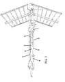
- antenna for radio - television signals according to the invention, totally indicated with the reference numeral 1 and comprising a central cradle 2 and two side cradles 3.
- Each cradle 2 and 3 or backbone is composed of a tubular element with predefined thickness and length made of a convenient metallic material, such as e.g. aluminium alloy with high mechanical strength, and it is provided with a plurality of transversal holes which are distributed along the longitudinal development of the tube.
- a convenient metallic material such as e.g. aluminium alloy with high mechanical strength
- the cradles 2 and 3 are coupled with respective antenna elements 4 and 5, which are composed essentially of pole - shaped elements with predefined length made of with a convenient metallic material, for example a wire in aluminium alloy with high mechanical strength.
- the antenna elements 4 and 5 may be fitted in a respective engagement area in corresponding holes made on cradles 2 and 3 so that to obtain a forced coupling according to practices known in the art, as on the other hand described in another patent of the same applicant.
- each antenna element 4 or 5 is passing through two coaxial holes with transversal axis provided on sides opposite to the tubular element constituting the respective coupling cradle 2 or 3 and then it presents two opposing lengths 4a and 4b or 5a and 5b protruding from said sides.
- the antenna 1 further comprises a joint totally indicated with the numeral 7, the so-called rear joint, which is assembled on cradles 2 and 3, as will be better explained hereinafter, at a middle length of the central cradle 2 and a length of the rear end of the side cradles 3.
- the joint 7 is provided with holes 8 crossed by an antenna element 4 of the central cradle 2 and with two antenna elements 5 of the respective side cradles 3 which are next to the lengths of the cradles 2 and 3 coupling with the joint 7.
- the central cradle 2 is substantially attached to the joint 7 and it may be connected by known means to the antenna support or pole (not shown).
- the side cradles 3 can be moved angularly, for a prearranged little angle, around the respective antenna elements 5 crossing the joint 7 (then acting substantially as rotation pins) and, in the operating use condition of the antenna 1 (shown in figures 4-6 ), the side cradles 3 are angularly spaced from the central cradle 2.
- the antenna 1 further comprises a locking bracket, totally indicated with numeral 9, also named front joint, which is combined with the cradles 2 and 3 at a middle front length of the central cradle 2 and at front end lengths of the side cradles 3.
- a locking bracket totally indicated with numeral 9, also named front joint, which is combined with the cradles 2 and 3 at a middle front length of the central cradle 2 and at front end lengths of the side cradles 3.
- the locking bracket 9 comprises two opposing and substantially bracket elements, precisely a first bracket element 10 and a second bracket element 11, assembled on opposed sides of the central cradle 2 and side cradles 3 and joined one another by interlocked connecting means hereinafter better explained.
- Each bracket element 10 and 11 comprises a substantially central and coaxial eyelet 12 crossed by an antenna element 4 of the central cradle 2, in particular by a length 4a and 4b, respectively, of said antenna element 4 protruding from the assembling side of the bracket element 10 and 11.
- both the bracket elements 10 and 11 are integral and rotating around the antenna elements 4 of the central cradle.
- the bracket elements 10 and 11 are rotatingly moving between a rest position in which the antenna 1 is folded (shown in figs. 1-3 ), i.e. with the side cradles 3 folded and substantially moved near the central cradle 2 and an operating condition of the antenna 1 (shown in figs. 3-6 ) in which on the contrary the side cradle 3 are angularly spaced from the central cradle 2 according to a prearranged angle.
- bracket elements 10 and 11 have hooking means removably engaging with the two respective pole - shaped elements 5 of the side cradles as said operating position is reached.
- these hooking means are, for each bracket elements 10 and 11, two substantially hook - shaped opposing ending portions and provided with open seats on opposite sides of both the bracket elements 10 and 11, in which respective antenna elements 5 of the side cradles 3 removably engage as the operating position of the antenna 1 is reached.
- the bracket element 10 of the locking bracket 9 has two hook - shaped opposing ending portions 10a and 10b provided with respective seats 13 open on opposed sides of the bracket element 10 and facing towards respective lengths 5a protruding from the same side of two respective antenna elements 5 of the side cradles 3.
- the bracket element 11 of the locking bracket 9 has two hook - shaped opposing ending portions 11a and 11b provided with respective seats 13 open on opposed sides of the bracket element 11 and facing towards respective lengths 5b of said respective antenna elements 5 of the side cradles 3, said lengths 5b being protruding from the side opposed to the side said lengths 5a are protruding from.
- the operating position is such that possible loads exercise a force substantially perpendicular to the disengaging direction of hooks and then accidental closures of installed antenna are avoided.
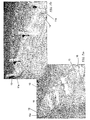
- bracket elements 10 and 11 are a plurality of pegs made as a whole on one of the bracket elements (in the specific case the bracket element 11 - fig. 7b ) engaging in corresponding holes provided on the other of the bracket element (in the specific case the bracket element 10 - fig. 7a ).
- Each peg 15 or 17 of the first bracket element 11 has, at the free end, at least one couple of elastically deformable fins 19 and shaped so that to obtain a substantially snap fitted coupling in respective holes 16 or 18 of the second bracket elements 10.
- the ending pegs 15 are located outside the side cradles 3 whereas the middle pegs 17 are located over said central cradle 2 so that the middle pegs 17 act substantially as dragging elements of the side cradles 3 during rotation of the locking bracket 9 around the antenna element 4 of the central cradle 2 crossing it from the folding position to the operating position (removal of the side cradles 3 from the central cradle 2) whereas the ending pegs 15 act as a limit stop for the angular movement of the side cradles 3 as the operating position is reached.
- the hooked - shaped ending portion 10a and 10b of the bracket element 10 engage the protruding lengths 5a of two respective antenna elements 5 of the side cradles 3 in seats 13, whereas the hook - shaped ending portions 11a and 11b of the opposing bracket element 11 engage the opposing protruding lengths 5b of said antenna elements 5 in seats 13.
- the side cradles 3 abut externally on the ending pegs 15 of the locking bracket 9, so that these ending pegs 15 constitute said limit stop for the removal movement of the side cradles 3 from the central cradle 2.
- the two bracket elements 10 and 11 are preferably both provided ( figs. 7a, 7b ) with a pin 10c, 11c, respectively, resulting aligned with their central eyelet 12 and designed for snap fitting in a corresponding hole 2c made in the central cradle 2 ( fig. 5 ).
- the rotation of the bracket 9 from the operating position to the folding position may be intentional only, carried out by an action and force intended for disengaging the bracket elements 10 and 11 from the respective antenna elements 5 of the side cradles 3, and the additional pins 10c, 11c from the holes of the central cradle.
- the ending pegs 15 act substantially as dragging elements of said side cradles 3
- the middle pegs 17 act as limit stop for the angular movement of the side cradles 3 as the folding position is reached.
- the side cradles 3 abut against the middle pegs 17 (constituting then said limit stop for the movement of the side cradles 3 towards the side cradle 2) and they are substantially moved near the central cradle 3.
- the joint 7 is made to be able too to be assembled on cradles without the need of screws.
- the joint 7 is composed of a box-shaped body comprising a higher shell 20 and a lower shell 21 connected one another and forming a substantially central seat 22 open on two opposing sides for the passage of the central cradle 2 and two side seats 23 open on only one of said sides for housing respective lengths of rear end of the side cradles 3.
- the higher shell 20 and the lower shell 21 are provided with opposing coaxial holes 8 for the passage of an antenna element 4 of the central cradle 2 and two antenna elements 5 of the respective side cradles 3 of the antenna 1.
- the side seats 23 are slightly flared towards the open side to allow the rotation of the side cradles 3 around the respective antenna elements 5 crossing the holes 8 inside a predetermined little angle.
- the higher shell 20 and the lower shell 21 are joined one another by interlocked, preferably snap fitted, coupling means.
- these means are a plurality of mushroom - shaped pegs 24, made as a whole both in the higher shell 20 and the lower shell 21 at the seat 22 for the central cradle 2, said pegs 24 of the higher shell 20 and the lower shell both having a couple of elastically deformable fins 25 snap fitting in corresponding coupling holes 26 made in the lower shell 21 and higher shell 20 respectively.
- the assembly of the joint 7 is particularly easy and simple and without the screw aids, being sufficient to assemble the higher shell 20 and the lower shell 21 on opposite sides of the cradles 2 and 3 and taking care the holes 8 are crossed by respective antenna elements 4 and 5 of said cradles 2 and 3 and then the shells 20 and 21 are joined by the snap fitting of the pegs 24 in respective holes 26.
- the higher shell 20 and the lower shell 21 may be also provided externally with tabs 27 with eyelet 28 interlocking with respective reliefs 29 formed on the lower shell 21 and the higher shell 20, respectively.
- the antenna 1 may be conveniently pre-assembled in the factory with an extremely efficient productive process with the joint 7 and the locking bracket 9 assembled yet on cradles 2 and 3 and packaged in the folded position which guarantees the minimum bulk.
- the installation of the antenna 1 according to the invention may be carried out easily by means of unskilled persons.
Landscapes
- Engineering & Computer Science (AREA)
- Multimedia (AREA)
- Signal Processing (AREA)
- Support Of Aerials (AREA)
Claims (11)
- Antenne (1) für Radio- und Fernsehsignale des Typs umfassend einen Zentralträger (2) und einen, zwei oder mehr Seitenträger (3), die relativ zum besagten Zentralträger (2) an einem Hintergelenk (7) schwenkbar sind, wobei jeder Träger (2; 3) aus einem mit über die Längsausdehnung verteilten Öffnungen versehenen rohrförmigen Element besteht, eine Vielzahl von polförmigen Elementen (4; 5), die an den rohrförmigen Elementen des Zentralträgers (2) und des/der Seitenträgers/Seitenträger (3) angeschlossen sind, und einen Verriegelungsbügel (9) zum Halten der besagten Träger (2, 3) mit den entsprechenden polförmigen Elementen (4; 5) in einer Betriebsstellung, in welcher jeder Seitenträger (3) sich in einem Winkelabstand zu dem Zentralträger (2) befindet, wobei die besagte Antenne (1) dadurch gekennzeichnet ist, dass der besagte Verriegelungsbügel (9) um ein polförmiges Element (4) des Zentralträgers (2), zwischen einer Faltstellung, in welcher jeder einzelne Seitenträger (3) im Wesentlichen in der Nähe des Zentralträgers (2) verschoben ist, und der besagten Betriebsstellung verschwenkbar ist, wobei der besagte Verriegelungsbügel (9) auch Hakenmittel aufweist (10a, 10b, 11a, 11b), die bei Erreichung der besagten Betriebsstellung lösbar in den entsprechenden polförmigen Elementen (5) jedes Seitenträgers (3) eingreifen.
- Antenne (1) nach Anspruch 1, wobei der besagte Montagebügel (9) ein erstes Bügelelement (10) und ein zweites Bügelelement (11) umfasst, die auf gegenüberliegenden Seiten des besagten Zentralträgers (2) und jedes Seitenträgers (3) angebracht und miteinander verbunden sind, wobei das besagte erste Bügelelement (10) und das besagte zweite Bügelelement (11) mit im Wesentlichen zentralen und einander koaxialen Ösen (12) versehen sind, die von einem polförmigen Element (4) des Zentralträgers (2) durchquert werden.
- Antenne (1) nach Anspruch 2, wobei die besagten Hakenmittel (10a, 10b; 11a, 11b) umfassen, für jeweils das erste Bügelelement (10) oder das zweite Bügelelement (11), mindestens einen im Wesentlichen hakenförmigen Endabschnitt, der mit entsprechenden Aufnahmen (13) versehen ist, die auf gegenüberliegenden Seiten des jeweiligen ersten Bügelelementes (10) oder zweiten Bügelelementes (11) geöffnet sind und in die bei Erreichung der besagten Betriebsstellung jeweils ein polförmiges Element (5) einer der besagten Seitenträger (3) lösbar eingreift.
- Antenne (1) nach Anspruch 2 oder 3, wobei das besagte erste Bügelelement (10) und das besagte zweite Bügelelement (11) durch ineinander gerastete, bevorzugt ineinander eingeschnappte Kupplungsmittel miteinander verbunden sind.
- Antenne (1) nach Anspruch 4, wobei die besagten ineinander gerasteten Kupplungsmittel umfassen eine Vielzahl von Zapfen (15, 17), die mit einem (11) der besagten Bügelelemente (10, 11) ausgebildet sind und in entsprechende in dem anderen (10) der besagten Bügelelemente (10, 11) gebildete Löcher (16, 18) eingreifen.
- Antenne (1) nach Anspruch 5, wobei die besagte Vielzahl von Zapfen Endzapfen (15) umfasst, die im Wesentlichen an den Enden der besagten hakenförmigen Abschnitte (11a, 11b) geformt sind, und Mittelzapfen (17), die aus gegenüberliegenden Seiten bezüglich der besagten Öse (12) geformt sind, und die besagten Endzapfen (15) außerhalb des jeweiligen Seitenträgers (3) positioniert sind und die besagten Mittelzapfen (17) auf gegenüberliegenden Seiten bezüglich des besagten Zentralträgers (2) so angeordnet sind, dass die besagten Mittelzapfen (17) den/die besagten Seitenträger (3) bei der Drehung des besagten Verriegelungsbügels (9) von der besagten Faltstellung zur besagten Betriebsstellung im Wesentlichen mitnehmen, während die Endzapfen (15) als Begrenzungsanschlag für die Schwenkbewegung der/des Seitenträger/s (3) bei Erreichung der Betriebsstellung dienen und umgekehrt die besagten Endzapfen (15) den/die besagten Seitenträger (3) bei der Drehung des besagten Verriegelungsbügels (9) von der besagten Betriebsstellung zur besagten Faltstellung im Wesentlichen mitnehmen, während die besagten Mittelzapfen (17) als Begrenzungsanschlag für die Schwenkbewegung der/des Seitenträger/s (3) bei Erreichung der Faltstellung dienen.
- Antenne nach einem der vorhergehenden Ansprüche 4 - 6, wobei das besagte erste Bügelelement (10) und das besagte zweite Bügelelement (11) jeweils einen zusätzlichen Stift (10c, 11c) aufweisen, der zum Eingreifen in ein entsprechendes, im Zentralträger (2) vorgesehenes Loch (2c) eingerichtet ist, wenn der Verriegelungsbügel sich in der Betriebsstellung befindet, wobei der zusätzliche Stift mit der Öse (12) des entsprechenden Bügels fluchtet.
- Antenne (1) nach einem der vorhergehenden Ansprüche, wobei das besagte Gelenk (7) aus einem kastenförmigen Körper besteht, umfassend eine obere Schale (20) und eine untere Schale (21), die mit gegenüberliegenden koaxialen Löchern (8) versehen sind, zum Hindurchführen eines polförmigen Elementes (4) des besagten Zentralträgers (2) und eines polförmigen Elementes (5) jedes Seitenträgers (3), wobei die besagte obere Schale (20) und die besagte untere Schale (21) im Wesentlichen einen Zentralsitz (22), zum Durchgang des besagten Zentralträgers (2), und ein, zwei oder mehr Seitensitze (23) zum Aufnehmen jeweils einer entsprechenden Länge des Hinterendes eines Seitenträgers (3) bilden und durch ineinander gerastete, bevorzugt ineinander eingeschnappte Kupplungsmittel miteinander verbunden sind.
- Antenne (1) nach Anspruch 8, wobei die besagten Kupplungsmittel umfassen:- eine Vielzahl von Zapfen (24), die mit der oberen Schale (20) und/oder mit der unteren Schale (21) einstückig ausgebildet sind und vorzugsweise in entsprechende, in der unteren Schale (21) und/oder oberen Schale (20) geformten Kupplungslöcher (26) eingeschnappt sind und fallweise- eine Vielzahl von Laschen (27) mit Aussparung (28), die mit der Außenseite der oberen Schale (20) und/oder der unteren Schale (21) einstückig ausgebildet sind und mit entsprechenden, auf der unteren Schale (21) und/oder oberen Schale (20) gebildeten Erhöhungen (29) eingerastet sind.
- Verriegelungsbügel (9) für eine Antenne (1) nach einem der vorhergehenden Ansprüche, umfassend ein erstes Bügelelement (10) und ein zweites Bügelelement (11), die bei Benutzung vorzugsweise durch ineinander gerastete Kupplungsmittel miteinander verbunden sind, wobei das besagte erste Bügelelement (10) und das besagte zweite Bügelelement (11) jeweils mit im Wesentlichen zentralen und koaxialen Ösen (12) zum Durchgang des polförmigen Elementes (4) des Zentralträgers (2) der besagten Antenne (1) versehen sind und ein, zwei oder mehr im Wesentlichen hakenförmige Endabschnitte (10a, 10b; 11a, 11b) aufweisen, die mit entsprechenden Aufnahmen (13) versehen sind, welche auf gegenüberliegenden Seiten des jeweiligen ersten Bügelelementes (10) oder zweiten Bügelelementes (11) geöffnet sind und zum lösbaren Eingriff mit jeweiligen polförmigen Elementen (5) des entsprechenden Seitenträgers (3) bei Erreichung der Betriebsstellung der besagten Antenne (1) vorgesehen sind.
- Antenne (1) nach einem der vorhergehenden Ansprüche 1 - 8, umfassend ein mit einer oberen Schale (20) und einer unteren Schale (21) versehenes Gelenk (7), das gegenüberliegende koaxiale Löcher (8), zum Hindurchführen eines polförmigen Elementes (4) des Zentralträgers (1) der besagten Antenne (1) und ein, zwei oder mehr polförmige Elemente (5) jeweils eines entsprechenden Seitenträgers (3) aufweist, wobei die besagte obere Schale (20) und die besagte untere Schale (21) im Wesentlichen einen Zentralsitz (22), zum Durchgang des besagten Zentralträgers (2), und ein, zwei oder mehr Seitensitze (23), jeweils zum Aufnehmen einer entsprechenden Länge des Endes der entsprechenden Seitenträger (3) bilden und durch ineinander gerastete, bevorzugt ineinander eingeschnappte Kupplungsmittel miteinander verbunden sind.
Priority Applications (1)
| Application Number | Priority Date | Filing Date | Title |
|---|---|---|---|
| SI201230014T SI2495812T1 (sl) | 2011-03-01 | 2012-02-27 | Televizijska antena z veäśimi oporami |
Applications Claiming Priority (1)
| Application Number | Priority Date | Filing Date | Title |
|---|---|---|---|
| IT000024A ITBS20110024A1 (it) | 2011-03-01 | 2011-03-01 | Antenna televisiva a piu' culle |
Publications (2)
| Publication Number | Publication Date |
|---|---|
| EP2495812A1 EP2495812A1 (de) | 2012-09-05 |
| EP2495812B1 true EP2495812B1 (de) | 2013-10-16 |
Family
ID=43976893
Family Applications (1)
| Application Number | Title | Priority Date | Filing Date |
|---|---|---|---|
| EP20120157101 Active EP2495812B1 (de) | 2011-03-01 | 2012-02-27 | Fernsehantenne mit mehreren Armen |
Country Status (5)
| Country | Link |
|---|---|
| EP (1) | EP2495812B1 (de) |
| ES (1) | ES2439720T3 (de) |
| IT (1) | ITBS20110024A1 (de) |
| PT (1) | PT2495812E (de) |
| SI (1) | SI2495812T1 (de) |
Families Citing this family (1)
| Publication number | Priority date | Publication date | Assignee | Title |
|---|---|---|---|---|
| EP2858178B1 (de) * | 2013-10-03 | 2016-11-09 | Televés, S.A. | Antenne und Verfahren zum Empfang von Telekommunikationssignalen |
Family Cites Families (4)
| Publication number | Priority date | Publication date | Assignee | Title |
|---|---|---|---|---|
| ATE360270T1 (de) * | 2000-09-29 | 2007-05-15 | Televes Sa | Antenne |
| CN201336367Y (zh) * | 2009-02-16 | 2009-10-28 | 张伟强 | 一种天线多方向引向器 |
| CN201682043U (zh) * | 2010-04-15 | 2010-12-22 | 杨瑞典 | 引向器可收放调节的室外天线 |
| CN201717355U (zh) * | 2010-04-15 | 2011-01-19 | 杨瑞典 | 可伸缩调节的室外天线 |
-
2011
- 2011-03-01 IT IT000024A patent/ITBS20110024A1/it unknown
-
2012
- 2012-02-27 SI SI201230014T patent/SI2495812T1/sl unknown
- 2012-02-27 ES ES12157101T patent/ES2439720T3/es active Active
- 2012-02-27 PT PT12157101T patent/PT2495812E/pt unknown
- 2012-02-27 EP EP20120157101 patent/EP2495812B1/de active Active
Also Published As
| Publication number | Publication date |
|---|---|
| ES2439720T3 (es) | 2014-01-24 |
| PT2495812E (pt) | 2013-12-26 |
| SI2495812T1 (sl) | 2014-04-30 |
| ITBS20110024A1 (it) | 2012-09-02 |
| EP2495812A1 (de) | 2012-09-05 |
Similar Documents
| Publication | Publication Date | Title |
|---|---|---|
| US20200315306A1 (en) | Quick assembly methods and components for shade structures | |
| CN102014684B (zh) | 公按扣和母按扣 | |
| US8166605B2 (en) | Windshield wiper arm bracket | |
| CA2926137C (en) | False ceiling suspension system, profile and method | |
| US6354702B2 (en) | Support for auxiliary lenses for use with eyeglasses | |
| US6237169B1 (en) | Foldable trampoline | |
| US9718076B2 (en) | Sprinkler side frame coupling device | |
| US20160198847A1 (en) | Structure of coupling sleeve of storage shelf | |
| EP2213193A2 (de) | Einstellbare Rippenverbinder | |
| US7509712B2 (en) | Device for the connection of a band to a further part | |
| WO2014089496A2 (en) | Canopy shelter link point | |
| KR102660872B1 (ko) | 안테나용 클램핑 장치 | |
| EP2495812B1 (de) | Fernsehantenne mit mehreren Armen | |
| TW200905055A (en) | Hanger | |
| CN105377207A (zh) | 用于将辅助元件连接至轮椅的系统 | |
| CN109720539A (zh) | 航空器框架组件、航空器结构框架和航空器 | |
| EP3047763B1 (de) | Vorhangzubehör | |
| EP3187788B1 (de) | Rohrbefestigungsstruktur | |
| KR101479966B1 (ko) | 다단형으로 조립이 가능한 돔형 텐트 프레임 | |
| TWI594710B (zh) | Folding umbrella anti-flip umbrella structure | |
| KR20180090557A (ko) | 락킹기능이 개선된 원터치 텐트 | |
| TW201300041A (zh) | 適用於鐘錶錶帶之扣件 | |
| WO2016201112A1 (en) | Multi-piece bezel for electro-optic window assembly | |
| US4916786A (en) | Method of assembling an armature of an umbrella | |
| EP3772559B1 (de) | Verankerungssystem mit diagonalaussteifung und schalungsstrebe |
Legal Events
| Date | Code | Title | Description |
|---|---|---|---|
| PUAI | Public reference made under article 153(3) epc to a published international application that has entered the european phase |
Free format text: ORIGINAL CODE: 0009012 |
|
| AK | Designated contracting states |
Kind code of ref document: A1 Designated state(s): AL AT BE BG CH CY CZ DE DK EE ES FI FR GB GR HR HU IE IS IT LI LT LU LV MC MK MT NL NO PL PT RO RS SE SI SK SM TR |
|
| AX | Request for extension of the european patent |
Extension state: BA ME |
|
| 17P | Request for examination filed |
Effective date: 20120903 |
|
| GRAP | Despatch of communication of intention to grant a patent |
Free format text: ORIGINAL CODE: EPIDOSNIGR1 |
|
| RIC1 | Information provided on ipc code assigned before grant |
Ipc: H01Q 19/30 20060101ALI20130523BHEP Ipc: H01Q 1/08 20060101ALI20130523BHEP Ipc: H01Q 9/12 20060101AFI20130523BHEP Ipc: H04N 5/64 20060101ALI20130523BHEP Ipc: H01Q 19/04 20060101ALI20130523BHEP Ipc: H01Q 1/12 20060101ALI20130523BHEP |
|
| INTG | Intention to grant announced |
Effective date: 20130617 |
|
| GRAS | Grant fee paid |
Free format text: ORIGINAL CODE: EPIDOSNIGR3 |
|
| GRAA | (expected) grant |
Free format text: ORIGINAL CODE: 0009210 |
|
| AK | Designated contracting states |
Kind code of ref document: B1 Designated state(s): AL AT BE BG CH CY CZ DE DK EE ES FI FR GB GR HR HU IE IS IT LI LT LU LV MC MK MT NL NO PL PT RO RS SE SI SK SM TR |
|
| REG | Reference to a national code |
Ref country code: GB Ref legal event code: FG4D |
|
| REG | Reference to a national code |
Ref country code: CH Ref legal event code: EP |
|
| REG | Reference to a national code |
Ref country code: IE Ref legal event code: FG4D |
|
| REG | Reference to a national code |
Ref country code: AT Ref legal event code: REF Ref document number: 636888 Country of ref document: AT Kind code of ref document: T Effective date: 20131115 |
|
| REG | Reference to a national code |
Ref country code: DE Ref legal event code: R096 Ref document number: 602012000383 Country of ref document: DE Effective date: 20131219 |
|
| REG | Reference to a national code |
Ref country code: PT Ref legal event code: SC4A Free format text: AVAILABILITY OF NATIONAL TRANSLATION Effective date: 20131213 |
|
| REG | Reference to a national code |
Ref country code: ES Ref legal event code: FG2A Ref document number: 2439720 Country of ref document: ES Kind code of ref document: T3 Effective date: 20140124 |
|
| REG | Reference to a national code |
Ref country code: NL Ref legal event code: VDEP Effective date: 20131016 |
|
| REG | Reference to a national code |
Ref country code: AT Ref legal event code: MK05 Ref document number: 636888 Country of ref document: AT Kind code of ref document: T Effective date: 20131016 |
|
| REG | Reference to a national code |
Ref country code: LT Ref legal event code: MG4D |
|
| PG25 | Lapsed in a contracting state [announced via postgrant information from national office to epo] |
Ref country code: IS Free format text: LAPSE BECAUSE OF FAILURE TO SUBMIT A TRANSLATION OF THE DESCRIPTION OR TO PAY THE FEE WITHIN THE PRESCRIBED TIME-LIMIT Effective date: 20140216 Ref country code: NL Free format text: LAPSE BECAUSE OF FAILURE TO SUBMIT A TRANSLATION OF THE DESCRIPTION OR TO PAY THE FEE WITHIN THE PRESCRIBED TIME-LIMIT Effective date: 20131016 Ref country code: SE Free format text: LAPSE BECAUSE OF FAILURE TO SUBMIT A TRANSLATION OF THE DESCRIPTION OR TO PAY THE FEE WITHIN THE PRESCRIBED TIME-LIMIT Effective date: 20131016 Ref country code: NO Free format text: LAPSE BECAUSE OF FAILURE TO SUBMIT A TRANSLATION OF THE DESCRIPTION OR TO PAY THE FEE WITHIN THE PRESCRIBED TIME-LIMIT Effective date: 20140116 Ref country code: BE Free format text: LAPSE BECAUSE OF FAILURE TO SUBMIT A TRANSLATION OF THE DESCRIPTION OR TO PAY THE FEE WITHIN THE PRESCRIBED TIME-LIMIT Effective date: 20131016 Ref country code: LT Free format text: LAPSE BECAUSE OF FAILURE TO SUBMIT A TRANSLATION OF THE DESCRIPTION OR TO PAY THE FEE WITHIN THE PRESCRIBED TIME-LIMIT Effective date: 20131016 Ref country code: HR Free format text: LAPSE BECAUSE OF FAILURE TO SUBMIT A TRANSLATION OF THE DESCRIPTION OR TO PAY THE FEE WITHIN THE PRESCRIBED TIME-LIMIT Effective date: 20131016 |
|
| PG25 | Lapsed in a contracting state [announced via postgrant information from national office to epo] |
Ref country code: AT Free format text: LAPSE BECAUSE OF FAILURE TO SUBMIT A TRANSLATION OF THE DESCRIPTION OR TO PAY THE FEE WITHIN THE PRESCRIBED TIME-LIMIT Effective date: 20131016 Ref country code: RS Free format text: LAPSE BECAUSE OF FAILURE TO SUBMIT A TRANSLATION OF THE DESCRIPTION OR TO PAY THE FEE WITHIN THE PRESCRIBED TIME-LIMIT Effective date: 20131016 Ref country code: LV Free format text: LAPSE BECAUSE OF FAILURE TO SUBMIT A TRANSLATION OF THE DESCRIPTION OR TO PAY THE FEE WITHIN THE PRESCRIBED TIME-LIMIT Effective date: 20131016 Ref country code: CY Free format text: LAPSE BECAUSE OF FAILURE TO SUBMIT A TRANSLATION OF THE DESCRIPTION OR TO PAY THE FEE WITHIN THE PRESCRIBED TIME-LIMIT Effective date: 20131016 |
|
| REG | Reference to a national code |
Ref country code: DE Ref legal event code: R097 Ref document number: 602012000383 Country of ref document: DE |
|
| PG25 | Lapsed in a contracting state [announced via postgrant information from national office to epo] |
Ref country code: EE Free format text: LAPSE BECAUSE OF FAILURE TO SUBMIT A TRANSLATION OF THE DESCRIPTION OR TO PAY THE FEE WITHIN THE PRESCRIBED TIME-LIMIT Effective date: 20131016 |
|
| PLBE | No opposition filed within time limit |
Free format text: ORIGINAL CODE: 0009261 |
|
| STAA | Information on the status of an ep patent application or granted ep patent |
Free format text: STATUS: NO OPPOSITION FILED WITHIN TIME LIMIT |
|
| PG25 | Lapsed in a contracting state [announced via postgrant information from national office to epo] |
Ref country code: PL Free format text: LAPSE BECAUSE OF FAILURE TO SUBMIT A TRANSLATION OF THE DESCRIPTION OR TO PAY THE FEE WITHIN THE PRESCRIBED TIME-LIMIT Effective date: 20131016 Ref country code: IT Free format text: LAPSE BECAUSE OF FAILURE TO SUBMIT A TRANSLATION OF THE DESCRIPTION OR TO PAY THE FEE WITHIN THE PRESCRIBED TIME-LIMIT Effective date: 20131016 Ref country code: RO Free format text: LAPSE BECAUSE OF FAILURE TO SUBMIT A TRANSLATION OF THE DESCRIPTION OR TO PAY THE FEE WITHIN THE PRESCRIBED TIME-LIMIT Effective date: 20131016 Ref country code: SK Free format text: LAPSE BECAUSE OF FAILURE TO SUBMIT A TRANSLATION OF THE DESCRIPTION OR TO PAY THE FEE WITHIN THE PRESCRIBED TIME-LIMIT Effective date: 20131016 Ref country code: CZ Free format text: LAPSE BECAUSE OF FAILURE TO SUBMIT A TRANSLATION OF THE DESCRIPTION OR TO PAY THE FEE WITHIN THE PRESCRIBED TIME-LIMIT Effective date: 20131016 |
|
| REG | Reference to a national code |
Ref country code: DE Ref legal event code: R119 Ref document number: 602012000383 Country of ref document: DE |
|
| 26N | No opposition filed |
Effective date: 20140717 |
|
| PG25 | Lapsed in a contracting state [announced via postgrant information from national office to epo] |
Ref country code: DK Free format text: LAPSE BECAUSE OF FAILURE TO SUBMIT A TRANSLATION OF THE DESCRIPTION OR TO PAY THE FEE WITHIN THE PRESCRIBED TIME-LIMIT Effective date: 20131016 Ref country code: LU Free format text: LAPSE BECAUSE OF FAILURE TO SUBMIT A TRANSLATION OF THE DESCRIPTION OR TO PAY THE FEE WITHIN THE PRESCRIBED TIME-LIMIT Effective date: 20140227 Ref country code: MC Free format text: LAPSE BECAUSE OF FAILURE TO SUBMIT A TRANSLATION OF THE DESCRIPTION OR TO PAY THE FEE WITHIN THE PRESCRIBED TIME-LIMIT Effective date: 20131016 |
|
| REG | Reference to a national code |
Ref country code: DE Ref legal event code: R097 Ref document number: 602012000383 Country of ref document: DE Effective date: 20140717 |
|
| REG | Reference to a national code |
Ref country code: DE Ref legal event code: R119 Ref document number: 602012000383 Country of ref document: DE Effective date: 20140902 |
|
| REG | Reference to a national code |
Ref country code: IE Ref legal event code: MM4A |
|
| PG25 | Lapsed in a contracting state [announced via postgrant information from national office to epo] |
Ref country code: DE Free format text: LAPSE BECAUSE OF NON-PAYMENT OF DUE FEES Effective date: 20140902 Ref country code: IE Free format text: LAPSE BECAUSE OF NON-PAYMENT OF DUE FEES Effective date: 20140227 |
|
| PGFP | Annual fee paid to national office [announced via postgrant information from national office to epo] |
Ref country code: SI Payment date: 20150128 Year of fee payment: 4 |
|
| REG | Reference to a national code |
Ref country code: CH Ref legal event code: PL |
|
| PG25 | Lapsed in a contracting state [announced via postgrant information from national office to epo] |
Ref country code: LI Free format text: LAPSE BECAUSE OF NON-PAYMENT OF DUE FEES Effective date: 20150228 Ref country code: CH Free format text: LAPSE BECAUSE OF NON-PAYMENT OF DUE FEES Effective date: 20150228 |
|
| REG | Reference to a national code |
Ref country code: FR Ref legal event code: PLFP Year of fee payment: 5 |
|
| PG25 | Lapsed in a contracting state [announced via postgrant information from national office to epo] |
Ref country code: MT Free format text: LAPSE BECAUSE OF FAILURE TO SUBMIT A TRANSLATION OF THE DESCRIPTION OR TO PAY THE FEE WITHIN THE PRESCRIBED TIME-LIMIT Effective date: 20131016 |
|
| PG25 | Lapsed in a contracting state [announced via postgrant information from national office to epo] |
Ref country code: SM Free format text: LAPSE BECAUSE OF FAILURE TO SUBMIT A TRANSLATION OF THE DESCRIPTION OR TO PAY THE FEE WITHIN THE PRESCRIBED TIME-LIMIT Effective date: 20131016 |
|
| PG25 | Lapsed in a contracting state [announced via postgrant information from national office to epo] |
Ref country code: BG Free format text: LAPSE BECAUSE OF FAILURE TO SUBMIT A TRANSLATION OF THE DESCRIPTION OR TO PAY THE FEE WITHIN THE PRESCRIBED TIME-LIMIT Effective date: 20131016 Ref country code: GR Free format text: LAPSE BECAUSE OF FAILURE TO SUBMIT A TRANSLATION OF THE DESCRIPTION OR TO PAY THE FEE WITHIN THE PRESCRIBED TIME-LIMIT Effective date: 20140117 |
|
| PG25 | Lapsed in a contracting state [announced via postgrant information from national office to epo] |
Ref country code: TR Free format text: LAPSE BECAUSE OF FAILURE TO SUBMIT A TRANSLATION OF THE DESCRIPTION OR TO PAY THE FEE WITHIN THE PRESCRIBED TIME-LIMIT Effective date: 20131016 Ref country code: HU Free format text: LAPSE BECAUSE OF FAILURE TO SUBMIT A TRANSLATION OF THE DESCRIPTION OR TO PAY THE FEE WITHIN THE PRESCRIBED TIME-LIMIT; INVALID AB INITIO Effective date: 20120227 |
|
| GBPC | Gb: european patent ceased through non-payment of renewal fee |
Effective date: 20160227 |
|
| PG25 | Lapsed in a contracting state [announced via postgrant information from national office to epo] |
Ref country code: SI Free format text: LAPSE BECAUSE OF NON-PAYMENT OF DUE FEES Effective date: 20160228 |
|
| REG | Reference to a national code |
Ref country code: SI Ref legal event code: KO00 Effective date: 20161013 |
|
| REG | Reference to a national code |
Ref country code: FR Ref legal event code: PLFP Year of fee payment: 6 |
|
| PG25 | Lapsed in a contracting state [announced via postgrant information from national office to epo] |
Ref country code: GB Free format text: LAPSE BECAUSE OF NON-PAYMENT OF DUE FEES Effective date: 20160227 |
|
| REG | Reference to a national code |
Ref country code: FR Ref legal event code: PLFP Year of fee payment: 7 |
|
| PG25 | Lapsed in a contracting state [announced via postgrant information from national office to epo] |
Ref country code: MK Free format text: LAPSE BECAUSE OF FAILURE TO SUBMIT A TRANSLATION OF THE DESCRIPTION OR TO PAY THE FEE WITHIN THE PRESCRIBED TIME-LIMIT Effective date: 20131016 |
|
| PG25 | Lapsed in a contracting state [announced via postgrant information from national office to epo] |
Ref country code: AL Free format text: LAPSE BECAUSE OF FAILURE TO SUBMIT A TRANSLATION OF THE DESCRIPTION OR TO PAY THE FEE WITHIN THE PRESCRIBED TIME-LIMIT Effective date: 20131016 |
|
| PGFP | Annual fee paid to national office [announced via postgrant information from national office to epo] |
Ref country code: GB Payment date: 20190315 Year of fee payment: 13 |
|
| PGFP | Annual fee paid to national office [announced via postgrant information from national office to epo] |
Ref country code: PT Payment date: 20190131 Year of fee payment: 8 |
|
| REG | Reference to a national code |
Ref country code: FI Ref legal event code: MAE |
|
| PG25 | Lapsed in a contracting state [announced via postgrant information from national office to epo] |
Ref country code: FI Free format text: LAPSE BECAUSE OF NON-PAYMENT OF DUE FEES Effective date: 20200227 Ref country code: PT Free format text: LAPSE BECAUSE OF NON-PAYMENT OF DUE FEES Effective date: 20200929 |
|
| PGFP | Annual fee paid to national office [announced via postgrant information from national office to epo] |
Ref country code: ES Payment date: 20260304 Year of fee payment: 15 |
|
| PGFP | Annual fee paid to national office [announced via postgrant information from national office to epo] |
Ref country code: FR Payment date: 20260109 Year of fee payment: 15 |