EP2495807B1 - Mehrbandantenne - Google Patents
Mehrbandantenne Download PDFInfo
- Publication number
- EP2495807B1 EP2495807B1 EP11250242.2A EP11250242A EP2495807B1 EP 2495807 B1 EP2495807 B1 EP 2495807B1 EP 11250242 A EP11250242 A EP 11250242A EP 2495807 B1 EP2495807 B1 EP 2495807B1
- Authority
- EP
- European Patent Office
- Prior art keywords
- conductive plate
- antenna
- conductive
- substrate
- ground plane
- Prior art date
- Legal status (The legal status is an assumption and is not a legal conclusion. Google has not performed a legal analysis and makes no representation as to the accuracy of the status listed.)
- Active
Links
- 239000000758 substrate Substances 0.000 claims description 35
- 239000004020 conductor Substances 0.000 claims description 34
- 241000251730 Chondrichthyes Species 0.000 description 16
- 230000008878 coupling Effects 0.000 description 13
- 238000010168 coupling process Methods 0.000 description 13
- 238000005859 coupling reaction Methods 0.000 description 13
- 230000005855 radiation Effects 0.000 description 10
- 238000004891 communication Methods 0.000 description 7
- 239000000463 material Substances 0.000 description 5
- 230000005404 monopole Effects 0.000 description 5
- RYGMFSIKBFXOCR-UHFFFAOYSA-N Copper Chemical compound [Cu] RYGMFSIKBFXOCR-UHFFFAOYSA-N 0.000 description 2
- 239000003990 capacitor Substances 0.000 description 2
- 230000010267 cellular communication Effects 0.000 description 2
- 239000002131 composite material Substances 0.000 description 2
- 238000010276 construction Methods 0.000 description 2
- 229910052802 copper Inorganic materials 0.000 description 2
- 239000010949 copper Substances 0.000 description 2
- 238000004519 manufacturing process Methods 0.000 description 2
- 239000004593 Epoxy Substances 0.000 description 1
- 230000009286 beneficial effect Effects 0.000 description 1
- 230000005540 biological transmission Effects 0.000 description 1
- 230000015556 catabolic process Effects 0.000 description 1
- 230000001413 cellular effect Effects 0.000 description 1
- 238000006731 degradation reaction Methods 0.000 description 1
- 230000001419 dependent effect Effects 0.000 description 1
- 239000003989 dielectric material Substances 0.000 description 1
- 230000009977 dual effect Effects 0.000 description 1
- 230000000694 effects Effects 0.000 description 1
- 230000005672 electromagnetic field Effects 0.000 description 1
- 238000005516 engineering process Methods 0.000 description 1
- 238000005530 etching Methods 0.000 description 1
- 238000005562 fading Methods 0.000 description 1
- 239000011521 glass Substances 0.000 description 1
- 238000002955 isolation Methods 0.000 description 1
- 239000010410 layer Substances 0.000 description 1
- 238000000034 method Methods 0.000 description 1
- 230000003647 oxidation Effects 0.000 description 1
- 238000007254 oxidation reaction Methods 0.000 description 1
- 239000011241 protective layer Substances 0.000 description 1
- 230000004044 response Effects 0.000 description 1
- 230000035945 sensitivity Effects 0.000 description 1
- 230000035939 shock Effects 0.000 description 1
Images


Classifications
-
- H—ELECTRICITY
- H01—ELECTRIC ELEMENTS
- H01Q—ANTENNAS, i.e. RADIO AERIALS
- H01Q1/00—Details of, or arrangements associated with, antennas
- H01Q1/27—Adaptation for use in or on movable bodies
- H01Q1/32—Adaptation for use in or on road or rail vehicles
- H01Q1/325—Adaptation for use in or on road or rail vehicles characterised by the location of the antenna on the vehicle
- H01Q1/3275—Adaptation for use in or on road or rail vehicles characterised by the location of the antenna on the vehicle mounted on a horizontal surface of the vehicle, e.g. on roof, hood, trunk
-
- H—ELECTRICITY
- H01—ELECTRIC ELEMENTS
- H01Q—ANTENNAS, i.e. RADIO AERIALS
- H01Q1/00—Details of, or arrangements associated with, antennas
- H01Q1/36—Structural form of radiating elements, e.g. cone, spiral, umbrella; Particular materials used therewith
- H01Q1/38—Structural form of radiating elements, e.g. cone, spiral, umbrella; Particular materials used therewith formed by a conductive layer on an insulating support
-
- H—ELECTRICITY
- H01—ELECTRIC ELEMENTS
- H01Q—ANTENNAS, i.e. RADIO AERIALS
- H01Q21/00—Antenna arrays or systems
- H01Q21/30—Combinations of separate antenna units operating in different wavebands and connected to a common feeder system
-
- H—ELECTRICITY
- H01—ELECTRIC ELEMENTS
- H01Q—ANTENNAS, i.e. RADIO AERIALS
- H01Q5/00—Arrangements for simultaneous operation of antennas on two or more different wavebands, e.g. dual-band or multi-band arrangements
- H01Q5/30—Arrangements for providing operation on different wavebands
- H01Q5/307—Individual or coupled radiating elements, each element being fed in an unspecified way
- H01Q5/342—Individual or coupled radiating elements, each element being fed in an unspecified way for different propagation modes
- H01Q5/357—Individual or coupled radiating elements, each element being fed in an unspecified way for different propagation modes using a single feed point
- H01Q5/364—Creating multiple current paths
- H01Q5/371—Branching current paths
-
- H—ELECTRICITY
- H01—ELECTRIC ELEMENTS
- H01Q—ANTENNAS, i.e. RADIO AERIALS
- H01Q9/00—Electrically-short antennas having dimensions not more than twice the operating wavelength and consisting of conductive active radiating elements
- H01Q9/04—Resonant antennas
- H01Q9/30—Resonant antennas with feed to end of elongated active element, e.g. unipole
- H01Q9/32—Vertical arrangement of element
- H01Q9/38—Vertical arrangement of element with counterpoise
Definitions
- the present disclosure relates to the field of multiband antennas, in particular, although not exclusively, to a compact multiband antenna for transmitting signals from, and receiving signals at, an automobile in a plurality of frequency bands.
- a shark fin unit may be positioned on the back of the roof top of a car.
- US 4395713 describes a transit antenna in which a grounded base is provided.
- a housing is mounted on the base.
- the chamber and base define a chamber.
- a substrate is fixed to the base.
- the housing and substrate have interconnected surfaces to maintain the substrate in substantially fixed orientation with respect to the base.
- Capacitively coupled antenna layers are in opposite faces of the substrate.
- JP 2003 133838 A describes a monopole antenna.
- first and second radiation conductors where lengthwise dimensions are slightly different are provided along upper and lower directions. Then, a signal at the same frequency is supplied to each feeder point of the pair of radiation conductors, thus resonating to a radio wave having a wavelength corresponding to the length of each of the radiation conductors and hence expanding a resonance frequency band.
- Such an antenna can be suitable for sending and receiving signals with frequencies of about 2.5 GHz and in excess of 5 GHz in the presence of the ground plane, and have a physical size that is suitable for fitting within the constraints of a known shark fin unit for an automobile.
- the shark fin unit When the shark fin unit is located on the rooftop of a vehicle, the vehicle can be considered as an extension of the ground plane, and therefore it can be important that the antenna is operable in the presence of such a large grounding body.
- the first and second conductive plates extend away from the ground plane in longitudinal direction.
- the length of the first and second conductive plates in the longitudinal direction may define the frequencies of signals that the plates are configured to transmit and receive.
- the length of the first and second conductive plates in the longitudinal direction corresponds to quarter wavelength monopole antennas for the frequencies of signals that the plates are configured to transmit and receive.
- the ground plane can be a bottom plate of the shark fin unit and the longitudinally extending conductive plates can extend vertically within the shark fin housing.
- the proportion of the first conductive plate that overlaps the second conductive plate may differ from the proportion of the second conductive plate that overlaps the first conductive plate by at least 5 %, 10 %, 15% or 20%. In this way, the amount of capacitive coupling between the two conductive plates can be limited so that the antenna can still operate satisfactorily in the presence of a large grounding body such as a vehicle to which the multiband antenna is attached.
- the antenna further comprises a connecting conductor that is configured to provide an electrical connection between the first conductive plate and the second conductive plate.
- the connecting conductor is also coupled to the feeding port.
- the connecting conductor may ensure that the signal is fed to the same position, in the plane of the substrate, of the first conductive plate and second conductive plate. The provision of such a connecting conductor can ensure that currents flowing through the two conductive plates are in-phase and therefore do not negatively interfere with each other.
- the connecting conductor can enable a single feeding port to be used that can conduct signals to and from both the first and second conductive plates.
- the connecting conductor may be a via that provides an electrical connection through the substrate.
- the feeding port may emanate from either the first or second surface of the substrate.
- the feeding port is electrically coupled to the first conductive plate and the second conductive plate.
- the first conductive plate may be rectangular.
- the second conductive plate may have a substantially square or rectangular section at an open end, and a frusto-triangular section at a feeding end. In this way, the first conductive plate can provide a high level of performance for a lower frequency band, which may be a relatively narrow frequency band.
- the second conductor can provide a large bandwidth for the higher frequency band that can be advantageous as it can cover a wide range of communication standards that may have frequencies in excess of about 5 GHz.
- the first conductive plate may be configured to transmit and receive signals with a frequency of about 2.5 GHz.
- the second conductive plate may be configured to transmit and receive signals with a frequency greater than about 5 GHz.
- the feeding port may be coupled to the second conductive plate at two laterally spaced apart locations.
- the connecting conductor may be placed at one of these two laterally spaced apart locations.
- the connecting conductor may be positioned at a third laterally spaced apart location.
- the antenna comprises a single feeding port for both the first conductive plate and the second conductive plate.
- the ground plane may be configured to be connected to a conducting shield of a coaxial cable.
- the feeding port may be configured to be connected to an inner conductor of a coaxial cable, and the provision of a single feeding port can reduce the cost and complexity that would be associated with more than one coaxial connection.
- the maximum height of the antenna may be less than 55 mm. It may not be possible to manufacture prior art antennas that have a suitable frequency response for the frequency bands of interest that is capable of fitting within known shark fin units.
- shark fin unit comprising any multiband antenna disclosed herein.
- an automobile such as a car, fitted with any multiband antenna or shark fin unit disclosed herein.
- One or more embodiments of the invention relate to a multiband antenna having a first conductive plate and a second conductive plate on opposite sides of a substrate.
- the substrate is connected to a ground plane such that the substrate and ground plane are perpendicular to each other.
- the second conductive plate at least partially overlaps the first conductive plate in the plane of the substrate.
- the first conductive plate can transmit or receive signals in a first frequency band and the second conductive plate can transmit or receive signals in a second frequency band.
- Such an antenna can be suitable for sending and receiving signals with frequencies of about 2.5 GHz and also in excess of 5 GHz in the presence of a ground plane, and have a physical size that is suitable for fitting within the constraints of a known shark fin unit for an automobile.
- the shark fin unit When the shark fin unit is located on the rooftop of a vehicle, the vehicle can be considered as an extension of the ground plane, and therefore it can be important that the antenna is operable in the presence of such a large grounding body.
- antennas will need to be packed together in a small volume and positioned on the roof tops of vehicles in so called "antenna units". It has been found that for car2car communication at least two known antennas are required in order to combat multipath fading and to cope with the different relative directions of the cars. Multiple coaxial cables are required to connect the antennas to electronic devices. These cables pose a major cost burden. It is also expected that in future more electronic components will be positioned close to the antenna, in which case many of these expensive cables can be omitted.
- GSM 900 880-960 MHz
- GSM 1800 1710-1880 MHz
- UMTS 1920-2170 MHz
- other frequency bands are foreseen for future use.
- PCS 1850-1990 MHz
- other frequency bands are foreseen for future use.
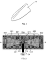
- Figure 1 shows a typical shark fin antenna unit 100 that may be placed at the rear of the rooftop of a vehicle. Antennas inside the antenna unit 100 are restricted in dimensions and the antennas have to be adapted to fit the unit 100.
- the antenna unit 100 also has stringent requirements for weather protection, shock behaviour and sensitivity to rises in temperature.
- the antenna unit 100 is encapsulated by a plastic randome.
- Typical dimensions of the antenna unit 100 are:
- FIG. 2 illustrates the prior art wireless link module of US7612720 (B2 ).
- the wireless link module comprises a lower band antenna and a higher band antenna.
- Each of these antennas comprises an antenna element with a feeding end and an open end.
- the respective antenna elements are substantially capacitively coupled.
- Figure 3 illustrates the input impedance of the prior art antenna of Figure 2 on a Smith chart.
- the Smith chart is a commonly used method of displaying complex information related to the impedance performance of an antenna.
- the circumferential axis shows the reactive coefficient of the antenna relative to a reference level of 50 ⁇ .
- the horizontal linear axis shows the resistive coefficient relative to this reference level.
- the function plotted on the graph shows the two components of the impedance of the antenna at different frequencies, with the frequency increasing as the function traces a clockwise motion.
- One or more embodiments disclosed herein relate to a multiband antenna that can be used in proximity with a large grounding body, such as the large effective ground plane that is present when an antenna is situated on the roof of a vehicle.
- Figures 4a , 4b and 4c illustrate a multiband antenna 400 according to an embodiment of the invention.
- Figure 4a shows a front view of the antenna 400, and illustrates a first, front, surface of the substrate 402.
- Figure 4b shows a back view of the antenna 400, and illustrates a second, reverse, surface of the substrate 402.
- Figure 4c shows a composite view of the front and back views of the antenna.
- the antenna 400 has a substrate 402, with a first conductive plate 404 on a first surface of the substrate 402 and a second conductive plate 408 on a second, opposite side of the substrate 402.
- the first conductive plate 404 provides a lower band antenna and the second conductive plate 408 provides a higher band antenna.
- the first and second conductive plates 404, 408 are quarter wavelength monopole antennas.
- the substrate 402 can be a printed circuit board (PCB) material such as FR4, or any dielectric material that has sufficient performance for the frequency bands of operation.
- PCB printed circuit board
- the substrate 402 can be low cost in terms of materials and also low cost for manufacturing as existing technologies for printed circuit boards can be used to provide the conductive plates 404, 408 on the substrate 402.
- the conductive plates 404, 408 can be copper or any other material that has sufficient performance for the frequency bands of operation.
- the conductive plates 404, 408 can be very thin, for example 35 micrometers.
- the conductive plates 404, 408 can be covered by a protective layer to prevent or reduce oxidation of the conductive plates 404, 408 and/or to reduce degradation due to temperature. Such requirements may be beneficial in order for the antenna 200 to satisfy automotive requirements.
- the substrate 402 may be, for example, a glass epoxy material, which is commonly used for printed circuit boards.
- the substrate 402 may be, for example, 1.2 millimeters (mm) thick, 15 mm wide and 25 mm long.
- the first conductive plate 404 and the second conductive plate 408 may be formed by etching copper, which is commonly used for printed circuit boards. Such an antenna construction can be considered convenient and low cost in terms of materials and construction.
- a connecting conductor 406 provides an electrical connection between the first and second conductive plates 404, 408.
- the connecting conductor 406 is a via that passes through the substrate 402, although in other embodiments different types of connecting conductor 406 can be used in order to provide a direct electrical connection between the two conductive plates 404, 408.
- Providing a direct electrical connection between the two conductive plates 404, 408 causes the electrical current that flows through the two conductive plates 404, 408 to be in-phase at the feeding end of the two conductive plates 404, 408 and therefore the current in one conductive plate 404, 408 does not interfere with the current in the other plate 404, 408. This is described and illustrated below with reference to Figures 7 and 8 where it can be seen that the directionality of the antenna is not negatively affected by the combination of two conductive plates 404, 408.
- a feeding port 412 is coupled to the connecting conductor 406 and is configured to conduct signals that are received at, or transmitted from, the antenna 400.
- the feeding port 412 may be connected to an inner conductor of a coaxial cable.
- An advantage provided by the single feeding port 412 and connecting conductor 406 is that only a single feed is required, which can reduce the cost of the antenna and coaxial cable that is required.
- the outer shielding conductor of such a coaxial cable may be connected to a ground plane 410, which is described in more detail below.
- the antenna assembly 400 also has a ground plane 410.
- the substrate 402 is attached to the ground plane 410 such that it is perpendicular to the ground plane 410. In use, the substrate can be positioned vertically with reference to the rooftop of a vehicle.
- the front surface of the substrate 402 supports the first conductive plate 404, which is perpendicular to the ground plane 410.
- the back surface of the substrate 402 supports the second conductive plate 408, which is also perpendicular to the ground plane 410.
- Each conductive plate 404, 408 may be considered as an antenna element in the form of a conductive path that extends from a feeding end 416, 420 to an open end 414, 418.
- the feeding ends 416, 420 are coupled to the connecting conductor 406, which in turn is connected to the feeding port 412 in order to conduct signals to and from the antenna 400.
- the length of the conductive path of each conductive plate 404, 408 is approximately a quarter of a wavelength of the signals that are to be received at, or transmitted from, that conductive plate 404, 408. That is, the distance between the feeding end 416, 420 and the open end 414, 418 of an antenna element is substantially a quarter of a wavelength.
- the conductive plates 404, 480 can be considered as extending in a longitudinal direction from their feeding ends 416, 420 to their open ends 414,418.
- the first conductive plate 404 in this example is rectangular in shape, and is significantly longer in a longitudinal direction than in a lateral direction.
- the rectangular first conductive plate 404 can be long and thin, for example the conductive plate 404 may be about 10 to 500 times longer (longitudinal length) than it is wide (lateral length).
- the lateral width of the second conductive plate 408 is smaller at the feeding end 420 than at the open end 418. This can provide good input impedance coupling for the second conductive plate 408.
- the second conductive plate 408 has a substantially square or rectangular section at the open end 418, and a triangular or frusto-triangular section at the feeding end 406.
- the lateral width of the second conductive plate 408 may be similar to the longitudinal length of the second conductive plate 408. For example, the lateral width may be within about 2%, 5%, 8% or 50% of the longitudinal length.
- the connecting conductor 406 which may also be referred to as an antenna coupling short, is relatively close to the respective feeding ends 416, 420 of the conductive plates 404, 408.
- the distance between the connecting conductor 406 and the feeding end 420 may be at least 10 times less than the distance between the connecting conductor 406 and the open end 418.
- the antenna assembly 400 can be fed at only at one of the feeding ends 416, 420, the other feeding end 416, 420 can be left open.
- the first and second conductive plates 404, 418 at least partially overlap, consequently there is capacitive coupling between first and second conductive plates 404, 418. It has been found that the capacitive coupling between the first and second conductive plates 404, 418 should not be too large as the multiband antenna will not function satisfactorily in the presence of the ground plane 410. In some examples, it can be advantageous for less than about 5%, 15% or 25% of the first conductive plate 404 to overlap with the second conductive plate 408, and/or for less than about 35%, 45% or 55% of the second conductive plate 408 to overlap with the first conductive plate 404.
- the capacitive coupling between the conductive plates 404, 408 is distributed, as it were, over a significant portion of the respective conductive paths, which form these antenna elements.
- the connecting conductor 406 is absent.
- the first and second conductive plates 404, 408 could be considered as a capacitor.
- such a capacitor would have a relatively low impedance at the frequencies of interest (of the order of 2 GHz to in excess of 5 GHz), and therefore would not provide satisfactory performance at those frequencies.
- the input impedance of the antenna 400 of Figure 4 is sufficiently high due to the presence of the connecting conductor 406.
- the multiband antenna 400 of Figure 4 may be provided in a shark fin antenna module that is suitable for fixing to the rooftop of an automobile such as a car.
- the ground plane 410 may be a bottom plate of the shark fin module, and in some examples can be considered as an extension of the roof of the car.
- Such an antenna module may be used, for example, to establish communication in accordance with the IEEE802.11a/b/g/p standard.
- the first conductive plate 404 of the lower band antenna constitutes a quarter wavelength monopole at this frequency.
- the antenna assembly 400 behaves almost as if only the lower band antenna of Figure 4a were present; the higher band antenna of Figure 4b has no significant influence.
- Two features of the antenna structure can account for this behavior.
- the connecting conductor 406 can provide this functionality as it electrically couples the first conductive plate 404 to the second conductive plate 408 and their respective feeding ends 416, 420.
- the separated second conductive plate 408 presents a small capacitance with the first conductive plate 404 at the lower frequency band since the length of the second conductive plate 408 is only 0.25 wavelength at the lower frequency band.
- the impedance due to the small capacitive coupling between the antenna element of Figure 4a and the antenna element of Figure 4b can allow a good impedance matching, and as a result can provide efficient operation while the antenna is operated at or near the resonant frequency.
- the second conductive plate 408 of the higher band antenna constitutes a quarter wavelength monopole at this frequency.
- the first conductive plate 404 of the lower band antenna constitutes almost a half wavelength at this frequency, represents a relatively high impedance when taken in isolation. Consequently, the higher band antenna of Figure 4b has the predominant effect on the input impedance of the antenna assembly 400 at 5.5 GHz, as the impedances of the higher and lower bands are in parallel with each other.
- the input impedance can allow a good impedance matching, and as a result can provide efficient operation while the antenna is operated at or near the resonant frequencies.
- the lower band antenna of Figure 4a can play a significant role from a radiation point of view at 5.5 GHz (the higher frequency). This can be due to the weak capacitive coupling between the conductive plates 404, 408, which can cause a current to flow through the first conductive plate 404 of the lower band antenna when the higher frequency signal of 5.5 GHz is applied to the antenna assembly 400. As a result, the lower band antenna may radiate an electromagnetic field, which has an impact on the radiation characteristics of the antenna assembly at 5.5 GHz.
- the connecting conductor 406 can cause the lower band antenna and the higher band antenna to have an equal phase at their feeding ends 416, 420, and therefore not to negatively influence each other. This is described in more detail in relation to Figures 7 and 8 .
- Figure 5 illustrates the simulated return loss of an antenna with the structure of Figure 4 that has been designed for operation at frequencies of about 2.45GHz and 5.5GHz.
- Figure 6 illustrates the simulated input impedance of the same antenna in the form of a Smith chart.
- a lower frequency band of operation 502 and a higher frequency band of operation 504 are shown in Figure 5 .
- the bandwidth of the frequency bands 502, 504 are shown at a reference level of return loss of -10 dB.
- the return loss is the loss of signal at the antenna due to poorly matched impedance of the antenna and the line that feeds it; it is the loss due to reflected signal.
- the return loss is a parameter commonly used to define the quality of matching of the radio frequency signal to the antenna.
- the centre frequencies of the two frequency bands are identified with references 602, 604 in Figure 6 .
- the impedance 602 at 2.45 GHz is (41 + 20j) ⁇
- the impedance 604 at 5.5 GHz is (69 + 0j) ⁇ .
- the antenna coupling at these frequencies can be said not to have capacitive character; the capacitive coupling between the first conductive plate 404 and the second conductive plate 408 is very weak at the middle of the frequency bands of interest.
- Figure 7 illustrates graphically the simulated radiation pattern of the same antenna at 2.45 GHz and Figure 8 illustrates the simulated radiation pattern at 5.5 GHz.
- Both radiating patterns are substantially omnidirectional, in a plane that is substantially perpendicular to the substrate 402. In this example, such a plane is substantially parallel to the ground plane 410.
- the omnidirectional radiating pattern in both frequency bands can be achieved due to the connecting conductor 406 and the small capacitive coupling between the conductive plates 404, 408. As discussed above, this structure can ensure that current flowing through the two conductive plates 404, 408 is in-phase and therefore reinforces the radiation pattern.
- the antenna assembly 400 provides improved antenna gain in the plane parallel to the ground plane. This is illustrated in Figure 8 where it can be seen that a greater proportion of the radiated energy is focused in a horizontal direction, as opposed to a vertical direction.
- the antenna gain in the higher frequency band may be advantageous in some examples as it can compensate for signal losses in the coaxial cable at these high frequencies. Such signal losses in the coaxial cable can be generally higher in the higher frequency band than in the lower frequency band.
- Figures 9a to 9c illustrate an antenna 900 according to an alternative embodiment of the invention.
- Figure 9a shows a front view of the antenna 900
- Figure 9b shows a back view of the antenna 900
- Figure 9c shows a composite view of the front and back views of the antenna 900.
- the second conductive plate 908 of this embodiment is substantially square, and does not have the frusto-triangular section of the antenna of Figures 4a to 4c .
- the frusto-triangular section of the second conductive plate of Figures 4a to 4c can increase the bandwidth at which the antenna can satisfactorily operate.
- the feeding port 912 is coupled to the second conductive plate 908 at two laterally spaced apart locations 936, 938.
- the feeding port 912 is coupled to a connecting conductor 906, such as a via through the substrate 902.
- a connecting conductor 906 such as a via through the substrate 902.
- the connecting conductor 906 is electrically connected to the second conductive plate 908 by two conductive paths 930, 932, 934 that meet the second conductive plate 908 at two separate locations 936, 938.
- current distribution through the second conductive plate 908 is spread in a lateral direction thereby increasing the fractional bandwidth of signals in the higher frequency band that can be received at, or transmitted from, the second conductive plate 908.
- antennas of Figures 4a to 4c and 9a to 9c are only examples of an embodiment of the invention, that the dimensions illustrated are not to be considered as limiting, and that the antenna can be designed to be suitable for other frequency bands.
- One or more embodiments disclosed herein relate to a dual band antenna assembly operating against a ground plane that comprises a lower band antenna and a higher band antenna.
- Each of these antennas comprises an antenna element (also referred to herein as a conductive plate) with a feeding end and an open end.
- the respective antenna elements are weak capacitive coupled.
- the respective antenna elements are electrically coupled at the respective feeding ends via an antenna coupling short (also referred to as connecting conductor herein).
Landscapes
- Engineering & Computer Science (AREA)
- Remote Sensing (AREA)
- Details Of Aerials (AREA)
- Waveguide Aerials (AREA)
- Variable-Direction Aerials And Aerial Arrays (AREA)
Claims (10)
- Eine Multiband-Antenne (400) aufweisend:ein Substrat (402), welches eine erste Oberfläche und eine zweite Oberfläche hat;eine erste leitfähige Platte (404) auf der ersten Oberfläche von dem Substrat (402);eine zweite leitfähige Platte (408) auf der zweiten Oberfläche von dem Substrat (402), wobei die zweite leitfähige Platte (408) die erste leitfähige Platte (404) in der Ebene von dem Substrat zumindest teilweise überlappt,eine Grund-Ebene (410), wobei das Substrat (402) an die Grund-Ebene (410) verbunden ist und im Wesentlichen senkrecht zu der Grund-Ebene (410) ist;einen zuführenden Anschluss (412), welcher elektrisch sowohl an die erste leitfähige Platte (404) als auch an die zweite leitfähige Platte (408) gekoppelt ist; wobeidie erste leitfähige Platte (404) und die zweite leitfähige Platte (408) sich von der Grund-Ebene (410) weg in einer longitudinalen Richtung erstrecken,
und wobei die Länge von der ersten leitfähigen Platte (404) in der longitudinalen Richtung zu einer Viertel Wellenlänge von der Signal-Frequenz korrespondiert, welche die erste leitfähige Platte (404) konfiguriert ist zu übertragen und zu empfangen,
und die Länge von der zweiten leitfähigen Platte (408) in der longitudinalen Richtung zu einer Viertel Wellenlänge von der Signal-Frequenz korrespondiert, welche die zweite leitfähige Platte (408) konfiguriert ist zu übertragen und zu empfangen,
wobei die Multiband-Antenne dadurch gekennzeichnet ist, dass weniger als etwa 15 % von der zweiten leitfähigen Platte (408) die erste leitfähige Platte (404) überlappt,
weniger als etwa 45 % von der ersten leitfähigen Platte (404) die zweite leitfähige Platte (408) überlappt,
und dadurch, dass
die Multiband-Antenne ferner einen verbindenden Leiter (406) aufweist, welcher konfiguriert ist zum Bereitstellen einer elektrischen Verbindung zwischen der ersten leitfähigen Platte (404), der zweiten leitfähigen Platte (408) und dem zuführenden Anschluss (412). - Die Antenne gemäß Anspruch 1, wobei die Länge von der ersten leitfähigen Platte (404) und der zweiten leitfähigen Platte (408) in der longitudinalen Richtung die Signal-Frequenzen definiert, welche die Platten (404, 408) konfiguriert sind zu übertragen und zu empfangen.
- Die Antenne gemäß Anspruch 1 oder 2, wobei sich die Proportion von der ersten leitfähigen Platte (404), welche die zweite leitfähige Platte (408) überlappt, von der Proportion von der zweiten leitfähigen Platte (408), welche die erste leitfähige Platte (404) überlappt, um zumindest 10 % unterscheidet.
- Die Antenne gemäß einem beliebigen vorhergehenden Anspruch, wobei die erste leitfähige Platte (404) rechteckig ist.
- Die Antenne gemäß einem beliebigen vorhergehenden Anspruch, wobei die zweite leitfähige Platte (408) einen im Wesentlichen quadratischen oder rechteckigen Abschnitt an einem offenen Ende (418) hat, und
einen Dreieck-Stumpf-förmigen Abschnitt an einem zuliefernden Ende (406) hat. - Die Antenne gemäß einem beliebigen vorhergehenden Anspruch, wobei die erste leitfähige Platte (404) konfiguriert ist zum Übertragen und Empfangen von Signalen mit einer Frequenz von etwa 2,5 GHz.
- Die Antenne gemäß einem beliebigen vorhergehenden Anspruch, wobei die zweite leitfähige Platte (408) konfiguriert es zum Übertragen und Empfangen von Signalen einer Frequenz, welche größer als etwa 5 GHz ist.
- Die Antenne gemäß einem beliebigen vorhergehenden Anspruch, wobei der zuliefernde Anschluss (912) an die zweite leitfähige Platte (908) gekoppelt ist an zwei seitlich voneinander abgetrennten Bereichen (936, 938).
- Die Antenne gemäß einem beliebigen vorhergehenden Anspruch, aufweisend einen einzelnen zuliefernden Anschluss (412) für sowohl die erste leitfähige Platte (404) als auch für die zweite leitfähige Platte (408), und
wobei der zuliefernde Anschluss konfiguriert ist, um an einen inneren Leiter von einem Koaxialkabel verbunden zu sein. - Die Antenne (400) gemäß einem beliebigen vorhergehenden Anspruch, wobei die Grund-Ebene (410) konfiguriert ist, um an ein leitfähiges Schirm von einem Koaxialkabel verbunden zu sein.
Priority Applications (3)
| Application Number | Priority Date | Filing Date | Title |
|---|---|---|---|
| EP11250242.2A EP2495807B1 (de) | 2011-03-03 | 2011-03-03 | Mehrbandantenne |
| US13/406,550 US9379430B2 (en) | 2011-03-03 | 2012-02-28 | Multiband antenna |
| CN201210048070.5A CN102655266B (zh) | 2011-03-03 | 2012-02-28 | 多频带天线 |
Applications Claiming Priority (1)
| Application Number | Priority Date | Filing Date | Title |
|---|---|---|---|
| EP11250242.2A EP2495807B1 (de) | 2011-03-03 | 2011-03-03 | Mehrbandantenne |
Publications (2)
| Publication Number | Publication Date |
|---|---|
| EP2495807A1 EP2495807A1 (de) | 2012-09-05 |
| EP2495807B1 true EP2495807B1 (de) | 2016-09-14 |
Family
ID=44314914
Family Applications (1)
| Application Number | Title | Priority Date | Filing Date |
|---|---|---|---|
| EP11250242.2A Active EP2495807B1 (de) | 2011-03-03 | 2011-03-03 | Mehrbandantenne |
Country Status (3)
| Country | Link |
|---|---|
| US (1) | US9379430B2 (de) |
| EP (1) | EP2495807B1 (de) |
| CN (1) | CN102655266B (de) |
Families Citing this family (6)
| Publication number | Priority date | Publication date | Assignee | Title |
|---|---|---|---|---|
| GB201213558D0 (en) | 2012-07-31 | 2012-09-12 | Univ Birmingham | Reconfigurable antenna |
| GB2507788A (en) | 2012-11-09 | 2014-05-14 | Univ Birmingham | Vehicle roof mounted reconfigurable MIMO antenna |
| KR101470157B1 (ko) * | 2013-05-20 | 2014-12-05 | 현대자동차주식회사 | 차량용 안테나 |
| US9786990B2 (en) * | 2014-02-24 | 2017-10-10 | R.A. Miller Industries, Inc. | Integrated multiband antenna |
| GB2532978B (en) * | 2014-12-04 | 2016-12-14 | Frontier Silicon Ltd | Antenna module |
| US20240186690A1 (en) * | 2022-12-01 | 2024-06-06 | Northrop Grumman Systems Corporation | Blade antenna system |
Citations (1)
| Publication number | Priority date | Publication date | Assignee | Title |
|---|---|---|---|---|
| JP2003133838A (ja) * | 2001-10-24 | 2003-05-09 | Alps Electric Co Ltd | モノポールアンテナ |
Family Cites Families (15)
| Publication number | Priority date | Publication date | Assignee | Title |
|---|---|---|---|---|
| US4395713A (en) * | 1980-05-06 | 1983-07-26 | Antenna, Incorporated | Transit antenna |
| GB9517241D0 (en) | 1995-08-23 | 1995-10-25 | Philips Electronics Uk Ltd | Printed antenna |
| US5828340A (en) * | 1996-10-25 | 1998-10-27 | Johnson; J. Michael | Wideband sub-wavelength antenna |
| WO2001013464A1 (en) * | 1999-08-18 | 2001-02-22 | Ericsson, Inc. | A dual band bowtie/meander antenna |
| US6809687B2 (en) * | 2001-10-24 | 2004-10-26 | Alps Electric Co., Ltd. | Monopole antenna that can easily be reduced in height dimension |
| US6791506B2 (en) | 2002-10-23 | 2004-09-14 | Centurion Wireless Technologies, Inc. | Dual band single feed dipole antenna and method of making the same |
| US6819290B2 (en) * | 2003-04-08 | 2004-11-16 | Motorola Inc. | Variable multi-band planar antenna assembly |
| JP2005229161A (ja) * | 2004-02-10 | 2005-08-25 | Taiyo Yuden Co Ltd | アンテナ及び当該アンテナを有する無線通信機器 |
| US7274334B2 (en) | 2005-03-24 | 2007-09-25 | Tdk Corporation | Stacked multi-resonator antenna |
| CN101167214A (zh) | 2005-04-25 | 2008-04-23 | 皇家飞利浦电子股份有限公司 | 包括两个天线的无线链路模块 |
| DE102005054286B4 (de) | 2005-11-11 | 2011-04-07 | Delphi Delco Electronics Europe Gmbh | Antennenanordnung |
| US7969361B2 (en) | 2006-03-14 | 2011-06-28 | Broadcom Corporation | Planar inverted-F antenna |
| CN101162801B (zh) | 2006-10-13 | 2011-07-27 | 鸿富锦精密工业(深圳)有限公司 | 双频天线及使用该双频天线的多输入输出天线 |
| KR100899293B1 (ko) * | 2007-04-04 | 2009-05-27 | 주식회사 이엠따블유안테나 | 이중공진에 의한 광대역 안테나 |
| EP2256859A1 (de) | 2009-05-12 | 2010-12-01 | ST-Ericsson SA | Antennenanordnung, Verfahren zum Anpassen einer Antennenanordnung und Vorrichtung mit Antennenanordnung |
-
2011
- 2011-03-03 EP EP11250242.2A patent/EP2495807B1/de active Active
-
2012
- 2012-02-28 CN CN201210048070.5A patent/CN102655266B/zh active Active
- 2012-02-28 US US13/406,550 patent/US9379430B2/en active Active
Patent Citations (1)
| Publication number | Priority date | Publication date | Assignee | Title |
|---|---|---|---|---|
| JP2003133838A (ja) * | 2001-10-24 | 2003-05-09 | Alps Electric Co Ltd | モノポールアンテナ |
Also Published As
| Publication number | Publication date |
|---|---|
| US9379430B2 (en) | 2016-06-28 |
| CN102655266A (zh) | 2012-09-05 |
| US20120223863A1 (en) | 2012-09-06 |
| EP2495807A1 (de) | 2012-09-05 |
| CN102655266B (zh) | 2014-09-10 |
Similar Documents
| Publication | Publication Date | Title |
|---|---|---|
| EP2495809B1 (de) | Mehrbandantenne | |
| KR101102650B1 (ko) | 아이솔레이션 향상을 위한 mimo 안테나 | |
| KR101547746B1 (ko) | 섀시 여기 안테나 컴포넌트, 안테나 장치 및 이에 대한 모바일 통신 디바이스 | |
| US6218992B1 (en) | Compact, broadband inverted-F antennas with conductive elements and wireless communicators incorporating same | |
| KR100771775B1 (ko) | 수직배열 내장형 안테나 | |
| US8928537B2 (en) | Multiband antenna | |
| EP2495807B1 (de) | Mehrbandantenne | |
| JP2009531978A (ja) | 無線通信のための変形逆−f字アンテナ | |
| CN101595598A (zh) | 内部多频带天线 | |
| US20170170555A1 (en) | Decoupled Antennas For Wireless Communication | |
| US9837699B2 (en) | Multi-element window antenna | |
| JP4169696B2 (ja) | 高バンド幅マルチバンド・アンテナ | |
| JP3469834B2 (ja) | 広帯域アレーアンテナ | |
| EP3154125B1 (de) | Mehrbandantenne mit acht frequenzen | |
| EP3154124B1 (de) | Zehn-frequenz-bandantenne | |
| US11699856B1 (en) | Vehicular half loop antenna and vehicular antenna device | |
| CN113078445A (zh) | 天线结构及具有该天线结构的无线通信装置 | |
| KR100922230B1 (ko) | 다층 안테나 | |
| CN108428999B (zh) | 天线 | |
| CN115917878A (zh) | 车辆用通信装置 | |
| CN107534211A (zh) | 小型天线结构 | |
| KR101718922B1 (ko) | 차량용 다중대역안테나 | |
| WO2011049351A2 (ko) | Lc 필터를 이용한 다중 대역 안테나 | |
| US11973277B2 (en) | Antenna module and antenna device having the same | |
| WO2023090212A1 (ja) | 半波長アンテナ装置及びそれを用いる低背型アンテナ装置 |
Legal Events
| Date | Code | Title | Description |
|---|---|---|---|
| PUAI | Public reference made under article 153(3) epc to a published international application that has entered the european phase |
Free format text: ORIGINAL CODE: 0009012 |
|
| AK | Designated contracting states |
Kind code of ref document: A1 Designated state(s): AL AT BE BG CH CY CZ DE DK EE ES FI FR GB GR HR HU IE IS IT LI LT LU LV MC MK MT NL NO PL PT RO RS SE SI SK SM TR |
|
| AX | Request for extension of the european patent |
Extension state: BA ME |
|
| 17P | Request for examination filed |
Effective date: 20130305 |
|
| 17Q | First examination report despatched |
Effective date: 20140508 |
|
| RIC1 | Information provided on ipc code assigned before grant |
Ipc: H01Q 5/371 20150101ALI20160309BHEP Ipc: H01Q 21/30 20060101ALI20160309BHEP Ipc: H01Q 1/38 20060101ALI20160309BHEP Ipc: H01Q 5/00 20150101ALI20160309BHEP Ipc: H01Q 1/32 20060101AFI20160309BHEP Ipc: H01Q 9/38 20060101ALI20160309BHEP |
|
| GRAP | Despatch of communication of intention to grant a patent |
Free format text: ORIGINAL CODE: EPIDOSNIGR1 |
|
| INTG | Intention to grant announced |
Effective date: 20160422 |
|
| RIN1 | Information on inventor provided before grant (corrected) |
Inventor name: KERSELAERS, ANTHONY |
|
| GRAS | Grant fee paid |
Free format text: ORIGINAL CODE: EPIDOSNIGR3 |
|
| GRAA | (expected) grant |
Free format text: ORIGINAL CODE: 0009210 |
|
| AK | Designated contracting states |
Kind code of ref document: B1 Designated state(s): AL AT BE BG CH CY CZ DE DK EE ES FI FR GB GR HR HU IE IS IT LI LT LU LV MC MK MT NL NO PL PT RO RS SE SI SK SM TR |
|
| REG | Reference to a national code |
Ref country code: GB Ref legal event code: FG4D |
|
| REG | Reference to a national code |
Ref country code: CH Ref legal event code: EP |
|
| REG | Reference to a national code |
Ref country code: IE Ref legal event code: FG4D |
|
| REG | Reference to a national code |
Ref country code: AT Ref legal event code: REF Ref document number: 829893 Country of ref document: AT Kind code of ref document: T Effective date: 20161015 |
|
| REG | Reference to a national code |
Ref country code: DE Ref legal event code: R096 Ref document number: 602011030310 Country of ref document: DE |
|
| REG | Reference to a national code |
Ref country code: LT Ref legal event code: MG4D |
|
| REG | Reference to a national code |
Ref country code: NL Ref legal event code: MP Effective date: 20160914 |
|
| PG25 | Lapsed in a contracting state [announced via postgrant information from national office to epo] |
Ref country code: RS Free format text: LAPSE BECAUSE OF FAILURE TO SUBMIT A TRANSLATION OF THE DESCRIPTION OR TO PAY THE FEE WITHIN THE PRESCRIBED TIME-LIMIT Effective date: 20160914 Ref country code: HR Free format text: LAPSE BECAUSE OF FAILURE TO SUBMIT A TRANSLATION OF THE DESCRIPTION OR TO PAY THE FEE WITHIN THE PRESCRIBED TIME-LIMIT Effective date: 20160914 Ref country code: LT Free format text: LAPSE BECAUSE OF FAILURE TO SUBMIT A TRANSLATION OF THE DESCRIPTION OR TO PAY THE FEE WITHIN THE PRESCRIBED TIME-LIMIT Effective date: 20160914 Ref country code: NO Free format text: LAPSE BECAUSE OF FAILURE TO SUBMIT A TRANSLATION OF THE DESCRIPTION OR TO PAY THE FEE WITHIN THE PRESCRIBED TIME-LIMIT Effective date: 20161214 Ref country code: FI Free format text: LAPSE BECAUSE OF FAILURE TO SUBMIT A TRANSLATION OF THE DESCRIPTION OR TO PAY THE FEE WITHIN THE PRESCRIBED TIME-LIMIT Effective date: 20160914 |
|
| REG | Reference to a national code |
Ref country code: AT Ref legal event code: MK05 Ref document number: 829893 Country of ref document: AT Kind code of ref document: T Effective date: 20160914 |
|
| REG | Reference to a national code |
Ref country code: FR Ref legal event code: PLFP Year of fee payment: 7 |
|
| PG25 | Lapsed in a contracting state [announced via postgrant information from national office to epo] |
Ref country code: GR Free format text: LAPSE BECAUSE OF FAILURE TO SUBMIT A TRANSLATION OF THE DESCRIPTION OR TO PAY THE FEE WITHIN THE PRESCRIBED TIME-LIMIT Effective date: 20161215 Ref country code: SE Free format text: LAPSE BECAUSE OF FAILURE TO SUBMIT A TRANSLATION OF THE DESCRIPTION OR TO PAY THE FEE WITHIN THE PRESCRIBED TIME-LIMIT Effective date: 20160914 Ref country code: NL Free format text: LAPSE BECAUSE OF FAILURE TO SUBMIT A TRANSLATION OF THE DESCRIPTION OR TO PAY THE FEE WITHIN THE PRESCRIBED TIME-LIMIT Effective date: 20160914 Ref country code: LV Free format text: LAPSE BECAUSE OF FAILURE TO SUBMIT A TRANSLATION OF THE DESCRIPTION OR TO PAY THE FEE WITHIN THE PRESCRIBED TIME-LIMIT Effective date: 20160914 |
|
| PG25 | Lapsed in a contracting state [announced via postgrant information from national office to epo] |
Ref country code: RO Free format text: LAPSE BECAUSE OF FAILURE TO SUBMIT A TRANSLATION OF THE DESCRIPTION OR TO PAY THE FEE WITHIN THE PRESCRIBED TIME-LIMIT Effective date: 20160914 Ref country code: EE Free format text: LAPSE BECAUSE OF FAILURE TO SUBMIT A TRANSLATION OF THE DESCRIPTION OR TO PAY THE FEE WITHIN THE PRESCRIBED TIME-LIMIT Effective date: 20160914 |
|
| PG25 | Lapsed in a contracting state [announced via postgrant information from national office to epo] |
Ref country code: CZ Free format text: LAPSE BECAUSE OF FAILURE TO SUBMIT A TRANSLATION OF THE DESCRIPTION OR TO PAY THE FEE WITHIN THE PRESCRIBED TIME-LIMIT Effective date: 20160914 Ref country code: BG Free format text: LAPSE BECAUSE OF FAILURE TO SUBMIT A TRANSLATION OF THE DESCRIPTION OR TO PAY THE FEE WITHIN THE PRESCRIBED TIME-LIMIT Effective date: 20161214 Ref country code: SM Free format text: LAPSE BECAUSE OF FAILURE TO SUBMIT A TRANSLATION OF THE DESCRIPTION OR TO PAY THE FEE WITHIN THE PRESCRIBED TIME-LIMIT Effective date: 20160914 Ref country code: PT Free format text: LAPSE BECAUSE OF FAILURE TO SUBMIT A TRANSLATION OF THE DESCRIPTION OR TO PAY THE FEE WITHIN THE PRESCRIBED TIME-LIMIT Effective date: 20170116 Ref country code: IS Free format text: LAPSE BECAUSE OF FAILURE TO SUBMIT A TRANSLATION OF THE DESCRIPTION OR TO PAY THE FEE WITHIN THE PRESCRIBED TIME-LIMIT Effective date: 20170114 Ref country code: AT Free format text: LAPSE BECAUSE OF FAILURE TO SUBMIT A TRANSLATION OF THE DESCRIPTION OR TO PAY THE FEE WITHIN THE PRESCRIBED TIME-LIMIT Effective date: 20160914 Ref country code: SK Free format text: LAPSE BECAUSE OF FAILURE TO SUBMIT A TRANSLATION OF THE DESCRIPTION OR TO PAY THE FEE WITHIN THE PRESCRIBED TIME-LIMIT Effective date: 20160914 Ref country code: ES Free format text: LAPSE BECAUSE OF FAILURE TO SUBMIT A TRANSLATION OF THE DESCRIPTION OR TO PAY THE FEE WITHIN THE PRESCRIBED TIME-LIMIT Effective date: 20160914 Ref country code: PL Free format text: LAPSE BECAUSE OF FAILURE TO SUBMIT A TRANSLATION OF THE DESCRIPTION OR TO PAY THE FEE WITHIN THE PRESCRIBED TIME-LIMIT Effective date: 20160914 Ref country code: BE Free format text: LAPSE BECAUSE OF FAILURE TO SUBMIT A TRANSLATION OF THE DESCRIPTION OR TO PAY THE FEE WITHIN THE PRESCRIBED TIME-LIMIT Effective date: 20160914 |
|
| REG | Reference to a national code |
Ref country code: DE Ref legal event code: R097 Ref document number: 602011030310 Country of ref document: DE |
|
| PG25 | Lapsed in a contracting state [announced via postgrant information from national office to epo] |
Ref country code: IT Free format text: LAPSE BECAUSE OF FAILURE TO SUBMIT A TRANSLATION OF THE DESCRIPTION OR TO PAY THE FEE WITHIN THE PRESCRIBED TIME-LIMIT Effective date: 20160914 |
|
| PLBE | No opposition filed within time limit |
Free format text: ORIGINAL CODE: 0009261 |
|
| STAA | Information on the status of an ep patent application or granted ep patent |
Free format text: STATUS: NO OPPOSITION FILED WITHIN TIME LIMIT |
|
| PG25 | Lapsed in a contracting state [announced via postgrant information from national office to epo] |
Ref country code: DK Free format text: LAPSE BECAUSE OF FAILURE TO SUBMIT A TRANSLATION OF THE DESCRIPTION OR TO PAY THE FEE WITHIN THE PRESCRIBED TIME-LIMIT Effective date: 20160914 |
|
| 26N | No opposition filed |
Effective date: 20170615 |
|
| REG | Reference to a national code |
Ref country code: CH Ref legal event code: PL |
|
| GBPC | Gb: european patent ceased through non-payment of renewal fee |
Effective date: 20170303 |
|
| PG25 | Lapsed in a contracting state [announced via postgrant information from national office to epo] |
Ref country code: SI Free format text: LAPSE BECAUSE OF FAILURE TO SUBMIT A TRANSLATION OF THE DESCRIPTION OR TO PAY THE FEE WITHIN THE PRESCRIBED TIME-LIMIT Effective date: 20160914 Ref country code: MC Free format text: LAPSE BECAUSE OF FAILURE TO SUBMIT A TRANSLATION OF THE DESCRIPTION OR TO PAY THE FEE WITHIN THE PRESCRIBED TIME-LIMIT Effective date: 20160914 |
|
| REG | Reference to a national code |
Ref country code: IE Ref legal event code: MM4A |
|
| PG25 | Lapsed in a contracting state [announced via postgrant information from national office to epo] |
Ref country code: LU Free format text: LAPSE BECAUSE OF NON-PAYMENT OF DUE FEES Effective date: 20170303 |
|
| REG | Reference to a national code |
Ref country code: FR Ref legal event code: PLFP Year of fee payment: 8 |
|
| PG25 | Lapsed in a contracting state [announced via postgrant information from national office to epo] |
Ref country code: CH Free format text: LAPSE BECAUSE OF NON-PAYMENT OF DUE FEES Effective date: 20170331 Ref country code: IE Free format text: LAPSE BECAUSE OF NON-PAYMENT OF DUE FEES Effective date: 20170303 Ref country code: GB Free format text: LAPSE BECAUSE OF NON-PAYMENT OF DUE FEES Effective date: 20170303 Ref country code: LI Free format text: LAPSE BECAUSE OF NON-PAYMENT OF DUE FEES Effective date: 20170331 |
|
| PG25 | Lapsed in a contracting state [announced via postgrant information from national office to epo] |
Ref country code: MT Free format text: LAPSE BECAUSE OF NON-PAYMENT OF DUE FEES Effective date: 20170303 |
|
| PG25 | Lapsed in a contracting state [announced via postgrant information from national office to epo] |
Ref country code: AL Free format text: LAPSE BECAUSE OF FAILURE TO SUBMIT A TRANSLATION OF THE DESCRIPTION OR TO PAY THE FEE WITHIN THE PRESCRIBED TIME-LIMIT Effective date: 20160914 |
|
| PG25 | Lapsed in a contracting state [announced via postgrant information from national office to epo] |
Ref country code: HU Free format text: LAPSE BECAUSE OF FAILURE TO SUBMIT A TRANSLATION OF THE DESCRIPTION OR TO PAY THE FEE WITHIN THE PRESCRIBED TIME-LIMIT; INVALID AB INITIO Effective date: 20110303 |
|
| PG25 | Lapsed in a contracting state [announced via postgrant information from national office to epo] |
Ref country code: CY Free format text: LAPSE BECAUSE OF NON-PAYMENT OF DUE FEES Effective date: 20160914 |
|
| PG25 | Lapsed in a contracting state [announced via postgrant information from national office to epo] |
Ref country code: MK Free format text: LAPSE BECAUSE OF FAILURE TO SUBMIT A TRANSLATION OF THE DESCRIPTION OR TO PAY THE FEE WITHIN THE PRESCRIBED TIME-LIMIT Effective date: 20160914 |
|
| PG25 | Lapsed in a contracting state [announced via postgrant information from national office to epo] |
Ref country code: TR Free format text: LAPSE BECAUSE OF FAILURE TO SUBMIT A TRANSLATION OF THE DESCRIPTION OR TO PAY THE FEE WITHIN THE PRESCRIBED TIME-LIMIT Effective date: 20160914 |
|
| P01 | Opt-out of the competence of the unified patent court (upc) registered |
Effective date: 20230725 |
|
| PGFP | Annual fee paid to national office [announced via postgrant information from national office to epo] |
Ref country code: DE Payment date: 20240220 Year of fee payment: 14 |
|
| PGFP | Annual fee paid to national office [announced via postgrant information from national office to epo] |
Ref country code: FR Payment date: 20240221 Year of fee payment: 14 |