EP2495542A1 - Fuel property detection device for construction equipment and construction equipment provided therewith - Google Patents
Fuel property detection device for construction equipment and construction equipment provided therewith Download PDFInfo
- Publication number
- EP2495542A1 EP2495542A1 EP10826276A EP10826276A EP2495542A1 EP 2495542 A1 EP2495542 A1 EP 2495542A1 EP 10826276 A EP10826276 A EP 10826276A EP 10826276 A EP10826276 A EP 10826276A EP 2495542 A1 EP2495542 A1 EP 2495542A1
- Authority
- EP
- European Patent Office
- Prior art keywords
- fuel
- tank
- sub
- detection device
- outlet
- Prior art date
- Legal status (The legal status is an assumption and is not a legal conclusion. Google has not performed a legal analysis and makes no representation as to the accuracy of the status listed.)
- Withdrawn
Links
- 239000000446 fuel Substances 0.000 title claims abstract description 342
- 238000001514 detection method Methods 0.000 title claims abstract description 154
- 238000010276 construction Methods 0.000 title claims description 31
- 239000002828 fuel tank Substances 0.000 claims abstract description 37
- 238000011056 performance test Methods 0.000 description 7
- 238000010586 diagram Methods 0.000 description 6
- 230000000694 effects Effects 0.000 description 6
- 238000007796 conventional method Methods 0.000 description 5
- 108010066114 cabin-2 Proteins 0.000 description 4
- 230000002708 enhancing effect Effects 0.000 description 3
- 230000000704 physical effect Effects 0.000 description 3
- 239000000126 substance Substances 0.000 description 3
- 238000001816 cooling Methods 0.000 description 2
- 239000007788 liquid Substances 0.000 description 2
- 238000012986 modification Methods 0.000 description 2
- 230000004048 modification Effects 0.000 description 2
- 230000015572 biosynthetic process Effects 0.000 description 1
- 238000011156 evaluation Methods 0.000 description 1
- 239000000945 filler Substances 0.000 description 1
- 238000009434 installation Methods 0.000 description 1
- 239000003350 kerosene Substances 0.000 description 1
- 238000000034 method Methods 0.000 description 1
- 238000012545 processing Methods 0.000 description 1
- 238000012360 testing method Methods 0.000 description 1
Images


Classifications
-
- F—MECHANICAL ENGINEERING; LIGHTING; HEATING; WEAPONS; BLASTING
- F02—COMBUSTION ENGINES; HOT-GAS OR COMBUSTION-PRODUCT ENGINE PLANTS
- F02M—SUPPLYING COMBUSTION ENGINES IN GENERAL WITH COMBUSTIBLE MIXTURES OR CONSTITUENTS THEREOF
- F02M37/00—Apparatus or systems for feeding liquid fuel from storage containers to carburettors or fuel-injection apparatus; Arrangements for purifying liquid fuel specially adapted for, or arranged on, internal-combustion engines
- F02M37/0076—Details of the fuel feeding system related to the fuel tank
- F02M37/0082—Devices inside the fuel tank other than fuel pumps or filters
-
- F—MECHANICAL ENGINEERING; LIGHTING; HEATING; WEAPONS; BLASTING
- F02—COMBUSTION ENGINES; HOT-GAS OR COMBUSTION-PRODUCT ENGINE PLANTS
- F02D—CONTROLLING COMBUSTION ENGINES
- F02D19/00—Controlling engines characterised by their use of non-liquid fuels, pluralities of fuels, or non-fuel substances added to the combustible mixtures
- F02D19/06—Controlling engines characterised by their use of non-liquid fuels, pluralities of fuels, or non-fuel substances added to the combustible mixtures peculiar to engines working with pluralities of fuels, e.g. alternatively with light and heavy fuel oil, other than engines indifferent to the fuel consumed
- F02D19/08—Controlling engines characterised by their use of non-liquid fuels, pluralities of fuels, or non-fuel substances added to the combustible mixtures peculiar to engines working with pluralities of fuels, e.g. alternatively with light and heavy fuel oil, other than engines indifferent to the fuel consumed simultaneously using pluralities of fuels
- F02D19/082—Premixed fuels, i.e. emulsions or blends
- F02D19/085—Control based on the fuel type or composition
- F02D19/087—Control based on the fuel type or composition with determination of densities, viscosities, composition, concentration or mixture ratios of fuels
-
- F—MECHANICAL ENGINEERING; LIGHTING; HEATING; WEAPONS; BLASTING
- F02—COMBUSTION ENGINES; HOT-GAS OR COMBUSTION-PRODUCT ENGINE PLANTS
- F02D—CONTROLLING COMBUSTION ENGINES
- F02D33/00—Controlling delivery of fuel or combustion-air, not otherwise provided for
- F02D33/003—Controlling the feeding of liquid fuel from storage containers to carburettors or fuel-injection apparatus ; Failure or leakage prevention; Diagnosis or detection of failure; Arrangement of sensors in the fuel system; Electric wiring; Electrostatic discharge
-
- G—PHYSICS
- G01—MEASURING; TESTING
- G01N—INVESTIGATING OR ANALYSING MATERIALS BY DETERMINING THEIR CHEMICAL OR PHYSICAL PROPERTIES
- G01N33/00—Investigating or analysing materials by specific methods not covered by groups G01N1/00 - G01N31/00
- G01N33/26—Oils; Viscous liquids; Paints; Inks
- G01N33/28—Oils, i.e. hydrocarbon liquids
- G01N33/2829—Mixtures of fuels
-
- F—MECHANICAL ENGINEERING; LIGHTING; HEATING; WEAPONS; BLASTING
- F02—COMBUSTION ENGINES; HOT-GAS OR COMBUSTION-PRODUCT ENGINE PLANTS
- F02D—CONTROLLING COMBUSTION ENGINES
- F02D2200/00—Input parameters for engine control
- F02D2200/02—Input parameters for engine control the parameters being related to the engine
- F02D2200/06—Fuel or fuel supply system parameters
- F02D2200/0611—Fuel type, fuel composition or fuel quality
-
- F—MECHANICAL ENGINEERING; LIGHTING; HEATING; WEAPONS; BLASTING
- F02—COMBUSTION ENGINES; HOT-GAS OR COMBUSTION-PRODUCT ENGINE PLANTS
- F02D—CONTROLLING COMBUSTION ENGINES
- F02D29/00—Controlling engines, such controlling being peculiar to the devices driven thereby, the devices being other than parts or accessories essential to engine operation, e.g. controlling of engines by signals external thereto
- F02D29/04—Controlling engines, such controlling being peculiar to the devices driven thereby, the devices being other than parts or accessories essential to engine operation, e.g. controlling of engines by signals external thereto peculiar to engines driving pumps
-
- Y—GENERAL TAGGING OF NEW TECHNOLOGICAL DEVELOPMENTS; GENERAL TAGGING OF CROSS-SECTIONAL TECHNOLOGIES SPANNING OVER SEVERAL SECTIONS OF THE IPC; TECHNICAL SUBJECTS COVERED BY FORMER USPC CROSS-REFERENCE ART COLLECTIONS [XRACs] AND DIGESTS
- Y02—TECHNOLOGIES OR APPLICATIONS FOR MITIGATION OR ADAPTATION AGAINST CLIMATE CHANGE
- Y02T—CLIMATE CHANGE MITIGATION TECHNOLOGIES RELATED TO TRANSPORTATION
- Y02T10/00—Road transport of goods or passengers
- Y02T10/10—Internal combustion engine [ICE] based vehicles
- Y02T10/30—Use of alternative fuels, e.g. biofuels
Definitions
- the present invention relates to a fuel property detection device provided in a construction machine, such as a hydraulic shovel, to detect a fuel property in order to determine adequacy of fuel to be supplied to an engine.
- Patent Document 1 discloses a device comprising a fuel tank for storing fuel, and a density sensor provided at a bottom of the fuel tank, in adjacent relation to an inlet of a suction pipe of the fuel tank, wherein the density sensor is operable to detect a density of fuel to be sucked into the suction pipe (conventional technique 1).
- the Patent Document 2 discloses a device comprising: a small chamber which is defined in an upper region of an internal space of a fuel tank at a position facing a fuel filler opening, and formed with an inlet and an outlet; and a sensor capable of detecting a property of a part of fed fuel which stagnates in a bottom region of the small chamber (conventional technique 2).
- each of the conventional techniques 1 and 2 the sensor and associated structure are installed to the fuel tank itself.
- each of the conventional techniques 1 and 2 cannot be added on (added as an aftermarket option) to an existing construction machine, unless a fuel tank therein is subjected to significant modification or replacement.
- the senor and associated structure protrude from a bottom surface of the fuel tank to the outside.
- the sensor and associated structure protrude from a bottom surface of the fuel tank to the outside.
- in-pipeline detection system As a solution to such a problem, it is conceivable to detect a fuel property in the course of a fuel supply pipeline connecting a fuel tank and an engine, by a sensor provided in the course of the fuel supply pipeline (hereinafter referred to as "in-pipeline detection system").
- the present invention provides a fuel property detection device for detecting a property of fuel to be supplied to an engine from a fuel tank for storing fuel.
- the fuel property detection device comprises: a sub-tank provided in the course of a fuel supply pipeline connecting the engine and the fuel tank, and capable of storing a specific amount of fuel; and a sensor provided to the sub-tank and capable of detecting the property of fuel within the sub-tank, wherein the sub-tank has a fuel inlet for introducing therethrough fuel from the fuel tank, and a fuel outlet for sending out therethrough the fuel toward the engine.
- the present invention further provides a construction machine which comprises: the above fuel property detection device; a fuel tank connected to the inlet pipe of the fuel property detection device; and an engine connected to the outlet pipe of the fuel property detection device.
- FIG. 1 is a schematic top plan view of an upper frame of a hydraulic shovel equipped with a detection device according to a first embodiment of the present invention.
- the following description will be made using front-rear and right-left directions as viewed from an operator seated in a seat in a cabin 2 (the left direction in FIG. 1 corresponds to a front direction, and the up direction in FIG. 1 corresponds to a right direction).
- a detection device fuel property detection device: see FIG. 2
- a property physical property such as kinetic viscosity or density, or chemical property
- the engine 3 is disposed rearward of the cabin 2 in a posture where a longitudinal direction of the engine 3 is oriented in a right-left direction.
- the fuel tank 4 is disposed on a right side of the cabin 2, and capable of storing a predetermined amount of fuel.
- the cooling fan 5 is disposed on a left side of the engine 3, and adapted to be driven by a drive power of the engine 3.
- the hydraulic pump 6 is disposed on a right side of the engine 3, and adapted to be driven by the drive power of the engine 3.
- the detection device 24 comprises an inlet pipe (a part of a fuel supply pipe line) 9 connected to the fuel tank 4, an outlet pipe (a part of the fuel supply pipe line) 10 connected to the engine 3, a sub-tank 7 connected to the inlet pipe 9 and the outlet pipe 10, a sensor 8 provided to the sub-tank 7, and a controller 11 electrically connected to the sensor 8.
- the sub-tank 7 is provided in the course of a fuel supply pipe line for supplying therethrough fuel from the fuel tank 4 to the engine 3 (between the inlet pipe 9 and the outlet pipe 10). Specifically, the sub-tank 7 is capable of storing fuel by a given amount less than that (capacity) in the fuel tank 4. Further, as illustrated in FIG. 3 , a flow passage cross-sectional area E1 of the sub-tank 7 perpendicular to a fuel flow direction is greater than each of a flow passage cross-sectional area E2 of the outlet pipe 10 perpendicular to the fuel flow direction, and a flow passage cross-sectional area E3 of the inlet pipe 9 perpendicular to the fuel flow direction.
- a flow velocity of fuel introduced into the sub-tank 7 becomes lower than a flow velocity of fuel in each of the pipes 9, 10, so that a flow quantity of the fuel introduced into the sub-tank 7 is stabilized.
- a property of the fuel reduced in flow velocity and stabilized in flow quantity in the above manner is detected by the sensor 8.
- the sub-tank 7 has: a sidewall 21 formed over the entire circumference around an axis J1 extending along an up-down direction; a top wall 22 closing an upper opening of the sidewall 21; a bottom wall 23 closing a lower opening of the sidewall 21; a fuel inlet 7a and a fuel outlet 7b each formed in the sidewall 21; an air-releasing air vent port 12 formed in the top wall 22; and a plug 13 attachable and detachable with respect to the air vent port 12.
- the fuel inlet 7a is connected to the inlet pipe 9.
- the fuel outlet 7b is connected to the outlet pipe 10.
- the sidewall 21 has a cylindrical shape with the axis J1 as a central axis.
- the sidewall 21 is formed with the fuel inlet 7a and the fuel outlet 7b in such a manner that they are arranged one above the other in side-by-side relation at approximately same positions in a circumferential direction about the axis J1.
- the fuel inlet 7a and the fuel outlet 7b are arranged one above the other in side-by-side relation on the same plane P1 (see FIG. 4 ) along the up-down direction.
- the fuel inlet 7a protrudes horizontally from a lower portion of the sidewall 21, and the fuel outlet 7b protrudes horizontally from an upper portion of the sidewall 21 at a position approximately just above the fuel inlet 7a. That is, the fuel inlet 7a and the fuel outlet 7b are arranged one above the other in side-by-side relation at approximately same positions in the circumferential direction of the sidewall 21, while extending parallel to each other.
- the sensor 8 is operable to detect the property of fuel within the sub-tank 7, and transmit a resulting detection signal to the controller 11 described later. More specifically, the sensor 8 comprises a sensing section 8a capable of detecting a property of fuel, and a support section 8b for supporting the sensing section 8a.
- the support section 8b is fixed to the bottom wall 23 of the sub-tank 7 under a condition that the sensing section 8a is exposed to an inside of the sub-tank 7 through a hole formed in the bottom wall 23.
- the sensing section 8a is configured to detect a kinetic viscosity of fuel through contact with the fuel.
- the sensor 8 (sensing section 8a) is disposed on the plane P1 (see FIG. 4 ) including respective axes of the pipes 9, 10.
- the sensor 8 and the pipes 9, 10 are arranged on the same plane P1 along the up-down direction.
- the sensor 8 in the first embodiment is provided in a central portion of the bottom wall 23 of the sub-tank 7.
- the present invention is not limited thereto.
- the sensor 8 in a situation where another structural element, such as a drain port, is provided in the central region of the bottom wall 23 of the sub-tank 7, the sensor 8 may be provided at a position offset from a center of the bottom wall 23 of the sub-tank 7 so as to prevent interference with the structural element.
- the controller 11 is electrically connected to the sensor 8, and operable, in response to receiving a detection signal from the sensor 8, to perform processing for determination, indication and alarm on adequacy of fuel.
- the air vent hole 12 is provided in a central portion of the top wall 22 of the sub-tank 7.
- the plug 13 is adapted to close the air vent port 12 under a condition that it is attached to the air vent port 12.
- the sub-tank 7 with the flow passage cross-sectional area E3 greater than each of the flow passage cross-sectional areas E2, E2 of the pipes 9, 10 is provided in the course of the fuel supply pipeline, so that it becomes possible to reduce a fuel flow velocity within the sub-tank 7 and stabilize a flow quantity within the sub-tank 7.
- the detection device 24 has the sensor 8 capable of detecting the property of fuel reduced in flow velocity and stabilized in flow quantity in the above manner, so that it becomes possible to ensure a time required for the sensor 8 to detect the fuel property, and stabilize the fuel flow quantity, as a fundamental effect.
- the detection device 24 has high layout flexibility during mounting on the hydraulic shovel (upper frame 1) for the following two reasons.
- the detection device 24 can be added on to an existing construction machine (in the first embodiment, the hydraulic shovel) and is capable of employing an in-pipeline detection system having high layout flexibility, while enhancing accuracy and stability of the fuel property detection.
- the detection device 24 according to the first embodiment can obtain the following functions/effects.
- the sensor 8 may be installed at a position just below a turn-around point of the U-shaped curved flow or therearound. In this case, a lowest part of the fuel in terms of the flow velocity is detected by the sensor, which provides further enhanced accuracy of the property detection.
- FIGS. 5 to 9 are graphs illustrating respective schematic configurations of detection devices according to the first embodiment and second to fifth embodiments of the present invention, and respective detection performance test results of the detection devices.
- Conditions and method for the detection performance test are as follows. A shape and a volume of the sub-tank 7 are the same for all of the embodiments. Fuel flowing through the sub-tank 7 is changed (switched) from light oil to kerosene at a predetermined timing. A good or bad evaluation on a test result is performed based on how an output value (discrimination value) has changed over time. A timing of fuel-type switching is indicated at a left end in each of FIGS. 5B , 6B , 7B , 8B and 9B .
- a flow quantity and a flow velocity of fuel to be supplied are the same for all of the embodiments.
- a fuel temperature within the sub-tank 7 is changed by exogenous influences.
- a discrimination value converted as a value at a fuel temperature of 30°C is indicated.
- the discrimination value was changed within a short period of time (2 to 3 minutes) after the fuel-type switching, and subsequently maintained at an approximately constant value.
- the detection device 24 according to the first embodiment could quickly detect the fuel-type switching and obtain stable detection performance. It would be considered that the reason for this result is as follows.
- the fuel inlet 7a and the fuel outlet 7b are arranged one above the other in side-by-side relation at approximately same positions about the up-down axis J1, and the sensor 8 is provided just below a turn-around region of the curved flow (see FIG. 3 ) between the fuel inlet 7a and the fuel outlet 7b.
- the sensor 8 is provided just below a turn-around region of the curved flow (see FIG. 3 ) between the fuel inlet 7a and the fuel outlet 7b.
- the fuel inlet 7a is provided at a position slightly upward of an intermediate position of the sidewall 21 of the sub-tank 7.
- the fuel outlet 7b is provided in the top wall 22 of the sub-tank 7.
- a position of the sensor 8 in each of the second to fifth embodiments is the same as that of the sensor 8 in the first embodiment.
- the fuel inlet 7a is provided in the sidewall 21 of the sub-tank 7, and the fuel outlet 7b is provided in the top wall 22 of the sub-tank 7, so that a fuel flow within the sub-tank 7 is changed from a horizontal direction to an upward direction during a course between the fuel inlet 7a and the fuel outlet 7b.
- a flow around the sensor 8 is likely to be disturbed by both influences of a fuel flow introduced from the fuel inlet 7a and a fuel flow toward the fuel outlet 7b, and stability in the discrimination value becomes deteriorated due to the disturbed flow or turbulence.
- the fuel inlet 7a and the fuel outlet 7b are provided in an upper portion of the sidewall 21 of the sub-tank 7. More specifically, the fuel inlet 7a and the fuel outlet 7b are disposed at positions having approximately the same height and offset about the axis J1 by 90 degrees.
- both of the fuel inlet 7a and the fuel outlet 7b are disposed at upper positions of the sub-tank 7, so that a liquid interface is formed in an upper region of the inside of the sub-tank 7. Due to the formation of the liquid interface, fuel introduced into the sub-tank 7 slowly flows in the upper region of the inside of the sub-tank 7 in a circular motion, so that mixing in the up-down direction is less likely to occur, which causes an increase in time required until detection of the fuel-type switching.
- the fuel inlet 7a is provided in a lower portion of the sidewall 21 of the sub-tank 7, and the fuel outlet 7b is provided in an upper portion of the sidewall 21 of the sub-tank 7.
- the fuel outlet 7b is disposed at a position offset from the fuel outlet 7b about the axis J1 by 90 degrees.
- the fuel inlet 7a and the fuel outlet 7b are positionally offset from each other in the up-down direction and further positionally offset from each other about the axis J1 by 90 degrees, so that a flow occurs in which fuel introduced into the sub-tank 7 moves from the fuel inlet 7a upwardly while being twisted toward the fuel outlet 7b. Due to influence of this flow, the output of the discrimination value lacks stability.
- the fuel inlet 7a is provided in a lower portion of the sidewall 21 of the sub-tank 7, and the fuel outlet 7b is provided in an upper portion of the sidewall 21 of the sub-tank 7. Further, the fuel inlet 7a and the fuel outlet 7b are disposed positionally offset from each other about the axis J1 by 180 degrees.
- the fuel inlet 7a and the fuel outlet 7b are positionally offset from each other in the up-down direction and further positionally offset from each other about the axis J1 by 180 degrees, so that a flow occurs in which fuel introduced into the sub-tank 7 moves from the fuel inlet 7a upwardly toward the fuel outlet 7b. Due to influence of this flow, the output of the discrimination value lacks stability.
- the detection device according to the first embodiment is the most excellent in detection performance. This, it can be concluded that the first embodiment is the best mode among the first to fifth embodiments.
- At least the fuel outlet 7b is provided in the uppermost portion of the sub-tank 7, so that air in fuel is led out from the sub-tank 7 through the fuel outlet 7b together with fuel without staying in the sub-tank 7.
- the fuel outlet 7b is provided in the uppermost portion of the sidewall 21 of the sub-tank 7 ( FIG. 10 ), or in the uppermost portion (top wall 22: FIG. 11 ) in the entire sub-tank 7.
- the sensor 8 is provided to the side wall 21 of the sub-tank 7.
- a curved flow in which fuel introduced from the fuel inlet 7a U-turns and returns to the fuel outlet 7b is generated within the sub-tank 7, and the fuel property is reliably detected by the sensor 8 in the course of the curved flow.
- the sensor 8 is provided at a position on a lateral side of a turn-around point of the U-shaped curved flow, to the same effect as that in the first embodiment.
- the sensor 8 (sensing section 8a) is disposed on a plane including respective axes of the fuel inlet 7a and the fuel outlet 7b, to the same effect as that in the first embodiment.
- an arrangement of the fuel inlet 7a, the fuel outlet 7b and the sensor 8 is not limited to that illustrated in FIG. 12 , but any other suitable arrangement may be selected.
- the detection device having the sub-tank 7 horizontally disposed as illustrated in FIG. 12 can also obtain the fundamental function/effect of being able to employ the in-pipeline detection system while improving accuracy and stability of the fuel property detection, as with the first to seventh embodiments.
- a fuel property detection device is designed to detect a property of fuel to be supplied to an engine from a fuel tank for storing fuel.
- the fuel property detection device comprises: a sub-tank provided in the course of a fuel supply pipeline connecting the engine and the fuel tank, and capable of storing a given amount of fuel; and a sensor provided to the sub-tank and capable of detecting the property of fuel within the sub-tank, wherein the sub-tank has a fuel inlet for introducing therethrough fuel from the fuel tank, and a fuel outlet for sending out therethrough the fuel toward the engine.
- the sub-tank capable of storing a given amount of fuel is provided in the course of the fuel supply pipeline, so that it becomes possible to reduce a fuel flow velocity within the sub-tank and stabilize a fuel flow quantity within the sub-tank.
- the fuel property detection device according to the above embodiments is provided with the sensor capable of detecting the property of fuel within the sub-tank, so that it becomes possible to ensure a time required for the detection by the sensor, and stabilize the fuel flow quantity.
- the sub-tank has high layout flexibility during mounting on a construction machine for the following two reasons.
- the detection device can be added on to an existing construction machine and is capable of employing an in-pipeline detection system having high layout flexibility, while enhancing accuracy and stability of the fuel property detection.
- property of fuel means a physical property such as kinetic viscosity or density, or a chemical property of fuel.
- the fuel inlet of the sub-tank is disposed at a position closer to the sensor than the fuel outlet.
- the fuel inlet of the sub-tank is disposed at a position closer to the sensor than the fuel outlet, so that fuel flows into the sub-tank from a position closer to the sensor, which makes it possible to quickly detect a change from adequate fuel to inadequate fuel or vice versa.
- the fuel inlet is disposed below the fuel outlet.
- the fuel inlet is disposed below the fuel outlet, so that fuel flows into the sub-tank from a relatively lower position, and, after flowing upwardly, flows out from a relatively upper position, which makes it possible to increase a speed itself of the fuel switching within the fuel tank, as compared to cases where the fuel inlet and the fuel outlet are arranged at the same position in the up-down direction, and more quickly detect the switching.
- the fuel inlet is capable of introducing fuel to the sub-tank in a lateral direction
- the fuel outlet is capable of leading fuel out of the sub-tank in a lateral direction
- the fuel inlet and the fuel outlet of the sub-tank are arranged one above the other in side-by-side relation on the same plane along an up-down direction.
- the fuel inlet capable of introducing fuel to the sub-tank in a lateral direction and the fuel outlet capable of leading fuel out of the sub-tank in a lateral direction are arranged one above the other in side-by-side relation on the plane along the up-down direction, so that a curved flow is formed in which fuel U-turns upwardly from the bottom side within the sub-tank and flows out.
- the curved flow allows the fuel flow within the sub-tank to become slower, which makes it possible to further enhance the accuracy and stability of the fuel property detection.
- the fuel flow becomes slow by the curved flow, which eliminates a need for enlarging the sub-tank, aiming for reducing the fuel flow velocity. This makes it possible to further downsize the sub-tank, and provide higher layout flexibility during mounting of the detection device to a construction machine.
- the fuel outlet of the sub-tank is disposed in an uppermost portion of the sub-tank.
- the fuel outlet of the sub-tank is disposed in an uppermost portion of the sub-tank, so that air in fuel is led out from the sub-tank together with fuel without staying in the sub-tank.
- the sub-tank it is possible to employ a tank which has a sidewall formed over an entire circumference about an axis along an up-down direction, a top wall closing an upper opening of the sidewall, and a bottom wall closing a lower opening of the sidewall.
- the senor is provided to the bottom wall of the sub-tank, and the fuel inlet and fuel outlet are provided in the sidewall of the sub-tank, wherein the fuel inlet is disposed below the fuel outlet.
- the senor is provided to the bottom wall of the sub-tank, and the fuel inlet is disposed below the fuel outlet, so that fuel flows into the sub-tank from a position closer to the sensor, which makes it possible to quickly detect a change from adequate fuel to inadequate fuel or vice versa.
- the fuel inlet and fuel outlet of the sub-tank are arranged one above the other in side-by-side relation at approximately same positions in a circumferential direction of the sidewall.
- the fuel inlet and fuel outlet are arranged one above the other in side-by-side relation at approximately same positions about an axis along the up-down direction, so that a curved flow is formed in which fuel U-turns upwardly from the bottom side within the sub-tank and flows out.
- the curved flow allows the fuel flow within the sub-tank to become slower, which makes it possible to further enhance the accuracy and stability of the property detection.
- the fuel flow becomes slow by the curved flow, which eliminates a need for enlarging the sub-tank, aiming for reducing the fuel flow velocity. This makes it possible to further downsize the sub-tank, and provide higher layout flexibility during mounting of the detection device to a construction machine.
- the sensor is provided to the bottom wall of the sub-tank, the fuel inlet is provided in the sidewall of the sub-tank, and fuel outlet is provided in the top wall of the sub-tank.
- the fuel outlet of the sub-tank is provided in the top wall of the sub-tank, so that air in fuel is led out from the sub-tank together with fuel without staying in the sub-tank.
- the senor, the fuel inlet and the fuel outlet are arranged on the same plane.
- the senor, the fuel inlet and the fuel outlet are arranged on the same plane, so that it becomes possible to reliably detect the property of fuel during a course after being introduced from the fuel inlet pipe through until it reaches the fuel outlet.
- the fuel property detection device comprises an inlet pipe connected to the fuel inlet of the sub-tank and connectable to the fuel tank, and an outlet pipe connected to the fuel outlet of the sub-tank and connectable to the engine, wherein a flow passage cross-sectional area of the sub-tank perpendicular to a flow direction of the fuel is greater than each of respective flow passage cross-sectional areas of the inlet pipe and the outlet pipe.
- the flow passage cross-sectional area of the sub-tank is greater than each of the flow passage cross-sectional areas of the inlet pipe and the outlet pipe, so that it becomes possible to reliably reduce the flow velocity of fuel introduced from the inlet pipe into the sub-tank.
- the accuracy of the fuel property detection can be further improved.
- a construction machine comprises: the above fuel property detection device; a fuel tank connected to the inlet pipe of the fuel property detection device; and an engine connected to the outlet pipe of the fuel property detection device.
- the construction machine comprises the above fuel property detection device, so that it becomes possible to employ the in-pipeline detection system while enhancing accuracy and stability of the fuel property detection.
- the present invention makes it possible to employ the in-pipeline detection system while improving accuracy and stability of the fuel property detection.
Landscapes
- Engineering & Computer Science (AREA)
- Chemical & Material Sciences (AREA)
- Combustion & Propulsion (AREA)
- Mechanical Engineering (AREA)
- General Engineering & Computer Science (AREA)
- Health & Medical Sciences (AREA)
- Oil, Petroleum & Natural Gas (AREA)
- Life Sciences & Earth Sciences (AREA)
- Food Science & Technology (AREA)
- General Chemical & Material Sciences (AREA)
- Chemical Kinetics & Catalysis (AREA)
- Medicinal Chemistry (AREA)
- Physics & Mathematics (AREA)
- Analytical Chemistry (AREA)
- Biochemistry (AREA)
- General Health & Medical Sciences (AREA)
- General Physics & Mathematics (AREA)
- Immunology (AREA)
- Pathology (AREA)
- Cooling, Air Intake And Gas Exhaust, And Fuel Tank Arrangements In Propulsion Units (AREA)
Abstract
It is intended to employ a system of detecting a property of fuel in the course of a pipeline, while improving accuracy and stability of the fuel property detection. Disclosed is a device which comprises a sub-tank (7) provided in the course of a fuel pipeline connecting a fuel tank (4) and an engine (3), and a sensor (8) capable of detecting the property of fuel inside the sub-tank (7). The sub-tank (7) has a fuel inlet (7a) for introducing therethrough fuel from the fuel tank (4), and a fuel outlet (7b) for sending out therethrough the fuel toward the engine (3).
Description
- The present invention relates to a fuel property detection device provided in a construction machine, such as a hydraulic shovel, to detect a fuel property in order to determine adequacy of fuel to be supplied to an engine.
- In the field of construction machines such as a hydraulic shovel, in order to prevent engine trouble, undesirable exhaust emissions and others due to the use of inadequate fuel, there has been known a device for detecting a property (physical property such as kinetic viscosity or density, or chemical property) of fuel to be supplied to an engine.
- For example, the following
Patent Document 1 discloses a device comprising a fuel tank for storing fuel, and a density sensor provided at a bottom of the fuel tank, in adjacent relation to an inlet of a suction pipe of the fuel tank, wherein the density sensor is operable to detect a density of fuel to be sucked into the suction pipe (conventional technique 1). - The Patent Document 2 discloses a device comprising: a small chamber which is defined in an upper region of an internal space of a fuel tank at a position facing a fuel filler opening, and formed with an inlet and an outlet; and a sensor capable of detecting a property of a part of fed fuel which stagnates in a bottom region of the small chamber (conventional technique 2).
- However, in each of the
conventional techniques 1 and 2, the sensor and associated structure are installed to the fuel tank itself. Thus, each of theconventional techniques 1 and 2 cannot be added on (added as an aftermarket option) to an existing construction machine, unless a fuel tank therein is subjected to significant modification or replacement. - Moreover, in the
conventional technique 1, the sensor and associated structure protrude from a bottom surface of the fuel tank to the outside. Thus, due to a fuel tank installation space, interference with other devices, etc., layout flexibility during mounting on a construction machine will be deteriorated. - As a solution to such a problem, it is conceivable to detect a fuel property in the course of a fuel supply pipeline connecting a fuel tank and an engine, by a sensor provided in the course of the fuel supply pipeline (hereinafter referred to as "in-pipeline detection system").
- Based on employing the in-pipeline detection system, it becomes possible to add on the sensor and associated structure to a construction machine without carrying out modification or replacement of a fuel tank itself. Moreover layout flexibility for mounting the sensor and associated structure to the construction machine is high.
- However, in the in-pipeline detection system, it is necessary to detect a property of fuel which is flowing through the pipeline at a high flow velocity. Thus, due to difficulty in ensuring a time required for the fuel property detection, and a large variation in flow velocity and flow quantity of fuel, accuracy and stability of the detection becomes deteriorated.
-
- Patent Document 1:
JP 2008-261812 A - Patent Document 2:
JP 2008-14741 A - It is an object of the present invention to provide a fuel property detection device capable of employing the in-pipeline detection system while improving accuracy and stability of the fuel property detection, and a construction machine equipped with the fuel property detection device.
- The present invention provides a fuel property detection device for detecting a property of fuel to be supplied to an engine from a fuel tank for storing fuel. The fuel property detection device comprises: a sub-tank provided in the course of a fuel supply pipeline connecting the engine and the fuel tank, and capable of storing a specific amount of fuel; and a sensor provided to the sub-tank and capable of detecting the property of fuel within the sub-tank, wherein the sub-tank has a fuel inlet for introducing therethrough fuel from the fuel tank, and a fuel outlet for sending out therethrough the fuel toward the engine.
- The present invention further provides a construction machine which comprises: the above fuel property detection device; a fuel tank connected to the inlet pipe of the fuel property detection device; and an engine connected to the outlet pipe of the fuel property detection device.
-
-
FIG. 1 is a schematic top plan view of an upper frame of a hydraulic shovel equipped with a detection device according to a first embodiment of the present invention. -
FIG. 2 is a layout diagram of devices in the hydraulic shovel illustrated inFIG. 1 . -
FIG. 3 is a half sectional front view of a sub-tank illustrated inFIG. 1 . -
FIG. 4 is a side view of the sub-tank illustrated inFIG. 1 . -
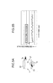
FIG. 5A is a diagram schematically illustrating the detection device according to the first embodiment of the present invention, andFIG. 5B is a graph illustrating a detection performance test result of the detection device. -
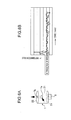
FIG. 6A is a diagram schematically illustrating a detection device according to a second embodiment of the present invention, andFIG. 6B is a graph illustrating a detection performance test result of the detection device. -
FIG. 7A is a diagram schematically illustrating a detection device according to a third embodiment of the present invention, andFIG. 7B is a graph illustrating a detection performance test result of the detection device. -
FIG. 8A is a diagram schematically illustrating a detection device according to a fourth embodiment of the present invention, andFIG. 8B is a graph illustrating a detection performance test result of the detection device. -
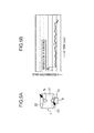
FIG. 9A is a diagram schematically illustrating a detection device according to a fifth embodiment of the present invention, andFIG. 9B is a graph illustrating a detection performance test result of the detection device. -
FIG. 10 is a front view illustrating a detection device according to another embodiment of the present invention. -
FIG. 11 is a front view illustrating a detection device according to yet another embodiment of the present invention. -
FIG. 12 is a front view illustrating a detection device according to still another embodiment of the present invention. - With reference to the accompanying drawings, embodiments of the present invention will now be described. It should be noted that the following embodiments are specific examples of the present invention but not intended to limit the technical scope of the present invention.
-
FIG. 1 is a schematic top plan view of an upper frame of a hydraulic shovel equipped with a detection device according to a first embodiment of the present invention. The following description will be made using front-rear and right-left directions as viewed from an operator seated in a seat in a cabin 2 (the left direction inFIG. 1 corresponds to a front direction, and the up direction inFIG. 1 corresponds to a right direction). - As illustrated in
FIG. 1 , a hydraulic shovel as one example of a construction machine comprises anupper frame 1, a cabin 2 provided on theupper frame 1, anengine 3, afuel tank 4, acooling fan 5, a hydraulic pump 6, and a detection device (fuel property detection device: seeFIG. 2 ) 24 for detecting a property (physical property such as kinetic viscosity or density, or chemical property) of fuel to be supplied from thefuel tank 4 to theengine 3. - The
engine 3 is disposed rearward of the cabin 2 in a posture where a longitudinal direction of theengine 3 is oriented in a right-left direction. Thefuel tank 4 is disposed on a right side of the cabin 2, and capable of storing a predetermined amount of fuel. Thecooling fan 5 is disposed on a left side of theengine 3, and adapted to be driven by a drive power of theengine 3. The hydraulic pump 6 is disposed on a right side of theengine 3, and adapted to be driven by the drive power of theengine 3. - As illustrated in
FIG. 2 , the detection device 24 comprises an inlet pipe (a part of a fuel supply pipe line) 9 connected to thefuel tank 4, an outlet pipe (a part of the fuel supply pipe line) 10 connected to theengine 3, asub-tank 7 connected to theinlet pipe 9 and theoutlet pipe 10, asensor 8 provided to thesub-tank 7, and acontroller 11 electrically connected to thesensor 8. - The
sub-tank 7 is provided in the course of a fuel supply pipe line for supplying therethrough fuel from thefuel tank 4 to the engine 3 (between theinlet pipe 9 and the outlet pipe 10). Specifically, thesub-tank 7 is capable of storing fuel by a given amount less than that (capacity) in thefuel tank 4. Further, as illustrated inFIG. 3 , a flow passage cross-sectional area E1 of thesub-tank 7 perpendicular to a fuel flow direction is greater than each of a flow passage cross-sectional area E2 of theoutlet pipe 10 perpendicular to the fuel flow direction, and a flow passage cross-sectional area E3 of theinlet pipe 9 perpendicular to the fuel flow direction. Thus, a flow velocity of fuel introduced into thesub-tank 7 becomes lower than a flow velocity of fuel in each of thepipes sub-tank 7 is stabilized. A property of the fuel reduced in flow velocity and stabilized in flow quantity in the above manner is detected by thesensor 8. - As enlargedly illustrated in
FIGS. 3 and4 , thesub-tank 7 has: asidewall 21 formed over the entire circumference around an axis J1 extending along an up-down direction; atop wall 22 closing an upper opening of thesidewall 21; abottom wall 23 closing a lower opening of thesidewall 21; afuel inlet 7a and afuel outlet 7b each formed in thesidewall 21; an air-releasingair vent port 12 formed in thetop wall 22; and aplug 13 attachable and detachable with respect to theair vent port 12. Thefuel inlet 7a is connected to theinlet pipe 9. Thefuel outlet 7b is connected to theoutlet pipe 10. - The
sidewall 21 has a cylindrical shape with the axis J1 as a central axis. Thesidewall 21 is formed with thefuel inlet 7a and thefuel outlet 7b in such a manner that they are arranged one above the other in side-by-side relation at approximately same positions in a circumferential direction about the axis J1. In other words, thefuel inlet 7a and thefuel outlet 7b are arranged one above the other in side-by-side relation on the same plane P1 (seeFIG. 4 ) along the up-down direction. Specifically, thefuel inlet 7a protrudes horizontally from a lower portion of thesidewall 21, and thefuel outlet 7b protrudes horizontally from an upper portion of thesidewall 21 at a position approximately just above thefuel inlet 7a. That is, thefuel inlet 7a and thefuel outlet 7b are arranged one above the other in side-by-side relation at approximately same positions in the circumferential direction of thesidewall 21, while extending parallel to each other. - The
sensor 8 is operable to detect the property of fuel within thesub-tank 7, and transmit a resulting detection signal to thecontroller 11 described later. More specifically, thesensor 8 comprises asensing section 8a capable of detecting a property of fuel, and asupport section 8b for supporting thesensing section 8a. Thesupport section 8b is fixed to thebottom wall 23 of thesub-tank 7 under a condition that thesensing section 8a is exposed to an inside of the sub-tank 7 through a hole formed in thebottom wall 23. For example, thesensing section 8a is configured to detect a kinetic viscosity of fuel through contact with the fuel. - The sensor 8 (
sensing section 8a) is disposed on the plane P1 (seeFIG. 4 ) including respective axes of thepipes sensor 8 and thepipes sensor 8 in the first embodiment is provided in a central portion of thebottom wall 23 of thesub-tank 7. Thus, thesensor 8 can reliably detect the property of fuel during a course after being introduced from theinlet pipe 9 through until it reaches theoutlet pipe 10. - Although the
sensor 8 in the first embodiment is provided in the central portion of thebottom wall 23 of thesub-tank 7, the present invention is not limited thereto. For example, in a situation where another structural element, such as a drain port, is provided in the central region of thebottom wall 23 of thesub-tank 7, thesensor 8 may be provided at a position offset from a center of thebottom wall 23 of the sub-tank 7 so as to prevent interference with the structural element. - The
controller 11 is electrically connected to thesensor 8, and operable, in response to receiving a detection signal from thesensor 8, to perform processing for determination, indication and alarm on adequacy of fuel. - The
air vent hole 12 is provided in a central portion of thetop wall 22 of thesub-tank 7. Theplug 13 is adapted to close theair vent port 12 under a condition that it is attached to theair vent port 12. - As described above, in the detection device 24, the
sub-tank 7 with the flow passage cross-sectional area E3 greater than each of the flow passage cross-sectional areas E2, E2 of thepipes sub-tank 7 and stabilize a flow quantity within thesub-tank 7. - In addition, the detection device 24 has the
sensor 8 capable of detecting the property of fuel reduced in flow velocity and stabilized in flow quantity in the above manner, so that it becomes possible to ensure a time required for thesensor 8 to detect the fuel property, and stabilize the fuel flow quantity, as a fundamental effect. - Furthermore, the detection device 24 has high layout flexibility during mounting on the hydraulic shovel (upper frame 1) for the following two reasons.
-
- (I) It can be installed by freely selecting an arbitrary position advantageous in avoiding interference with other device, in a space between the
fuel tank 4 and the engine 3 (in the embodiment illustrated inFIG. 1 , a rear end region of theupper frame 1 on the right side of the engine 3 (a region rearward of the hydraulic pump 6)). -
- (II) A volume of the sub-tank can be set to a minimum value for allowing the fuel flow velocity to be reduced to a value required for the fuel property detection, so that the sub-tank can be downsized.
- That is, the detection device 24 can be added on to an existing construction machine (in the first embodiment, the hydraulic shovel) and is capable of employing an in-pipeline detection system having high layout flexibility, while enhancing accuracy and stability of the fuel property detection.
- In addition to the above fundamental effect, the detection device 24 according to the first embodiment can obtain the following functions/effects.
-
- (i) In the detection device 24, the
fuel inlet 7a of thesub-tank 7 is disposed at a position closer to thesensor 8 than thefuel outlet 7b, so that fuel flows into the sub-tank 7 from a position closer to thesensor 8, which makes it possible to quickly detect a change (switching) from adequate fuel to inadequate fuel or vice versa. -
- (ii) In the detection device 24, the
fuel inlet 7a is disposed below thefuel outlet 7b, so that fuel flows into the sub-tank 7 from a relatively lower position, and, after flowing upwardly, flows out from a relatively upper position, which makes it possible to increase a speed itself of the fuel-type switching within thefuel tank 7, as compared to cases where thefuel inlet 7a and thefuel outlet 7b are arranged at the same position in the up-down direction, and more quickly detect the switching. -
- (iii) In the detection device 24, the
fuel inlet 7a and thefuel outlet 7b are arranged one above the other in side-by-side relation at approximately same positions about the up-down axis J1, so that a curved flow is formed in which fuel U-turns upwardly from the bottom side within thesub-tank 7 and flows out, as illustrated inFIG. 3 . The curved flow allows the fuel flow within thesub-tank 7 to become slower, which makes it possible to further enhance the accuracy and stability of the property detection. -
- (iv) The fuel flow becomes sufficiently slow by the curved flow, which eliminates a need for enlarging the
sub-tank 7, aiming for reducing the fuel flow velocity. This makes it possible to further downsize thesub-tank 7, and provide higher layout flexibility during mounting of the detection device 24 to the hydraulic shovel. - The
sensor 8 may be installed at a position just below a turn-around point of the U-shaped curved flow or therearound. In this case, a lowest part of the fuel in terms of the flow velocity is detected by the sensor, which provides further enhanced accuracy of the property detection. -
- (v) In the detection device 24, the
sensor 8 is disposed on the plane P1 including the axis of thefuel inlet 7a and the axis of thefuel inlet 7b, so that it becomes possible to reliably detect the property of fuel during a course after being introduced from thefuel inlet 7a through until it reaches thefuel outlet 7b. -
- (vi) In the detection device 24, the flow passage cross-sectional area E1 of the
sub-tank 7 is greater than each of the flow passage cross-sectional areas E3, E2 of theinlet pipe 9 and theoutlet pipe 10, so that it becomes possible to reliably reduce the flow velocity of fuel introduced from theinlet pipe 9 into thesub-tank 7. Thus, the accuracy of the fuel property detection can be further improved. -
FIGS. 5 to 9 are graphs illustrating respective schematic configurations of detection devices according to the first embodiment and second to fifth embodiments of the present invention, and respective detection performance test results of the detection devices. - Conditions and method for the detection performance test are as follows. A shape and a volume of the
sub-tank 7 are the same for all of the embodiments. Fuel flowing through thesub-tank 7 is changed (switched) from light oil to kerosene at a predetermined timing. A good or bad evaluation on a test result is performed based on how an output value (discrimination value) has changed over time. A timing of fuel-type switching is indicated at a left end in each ofFIGS. 5B ,6B ,7B ,8B and9B . - A flow quantity and a flow velocity of fuel to be supplied are the same for all of the embodiments. A fuel temperature within the
sub-tank 7 is changed by exogenous influences. Thus, inFIGS. 5B ,6B ,7B ,8B and9B , a discrimination value converted as a value at a fuel temperature of 30°C is indicated. - As illustrated in
FIG. 5B , in the first embodiment, the discrimination value was changed within a short period of time (2 to 3 minutes) after the fuel-type switching, and subsequently maintained at an approximately constant value. - In other words, the detection device 24 according to the first embodiment could quickly detect the fuel-type switching and obtain stable detection performance. It would be considered that the reason for this result is as follows.
- In the detection device 24, the
fuel inlet 7a and thefuel outlet 7b are arranged one above the other in side-by-side relation at approximately same positions about the up-down axis J1, and thesensor 8 is provided just below a turn-around region of the curved flow (seeFIG. 3 ) between thefuel inlet 7a and thefuel outlet 7b. Thus, according to the curved flow, fuel flows upwardly from the bottom side within thesub-tank 7, so that two types of fuels are stirred and quickly mixed together, and an oil property within thesub-tank 7 is quickly changed due to the mixing. Then, the change in oil property within thesub-tank 7 is captured by thesensor 8 quickly and accurately, so that it becomes possible to quickly detect the fuel-type switching and obtain stable detection performance. - As illustrated in
FIG. 6A , in a detection device according to the second embodiment, thefuel inlet 7a is provided at a position slightly upward of an intermediate position of thesidewall 21 of thesub-tank 7. On the other hand, in the detection device according to the second embodiment, thefuel outlet 7b is provided in thetop wall 22 of thesub-tank 7. A position of thesensor 8 in each of the second to fifth embodiments is the same as that of thesensor 8 in the first embodiment. - As illustrated in
FIG. 6B , in the detection device according to the second embodiment, although the fuel-type switching can be quickly detected, stability in the discrimination value is inferior to the first embodiment. It would be considered that the reason for this result is as follows. - In the detection device according to the second embodiment, the
fuel inlet 7a is provided in thesidewall 21 of thesub-tank 7, and thefuel outlet 7b is provided in thetop wall 22 of thesub-tank 7, so that a fuel flow within thesub-tank 7 is changed from a horizontal direction to an upward direction during a course between thefuel inlet 7a and thefuel outlet 7b. Thus, a flow around thesensor 8 is likely to be disturbed by both influences of a fuel flow introduced from thefuel inlet 7a and a fuel flow toward thefuel outlet 7b, and stability in the discrimination value becomes deteriorated due to the disturbed flow or turbulence. - As illustrated in
FIG. 7A , in a detection device according to the third embodiment, thefuel inlet 7a and thefuel outlet 7b are provided in an upper portion of thesidewall 21 of thesub-tank 7. More specifically, thefuel inlet 7a and thefuel outlet 7b are disposed at positions having approximately the same height and offset about the axis J1 by 90 degrees. - As illustrated in
FIG. 7B , in the detection device according to the third embodiment, a time required until detection of the fuel-type switching becomes longer, as compared to the first and second embodiments. It would be considered that the reason for this result is as follows. - In the detection device according to the third embodiment, both of the
fuel inlet 7a and thefuel outlet 7b are disposed at upper positions of thesub-tank 7, so that a liquid interface is formed in an upper region of the inside of thesub-tank 7. Due to the formation of the liquid interface, fuel introduced into thesub-tank 7 slowly flows in the upper region of the inside of the sub-tank 7 in a circular motion, so that mixing in the up-down direction is less likely to occur, which causes an increase in time required until detection of the fuel-type switching. - As illustrated in
FIG. 8A , in a detection device according to the fourth embodiment, thefuel inlet 7a is provided in a lower portion of thesidewall 21 of thesub-tank 7, and thefuel outlet 7b is provided in an upper portion of thesidewall 21 of thesub-tank 7. Thefuel outlet 7b is disposed at a position offset from thefuel outlet 7b about the axis J1 by 90 degrees. - As illustrated in
FIG. 8B , in the detection device according to the fourth embodiment, although the fuel-type switching can be quickly detected, the output of the discrimination value lacks stability. It would be considered that the reason for this result is as follows. - In the detection device according to the fourth embodiment, the
fuel inlet 7a and thefuel outlet 7b are positionally offset from each other in the up-down direction and further positionally offset from each other about the axis J1 by 90 degrees, so that a flow occurs in which fuel introduced into thesub-tank 7 moves from thefuel inlet 7a upwardly while being twisted toward thefuel outlet 7b. Due to influence of this flow, the output of the discrimination value lacks stability. - As illustrated in
FIG. 9A , in a detection device according to the fifth embodiment, thefuel inlet 7a is provided in a lower portion of thesidewall 21 of thesub-tank 7, and thefuel outlet 7b is provided in an upper portion of thesidewall 21 of thesub-tank 7. Further, thefuel inlet 7a and thefuel outlet 7b are disposed positionally offset from each other about the axis J1 by 180 degrees. - As illustrated in
FIG. 9B , in the detection device according to the fifth embodiment, although the fuel-type switching can be detected within a relatively short period of time, the output of the discrimination value lacks stability. It would be considered that the reason for this result is as follows. - In the detection device according to the fifth embodiment, the
fuel inlet 7a and thefuel outlet 7b are positionally offset from each other in the up-down direction and further positionally offset from each other about the axis J1 by 180 degrees, so that a flow occurs in which fuel introduced into thesub-tank 7 moves from thefuel inlet 7a upwardly toward thefuel outlet 7b. Due to influence of this flow, the output of the discrimination value lacks stability. - Considering all the above results together, among the first to fifth embodiments, the detection device according to the first embodiment is the most excellent in detection performance. This, it can be concluded that the first embodiment is the best mode among the first to fifth embodiments.
-
- (1)
FIG. 10 illustrates a detection device according to a sixth embodiment.FIG. 11 illustrated a detection device according to a seventh embodiment. In the detection device illustrated inFIG. 10 , thefuel outlet 7b is provided in an uppermost portion of thesub-tank 7. In the detection device illustrated inFIG. 11 , both of thefuel inlet 7a and thefuel outlet 7b are provided in the uppermost portion of thesub-tank 7. More specifically, in the detection device illustrated inFIG. 10 , thefuel outlet 7b is provided in an uppermost portion of thesidewall 21 of thesub-tank 7. In the detection device illustrated inFIG. 11 , both of thefuel inlet 7a and thefuel outlet 7b are provided in thetop wall 22 of thesub-tank 7. - In the detection device according to the sixth embodiment, at least the
fuel outlet 7b is provided in the uppermost portion of thesub-tank 7, so that air in fuel is led out from thesub-tank 7 through thefuel outlet 7b together with fuel without staying in thesub-tank 7. Thus, in the detection device according to the sixth embodiment, it becomes possible to eliminate a need for an air releasing operation of detaching the air vent plug 13 to open theair vent port 12, or it is only necessary to minimumly perform the operation. - Specifically, in order to simplify the air releasing operation, it is necessary that the
fuel outlet 7b is provided in the uppermost portion of thesidewall 21 of the sub-tank 7 (FIG. 10 ), or in the uppermost portion (top wall 22:FIG. 11 ) in theentire sub-tank 7. - In the detection device illustrated in
FIG. 11 , thesensor 8 is provided to theside wall 21 of thesub-tank 7. Thus, a curved flow in which fuel introduced from thefuel inlet 7a U-turns and returns to thefuel outlet 7b is generated within thesub-tank 7, and the fuel property is reliably detected by thesensor 8 in the course of the curved flow. Preferably, in the detection device illustrated inFIG. 11 , thesensor 8 is provided at a position on a lateral side of a turn-around point of the U-shaped curved flow, to the same effect as that in the first embodiment. Further, in the detection device illustrated inFIG. 11 , it is preferable that the sensor 8 (sensing section 8a) is disposed on a plane including respective axes of thefuel inlet 7a and thefuel outlet 7b, to the same effect as that in the first embodiment. -
- (2) In the above embodiments, the
sub-tank 7 is installed in a posture where the cylindrical-shapedsidewall 21 is disposed about the axis J1 extending along the up-down direction. Alternatively, as in a detection device according to an eighth embodiment illustrated inFIG. 12 , thesub-tank 7 may be installed in a posture where thesidewall 21 is disposed about an axis extending along a horizontal direction. Specifically, a laterally-oriented portion of thesidewall 21, thetop wall 22 and thebottom wall 23 make up a sidewall in the eighth embodiment. Further, an upwardly-oriented portion of thesidewall 21 makes up a top wall in the eighth embodiment, and a downwardly-oriented portion of thesidewall 21 makes up a bottom wall in the eighth embodiment. - In this case, an arrangement of the
fuel inlet 7a, thefuel outlet 7b and thesensor 8 is not limited to that illustrated inFIG. 12 , but any other suitable arrangement may be selected. - The detection device having the
sub-tank 7 horizontally disposed as illustrated inFIG. 12 can also obtain the fundamental function/effect of being able to employ the in-pipeline detection system while improving accuracy and stability of the fuel property detection, as with the first to seventh embodiments. - The above specific embodiments primarily include an invention having the following features.
- A fuel property detection device according to the above embodiments is designed to detect a property of fuel to be supplied to an engine from a fuel tank for storing fuel. The fuel property detection device comprises: a sub-tank provided in the course of a fuel supply pipeline connecting the engine and the fuel tank, and capable of storing a given amount of fuel; and a sensor provided to the sub-tank and capable of detecting the property of fuel within the sub-tank, wherein the sub-tank has a fuel inlet for introducing therethrough fuel from the fuel tank, and a fuel outlet for sending out therethrough the fuel toward the engine.
- In the fuel property detection device according to the above embodiments, the sub-tank capable of storing a given amount of fuel is provided in the course of the fuel supply pipeline, so that it becomes possible to reduce a fuel flow velocity within the sub-tank and stabilize a fuel flow quantity within the sub-tank. In addition, the fuel property detection device according to the above embodiments is provided with the sensor capable of detecting the property of fuel within the sub-tank, so that it becomes possible to ensure a time required for the detection by the sensor, and stabilize the fuel flow quantity.
- Furthermore, the sub-tank has high layout flexibility during mounting on a construction machine for the following two reasons.
-
- (I) It can be installed by freely selecting an arbitrary position advantageous in avoiding interference with other device, in a space between the fuel tank and the engine.
-
- (II) A volume of the sub-tank can be set to a minimum value for allowing the fuel flow velocity to be reduced to a value required for the fuel property detection, so that the sub-tank can be downsized.
- That is, the detection device can be added on to an existing construction machine and is capable of employing an in-pipeline detection system having high layout flexibility, while enhancing accuracy and stability of the fuel property detection.
- The term "property of fuel" means a physical property such as kinetic viscosity or density, or a chemical property of fuel.
- Preferably, in the fuel property detection device, the fuel inlet of the sub-tank is disposed at a position closer to the sensor than the fuel outlet.
- In this fuel property detection device, the fuel inlet of the sub-tank is disposed at a position closer to the sensor than the fuel outlet, so that fuel flows into the sub-tank from a position closer to the sensor, which makes it possible to quickly detect a change from adequate fuel to inadequate fuel or vice versa.
- Preferably, in the fuel property detection device, the fuel inlet is disposed below the fuel outlet.
- In this fuel property detection device, the fuel inlet is disposed below the fuel outlet, so that fuel flows into the sub-tank from a relatively lower position, and, after flowing upwardly, flows out from a relatively upper position, which makes it possible to increase a speed itself of the fuel switching within the fuel tank, as compared to cases where the fuel inlet and the fuel outlet are arranged at the same position in the up-down direction, and more quickly detect the switching.
- Preferably, the fuel inlet is capable of introducing fuel to the sub-tank in a lateral direction, and the fuel outlet is capable of leading fuel out of the sub-tank in a lateral direction, wherein the fuel inlet and the fuel outlet of the sub-tank are arranged one above the other in side-by-side relation on the same plane along an up-down direction.
- In this fuel property detection device, the fuel inlet capable of introducing fuel to the sub-tank in a lateral direction and the fuel outlet capable of leading fuel out of the sub-tank in a lateral direction are arranged one above the other in side-by-side relation on the plane along the up-down direction, so that a curved flow is formed in which fuel U-turns upwardly from the bottom side within the sub-tank and flows out.
- The curved flow allows the fuel flow within the sub-tank to become slower, which makes it possible to further enhance the accuracy and stability of the fuel property detection.
- The fuel flow becomes slow by the curved flow, which eliminates a need for enlarging the sub-tank, aiming for reducing the fuel flow velocity. This makes it possible to further downsize the sub-tank, and provide higher layout flexibility during mounting of the detection device to a construction machine.
- Preferably, in the fuel property detection device, the fuel outlet of the sub-tank is disposed in an uppermost portion of the sub-tank.
- In this fuel property detection device, the fuel outlet of the sub-tank is disposed in an uppermost portion of the sub-tank, so that air in fuel is led out from the sub-tank together with fuel without staying in the sub-tank. Thus, it becomes possible to eliminate a need for an operation for releasing air from the sub-tank, or it is only necessary to minimumly perform the operation.
- Specifically, as the sub-tank, it is possible to employ a tank which has a sidewall formed over an entire circumference about an axis along an up-down direction, a top wall closing an upper opening of the sidewall, and a bottom wall closing a lower opening of the sidewall.
- Preferably, in the above fuel property detection device, the sensor is provided to the bottom wall of the sub-tank, and the fuel inlet and fuel outlet are provided in the sidewall of the sub-tank, wherein the fuel inlet is disposed below the fuel outlet.
- In this fuel property detection device, the sensor is provided to the bottom wall of the sub-tank, and the fuel inlet is disposed below the fuel outlet, so that fuel flows into the sub-tank from a position closer to the sensor, which makes it possible to quickly detect a change from adequate fuel to inadequate fuel or vice versa.
- Preferably, in the fuel property detection device, the fuel inlet and fuel outlet of the sub-tank are arranged one above the other in side-by-side relation at approximately same positions in a circumferential direction of the sidewall.
- In this fuel property detection device, the fuel inlet and fuel outlet are arranged one above the other in side-by-side relation at approximately same positions about an axis along the up-down direction, so that a curved flow is formed in which fuel U-turns upwardly from the bottom side within the sub-tank and flows out. The curved flow allows the fuel flow within the sub-tank to become slower, which makes it possible to further enhance the accuracy and stability of the property detection. The fuel flow becomes slow by the curved flow, which eliminates a need for enlarging the sub-tank, aiming for reducing the fuel flow velocity. This makes it possible to further downsize the sub-tank, and provide higher layout flexibility during mounting of the detection device to a construction machine.
- Preferably, in the fuel property detection device, the sensor is provided to the bottom wall of the sub-tank, the fuel inlet is provided in the sidewall of the sub-tank, and fuel outlet is provided in the top wall of the sub-tank.
- In this fuel property detection device, the fuel outlet of the sub-tank is provided in the top wall of the sub-tank, so that air in fuel is led out from the sub-tank together with fuel without staying in the sub-tank. Thus, it becomes possible to eliminate a need for an operation for releasing air from the sub-tank, or it is only necessary to minimumly perform the operation.
- Preferably, in the fuel property detection device, the sensor, the fuel inlet and the fuel outlet are arranged on the same plane.
- In this fuel property detection device, the sensor, the fuel inlet and the fuel outlet are arranged on the same plane, so that it becomes possible to reliably detect the property of fuel during a course after being introduced from the fuel inlet pipe through until it reaches the fuel outlet.
- Preferably, in the fuel property detection device, the fuel property detection device comprises an inlet pipe connected to the fuel inlet of the sub-tank and connectable to the fuel tank, and an outlet pipe connected to the fuel outlet of the sub-tank and connectable to the engine, wherein a flow passage cross-sectional area of the sub-tank perpendicular to a flow direction of the fuel is greater than each of respective flow passage cross-sectional areas of the inlet pipe and the outlet pipe.
- In this fuel property detection device, the flow passage cross-sectional area of the sub-tank is greater than each of the flow passage cross-sectional areas of the inlet pipe and the outlet pipe, so that it becomes possible to reliably reduce the flow velocity of fuel introduced from the inlet pipe into the sub-tank. Thus, the accuracy of the fuel property detection can be further improved.
- Further, a construction machine according to the above embodiments comprises: the above fuel property detection device; a fuel tank connected to the inlet pipe of the fuel property detection device; and an engine connected to the outlet pipe of the fuel property detection device.
- The construction machine according to the above embodiments comprises the above fuel property detection device, so that it becomes possible to employ the in-pipeline detection system while enhancing accuracy and stability of the fuel property detection.
- The present invention makes it possible to employ the in-pipeline detection system while improving accuracy and stability of the fuel property detection.
-
- E1 to E3: flow passage cross-sectional area
- J1: axis along up-down direction
- P1: plane including axis of fuel inlet and axis of fuel outlet 3: engine
- 4: fuel tank
- 7: sub-tank
- 7a: fuel inlet
- 7b: fuel outlet
- 8: sensor
- 9: inlet pipe (part of fuel supply pipeline)
- 10: outlet pipe (part of fuel supply pipeline)
- 21: sidewall
- 22: top wall
- 23: bottom wall
- 24: detection device
Claims (12)
- A fuel property detection device for a construction machine, which is designed to detect a property of fuel to be supplied to an engine from a fuel tank for storing fuel, comprising:a sub-tank provided in the course of a fuel supply pipeline connecting the engine and the fuel tank, and capable of storing a given amount of fuel; anda sensor provided to the sub-tank and capable of detecting the property of fuel within the sub-tank,wherein the sub-tank has a fuel inlet for introducing therethrough fuel from the fuel tank, and a fuel outlet for sending out therethrough the fuel toward the engine.
- The fuel property detection device for a construction machine according to claim 1, wherein the fuel inlet of the sub-tank is disposed at a position closer to the sensor than the fuel outlet.
- The fuel property detection device for a construction machine according to claim 1 or 2, wherein the fuel inlet is disposed below the fuel outlet.
- The fuel property detection device for a construction machine according to any one of claims 1 to 3,
wherein the fuel inlet is capable of introducing fuel to the sub-tank in a lateral direction, and the fuel outlet is capable of leading fuel out of the sub-tank in a lateral direction, and
wherein the fuel inlet and the fuel outlet of the sub-tank are arranged one above the other in side-by-side relation on a same plane along an up-down direction. - The fuel property detection device for a construction machine according to claim 3, wherein the fuel outlet of the sub-tank is disposed in an uppermost portion of the sub-tank.
- The fuel property detection device for a construction machine according to claim 1, wherein the sub-tank has a sidewall formed over an entire circumference about an axis along an up-down direction, a top wall closing an upper opening of the sidewall, and a bottom wall closing a lower opening of the sidewall.
- The fuel property detection device for a construction machine according to claim 6,
wherein the sensor is provided to the bottom wall of the sub-tank, and the fuel inlet and fuel outlet are provided in the sidewall of the sub-tank, and
wherein the fuel inlet is disposed below the fuel outlet. - The fuel property detection device for a construction machine according to in claim 7, wherein the fuel inlet and fuel outlet of the sub-tank are arranged one above the other in side-by-side relation at approximately same positions in a circumferential direction of the sidewall.
- The fuel property detection device for a construction machine according to claim 6, wherein the sensor is provided to the bottom wall of the sub-tank, the fuel inlet is provided in the sidewall of the sub-tank, and fuel outlet is provided in the top wall of the sub-tank.
- The fuel property detection device for a construction machine according to any one of claims 1 to 9, wherein the sensor, the fuel inlet and the fuel outlet are arranged on a same plane.
- The fuel property detection device for a construction machine according to any one of claims 1 to 10, further comprising an inlet pipe connected to the fuel inlet of the sub-tank and connectable to the fuel tank, and an outlet pipe connected to the fuel outlet of the sub-tank and connectable to the engine, and wherein a flow passage cross-sectional area of the sub-tank perpendicular to a flow direction of the fuel is greater than each of respective flow passage cross-sectional areas of the inlet pipe and the outlet pipe.
- A construction machine comprising:the fuel property detection device for a construction machine according to claim 11;a fuel tank connected to the inlet pipe of the fuel property detection device; andan engine connected to the outlet pipe of the fuel property detection device.
Applications Claiming Priority (2)
| Application Number | Priority Date | Filing Date | Title |
|---|---|---|---|
| JP2009250034A JP5353637B2 (en) | 2009-10-30 | 2009-10-30 | Construction machine fuel property detection device |
| PCT/JP2010/006014 WO2011052139A1 (en) | 2009-10-30 | 2010-10-07 | Fuel property detection device for construction equipment and construction equipment provided therewith |
Publications (1)
| Publication Number | Publication Date |
|---|---|
| EP2495542A1 true EP2495542A1 (en) | 2012-09-05 |
Family
ID=43921576
Family Applications (1)
| Application Number | Title | Priority Date | Filing Date |
|---|---|---|---|
| EP10826276A Withdrawn EP2495542A1 (en) | 2009-10-30 | 2010-10-07 | Fuel property detection device for construction equipment and construction equipment provided therewith |
Country Status (5)
| Country | Link |
|---|---|
| US (1) | US8656765B2 (en) |
| EP (1) | EP2495542A1 (en) |
| JP (1) | JP5353637B2 (en) |
| CN (1) | CN102597736B (en) |
| WO (1) | WO2011052139A1 (en) |
Cited By (2)
| Publication number | Priority date | Publication date | Assignee | Title |
|---|---|---|---|---|
| EP2843404A1 (en) * | 2013-08-27 | 2015-03-04 | Kobelco Construction Machinery Co., Ltd. | Fuel property detection apparatus for construction machine |
| US12085216B2 (en) | 2022-02-17 | 2024-09-10 | Arctic Cat Inc. | Multi-use fuel filler tube |
Families Citing this family (3)
| Publication number | Priority date | Publication date | Assignee | Title |
|---|---|---|---|---|
| JP5984705B2 (en) | 2012-03-29 | 2016-09-06 | 愛三工業株式会社 | Fuel characteristic measuring device |
| JP2014006050A (en) * | 2012-06-21 | 2014-01-16 | Aisan Ind Co Ltd | Fuel characteristics measurement device |
| WO2015087593A1 (en) * | 2013-12-09 | 2015-06-18 | 愛三工業株式会社 | Sensor device |
Family Cites Families (22)
| Publication number | Priority date | Publication date | Assignee | Title |
|---|---|---|---|---|
| JPS62192633A (en) * | 1986-02-19 | 1987-08-24 | Ngk Spark Plug Co Ltd | Mixing ratio sensor for alcohol mixed fuel |
| DE3843177C2 (en) * | 1988-12-22 | 1999-03-25 | Fev Motorentech Gmbh & Co Kg | Procedure for determining the alcohol content and / or the calorific value of fuels |
| US4945880A (en) * | 1989-06-16 | 1990-08-07 | General Motors Corporation | Multi-fuel engine control with fuel control parameter lock |
| US4945885A (en) * | 1989-06-16 | 1990-08-07 | General Motors Corporation | Multi-fuel engine control with canister purge |
| JPH0833367B2 (en) * | 1989-11-10 | 1996-03-29 | 株式会社ユニシアジェックス | Capacitance type alcohol concentration measuring device |
| US5231358A (en) * | 1990-11-16 | 1993-07-27 | General Motors Corp. | Capacitive fuel composition sensor with slow oscillator and high speed switch |
| US5103184A (en) * | 1990-11-16 | 1992-04-07 | General Motors Corporation | Capacitive fuel composition sensor with ground isolation |
| US5261270A (en) * | 1991-08-15 | 1993-11-16 | General Motors Corporation | Fuel composition sensor diagnostic apparatus |
| JPH08145966A (en) * | 1994-11-15 | 1996-06-07 | Unisia Jecs Corp | Fuel property determination device |
| JPH0943207A (en) * | 1995-08-03 | 1997-02-14 | Unisia Jecs Corp | Fuel property determination device |
| US5945831A (en) * | 1997-06-10 | 1999-08-31 | Sargent; John S. | Volume charge density measuring system |
| JPH1113568A (en) * | 1997-06-25 | 1999-01-19 | Toyota Motor Corp | Fuel property determination device for internal combustion engine |
| US7529616B2 (en) * | 2006-03-28 | 2009-05-05 | Dresser, Inc. | Analysis of fuel combustion characteristics |
| JP4169046B2 (en) * | 2006-05-23 | 2008-10-22 | トヨタ自動車株式会社 | Control device for internal combustion engine |
| JP4915781B2 (en) * | 2006-07-05 | 2012-04-11 | 株式会社小松製作所 | Work machine fuel property detection device |
| JP4726849B2 (en) * | 2007-04-13 | 2011-07-20 | 住友建機株式会社 | Construction machine fuel discriminator |
| JP4620076B2 (en) * | 2007-04-16 | 2011-01-26 | 住友建機株式会社 | Fuel monitoring equipment for construction machinery |
| US20090153149A1 (en) * | 2007-12-12 | 2009-06-18 | Norberto Hernandez | Obstructionless inline flex fuel sensor |
| US7800379B2 (en) * | 2007-12-12 | 2010-09-21 | Delphi Technologies, Inc. | Fuel sensor |
| JP2009229129A (en) * | 2008-03-19 | 2009-10-08 | Komatsu Ltd | Property determination device of normal fuel |
| JP4711153B2 (en) * | 2009-03-12 | 2011-06-29 | 株式会社デンソー | Fuel property detection device |
| US8677819B2 (en) * | 2011-04-18 | 2014-03-25 | Parker-Hannifin Corporation | In-line fuel properties measurement unit |
-
2009
- 2009-10-30 JP JP2009250034A patent/JP5353637B2/en not_active Expired - Fee Related
-
2010
- 2010-10-07 EP EP10826276A patent/EP2495542A1/en not_active Withdrawn
- 2010-10-07 CN CN201080049450.XA patent/CN102597736B/en not_active Expired - Fee Related
- 2010-10-07 US US13/505,147 patent/US8656765B2/en not_active Expired - Fee Related
- 2010-10-07 WO PCT/JP2010/006014 patent/WO2011052139A1/en not_active Ceased
Non-Patent Citations (1)
| Title |
|---|
| See references of WO2011052139A1 * |
Cited By (2)
| Publication number | Priority date | Publication date | Assignee | Title |
|---|---|---|---|---|
| EP2843404A1 (en) * | 2013-08-27 | 2015-03-04 | Kobelco Construction Machinery Co., Ltd. | Fuel property detection apparatus for construction machine |
| US12085216B2 (en) | 2022-02-17 | 2024-09-10 | Arctic Cat Inc. | Multi-use fuel filler tube |
Also Published As
| Publication number | Publication date |
|---|---|
| CN102597736A (en) | 2012-07-18 |
| US8656765B2 (en) | 2014-02-25 |
| US20120222473A1 (en) | 2012-09-06 |
| WO2011052139A1 (en) | 2011-05-05 |
| JP2011094549A (en) | 2011-05-12 |
| JP5353637B2 (en) | 2013-11-27 |
| CN102597736B (en) | 2015-02-18 |
Similar Documents
| Publication | Publication Date | Title |
|---|---|---|
| US8656765B2 (en) | Fuel property detection device for construction machine and construction machine provided therewith | |
| CN104136725B (en) | Engine apparatus | |
| US9080490B2 (en) | Selective catalytic reduction sensor | |
| JP2012511469A (en) | Tank assembly device and vehicle with tank assembly device | |
| US11428566B2 (en) | Level sensor assembly | |
| JP2014051894A (en) | Fuel pump unit and vehicle | |
| JP2008128068A (en) | Fuel supply system | |
| EP2843404B1 (en) | Fuel property detection apparatus for construction machine | |
| CN208310935U (en) | A kind of special-shaped vibration isolation fuel tank of truck diesel alternator group | |
| JP2010179756A (en) | Fuel tank system | |
| JP5806102B2 (en) | Blowby gas recirculation device for internal combustion engine | |
| JP6424023B2 (en) | Fuel supply device | |
| JP2008155890A (en) | Fuel tank structure | |
| CN214598800U (en) | Emulsion ratio and calibration device | |
| CN108372904A (en) | Fuel oil transfer device | |
| KR101222015B1 (en) | Fuel pump module | |
| GB2525414A (en) | Fuel pump module for a fuel tank | |
| JP2010043611A (en) | Fuel filter device | |
| JP2007120414A (en) | Internal combustion engine | |
| KR20130061960A (en) | Sensor mountiong structure | |
| JP2007120413A (en) | Internal combustion engine | |
| JP2006329101A (en) | Fuel supply device | |
| JP2013151229A (en) | Fuel tank structure | |
| JP2013249784A (en) | Fuel property detecting device for construction machine | |
| JP2007211599A (en) | Lubricating oil amount detection device |
Legal Events
| Date | Code | Title | Description |
|---|---|---|---|
| PUAI | Public reference made under article 153(3) epc to a published international application that has entered the european phase |
Free format text: ORIGINAL CODE: 0009012 |
|
| 17P | Request for examination filed |
Effective date: 20120508 |
|
| AK | Designated contracting states |
Kind code of ref document: A1 Designated state(s): AL AT BE BG CH CY CZ DE DK EE ES FI FR GB GR HR HU IE IS IT LI LT LU LV MC MK MT NL NO PL PT RO RS SE SI SK SM TR |
|
| DAX | Request for extension of the european patent (deleted) | ||
| STAA | Information on the status of an ep patent application or granted ep patent |
Free format text: STATUS: THE APPLICATION HAS BEEN WITHDRAWN |
|
| 18W | Application withdrawn |
Effective date: 20150724 |