EP2495408A2 - Valve train system for an internal combustion engine - Google Patents
Valve train system for an internal combustion engine Download PDFInfo
- Publication number
- EP2495408A2 EP2495408A2 EP12156550A EP12156550A EP2495408A2 EP 2495408 A2 EP2495408 A2 EP 2495408A2 EP 12156550 A EP12156550 A EP 12156550A EP 12156550 A EP12156550 A EP 12156550A EP 2495408 A2 EP2495408 A2 EP 2495408A2
- Authority
- EP
- European Patent Office
- Prior art keywords
- exhaust
- valve
- intake
- rebreath
- lobe
- Prior art date
- Legal status (The legal status is an assumption and is not a legal conclusion. Google has not performed a legal analysis and makes no representation as to the accuracy of the status listed.)
- Withdrawn
Links
- 238000002485 combustion reaction Methods 0.000 title claims abstract description 108
- 239000000470 constituent Substances 0.000 claims abstract description 49
- RDYMFSUJUZBWLH-UHFFFAOYSA-N endosulfan Chemical compound C12COS(=O)OCC2C2(Cl)C(Cl)=C(Cl)C1(Cl)C2(Cl)Cl RDYMFSUJUZBWLH-UHFFFAOYSA-N 0.000 claims description 16
- 230000006835 compression Effects 0.000 description 9
- 238000007906 compression Methods 0.000 description 9
- 238000000034 method Methods 0.000 description 9
- 239000000446 fuel Substances 0.000 description 8
- 239000003054 catalyst Substances 0.000 description 6
- 239000000203 mixture Substances 0.000 description 5
- 230000008901 benefit Effects 0.000 description 3
- 238000010438 heat treatment Methods 0.000 description 3
- 239000012530 fluid Substances 0.000 description 2
- 238000002347 injection Methods 0.000 description 2
- 239000007924 injection Substances 0.000 description 2
- 238000005086 pumping Methods 0.000 description 2
- 230000003247 decreasing effect Effects 0.000 description 1
- 238000010790 dilution Methods 0.000 description 1
- 239000012895 dilution Substances 0.000 description 1
- 238000006073 displacement reaction Methods 0.000 description 1
- 229930195733 hydrocarbon Natural products 0.000 description 1
- 150000002430 hydrocarbons Chemical class 0.000 description 1
- 239000013618 particulate matter Substances 0.000 description 1
Images


Classifications
-
- F—MECHANICAL ENGINEERING; LIGHTING; HEATING; WEAPONS; BLASTING
- F01—MACHINES OR ENGINES IN GENERAL; ENGINE PLANTS IN GENERAL; STEAM ENGINES
- F01L—CYCLICALLY OPERATING VALVES FOR MACHINES OR ENGINES
- F01L13/00—Modifications of valve-gear to facilitate reversing, braking, starting, changing compression ratio, or other specific operations
- F01L13/0015—Modifications of valve-gear to facilitate reversing, braking, starting, changing compression ratio, or other specific operations for optimising engine performances by modifying valve lift according to various working parameters, e.g. rotational speed, load, torque
- F01L13/0021—Modifications of valve-gear to facilitate reversing, braking, starting, changing compression ratio, or other specific operations for optimising engine performances by modifying valve lift according to various working parameters, e.g. rotational speed, load, torque by modification of rocker arm ratio
-
- F—MECHANICAL ENGINEERING; LIGHTING; HEATING; WEAPONS; BLASTING
- F01—MACHINES OR ENGINES IN GENERAL; ENGINE PLANTS IN GENERAL; STEAM ENGINES
- F01L—CYCLICALLY OPERATING VALVES FOR MACHINES OR ENGINES
- F01L1/00—Valve-gear or valve arrangements, e.g. lift-valve gear
- F01L1/12—Transmitting gear between valve drive and valve
- F01L1/18—Rocking arms or levers
- F01L1/185—Overhead end-pivot rocking arms
-
- F—MECHANICAL ENGINEERING; LIGHTING; HEATING; WEAPONS; BLASTING
- F01—MACHINES OR ENGINES IN GENERAL; ENGINE PLANTS IN GENERAL; STEAM ENGINES
- F01L—CYCLICALLY OPERATING VALVES FOR MACHINES OR ENGINES
- F01L1/00—Valve-gear or valve arrangements, e.g. lift-valve gear
- F01L1/26—Valve-gear or valve arrangements, e.g. lift-valve gear characterised by the provision of two or more valves operated simultaneously by same transmitting-gear; peculiar to machines or engines with more than two lift-valves per cylinder
- F01L1/267—Valve-gear or valve arrangements, e.g. lift-valve gear characterised by the provision of two or more valves operated simultaneously by same transmitting-gear; peculiar to machines or engines with more than two lift-valves per cylinder with means for varying the timing or the lift of the valves
-
- F—MECHANICAL ENGINEERING; LIGHTING; HEATING; WEAPONS; BLASTING
- F01—MACHINES OR ENGINES IN GENERAL; ENGINE PLANTS IN GENERAL; STEAM ENGINES
- F01L—CYCLICALLY OPERATING VALVES FOR MACHINES OR ENGINES
- F01L13/00—Modifications of valve-gear to facilitate reversing, braking, starting, changing compression ratio, or other specific operations
- F01L13/0015—Modifications of valve-gear to facilitate reversing, braking, starting, changing compression ratio, or other specific operations for optimising engine performances by modifying valve lift according to various working parameters, e.g. rotational speed, load, torque
- F01L13/0036—Modifications of valve-gear to facilitate reversing, braking, starting, changing compression ratio, or other specific operations for optimising engine performances by modifying valve lift according to various working parameters, e.g. rotational speed, load, torque the valves being driven by two or more cams with different shape, size or timing or a single cam profiled in axial and radial direction
-
- F—MECHANICAL ENGINEERING; LIGHTING; HEATING; WEAPONS; BLASTING
- F02—COMBUSTION ENGINES; HOT-GAS OR COMBUSTION-PRODUCT ENGINE PLANTS
- F02D—CONTROLLING COMBUSTION ENGINES
- F02D13/00—Controlling the engine output power by varying inlet or exhaust valve operating characteristics, e.g. timing
- F02D13/02—Controlling the engine output power by varying inlet or exhaust valve operating characteristics, e.g. timing during engine operation
- F02D13/0203—Variable control of intake and exhaust valves
- F02D13/0207—Variable control of intake and exhaust valves changing valve lift or valve lift and timing
- F02D13/0211—Variable control of intake and exhaust valves changing valve lift or valve lift and timing the change of valve timing is caused by the change in valve lift, i.e. both valve lift and timing are functionally related
-
- F—MECHANICAL ENGINEERING; LIGHTING; HEATING; WEAPONS; BLASTING
- F02—COMBUSTION ENGINES; HOT-GAS OR COMBUSTION-PRODUCT ENGINE PLANTS
- F02D—CONTROLLING COMBUSTION ENGINES
- F02D13/00—Controlling the engine output power by varying inlet or exhaust valve operating characteristics, e.g. timing
- F02D13/02—Controlling the engine output power by varying inlet or exhaust valve operating characteristics, e.g. timing during engine operation
- F02D13/0203—Variable control of intake and exhaust valves
- F02D13/0215—Variable control of intake and exhaust valves changing the valve timing only
- F02D13/0219—Variable control of intake and exhaust valves changing the valve timing only by shifting the phase, i.e. the opening periods of the valves are constant
-
- F—MECHANICAL ENGINEERING; LIGHTING; HEATING; WEAPONS; BLASTING
- F02—COMBUSTION ENGINES; HOT-GAS OR COMBUSTION-PRODUCT ENGINE PLANTS
- F02D—CONTROLLING COMBUSTION ENGINES
- F02D13/00—Controlling the engine output power by varying inlet or exhaust valve operating characteristics, e.g. timing
- F02D13/02—Controlling the engine output power by varying inlet or exhaust valve operating characteristics, e.g. timing during engine operation
- F02D13/0242—Variable control of the exhaust valves only
-
- F—MECHANICAL ENGINEERING; LIGHTING; HEATING; WEAPONS; BLASTING
- F02—COMBUSTION ENGINES; HOT-GAS OR COMBUSTION-PRODUCT ENGINE PLANTS
- F02D—CONTROLLING COMBUSTION ENGINES
- F02D13/00—Controlling the engine output power by varying inlet or exhaust valve operating characteristics, e.g. timing
- F02D13/02—Controlling the engine output power by varying inlet or exhaust valve operating characteristics, e.g. timing during engine operation
- F02D13/0257—Independent control of two or more intake or exhaust valves respectively, i.e. one of two intake valves remains closed or is opened partially while the other is fully opened
-
- F—MECHANICAL ENGINEERING; LIGHTING; HEATING; WEAPONS; BLASTING
- F02—COMBUSTION ENGINES; HOT-GAS OR COMBUSTION-PRODUCT ENGINE PLANTS
- F02D—CONTROLLING COMBUSTION ENGINES
- F02D13/00—Controlling the engine output power by varying inlet or exhaust valve operating characteristics, e.g. timing
- F02D13/02—Controlling the engine output power by varying inlet or exhaust valve operating characteristics, e.g. timing during engine operation
- F02D13/0273—Multiple actuations of a valve within an engine cycle
-
- F—MECHANICAL ENGINEERING; LIGHTING; HEATING; WEAPONS; BLASTING
- F02—COMBUSTION ENGINES; HOT-GAS OR COMBUSTION-PRODUCT ENGINE PLANTS
- F02M—SUPPLYING COMBUSTION ENGINES IN GENERAL WITH COMBUSTIBLE MIXTURES OR CONSTITUENTS THEREOF
- F02M26/00—Engine-pertinent apparatus for adding exhaust gases to combustion-air, main fuel or fuel-air mixture, e.g. by exhaust gas recirculation [EGR] systems
- F02M26/01—Internal exhaust gas recirculation, i.e. wherein the residual exhaust gases are trapped in the cylinder or pushed back from the intake or the exhaust manifold into the combustion chamber without the use of additional passages
-
- F—MECHANICAL ENGINEERING; LIGHTING; HEATING; WEAPONS; BLASTING
- F01—MACHINES OR ENGINES IN GENERAL; ENGINE PLANTS IN GENERAL; STEAM ENGINES
- F01L—CYCLICALLY OPERATING VALVES FOR MACHINES OR ENGINES
- F01L2800/00—Methods of operation using a variable valve timing mechanism
- F01L2800/10—Providing exhaust gas recirculation [EGR]
-
- Y—GENERAL TAGGING OF NEW TECHNOLOGICAL DEVELOPMENTS; GENERAL TAGGING OF CROSS-SECTIONAL TECHNOLOGIES SPANNING OVER SEVERAL SECTIONS OF THE IPC; TECHNICAL SUBJECTS COVERED BY FORMER USPC CROSS-REFERENCE ART COLLECTIONS [XRACs] AND DIGESTS
- Y02—TECHNOLOGIES OR APPLICATIONS FOR MITIGATION OR ADAPTATION AGAINST CLIMATE CHANGE
- Y02T—CLIMATE CHANGE MITIGATION TECHNOLOGIES RELATED TO TRANSPORTATION
- Y02T10/00—Road transport of goods or passengers
- Y02T10/10—Internal combustion engine [ICE] based vehicles
- Y02T10/12—Improving ICE efficiencies
Definitions
- the present invention relates to a valve train system for an internal combustion engine; more particularly to a valve train system for a gasoline direct injection compression ignition (GDCI) internal combustion engine; still more particularly to a valve train system for a GDCI internal combustion engine which allows exhaust constituents to enter a combustion chamber of the internal combustion engine through an exhaust valve; and still more particularly to such a valve train system which can selectively allow exhaust constituents to enter the combustion chamber through the exhaust valve and to vary the amount of exhaust constituents that enter the combustion chamber through the exhaust valve.
- GDCI gasoline direct injection compression ignition
- GDCI gasoline direct injection compression ignition
- autoignition In order to achieve maximum fuel efficiency in a GDCI internal combustion engine, autoignition must occur over a wide range of operating loads, speeds, and temperatures. This includes using GDCI during cold starts, warm-up periods, and at light loads when autoignition using gasoline is very difficult to sustain. In order for autoignition to occur under these conditions in a GDCI internal combustion engine, special engine subsystems are needed to control conditions within the combustion chamber including pressure, temperature, air-fuel ratio, burned gas dilution, and charge motion. Additional heat may need to be added to the combustion chamber in order for the temperature therein to be sufficient to achieve autoignition.
- One method for introducing heat into the combustion chamber is to use negative valve overlap.
- camshaft phasers with large angular displacement are used to adjust the timing of the intake and exhaust valves to trap exhaust constituents in the combustion chamber by closing the exhaust valves prior to the end of the exhaust stroke.
- Conventional two-step actuation of the intake valves and exhaust valves may also be simultaneously employed to implement valve lift profiles that have been optimized for operation during negative valve overlap.
- camshaft phasers and two-step actuation of the intake valves and exhaust valves can add significant cost and complexity to the valve train system. Additionally, using negative valve overlap negatively affects pumping work of the internal combustion engine and heat of the trapped exhaust constituents can be lost to the walls of the combustion chamber.
- Another method for introducing heat into the combustion chamber is to open the intake valve during the exhaust stroke. This allows hot exhaust constituents into the intake system of the internal combustion engine which are then reintroduced into the combustion chamber during the subsequent intake stroke. This method can produce large amounts of hot residuals for mixture heating, but has the disadvantage of heating the walls of the intake port and runner.
- exhaust rebreath Yet another method for introducing heat into the combustion chamber which may be more advantageous than using negative valve overlap or opening the intake valve during the exhaust stroke is to use exhaust rebreath.
- exhaust rebreath hot exhaust constituents are introduced into the combustion chamber through the exhaust valve during the intake stroke.
- Exhaust rebreath does not compromise engine efficiency because exhaust constituents entering the cylinder during the intake stroke increases the pressure within the combustion chamber, thereby reducing the pumping loop.
- Using the exhaust rebreath method during cold starts may also reduce the time required to elevate the temperature of a catalyst in an exhaust treatment device sufficient to allow the catalyst to convert the exhaust species to less harmful constituents. This is because the exhaust temperature will be higher during exhaust rebreathing due to the decrease in intake air flow.
- the exhaust rebreath method is also helpful in maintaining temperature of the catalyst during deceleration conditions when fuel is shut off and also during low load conditions. In each of these conditions, the temperature of the catalyst may fall below the threshold required for the catalyst to convert the exhaust species to less harmful constituents.
- United Stated Patent Number 7,308,872 which is assigned to Applicant and incorporated herein by reference in its entirety teaches a valve train system which is useful in homogeneous charge compression ignition (HCCI) internal combustion engines. HCCI internal combustion engines mix air and fuel together in the intake stroke and compression of the mixture during the compression stroke will cause autoignition.
- United Stated Patent Number 7,308,872 teaches an exhaust camshaft lobe for opening and closing an exhaust lobe of the valve train system to expel exhaust constituents from the combustion chamber. A portion of the exhaust lobe profile allows the exhaust lobe to be held open for a brief time period of the intake stroke to allow a small amount of exhaust rebreath. In this way, exhaust constituents are allowed to enter the combustion chamber through the exhaust valve.
- the duration of time the exhaust valve is open during the intake stroke can be varied.
- the portion of the exhaust lobe profile that causes the exhaust rebreath is part of the main exhaust lobe that allows exhaust constituents to exit the combustion chamber, there is always some amount of rebreath of exhaust constituents.
- the rebreath event must occur at the beginning of the intake stroke while some internal combustion engines may benefit from the rebreath event occurring near the end of the intake stroke.
- valve train system that allows for varying amounts of rebreath of exhaust constituents. What is also needed is a valve train system that allows the rebreath of exhaust constituents to be discontinued when desired. What is also needed is a valve train system that allows the rebreath of exhaust constituents to occur near the end of the intake stroke.
- a valve train system for an internal combustion engine having a combustion chamber with a piston reciprocatable therewithin between a top-dead-center position and a bottom-dead-center position.
- the valve train system includes an intake valve which is moveable between an intake closed position and an intake open position for allowing a charge of at least air into the combustion chamber when the intake valve is in the intake open position.
- the intake valve is seated against an intake valve seat in the intake closed position and the intake valve is separated from the intake valve seat in the intake open position.
- the valve train system also includes a first exhaust valve moveable between an exhaust closed position and an exhaust open position for either expelling exhaust constituents from the combustion chamber or for selectively allowing exhaust constituents into the combustion chamber in the exhaust open position.
- the first exhaust valve is seated against a first exhaust valve seat in the exhaust closed position and the first exhaust valve is separated from the first exhaust valve seat in the exhaust open position.
- a camshaft includes a first main exhaust lobe for moving the first exhaust valve between the exhaust closed position and the exhaust open position for expelling exhaust constituents from the combustion chamber and a first exhaust rebreath lobe for moving the first exhaust valve between the exhaust closed position and the exhaust open position for allowing exhaust constituents into the combustion chamber.
- a first two-step device for transmitting motion from the camshaft to the first exhaust valve and is switchable between a motion transmitting position for transmitting motion from the first exhaust rebreath lobe to the first exhaust lobe and a motion preventing position for preventing motion from being transmitted from the first exhaust rebreath lobe to the first exhaust valve.
- the first exhaust rebreath lobe causes the first exhaust valve to move away from said first exhaust valve seat when said intake valve is in said intake open position and when said first two-step device is in said motion transmitting position.
- the valve train may also comprise a second exhaust valve moveable between an exhaust closed position and an exhaust open position for either expelling exhaust constituents from said combustion chamber or for selectively allowing exhaust constituents into said combustion chamber.
- the second exhaust valve is seated against a second exhaust valve seat in the exhaust closed position and the second exhaust valve is separated from the second exhaust valve seat in the exhaust open position.
- the camshaft has a second main exhaust lobe for moving the second exhaust valve between the exhaust closed position and the exhaust open position for expelling exhaust constituents from the combustion chamber and a second exhaust rebreath lobe for moving the second exhaust valve between the exhaust closed position and the exhaust open position for allowing exhaust constituents into the combustion chamber. It further comprise a second two-step device for transmitting motion from the camshaft to the second exhaust valve and being switchable between a motion transmitting position for transmitting motion from the second exhaust rebreath lobe to the second exhaust valve.
- the second exhaust rebreath lobe causes said second exhaust valve to move away from said second exhaust valve seat when said intake valve is in said intake open position and when said second two-step device in said motion transmitting position.
- the first and second two-step devices are independently switched between said motion transmitting and motion preventing positions such that one of said first and second two-step devices may be in said motion transmitting position while the other of said first and second two-step devices may be in said motion preventing position.
- the first exhaust rebreath lobe causes said first exhaust valve to move away from said first exhaust valve seat when the intake valve is moving away from said intake valve seat and said piston is moving toward said bottom dead center position.
- the phase relationship of said first exhaust rebreath lobe with the piston is variable in order to vary the time said first exhaust valve is open while the piston is moving toward said bottom dead center position, thereby varying the amount of exhaust constituents allowed into said combustion chamber.
- the first exhaust rebreath lobe causes the first exhaust valve to move away from the first exhaust valve seat when said intake valve is moving toward said intake valve seat and said piston is moving toward said bottom dead center position.
- the phase relationship of the first exhaust rebreath lobe with said piston is variable in order to vary the time the first exhaust valve is open while the piston is moving toward the bottom dead center position. Thereby it varies the amount of exhaust constituents allowed into said combustion chamber. Accordingly, the first exhaust rebreath lobe may have a different profile than said second exhaust rebreath lobe.
- the first exhaust rebreath lobe opens the first exhaust valve to a first height and the second exhaust rebreath lobe opens the second exhaust valve to a second height that is different than the first height.
- the first exhaust rebreath lobe opens the first exhaust valve for a first time duration and the second exhaust rebreath lobe opens the second exhaust valve for a second time duration that is different than the first time duration.
- the valve train system may further comprise a camshaft phaser for varying the phase relationship of the first exhaust rebreath lobe with the piston in order to vary the time the first exhaust valve is open during the intake stroke of the internal combustion engine. Thereby it is varying the time said first exhaust valve is open after the intake stroke.
- the motion transmitting position is the default position of said first two-step device.
- Fig. 1 is a schematic drawing of a four cylinder GDCI internal combustion engine in accordance with the invention
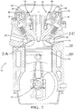
- Fig. 2 is an elevation cross-sectional view of the GDCI internal combustion engine of Fig. 1 taken through section line 2-2;
- Fig. 2A is an enlarged view of the intake valve and intake valve seat of Fig. 2 shown in the intake closed position;
- Fig. 2B is an enlarged view of the intake valve and intake valve seat of Fig. 2 shown in the intake open position;
- Fig. 2C is an enlarged view of the exhaust valve and exhaust valve seat of Fig. 2 shown in the exhaust closed position;
- Fig. 2D is an enlarged view of the exhaust valve and exhaust valve seat of Fig. 2 shown in the exhaust open position;
- Fig. 3 is an isometric view of the intake valve train of the GDCI internal combustion engine of Fig. 1 ;
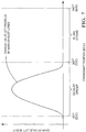
- Fig. 4 is a graph showing the intake valve lift height provided by the high lift intake lobes and the low lift intake lobes;
- Fig. 5 is an isometric view of the exhaust valve train of the GDCI internal combustion engine of Fig. 1 ;
- Fig. 6 is a graph showing the exhaust valve lift height when the two-step exhaust device is in the motion transmitting position
- Fig. 7 is a graph showing the exhaust valve lift height when the two-step exhaust device is in the motion preventing position
- Fig. 8 is a graph showing the exhaust valve lift height and the intake valve lift height when the two-step exhaust device is in the motion transmitting position and the exhaust rebreath lobe is located to open the exhaust valves at substantially the same time as the intake valve;
- Fig. 9 is a graph showing the exhaust valve lift height and the intake valve lift height when the two-step exhaust device is in the motion transmitting position and the exhaust rebreath lobe is located to close the exhaust valves at substantially the same time as the intake valve;
- Fig. 10 is a graph showing the exhaust valve lift height of two exhaust valves of a combustion chamber that have different rebreath lobe profiles.
- Fig. 11 is a graph showing the exhaust valve lift height and the intake valve lift height lobe when a camshaft phaser has been used to vary the phase relationship between the crankshaft and the exhaust camshaft to cause the exhaust valve to remain open after the intake stroke.
- GDCI internal combustion engine 10 which includes valve train system 12 for allowing at least a charge of air into combustion chamber 14 and for allowing exhaust constituents into and out of combustion chamber 14.
- Piston 16 is disposed within combustion camber 14 and is reciprocatable between a top-dead-center (TDC) position (shown as solid lines in Fig. 2 ) and a bottom dead center (BDC) position (shown as phantom lines in Fig. 2 ).
- TDC top-dead-center
- BDC bottom dead center
- a lower end of piston 16 is attached to crankshaft 18 which turns reciprocating motion of piston 16 into rotary motion.
- valve train system 12 includes first and second intake valves 20, 22 which are moveable between an intake open position as shown in Fig. 2B for allowing the charge of at least air into combustion chamber 14 and an intake closed position as shown in Figs. 2 and 2A for substantially preventing fluid communication into and out of combustion chamber 14 through first and second intake valves 20, 22.
- first and second intake valves 20, 22 are in the intake closed position, first and second intake valves 20, 22 are seated against first and second intake valve seats 24, 26 respectively.
- valve train system 12 also includes first and second exhaust valves 28, 30 which are moveable between an exhaust open position as shown in Fig. 2D and an exhaust closed position as shown in Figs. 2 and 2C .
- the exhaust open position allows exhaust constituents to be expelled from combustion chamber 14 and also selectively allows exhaust constituents into combustion chamber 14.
- the exhaust closed position substantially prevents fluid communication into and out of combustion chamber 14 through first and second exhaust valves 28, 30.
- first and second exhaust valves 28, 30 are in the exhaust closed position, first and second exhaust valves 28, 30 are seated against first and second exhaust valve seats 32, 34 respectively.
- intake camshaft 36 is provided in valve train system 12 for moving first and second intake valves 20, 22 between the intake open and intake closed positions.
- Intake camshaft 36 may include first and second center high lift intake lobes 38, 40 such that first center high lift intake lobe 38 is associated with first intake valve 20 and second center high lift intake lobe 40 is associated with second intake valve 22.
- Intake camshaft 36 may also include first and second outer low lift intake lobe pairs 42, 44 such that first center high lift intake lobe 38 is disposed between first outer low lift intake lobe pair 42 and is associated with first intake valve 20 and second center high lift intake lobe 40 is disposed between second outer low lift intake lobe pair 44 and is associated with second intake valve 22.
- First and second two-step intake devices 46, 48 may be provided to transmit motion from intake camshaft 36 to first and second intake valves 20, 22 respectively.
- An example of such first and second two-step intake devices are two-step roller finger followers as disclosed in United States Patent No. 6,668,779 which is incorporated herein by reference in its entirety.
- First and second two-step devices 46, 48 are switchable between a locked and an unlocked position. In the locked position, center intake follower 50 is held at a fixed height with respect to outer intake followers 52 which are disposed on each side of center intake follower 50. In this way, first and second center high lift intake lobes 38, 40 act on their respective center intake follower 50.
- center intake follower 50 follows the profile of its respective center high lift intake lobe 38, 40.
- center intake follower 50 follows the valve lifting portion of its center high lift intake lobe 38, 40, the two-step intake device pivots about intake lash adjuster 54, thereby lifting its respective intake valve 20, 22 from its respective intake valve seat 24, 26.
- center intake follower 50 In the unlocked position, center intake follower 50 is not held at a fixed height with respect to outer intake followers 52. As center intake follower 50 follows the valve lifting portion of its center high lift intake lobe 38, 40, center intake follower 50 is allowed to compress which is known in the art as lost motion. In this way, center intake follower 50 does not cause the two-step intake device to pivot about intake lash adjuster 54 and therefore does not impart motion on its respective intake valve 20, 22. Since center intake follower 50 is allowed to compress, outer intake followers 52 are permitted to follow the profiles of their respective outer low lift intake lobe pairs 42, 44. As intake camshaft 36 rotates, outer intake followers 52 follow the profile of their respective outer low lift intake lobe pairs 42, 44. In this way, first and second intake valves 20, 22, are moved between the intake open and intake closed positions by their respective outer low lift intake lobe pairs 42, 44 rather than by their respective center high lift intake lobe 38, 40.
- first and second outer low lift intake lobe pairs 42, 44 do not affect the position of their respective intake valves 20, 22. This is because first and second center high lift intake lobes 38, 40 produce a larger valve lift than first and second outer low lift intake lobe pairs 42, 44 and also because the valve lifting portion of first and second center high lift intake lobes 38, 40 are azimuthally located on intake camshaft 36 at substantially the same position (same crank angle positions) as first and second outer low lift intake lobe pairs 42, 44.
- Fig. 4 is a graph illustrating the height first and second intake valves are lifted from their respective intake valve seats 24, 26 in both the locked and unlocked positions during the intake stroke.
- First and second two-step intake devices 46, 48 are each provided with an intake lock mechanism (not shown). First and second two-step devices 46, 48 are placed in the unlocked position when pressurized oil from GDCI internal combustion engine 10 is supplied to the intake lock mechanism. In this way, center intake follower 50 is not held at a fixed height with respect to outer intake followers 52. First and second two-step intake devices 46, 48 are placed in the locked position when the pressurized oil is drained from the intake lock mechanism.
- the supply of pressurized oil to the intake lock mechanism for each two-step intake device 46, 48 may be controlled by first and second intake oil control valves 58, 60 respectively which both receive pressurized oil from oil supply 62.
- first and second two-step intake devices 46, 48 may both be simultaneously placed in the locked position or unlocked position or one of the first and second two-step intake devices 46, 48 may be placed in the locked position while the other of the first and second two-step intake devices 46, 48 is simultaneously in the unlocked position which may be useful, for example, for introducing swirl into combustion chamber 14 during the intake stroke of GDCI internal combustion engine 10.
- Intake camshaft 36 may be provided with intake camshaft phaser 64 for varying the phase relationship between intake camshaft 36 and crankshaft 18.
- Intake camshaft phaser 64 may be actuated by pressurized oil from oil supply 62 which is controlled by intake phasing oil control valve 66.
- intake camshaft phaser 64 may be actuated by an electric motor rather than pressurized oil.
- exhaust camshaft 68 is provided in valve train system 12 for moving first and second exhaust valves 28, 30 between the exhaust open and exhaust closed positions.
- Exhaust camshaft 68 includes first and second center exhaust rebreath lobes 70, 72 such that first center exhaust rebreath lobe 70 is associated with first exhaust valve 28 and second center exhaust rebreath lobe 72 is associated with second exhaust valve 30.
- Exhaust camshaft 68 also includes first and second outer main exhaust lobe pairs 74, 76 such that first center exhaust rebreath lobe 70 is disposed between first main exhaust lobe pair 74 and is associated with first exhaust valve 28 and second center exhaust rebreath lobe 72 is disposed between second main exhaust lobe pair 76 and is associated with second exhaust valve 30.
- First and second two-step exhaust devices 78, 80 are provided to transmit motion from exhaust camshaft 68 to first and second exhaust valves 28, 30 respectively.
- An example of such first and second two-step exhaust devices are two-step roller finger followers as disclosed in United States Patent No. 6,668,779 which is incorporated herein by reference in its entirety.
- First and second two-step exhaust devices 78, 80 are switchable between a motion transmitting position and a motion preventing position. In the motion transmitting position, center exhaust rebreath follower 82 is held at a fixed height with respect to outer main exhaust followers 84 which are disposed on each side of center exhaust rebreath follower 82.
- first and second center exhaust rebreath lobes 70, 72 act on their respective center exhaust rebreath follower 82.
- center exhaust rebreath follower 82 follows the profile of its respective center exhaust rebreath lobe 70, 72.
- the two-step exhaust device pivots about exhaust lash adjuster 86, thereby lifting its respective exhaust valve 28, 30 from its respective exhaust valve seat 32, 34.
- first and second two-step intake devices 46, 48 in which first and second outer low lift intake lobe pairs 42, 44 do not affect the position of their respective intake valves 20, 22 when center intake follower 50 is held at a fixed height with respect to outer intake followers 52, outer main exhaust followers 84 of first and second two-step exhaust devices 78, 80 do affect the position of their respective exhaust valves 28, 30.
- first and second center exhaust rebreath lobes 70, 72 produce a smaller valve lift than first and second outer main exhaust lobe pairs 74, 76 and also because the valve lifting portion of first and second center exhaust rebreath lobes 70, 72 are azimuthally located on exhaust camshaft 68 at substantially different positions (different crank angle positions) from the valve lifting portions of first and second outer main exhaust lobe pairs 74, 76 as will be discussed in more detail later.
- Fig. 6 is a graph illustrating the height first and second exhaust valves 28, 30 are lifted from their respective exhaust valve seats 32, 34 in the motion transmitting position.
- center exhaust rebreath follower 82 In the motion preventing position, center exhaust rebreath follower 82 is not held at a fixed height with respect to outer main exhaust followers 84. As center exhaust rebreath follower 82 follows the valve lifting portion of its respective center exhaust rebreath lobe 70, 72, center exhaust rebreath follower 82 is allowed to compress which is known in the art as lost motion. In this way, center exhaust rebreath follower 82 does not cause the two-step exhaust device to pivot about exhaust lash adjuster 86 and therefore does not impart motion on its respective exhaust valve 28, 30. As exhaust camshaft 68 rotates, outer main exhaust followers 84 follow the profile of their respective outer main exhaust lobes pairs 74, 76.
- first and second exhaust valves 28, 30 are moved between the exhaust open and exhaust closed positions only by their respective outer main exhaust lobe pairs 74, 76.
- Fig. 7 is a graph illustrating the height first and second valves 28, 30 are lifted from their respective exhaust valve seats 32, 34 in the motion preventing position.
- First and second two-step exhaust devices 78, 80 are each provided with an exhaust lock mechanism (not shown). First and second two-step exhaust devices 78, 80 are placed in the motion preventing position when pressurized oil from GDCI internal combustion engine 10 is supplied to the exhaust lock mechanism. In this way, center exhaust rebreath follower 82 is not held at a fixed height with respect to outer main exhaust followers 84. First and second two-step exhaust devices 78, 80 are placed in the motion transmitting position when the pressured oil is drained from the exhaust lock mechanism which may be desirable because the motion transmitting position may be the default position for first and second two-step exhaust devices 78, 80.
- first and second exhaust oil control valves 90, 92 respectively which both receive pressurized oil from oil supply 62.
- first and second two-step exhaust devices 78, 80 may both be simultaneously placed in the motion transmitting position or motion preventing position or one of the first and second two-step exhaust devices 78, 80 may be placed in the motion transmitting position while the other of the two-step exhaust devices 78, 80 may be simultaneously placed in the motion preventing position which may be useful, for example, for providing varying amounts of exhaust rebreath to combustion chamber 14.
- one of the first and second two-step exhaust devices 78, 80 may be placed in the motion transmitting position while the other of the two-step exhaust devices 78, 80 may be placed in the motion preventing position. Since only one of the first and second exhaust valves 28, 30 is opened during the intake stroke, a lesser amount exhaust constituents is introduced into combustion chamber 14 as compared to the amount of exhaust constituents that is introduced into combustion chamber 14 when both first and second two-step exhaust devices 78, 80 are placed in the motion transmitting position.
- first and second center exhaust rebreath lobes 70, 72 are azimuthally located at substantially different positions from the valve lifting portion of first and second outer main exhaust lobe pairs 74, 76.
- the valve lifting portions of first and second outer main exhaust lobe pairs 74, 76 are conventional exhaust lobes and are therefore azimuthally positioned on exhaust camshaft 68 such that first and second exhaust valves 28, 30 are in the exhaust open position when piston 16 is moving from bottom dead center to top dead center during the exhaust stroke of combustion chamber 14.
- the valve lifting portion of first and second center exhaust rebreath lobes 70, 72 are azimuthally positioned to move first and second exhaust valves 28, 30 to the exhaust open position at a different position of piston 16.
- first and second center exhaust rebreath lobes 70, 72 move first and second exhaust valves 28, 30 to the exhaust open position when piston 16 is moving from top dead center toward bottom dead center during the intake stroke of piston 16.
- exhaust constituents are introduced into combustion chamber 14 through first and second exhaust valves 28, 30 in order to add heat to combustion chamber 14 which aids in autoignition.
- first and second center exhaust rebreath lobes 70, 72 with an additional profile to produce the main exhaust event when first and second two-step exhaust devices 78, 80 are placed in the motion transmitting position.
- the main exhaust event is provided by first and second outer main exhaust lobe pairs 74, 76 which are followed by outer main exhaust followers 84 which are rollers.
- the rollers provide less friction in operation than a sliding interface such as provided by first and second center exhaust rebreath lobes 70, 72 being followed by center exhaust rebreath follower 82.
- the intake stroke of a piston is the stroke in which a charge of at least air is introduced into the combustion chamber through the intake valves.
- first and second intake valves 20, 22 are moving away from their respective intake valve seats 24, 26 during a portion of the intake stroke and first and second intake valves 20, 22 are moving toward their respective intake valve seats 24, 26 during another portion of the intake stroke.
- first and second center exhaust rebreath lobes 70, 72 may be azimuthally positioned on exhaust camshaft 68 to lift first and second exhaust valves 28, 30 from their respective exhaust valve seats 32, 34 at substantially the same time that first and second intake valves 20, 22 are lifted from their respective exhaust valve seats 32, 34. In this way, first and second exhaust valves 28, 30 move away from exhaust valve seats 32, 34 while first and second intake valves 20, 22 are moving away from first and second intake valve seats 24, 26.
- first and second center exhaust rebreath lobes 70, 72 may be azimuthally positioned to bring first and second exhaust valves 28, 30 into contact with their respective exhaust valve seats 32, 34 before first and second intake valves 20, 22 are brought into contact with their respective intake valve seats 24, 26.
- Fig. 8 is a graph illustrating the valve lift heights of first and second intake valves 20, 22 and first and second exhaust valves 28, 30 in the arrangement of this embodiment.
- first and second center exhaust rebreath lobes 70, 72 may be azimuthally positioned on exhaust camshaft 68 to bring first and second exhaust valves 28, 30 into contact with their respective exhaust valve seats 32, 34 at substantially the same time that first and second intake valves 20, 22 are brought into contact with their respective intake valve seats 24, 26.
- first and second exhaust valves 28, 30 move toward exhaust valve seats 32, 34 while first and second intake valves 20, 22 are moving toward first and second intake valve seats 24, 26.
- first and second center exhaust rebreath lobes 70, 72 may be azimuthally positioned to lift first and second exhaust valves 28, 30 from their respective exhaust valve seats 32, 34 substantially after first and second intake valves 20, 22 have been lifted from their respective intake valve seats 24, 26.
- Fig. 9 is a graph illustrating the valve lift heights of first and second intake valves 20, 22 and first and second exhaust valves 28, 30 in the arrangement of this embodiment.
- First and second center exhaust rebreath lobes 70, 72 may be substantially the same such that first and second exhaust valves 28, 30 are in the open position for the same duration of time, are opened to the same height from their respective exhaust valve seats 32, 34, and contact their respective exhaust valve seats 32, 34 at the same time.
- first and second center exhaust rebreath lobes 70, 72 may preferably be substantially different. More specifically, first and second center exhaust rebreath lobes 70, 72 may differ from each other in that they cause one of the first and second exhaust valves 28, 30 to be in the exhaust open position for a longer duration of time than the other of the first and second exhaust valves 28, 30.
- first and second center exhaust rebreath lobes 70, 72 may differ from each other in that they may cause one of the first and second exhaust valves 28, 30 to open to a height from its respective exhaust valve seat 32, 34 that is different from the height the other of the first and second exhaust valves 28, 30 is opened from is respective exhaust valve seat 32, 34.
- first and second center exhaust rebreath lobes 70, 72 may differ from each other in that they cause one of the first and second exhaust valves 28, 30 comes into contact with its respective exhaust valve seat 32, 34 at a different time than when the other of the first and second exhaust valves 28, 30 comes into contact with its respective exhaust valve seat 32, 34.
- Fig. 10 is a graph illustrating the valve lift heights of first and second exhaust valves 28, 30 in the arrangement of this embodiment.
- first and second two-step exhaust devices 78, 80 in the motion transmitting and motion preventing positions in conjunction with providing first and second center exhaust rebreath lobes 70, 72 that are substantially different from each other allows for four discrete levels of exhaust rebreath.
- a third level of exhaust rebreath is provided which is also greater than the first level of exhaust rebreath.
- the third level of exhaust rebreath may be more or less than the second level of exhaust rebreath depending on which of the center exhaust rebreath lobes 70, 72 allows more exhaust constituents into combustion chamber 14.
- a fourth level of exhaust rebreath is provided. The fourth level of exhaust rebreath is more than either the second or third levels provide individually.
- Exhaust camshaft 68 may be provided with exhaust camshaft phaser 94 for varying the phase relationship between exhaust camshaft 68 and crankshaft 18.
- Exhaust camshaft phaser 94 may be actuated by pressurized oil from oil supply 62 which is controlled by exhaust phasing oil control valve 96.
- exhaust camshaft phaser 94 may be actuated by an electric motor rather than pressurized oil.
- Using exhaust camshaft phaser 94 to vary the phase relationship between exhaust camshaft 68 and crankshaft 18 allows varying amounts of exhaust constituents to be introduced into combustion chamber 14 through first and second exhaust valves 28, 30.
- Fig. 11 is a graph illustrating the valve lift heights of first and second exhaust valves 28, 30 and first and first and second intake valves 20, 22 in the arrangement of this embodiment.
- exhaust camshaft phaser 94 By using exhaust camshaft phaser 94 to adjust the amount of time first and second exhaust valves 28, 30 are open during the intake stroke, greater control over the amount of exhaust constituents introduced into combustion chamber 14 can be realized compared to the discrete steps provided when only using first and second two-step exhaust devices 78, 80 (rebreath only by first exhaust valve 28, rebreath only by second exhaust valve 30, or rebreath by both first and second exhaust valves 28, 30)
- Exhaust camshaft phaser 94 may also be used during a cold start of GDCI internal combustion engine 10 to simultaneously advance the time first and second exhaust valves 28, 30 are opened by first and second outer main exhaust lobe pairs 74, 76. This causes early blowdown of the cylinder contents and increases exhaust temperatures during the cold start for rapid heating of catalysts in the exhaust system.
- first and second center exhaust rebreath lobes 70, 72 When exhaust camshaft phaser 94 is in the advanced position, first and second center exhaust rebreath lobes 70, 72 would be positioned such that a maximum amount of exhaust rebreath is obtained. This promotes autoignition for the coldest conditions while simultaneously providing the highest exhaust temperatures.
- exhaust camshaft phaser 94 would be retarded and exhaust rebreath levels would be decreased.
- Exhaust camshaft phasers that actuate using electric motors may be preferred for this strategy, for example, because of their high phase rate capability at low temperatures compared to exhaust camshaft phasers actuated by pressurized oil.
- GDCI internal combustion engine 10 has been illustrated as an in-line, four cylinder engine with two intake valves and two exhaust valves per cylinder, it should now be understood that other arrangements are also possible. For example internal combustion engines with other quantities of cylinders as well as internal combustion engines with include two banks of cylinders commonly referred to as "V" type arrangements.
- intake and exhaust valves for each cylinder may be used, for example, one intake valve and one exhaust valve.
- present invention may also be used in internal combustion engines that do not use the GDCI combustion strategy, for example, but not limited to, internal combustion engines which use diesel for the fuel, and gasoline engines that operate with homogeneous charge compression ignition (HCCI).
- HCCI homogeneous charge compression ignition
Landscapes
- Engineering & Computer Science (AREA)
- Mechanical Engineering (AREA)
- General Engineering & Computer Science (AREA)
- Chemical & Material Sciences (AREA)
- Combustion & Propulsion (AREA)
- Output Control And Ontrol Of Special Type Engine (AREA)
- Valve-Gear Or Valve Arrangements (AREA)
- Valve Device For Special Equipments (AREA)
Abstract
Description
- The present invention relates to a valve train system for an internal combustion engine; more particularly to a valve train system for a gasoline direct injection compression ignition (GDCI) internal combustion engine; still more particularly to a valve train system for a GDCI internal combustion engine which allows exhaust constituents to enter a combustion chamber of the internal combustion engine through an exhaust valve; and still more particularly to such a valve train system which can selectively allow exhaust constituents to enter the combustion chamber through the exhaust valve and to vary the amount of exhaust constituents that enter the combustion chamber through the exhaust valve.
- Internal combustion engines employing advanced combustion processes are being developed in order to comply with evermore stringent fuel economy requirements and restrictions on emissions such as CO2, NOx, CO, hydrocarbons, and particulate matter. One such internal combustion engine employing an advanced combustion process is known as a gasoline direct injection compression ignition (GDCI) internal combustion engine which provides the high efficiency of a diesel internal combustion engine while using regular unleaded gasoline as the fuel. The GDCI process relies on controlled autoignition of gasoline fuel in a compression ignition engine. In the GDCI process, no gasoline is injected into the combustion chamber during the intake stroke. Rather, gasoline is injected into the combustion chamber late in the compression stroke. The gasoline and air rapidly mix and compression ignites the mixture in a controlled heat release process.
- In order to achieve maximum fuel efficiency in a GDCI internal combustion engine, autoignition must occur over a wide range of operating loads, speeds, and temperatures. This includes using GDCI during cold starts, warm-up periods, and at light loads when autoignition using gasoline is very difficult to sustain. In order for autoignition to occur under these conditions in a GDCI internal combustion engine, special engine subsystems are needed to control conditions within the combustion chamber including pressure, temperature, air-fuel ratio, burned gas dilution, and charge motion. Additional heat may need to be added to the combustion chamber in order for the temperature therein to be sufficient to achieve autoignition. One method for introducing heat into the combustion chamber is to use negative valve overlap. When using negative valve overlap, camshaft phasers with large angular displacement are used to adjust the timing of the intake and exhaust valves to trap exhaust constituents in the combustion chamber by closing the exhaust valves prior to the end of the exhaust stroke. Conventional two-step actuation of the intake valves and exhaust valves may also be simultaneously employed to implement valve lift profiles that have been optimized for operation during negative valve overlap. However, such camshaft phasers and two-step actuation of the intake valves and exhaust valves can add significant cost and complexity to the valve train system. Additionally, using negative valve overlap negatively affects pumping work of the internal combustion engine and heat of the trapped exhaust constituents can be lost to the walls of the combustion chamber.
- Another method for introducing heat into the combustion chamber is to open the intake valve during the exhaust stroke. This allows hot exhaust constituents into the intake system of the internal combustion engine which are then reintroduced into the combustion chamber during the subsequent intake stroke. This method can produce large amounts of hot residuals for mixture heating, but has the disadvantage of heating the walls of the intake port and runner.
- Yet another method for introducing heat into the combustion chamber which may be more advantageous than using negative valve overlap or opening the intake valve during the exhaust stroke is to use exhaust rebreath. When using exhaust rebreath, hot exhaust constituents are introduced into the combustion chamber through the exhaust valve during the intake stroke. Exhaust rebreath does not compromise engine efficiency because exhaust constituents entering the cylinder during the intake stroke increases the pressure within the combustion chamber, thereby reducing the pumping loop. Using the exhaust rebreath method during cold starts may also reduce the time required to elevate the temperature of a catalyst in an exhaust treatment device sufficient to allow the catalyst to convert the exhaust species to less harmful constituents. This is because the exhaust temperature will be higher during exhaust rebreathing due to the decrease in intake air flow. The exhaust rebreath method is also helpful in maintaining temperature of the catalyst during deceleration conditions when fuel is shut off and also during low load conditions. In each of these conditions, the temperature of the catalyst may fall below the threshold required for the catalyst to convert the exhaust species to less harmful constituents.
- United Stated Patent Number
7,308,872 which is assigned to Applicant and incorporated herein by reference in its entirety teaches a valve train system which is useful in homogeneous charge compression ignition (HCCI) internal combustion engines. HCCI internal combustion engines mix air and fuel together in the intake stroke and compression of the mixture during the compression stroke will cause autoignition. United Stated Patent Number7,308,872 teaches an exhaust camshaft lobe for opening and closing an exhaust lobe of the valve train system to expel exhaust constituents from the combustion chamber. A portion of the exhaust lobe profile allows the exhaust lobe to be held open for a brief time period of the intake stroke to allow a small amount of exhaust rebreath. In this way, exhaust constituents are allowed to enter the combustion chamber through the exhaust valve. When used with a camshaft phaser, the duration of time the exhaust valve is open during the intake stroke can be varied. However, since the portion of the exhaust lobe profile that causes the exhaust rebreath is part of the main exhaust lobe that allows exhaust constituents to exit the combustion chamber, there is always some amount of rebreath of exhaust constituents. Additionally, the rebreath event must occur at the beginning of the intake stroke while some internal combustion engines may benefit from the rebreath event occurring near the end of the intake stroke. - What is needed is a valve train system that allows for varying amounts of rebreath of exhaust constituents. What is also needed is a valve train system that allows the rebreath of exhaust constituents to be discontinued when desired. What is also needed is a valve train system that allows the rebreath of exhaust constituents to occur near the end of the intake stroke.
- Briefly described, a valve train system is provided for an internal combustion engine having a combustion chamber with a piston reciprocatable therewithin between a top-dead-center position and a bottom-dead-center position. The valve train system includes an intake valve which is moveable between an intake closed position and an intake open position for allowing a charge of at least air into the combustion chamber when the intake valve is in the intake open position. The intake valve is seated against an intake valve seat in the intake closed position and the intake valve is separated from the intake valve seat in the intake open position. The valve train system also includes a first exhaust valve moveable between an exhaust closed position and an exhaust open position for either expelling exhaust constituents from the combustion chamber or for selectively allowing exhaust constituents into the combustion chamber in the exhaust open position. The first exhaust valve is seated against a first exhaust valve seat in the exhaust closed position and the first exhaust valve is separated from the first exhaust valve seat in the exhaust open position. A camshaft includes a first main exhaust lobe for moving the first exhaust valve between the exhaust closed position and the exhaust open position for expelling exhaust constituents from the combustion chamber and a first exhaust rebreath lobe for moving the first exhaust valve between the exhaust closed position and the exhaust open position for allowing exhaust constituents into the combustion chamber. A first two-step device is provided for transmitting motion from the camshaft to the first exhaust valve and is switchable between a motion transmitting position for transmitting motion from the first exhaust rebreath lobe to the first exhaust lobe and a motion preventing position for preventing motion from being transmitted from the first exhaust rebreath lobe to the first exhaust valve.
Also, the first exhaust rebreath lobe causes the first exhaust valve to move away from said first exhaust valve seat when said intake valve is in said intake open position and when said first two-step device is in said motion transmitting position.
The valve train may also comprise a second exhaust valve moveable between an exhaust closed position and an exhaust open position for either expelling exhaust constituents from said combustion chamber or for selectively allowing exhaust constituents into said combustion chamber. The second exhaust valve is seated against a second exhaust valve seat in the exhaust closed position and the second exhaust valve is separated from the second exhaust valve seat in the exhaust open position. The camshaft has a second main exhaust lobe for moving the second exhaust valve between the exhaust closed position and the exhaust open position for expelling exhaust constituents from the combustion chamber and a second exhaust rebreath lobe for moving the second exhaust valve between the exhaust closed position and the exhaust open position for allowing exhaust constituents into the combustion chamber. It further comprise a second two-step device for transmitting motion from the camshaft to the second exhaust valve and being switchable between a motion transmitting position for transmitting motion from the second exhaust rebreath lobe to the second exhaust valve. A motion preventing position for preventing motion from being transmitted from the second exhaust rebreath lobe to the second exhaust valve. The second exhaust rebreath lobe causes said second exhaust valve to move away from said second exhaust valve seat when said intake valve is in said intake open position and when said second two-step device in said motion transmitting position. Also, the first and second two-step devices are independently switched between said motion transmitting and motion preventing positions such that one of said first and second two-step devices may be in said motion transmitting position while the other of said first and second two-step devices may be in said motion preventing position.
In an alternative, the first exhaust rebreath lobe causes said first exhaust valve to move away from said first exhaust valve seat when the intake valve is moving away from said intake valve seat and said piston is moving toward said bottom dead center position.
The phase relationship of said first exhaust rebreath lobe with the piston is variable in order to vary the time said first exhaust valve is open while the piston is moving toward said bottom dead center position, thereby varying the amount of exhaust constituents allowed into said combustion chamber.
In another alternative, the first exhaust rebreath lobe causes the first exhaust valve to move away from the first exhaust valve seat when said intake valve is moving toward said intake valve seat and said piston is moving toward said bottom dead center position. The phase relationship of the first exhaust rebreath lobe with said piston is variable in order to vary the time the first exhaust valve is open while the piston is moving toward the bottom dead center position. Thereby it varies the amount of exhaust constituents allowed into said combustion chamber.
Accordingly, the first exhaust rebreath lobe may have a different profile than said second exhaust rebreath lobe. The first exhaust rebreath lobe opens the first exhaust valve to a first height and the second exhaust rebreath lobe opens the second exhaust valve to a second height that is different than the first height. The first exhaust rebreath lobe opens the first exhaust valve for a first time duration and the second exhaust rebreath lobe opens the second exhaust valve for a second time duration that is different than the first time duration.
The valve train system may further comprise a camshaft phaser for varying the phase relationship of the first exhaust rebreath lobe with the piston in order to vary the time the first exhaust valve is open during the intake stroke of the internal combustion engine. Thereby it is varying the time said first exhaust valve is open after the intake stroke. - Finally, the motion transmitting position is the default position of said first two-step device. Further features and advantages of the invention will appear more clearly on a reading of the following detailed description of the preferred embodiment of the invention, which is given by way of non-limiting example only and with reference to the accompanying drawings.
- This invention will be further described with reference to the accompanying drawings in which:
-
Fig. 1 is a schematic drawing of a four cylinder GDCI internal combustion engine in accordance with the invention; -
Fig. 2 is an elevation cross-sectional view of the GDCI internal combustion engine ofFig. 1 taken through section line 2-2; -
Fig. 2A is an enlarged view of the intake valve and intake valve seat ofFig. 2 shown in the intake closed position; -
Fig. 2B is an enlarged view of the intake valve and intake valve seat ofFig. 2 shown in the intake open position; -
Fig. 2C is an enlarged view of the exhaust valve and exhaust valve seat ofFig. 2 shown in the exhaust closed position; -
Fig. 2D is an enlarged view of the exhaust valve and exhaust valve seat ofFig. 2 shown in the exhaust open position; -
Fig. 3 is an isometric view of the intake valve train of the GDCI internal combustion engine ofFig. 1 ; -
Fig. 4 is a graph showing the intake valve lift height provided by the high lift intake lobes and the low lift intake lobes; -
Fig. 5 is an isometric view of the exhaust valve train of the GDCI internal combustion engine ofFig. 1 ; -
Fig. 6 is a graph showing the exhaust valve lift height when the two-step exhaust device is in the motion transmitting position; -
Fig. 7 is a graph showing the exhaust valve lift height when the two-step exhaust device is in the motion preventing position; -
Fig. 8 is a graph showing the exhaust valve lift height and the intake valve lift height when the two-step exhaust device is in the motion transmitting position and the exhaust rebreath lobe is located to open the exhaust valves at substantially the same time as the intake valve; -
Fig. 9 is a graph showing the exhaust valve lift height and the intake valve lift height when the two-step exhaust device is in the motion transmitting position and the exhaust rebreath lobe is located to close the exhaust valves at substantially the same time as the intake valve; -
Fig. 10 is a graph showing the exhaust valve lift height of two exhaust valves of a combustion chamber that have different rebreath lobe profiles; and -
Fig. 11 is a graph showing the exhaust valve lift height and the intake valve lift height lobe when a camshaft phaser has been used to vary the phase relationship between the crankshaft and the exhaust camshaft to cause the exhaust valve to remain open after the intake stroke. - In accordance with a preferred embodiment of this invention and referring to
Figs. 1 and2 , GDCIinternal combustion engine 10 is shown which includesvalve train system 12 for allowing at least a charge of air intocombustion chamber 14 and for allowing exhaust constituents into and out ofcombustion chamber 14.Piston 16 is disposed withincombustion camber 14 and is reciprocatable between a top-dead-center (TDC) position (shown as solid lines inFig. 2 ) and a bottom dead center (BDC) position (shown as phantom lines inFig. 2 ). A lower end ofpiston 16 is attached to crankshaft 18 which turns reciprocating motion ofpiston 16 into rotary motion. - Now referring to
Figs. 1 ,2 ,2A, 2B , and3 ;valve train system 12 includes first andsecond intake valves Fig. 2B for allowing the charge of at least air intocombustion chamber 14 and an intake closed position as shown inFigs. 2 and2A for substantially preventing fluid communication into and out ofcombustion chamber 14 through first andsecond intake valves second intake valves second intake valves - Now referring to
Figs. 1 ,2 ,2C, 2D and5 ;valve train system 12 also includes first andsecond exhaust valves Fig. 2D and an exhaust closed position as shown inFigs. 2 and2C . The exhaust open position allows exhaust constituents to be expelled fromcombustion chamber 14 and also selectively allows exhaust constituents intocombustion chamber 14. The exhaust closed position substantially prevents fluid communication into and out ofcombustion chamber 14 through first andsecond exhaust valves second exhaust valves second exhaust valves - Now referring to
Figs. 1 ,2 , and3 ;intake camshaft 36 is provided invalve train system 12 for moving first andsecond intake valves Intake camshaft 36 may include first and second center highlift intake lobes lift intake lobe 38 is associated withfirst intake valve 20 and second center highlift intake lobe 40 is associated withsecond intake valve 22.Intake camshaft 36 may also include first and second outer low lift intake lobe pairs 42, 44 such that first center highlift intake lobe 38 is disposed between first outer low liftintake lobe pair 42 and is associated withfirst intake valve 20 and second center highlift intake lobe 40 is disposed between second outer low liftintake lobe pair 44 and is associated withsecond intake valve 22. - First and second two-
step intake devices intake camshaft 36 to first andsecond intake valves 6,668,779 which is incorporated herein by reference in its entirety. First and second two-step devices center intake follower 50 is held at a fixed height with respect toouter intake followers 52 which are disposed on each side ofcenter intake follower 50. In this way, first and second center highlift intake lobes center intake follower 50. Asintake camshaft 36 rotates,center intake follower 50 follows the profile of its respective center highlift intake lobe center intake follower 50 follows the valve lifting portion of its center highlift intake lobe adjuster 54, thereby lifting itsrespective intake valve intake valve seat - In the unlocked position,
center intake follower 50 is not held at a fixed height with respect toouter intake followers 52. Ascenter intake follower 50 follows the valve lifting portion of its center highlift intake lobe center intake follower 50 is allowed to compress which is known in the art as lost motion. In this way,center intake follower 50 does not cause the two-step intake device to pivot about intake lashadjuster 54 and therefore does not impart motion on itsrespective intake valve center intake follower 50 is allowed to compress,outer intake followers 52 are permitted to follow the profiles of their respective outer low lift intake lobe pairs 42, 44. Asintake camshaft 36 rotates,outer intake followers 52 follow the profile of their respective outer low lift intake lobe pairs 42, 44. In this way, first andsecond intake valves lift intake lobe - It should be noted that in the locked position, first and second outer low lift intake lobe pairs 42, 44 do not affect the position of their
respective intake valves lift intake lobes lift intake lobes intake camshaft 36 at substantially the same position (same crank angle positions) as first and second outer low lift intake lobe pairs 42, 44.Fig. 4 is a graph illustrating the height first and second intake valves are lifted from their respective intake valve seats 24, 26 in both the locked and unlocked positions during the intake stroke. - First and second two-
step intake devices step devices internal combustion engine 10 is supplied to the intake lock mechanism. In this way,center intake follower 50 is not held at a fixed height with respect toouter intake followers 52. First and second two-step intake devices step intake device oil control valves oil supply 62. In this way, first and second two-step intake devices step intake devices step intake devices combustion chamber 14 during the intake stroke of GDCIinternal combustion engine 10. -
Intake camshaft 36 may be provided withintake camshaft phaser 64 for varying the phase relationship betweenintake camshaft 36 andcrankshaft 18.Intake camshaft phaser 64 may be actuated by pressurized oil fromoil supply 62 which is controlled by intake phasingoil control valve 66. Alternatively, but not shown,intake camshaft phaser 64 may be actuated by an electric motor rather than pressurized oil. - Now referring to
Figs. 1 ,2 , and5 ;exhaust camshaft 68 is provided invalve train system 12 for moving first andsecond exhaust valves Exhaust camshaft 68 includes first and second centerexhaust rebreath lobes exhaust rebreath lobe 70 is associated withfirst exhaust valve 28 and second centerexhaust rebreath lobe 72 is associated withsecond exhaust valve 30.Exhaust camshaft 68 also includes first and second outer main exhaust lobe pairs 74, 76 such that first centerexhaust rebreath lobe 70 is disposed between first mainexhaust lobe pair 74 and is associated withfirst exhaust valve 28 and second centerexhaust rebreath lobe 72 is disposed between second mainexhaust lobe pair 76 and is associated withsecond exhaust valve 30. - First and second two-
step exhaust devices exhaust camshaft 68 to first andsecond exhaust valves 6,668,779 which is incorporated herein by reference in its entirety. First and second two-step exhaust devices exhaust rebreath follower 82 is held at a fixed height with respect to outermain exhaust followers 84 which are disposed on each side of centerexhaust rebreath follower 82. In this way, first and second centerexhaust rebreath lobes exhaust rebreath follower 82. Asexhaust camshaft 68 rotates, centerexhaust rebreath follower 82 follows the profile of its respective centerexhaust rebreath lobe exhaust rebreath follower 82 follows the valve lifting portion of its respective centerexhaust rebreath lobe adjuster 86, thereby lifting itsrespective exhaust valve exhaust valve seat step intake devices respective intake valves center intake follower 50 is held at a fixed height with respect toouter intake followers 52, outermain exhaust followers 84 of first and second two-step exhaust devices respective exhaust valves exhaust rebreath lobes exhaust rebreath lobes exhaust camshaft 68 at substantially different positions (different crank angle positions) from the valve lifting portions of first and second outer main exhaust lobe pairs 74, 76 as will be discussed in more detail later.Fig. 6 is a graph illustrating the height first andsecond exhaust valves - In the motion preventing position, center
exhaust rebreath follower 82 is not held at a fixed height with respect to outermain exhaust followers 84. As centerexhaust rebreath follower 82 follows the valve lifting portion of its respective centerexhaust rebreath lobe exhaust rebreath follower 82 is allowed to compress which is known in the art as lost motion. In this way, centerexhaust rebreath follower 82 does not cause the two-step exhaust device to pivot about exhaust lashadjuster 86 and therefore does not impart motion on itsrespective exhaust valve exhaust camshaft 68 rotates, outermain exhaust followers 84 follow the profile of their respective outer main exhaust lobes pairs 74, 76. In this way, first andsecond exhaust valves Fig. 7 is a graph illustrating the height first andsecond valves - First and second two-
step exhaust devices step exhaust devices internal combustion engine 10 is supplied to the exhaust lock mechanism. In this way, centerexhaust rebreath follower 82 is not held at a fixed height with respect to outermain exhaust followers 84. First and second two-step exhaust devices step exhaust devices internal combustion engine 10 which may be desirable for operating a cold engine. The supply of pressurized oil to the exhaust lock mechanism for each two-step exhaust device oil control valves oil supply 62. In this way, first and second two-step exhaust devices step exhaust devices step exhaust devices combustion chamber 14. More specifically, if a lesser amount of rebreath is desired, one of the first and second two-step exhaust devices step exhaust devices second exhaust valves combustion chamber 14 as compared to the amount of exhaust constituents that is introduced intocombustion chamber 14 when both first and second two-step exhaust devices - As mentioned previously, the valve lifting portion of first and second center
exhaust rebreath lobes exhaust camshaft 68 such that first andsecond exhaust valves piston 16 is moving from bottom dead center to top dead center during the exhaust stroke ofcombustion chamber 14. However, the valve lifting portion of first and second centerexhaust rebreath lobes second exhaust valves piston 16. Specifically, first and second centerexhaust rebreath lobes second exhaust valves piston 16 is moving from top dead center toward bottom dead center during the intake stroke ofpiston 16. In this way, exhaust constituents are introduced intocombustion chamber 14 through first andsecond exhaust valves combustion chamber 14 which aids in autoignition. - It should be noted that friction benefits can be realized by not providing first and second center
exhaust rebreath lobes step exhaust devices main exhaust followers 84 which are rollers. The rollers provide less friction in operation than a sliding interface such as provided by first and second centerexhaust rebreath lobes exhaust rebreath follower 82. - As is well known in the art of internal combustion engines, the intake stroke of a piston is the stroke in which a charge of at least air is introduced into the combustion chamber through the intake valves. As is also well known in the art of internal combustion engines, first and
second intake valves second intake valves exhaust rebreath lobes exhaust camshaft 68 to lift first andsecond exhaust valves second intake valves second exhaust valves second intake valves exhaust rebreath lobes second exhaust valves second intake valves Fig. 8 is a graph illustrating the valve lift heights of first andsecond intake valves second exhaust valves - In another preferred embodiment, the valve lifting portion of first and second center
exhaust rebreath lobes exhaust camshaft 68 to bring first andsecond exhaust valves second intake valves second exhaust valves second intake valves exhaust rebreath lobes second exhaust valves second intake valves Fig. 9 is a graph illustrating the valve lift heights of first andsecond intake valves second exhaust valves - First and second center
exhaust rebreath lobes second exhaust valves exhaust rebreath lobes exhaust rebreath lobes second exhaust valves second exhaust valves exhaust rebreath lobes second exhaust valves exhaust valve seat second exhaust valves exhaust valve seat exhaust rebreath lobes second exhaust valves exhaust valve seat second exhaust valves exhaust valve seat Fig. 10 is a graph illustrating the valve lift heights of first andsecond exhaust valves - As should now be clear, the ability to independently place first and second two-
step exhaust devices exhaust rebreath lobes step exhaust devices step exhaust device 78 is placed in the motion transmitting position while second exhaust two-step device 80 is placed in the motion preventing position, a second level of exhaust rebreath is provided which is greater than the first level of exhaust rebreath. Third, when first exhaust two-step device 78 is placed in the motion preventing position while second exhaust two-step device 80 is placed in the motion transmitting position, a third level of exhaust rebreath is provided which is also greater than the first level of exhaust rebreath. The third level of exhaust rebreath may be more or less than the second level of exhaust rebreath depending on which of the centerexhaust rebreath lobes combustion chamber 14. Fourth, when both first and second two-step exhaust devices -
Exhaust camshaft 68 may be provided withexhaust camshaft phaser 94 for varying the phase relationship betweenexhaust camshaft 68 andcrankshaft 18.Exhaust camshaft phaser 94 may be actuated by pressurized oil fromoil supply 62 which is controlled by exhaust phasingoil control valve 96. Alternatively, but not shown,exhaust camshaft phaser 94 may be actuated by an electric motor rather than pressurized oil. Usingexhaust camshaft phaser 94 to vary the phase relationship betweenexhaust camshaft 68 andcrankshaft 18 allows varying amounts of exhaust constituents to be introduced intocombustion chamber 14 through first andsecond exhaust valves exhaust camshaft 68 andcrankshaft 18 such that first andsecond exhaust valves second exhaust valves piston 16 is moving toward the top dead center position after the intake stroke is complete. In this way, exhaust constituents can no longer be introduced intocombustion chamber 14 because the movement ofpiston 16 is acting to push contents ofcombustion chamber 14 out through first andsecond exhaust valves Fig. 11 is a graph illustrating the valve lift heights of first andsecond exhaust valves second intake valves exhaust camshaft phaser 94 to adjust the amount of time first andsecond exhaust valves combustion chamber 14 can be realized compared to the discrete steps provided when only using first and second two-step exhaust devices 78, 80 (rebreath only byfirst exhaust valve 28, rebreath only bysecond exhaust valve 30, or rebreath by both first andsecond exhaust valves 28, 30) -
Exhaust camshaft phaser 94 may also be used during a cold start of GDCIinternal combustion engine 10 to simultaneously advance the time first andsecond exhaust valves exhaust camshaft phaser 94 is in the advanced position, first and second centerexhaust rebreath lobes internal combustion engine 10 warms up,exhaust camshaft phaser 94 would be retarded and exhaust rebreath levels would be decreased. Exhaust camshaft phasers that actuate using electric motors may be preferred for this strategy, for example, because of their high phase rate capability at low temperatures compared to exhaust camshaft phasers actuated by pressurized oil. While GDCIinternal combustion engine 10 has been illustrated as an in-line, four cylinder engine with two intake valves and two exhaust valves per cylinder, it should now be understood that other arrangements are also possible. For example internal combustion engines with other quantities of cylinders as well as internal combustion engines with include two banks of cylinders commonly referred to as "V" type arrangements. It should also now be understood that other quantities of intake and exhaust valves for each cylinder may be used, for example, one intake valve and one exhaust valve. Furthermore, the present invention may also be used in internal combustion engines that do not use the GDCI combustion strategy, for example, but not limited to, internal combustion engines which use diesel for the fuel, and gasoline engines that operate with homogeneous charge compression ignition (HCCI).
Claims (14)
- A valve train system (12) for an internal combustion engine (10) having a combustion chamber (14) with a piston (16) reciprocatable therewithin between a top-dead-center (TDC) position and a bottom-dead-center (BDC) position, said valve train system (12) comprising:an intake valve (20) moveable between an intake closed position and an intake open position for allowing a charge of at least air into said combustion chamber (14) in said intake open position, wherein said intake valve (20) is seated against an intake valve seat (24) in said intake closed position and said intake valve (20) is separated from said intake valve seat (24) in said intake open position;a first exhaust valve (28) moveable between an exhaust closed position and an exhaust open position for either expelling exhaust constituents from said combustion chamber (14) or for selectively allowing exhaust constituents into said combustion chamber (14) in said exhaust open position, wherein said first exhaust valve (28) is seated against a first exhaust valve seat (32) in said exhaust closed position and said first exhaust valve (28) is separated from said first exhaust valve seat (32) in said exhaust open position;a camshaft (36) with a first main exhaust lobe for moving said first exhaust valve (28) between said exhaust closed position and said exhaust open position for expelling exhaust constituents from said combustion chamber (14) and a first exhaust rebreath lobe for moving said first exhaust valve (28) between said exhaust closed position and said exhaust open position for allowing exhaust constituents into said combustion chamber (14); anda first two-step device (46) for transmitting motion from said camshaft (36) to said first exhaust valve (28) and being switchable between a motion transmitting position for transmitting motion from said first exhaust rebreath lobe to said first exhaust valve (28) and a motion preventing position for preventing motion from being transmitted from said first exhaust rebreath lobe to said first exhaust valve (28).
- A valve train system (12) as in claim 1 wherein said first exhaust rebreath lobe causes said first exhaust valve (28) to move away from said first exhaust valve seat (32) when said intake valve (20) is in said intake open position and when said first two-step device is in said motion transmitting position.
- A valve train system (12) as set in any of the preceding claim further comprising:a second exhaust valve (30) moveable between an exhaust closed position and an exhaust open position for either expelling exhaust constituents from said combustion chamber (14) or for selectively allowing exhaust constituents into said combustion chamber (14), wherein said second exhaust valve (30) is seated against a second exhaust valve seat (34) in said exhaust closed position and said second exhaust valve (30) is separated from said second exhaust valve seat (34) in said exhaust open position, and wherein said camshaft (36) has a second main exhaust lobe for moving said second exhaust valve (30) between said exhaust closed position and said exhaust open position for expelling exhaust constituents from said combustion chamber (14) and a second exhaust rebreath lobe for moving said second exhaust valve (30) between said exhaust closed position and said exhaust open position for allowing exhaust constituents into said combustion chamber (14); anda second two-step device (48) for transmitting motion from said camshaft (36) to said second exhaust valve (30) and being switchable between a motion transmitting position for transmitting motion from said second exhaust rebreath lobe to said second exhaust valve (30) and a motion preventing position for preventing motion from being transmitted from said second exhaust rebreath lobe to said second exhaust valve (30).
- A valve train system (12) as in claim 3 wherein said second exhaust rebreath lobe causes said second exhaust valve (30) to move away from said second exhaust valve seat (34) when said intake valve (20) is in said intake open position and when said second two-step device (48) in said motion transmitting position.
- A valve train system (12) as in any of the claim 3 or 4 wherein said first and second two-step devices (46, 48) are independently switched between said motion transmitting and motion preventing positions such that one of said first and second two-step devices may be in said motion transmitting position while the other of said first and second two-step devices may be in said motion preventing position.
- A valve train system (12) as set in any of the preceding claim wherein said first exhaust rebreath lobe causes said first exhaust valve (28) to move away from said first exhaust valve seat (32) when said intake valve (20) is moving away from said intake valve seat (24) and said piston (16) is moving toward said bottom dead center position.
- A valve train system (12) as in claim 6 wherein the phase relationship of said first exhaust rebreath lobe with said piston (16) is variable in order to vary the time said first exhaust valve (28) is open while said piston (16) is moving toward said bottom dead center position, thereby varying the amount of exhaust constituents allowed into said combustion chamber (14).
- A valve train system (12) as set in any of the preceding claim wherein said first exhaust rebreath lobe causes said first exhaust valve (28) to move away from said first exhaust valve seat (32) when said intake valve (20) is moving toward said intake valve seat (24) and said piston is moving toward said bottom dead center position.
- A valve train system (12) as in claim 8 wherein the phase relationship of said first exhaust rebreath lobe with said piston (16) is variable in order to vary the time said first exhaust valve (28) is open while said piston (16) is moving toward said bottom dead center position, thereby varying the amount of exhaust constituents allowed into said combustion chamber (14).
- A valve train system (12) as set in any of the claim 3 to 5 wherein said first exhaust rebreath lobe has a different profile than said second exhaust rebreath lobe.
- A valve train system (12) as in claim 10 wherein said first exhaust rebreath lobe opens said first exhaust valve (28) to a first height and said second exhaust rebreath lobe opens said second exhaust valve (30) to a second height that is different than said first height.
- A valve train system (12) as set in any of the claim 10 or 11 wherein said first exhaust rebreath lobe opens said first exhaust valve (28) for a first time duration and said second exhaust rebreath lobe opens said second exhaust valve (30) for a second time duration that is different than said first time duration.
- A valve train system (12) as set in any of the preceding claim further comprising a camshaft phaser (64) for varying the phase relationship of said first exhaust rebreath lobe with said piston (16) in order to vary the time said first exhaust valve (28) is open during the intake stroke of said internal combustion engine (10), thereby varying the time said first exhaust valve (28) is open after the intake stroke.
- A valve train system (12) as set in any of the preceding claim wherein said motion transmitting position is the default position of said first two-step device (46).
Applications Claiming Priority (1)
| Application Number | Priority Date | Filing Date | Title |
|---|---|---|---|
| US13/038,418 US9765658B2 (en) | 2011-03-02 | 2011-03-02 | Valve train system for an internal combustion engine |
Publications (2)
| Publication Number | Publication Date |
|---|---|
| EP2495408A2 true EP2495408A2 (en) | 2012-09-05 |
| EP2495408A3 EP2495408A3 (en) | 2013-02-06 |
Family
ID=45656448
Family Applications (1)
| Application Number | Title | Priority Date | Filing Date |
|---|---|---|---|
| EP12156550A Withdrawn EP2495408A3 (en) | 2011-03-02 | 2012-02-22 | Valve train system for an internal combustion engine |
Country Status (3)
| Country | Link |
|---|---|
| US (1) | US9765658B2 (en) |
| EP (1) | EP2495408A3 (en) |
| JP (1) | JP2012180832A (en) |
Cited By (4)
| Publication number | Priority date | Publication date | Assignee | Title |
|---|---|---|---|---|
| WO2017060492A1 (en) * | 2015-10-07 | 2017-04-13 | Eaton Srl | Valve train assembly |
| FR3044359A1 (en) * | 2015-12-01 | 2017-06-02 | Renault Sas | METHOD FOR CONTROLLING AN INTERNAL COMBUSTION ENGINE |
| EP3063396A4 (en) * | 2013-10-31 | 2017-07-05 | Delphi Technologies, Inc. | Cold start strategy and system for gasoline direct injection compression ignition engine |
| EP3667037A1 (en) * | 2018-12-14 | 2020-06-17 | Deere & Company | Valve train with switchable engine braking |
Families Citing this family (13)
| Publication number | Priority date | Publication date | Assignee | Title |
|---|---|---|---|---|
| JP6170711B2 (en) * | 2013-04-12 | 2017-07-26 | 日立オートモティブシステムズ株式会社 | Variable valve operating device for internal combustion engine |
| EP2986836A4 (en) * | 2013-04-16 | 2016-12-14 | Delphi Tech Inc | Piston and bowl for gasoline direct injection compression ignition (gdci) |
| US20190226419A1 (en) * | 2014-10-23 | 2019-07-25 | Xiangjin Zhou | Hybrid combustion mode of internal combustion engine and controller thereof, internal combustion engine, and automobile |
| AT516543B1 (en) * | 2014-12-19 | 2021-01-15 | Innio Jenbacher Gmbh & Co Og | Method for operating a spark-ignited internal combustion engine |
| CN108138608A (en) * | 2015-08-05 | 2018-06-08 | 伊顿智能动力有限公司 | For the switching rocking arm of internal exhaust gas recirculation |
| DE112017000256T5 (en) * | 2016-01-19 | 2018-09-27 | Eaton Intelligent Power Limited | Airflow management strategies for a diesel engine |
| US11199162B2 (en) | 2016-01-19 | 2021-12-14 | Eaton Intelligent Power Limited | In-cylinder EGR and VVA for aftertreatment temperature control |
| US10221779B2 (en) | 2016-12-16 | 2019-03-05 | Ford Global Technologies, Llc | System and method for providing EGR to an engine |
| JP6965616B2 (en) * | 2017-07-27 | 2021-11-10 | 株式会社Ihi | 4-cycle engine |
| US10472998B2 (en) | 2018-02-16 | 2019-11-12 | Delphi Technologies Ip Limited | Switchable rocker arm with lash adjustment |
| DE102018105359A1 (en) * | 2018-03-08 | 2019-09-12 | Man Truck & Bus Ag | Variable valve train with sliding cam system for an internal combustion engine |
| US10519817B1 (en) | 2018-08-29 | 2019-12-31 | Delphi Technologies Ip Limited | Switchable rocker arm with lash adjustment and travel stop |
| US10954869B1 (en) * | 2020-02-18 | 2021-03-23 | Ford Global Technologies, Llc | System and method to reduce engine hydrocarbon emissions |
Citations (2)
| Publication number | Priority date | Publication date | Assignee | Title |
|---|---|---|---|---|
| US6668779B2 (en) | 2002-05-08 | 2003-12-30 | Delphi Technologies, Inc. | Two-step finger follower rocker arm assembly |
| US7308872B2 (en) | 2004-12-30 | 2007-12-18 | Delphi Technologies, Inc. | Method and apparatus for optimized combustion in an internal combustion engine utilizing homogeneous charge compression ignition and variable valve actuation |
Family Cites Families (23)
| Publication number | Priority date | Publication date | Assignee | Title |
|---|---|---|---|---|
| JP2002541382A (en) | 1999-04-14 | 2002-12-03 | ディーゼル エンジン リターダーズ,インコーポレイテッド | Exhaust and intake rocker arm assembly for correcting valve lift and valve timing during positive power |
| JP3835142B2 (en) * | 1999-09-07 | 2006-10-18 | 日産自動車株式会社 | Control device for self-ignition / spark ignition internal combustion engine |
| GB2378729A (en) | 2001-08-18 | 2003-02-19 | Mechadyne Plc | Adjustable engine valve control system |
| SE521189C2 (en) | 2002-02-04 | 2003-10-07 | Volvo Lastvagnar Ab | Device for supplying EGR gas |
| ITTO20020377A1 (en) | 2002-05-07 | 2003-11-07 | Iveco Motorenforschung Ag | VALVE ACTUATION SYSTEM FOR INTERNAL COMBUSTION ENGINE EXHAUST RECIRCULATION SYSTEM. |
| US7093568B2 (en) * | 2003-01-13 | 2006-08-22 | Ford Global Technologies, Llc | Control of autoignition timing in a HCCI engine |
| US6983732B2 (en) * | 2003-07-01 | 2006-01-10 | General Motors Corporation | Injection strategy for operating a direct-injection controlled auto-ignition four-stroke internal combustion engine |
| JP2005105954A (en) | 2003-09-30 | 2005-04-21 | Fuso Engineering Corp | Engine |
| US7128062B2 (en) * | 2004-07-12 | 2006-10-31 | General Motors Corporation | Method for mid load operation of auto-ignition combustion |
| CN1839250B (en) | 2004-07-17 | 2011-01-05 | 玛勒阀门有限公司 | Controllers for valves, especially gas exchange valves of internal combustion engines |
| US7152559B2 (en) * | 2004-07-26 | 2006-12-26 | General Motors Corporation | Valve and fueling strategy for operating a controlled auto-ignition four-stroke internal combustion engine |
| US7021277B2 (en) * | 2004-07-26 | 2006-04-04 | General Motors Corporation | Valve and fueling strategy for operating a controlled auto-ignition four-stroke internal combustion engine |
| WO2006023098A2 (en) * | 2004-07-26 | 2006-03-02 | General Motors Corporation | NOx EMISSION CONTROL FOR A CONTROLLED AUTO-IGNITION FOUR-SRTOKE INTERNAL COMBUSTION ENGINE |
| JP4523971B2 (en) | 2004-09-09 | 2010-08-11 | ボルボ ラストバグナー アーベー | Internal combustion engine equipment |
| GB2418744B (en) | 2004-09-30 | 2009-04-01 | Mahle Powertrain Ltd | Exhaust gas recirculation |
| JP4124224B2 (en) * | 2005-11-14 | 2008-07-23 | トヨタ自動車株式会社 | Control device for four-cycle premixed compression self-ignition internal combustion engine |
| US7162983B1 (en) | 2006-02-22 | 2007-01-16 | Gm Global Technology Operations, Inc. | Valve actuator assembly for variable displacement of an engine valve |
| GB2447466B (en) | 2007-03-13 | 2011-11-16 | Mechadyne Plc | Variable valve actuation system for an internal combustion engine |
| US7798126B2 (en) * | 2007-08-17 | 2010-09-21 | Gm Global Technology Operations, Inc. | Method for controlling cylinder charge in a homogeneous charge compression ignition engine |
| JP5331343B2 (en) | 2007-12-27 | 2013-10-30 | ダイムラー・アクチェンゲゼルシャフト | Variable valve operating device for internal combustion engine |
| US8118002B2 (en) | 2008-02-19 | 2012-02-21 | Delphi Technologies, Inc. | Continuously variable valve lift system including valve deactivation capability on one of two dual intake valves |
| US7934477B2 (en) | 2008-08-25 | 2011-05-03 | GM Global Technology Operations LLC | Rocker arm assembly |
| EP2653673A1 (en) | 2012-04-19 | 2013-10-23 | Eaton S.r.l. | A switchable rocker arm |
-
2011
- 2011-03-02 US US13/038,418 patent/US9765658B2/en active Active
-
2012
- 2012-02-22 EP EP12156550A patent/EP2495408A3/en not_active Withdrawn
- 2012-02-29 JP JP2012042865A patent/JP2012180832A/en active Pending
Patent Citations (2)
| Publication number | Priority date | Publication date | Assignee | Title |
|---|---|---|---|---|
| US6668779B2 (en) | 2002-05-08 | 2003-12-30 | Delphi Technologies, Inc. | Two-step finger follower rocker arm assembly |
| US7308872B2 (en) | 2004-12-30 | 2007-12-18 | Delphi Technologies, Inc. | Method and apparatus for optimized combustion in an internal combustion engine utilizing homogeneous charge compression ignition and variable valve actuation |
Cited By (5)
| Publication number | Priority date | Publication date | Assignee | Title |
|---|---|---|---|---|
| EP3063396A4 (en) * | 2013-10-31 | 2017-07-05 | Delphi Technologies, Inc. | Cold start strategy and system for gasoline direct injection compression ignition engine |
| WO2017060492A1 (en) * | 2015-10-07 | 2017-04-13 | Eaton Srl | Valve train assembly |
| FR3044359A1 (en) * | 2015-12-01 | 2017-06-02 | Renault Sas | METHOD FOR CONTROLLING AN INTERNAL COMBUSTION ENGINE |
| EP3667037A1 (en) * | 2018-12-14 | 2020-06-17 | Deere & Company | Valve train with switchable engine braking |
| US10927714B2 (en) | 2018-12-14 | 2021-02-23 | Deere & Company | Valve train with switchable engine braking |
Also Published As
| Publication number | Publication date |
|---|---|
| US20120222639A1 (en) | 2012-09-06 |
| JP2012180832A (en) | 2012-09-20 |
| US9765658B2 (en) | 2017-09-19 |
| EP2495408A3 (en) | 2013-02-06 |
Similar Documents
| Publication | Publication Date | Title |
|---|---|---|
| US9765658B2 (en) | Valve train system for an internal combustion engine | |
| US7308872B2 (en) | Method and apparatus for optimized combustion in an internal combustion engine utilizing homogeneous charge compression ignition and variable valve actuation | |
| JP4957611B2 (en) | Control method for internal combustion engine | |
| US7819100B2 (en) | Internal combustion engine with intake valves having a variable actuation and a lift profile including a constant lift boot portion | |
| US8375904B2 (en) | Early intake valve closing and variable valve timing assembly and method | |
| US8235013B2 (en) | Internal combustion engine | |
| JP2008545084A (en) | Variable valve mechanism for piston internal combustion engine | |
| JPH10252513A (en) | Method for controlling self-ignition in 4-stroke engine | |
| US8479509B2 (en) | Internal combustion engine | |
| US8316809B1 (en) | Two-mode valve actuator system for a diesel engine | |
| US8096281B2 (en) | Diesel engine having a system for variable control of the intake valves and internal exhaust-gas recirculation | |
| US7258100B2 (en) | Internal combustion engine control | |
| US20030121484A1 (en) | Continuously variable valve timing, lift and duration for internal combustion engine | |
| JP6131840B2 (en) | Control device for compression ignition engine | |
| EP1512863B1 (en) | Method and intake cam for retaining exhaust residuals for emissions reduction in a diesel engine | |
| JP5589906B2 (en) | gasoline engine | |
| KR20220030299A (en) | Combined actuation of positive power and cylinder deactivation using a secondary valve event | |
| EP1541814B1 (en) | Diesel engine with cam phasers for in-cylinder temperature control | |
| US9194344B1 (en) | Dual fuel engine having selective compression reduction | |
| US11555423B2 (en) | Multi-mode valve lift | |
| EP1550794B1 (en) | Diesel engine with dual-lobed intake cam for compression ratio control | |
| US20200095903A1 (en) | Engine control device | |
| CN113339144A (en) | System and method for reducing hydrocarbon emissions from an engine | |
| US8631775B2 (en) | Multi-mode valve control mechanism for cam-driven poppet valves | |
| EP1930570A1 (en) | An internal combustion engine, a method in such an engine, and a method for producing such an engine |
Legal Events
| Date | Code | Title | Description |
|---|---|---|---|
| PUAI | Public reference made under article 153(3) epc to a published international application that has entered the european phase |
Free format text: ORIGINAL CODE: 0009012 |
|
| AK | Designated contracting states |
Kind code of ref document: A2 Designated state(s): AL AT BE BG CH CY CZ DE DK EE ES FI FR GB GR HR HU IE IS IT LI LT LU LV MC MK MT NL NO PL PT RO RS SE SI SK SM TR |
|
| AX | Request for extension of the european patent |
Extension state: BA ME |
|
| PUAL | Search report despatched |
Free format text: ORIGINAL CODE: 0009013 |
|
| AK | Designated contracting states |
Kind code of ref document: A3 Designated state(s): AL AT BE BG CH CY CZ DE DK EE ES FI FR GB GR HR HU IE IS IT LI LT LU LV MC MK MT NL NO PL PT RO RS SE SI SK SM TR |
|
| AX | Request for extension of the european patent |
Extension state: BA ME |
|
| RIC1 | Information provided on ipc code assigned before grant |
Ipc: F02D 13/02 20060101ALI20130103BHEP Ipc: F01L 13/00 20060101AFI20130103BHEP Ipc: F02M 25/07 20060101ALI20130103BHEP |
|
| 17P | Request for examination filed |
Effective date: 20130806 |
|
| RBV | Designated contracting states (corrected) |
Designated state(s): AL AT BE BG CH CY CZ DE DK EE ES FI FR GB GR HR HU IE IS IT LI LT LU LV MC MK MT NL NO PL PT RO RS SE SI SK SM TR |
|
| RIC1 | Information provided on ipc code assigned before grant |
Ipc: F01L 1/18 20060101ALI20140122BHEP Ipc: F02D 13/02 20060101ALI20140122BHEP Ipc: F02M 25/07 20060101ALI20140122BHEP Ipc: F01L 1/26 20060101ALI20140122BHEP Ipc: F01L 13/00 20060101AFI20140122BHEP |
|
| GRAP | Despatch of communication of intention to grant a patent |
Free format text: ORIGINAL CODE: EPIDOSNIGR1 |
|
| INTG | Intention to grant announced |
Effective date: 20140328 |
|
| STAA | Information on the status of an ep patent application or granted ep patent |
Free format text: STATUS: THE APPLICATION IS DEEMED TO BE WITHDRAWN |
|
| 18D | Application deemed to be withdrawn |
Effective date: 20140808 |