EP1550794B1 - Diesel engine with dual-lobed intake cam for compression ratio control - Google Patents
Diesel engine with dual-lobed intake cam for compression ratio control Download PDFInfo
- Publication number
- EP1550794B1 EP1550794B1 EP04029600.6A EP04029600A EP1550794B1 EP 1550794 B1 EP1550794 B1 EP 1550794B1 EP 04029600 A EP04029600 A EP 04029600A EP 1550794 B1 EP1550794 B1 EP 1550794B1
- Authority
- EP
- European Patent Office
- Prior art keywords
- intake valve
- profile
- valve opening
- intake
- diesel engine
- Prior art date
- Legal status (The legal status is an assumption and is not a legal conclusion. Google has not performed a legal analysis and makes no representation as to the accuracy of the status listed.)
- Active
Links
- 230000006835 compression Effects 0.000 title claims description 63
- 238000007906 compression Methods 0.000 title claims description 63
- 238000002485 combustion reaction Methods 0.000 claims description 23
- 230000007246 mechanism Effects 0.000 claims description 13
- 230000000694 effects Effects 0.000 claims description 5
- 239000000446 fuel Substances 0.000 claims description 5
- 230000008878 coupling Effects 0.000 claims 1
- 238000010168 coupling process Methods 0.000 claims 1
- 238000005859 coupling reaction Methods 0.000 claims 1
- MWUXSHHQAYIFBG-UHFFFAOYSA-N nitrogen oxide Inorganic materials O=[N] MWUXSHHQAYIFBG-UHFFFAOYSA-N 0.000 description 17
- 230000002829 reductive effect Effects 0.000 description 8
- 239000007789 gas Substances 0.000 description 5
- 230000009467 reduction Effects 0.000 description 5
- 230000033001 locomotion Effects 0.000 description 4
- 230000000979 retarding effect Effects 0.000 description 4
- 230000003111 delayed effect Effects 0.000 description 3
- 238000010586 diagram Methods 0.000 description 2
- 238000000034 method Methods 0.000 description 2
- 239000004215 Carbon black (E152) Substances 0.000 description 1
- 230000015572 biosynthetic process Effects 0.000 description 1
- 238000006243 chemical reaction Methods 0.000 description 1
- 239000000470 constituent Substances 0.000 description 1
- 239000002826 coolant Substances 0.000 description 1
- 230000003247 decreasing effect Effects 0.000 description 1
- RDYMFSUJUZBWLH-UHFFFAOYSA-N endosulfan Chemical compound C12COS(=O)OCC2C2(Cl)C(Cl)=C(Cl)C1(Cl)C2(Cl)Cl RDYMFSUJUZBWLH-UHFFFAOYSA-N 0.000 description 1
- 238000010438 heat treatment Methods 0.000 description 1
- 229930195733 hydrocarbon Natural products 0.000 description 1
- 150000002430 hydrocarbons Chemical class 0.000 description 1
- 230000002401 inhibitory effect Effects 0.000 description 1
- 238000004519 manufacturing process Methods 0.000 description 1
- 238000005086 pumping Methods 0.000 description 1
- 239000000779 smoke Substances 0.000 description 1
- 239000004071 soot Substances 0.000 description 1
Images


Classifications
-
- F—MECHANICAL ENGINEERING; LIGHTING; HEATING; WEAPONS; BLASTING
- F01—MACHINES OR ENGINES IN GENERAL; ENGINE PLANTS IN GENERAL; STEAM ENGINES
- F01L—CYCLICALLY OPERATING VALVES FOR MACHINES OR ENGINES
- F01L1/00—Valve-gear or valve arrangements, e.g. lift-valve gear
- F01L1/34—Valve-gear or valve arrangements, e.g. lift-valve gear characterised by the provision of means for changing the timing of the valves without changing the duration of opening and without affecting the magnitude of the valve lift
- F01L1/344—Valve-gear or valve arrangements, e.g. lift-valve gear characterised by the provision of means for changing the timing of the valves without changing the duration of opening and without affecting the magnitude of the valve lift changing the angular relationship between crankshaft and camshaft, e.g. using helicoidal gear
- F01L1/34416—Valve-gear or valve arrangements, e.g. lift-valve gear characterised by the provision of means for changing the timing of the valves without changing the duration of opening and without affecting the magnitude of the valve lift changing the angular relationship between crankshaft and camshaft, e.g. using helicoidal gear using twisted cams
-
- F—MECHANICAL ENGINEERING; LIGHTING; HEATING; WEAPONS; BLASTING
- F01—MACHINES OR ENGINES IN GENERAL; ENGINE PLANTS IN GENERAL; STEAM ENGINES
- F01L—CYCLICALLY OPERATING VALVES FOR MACHINES OR ENGINES
- F01L13/00—Modifications of valve-gear to facilitate reversing, braking, starting, changing compression ratio, or other specific operations
- F01L13/0015—Modifications of valve-gear to facilitate reversing, braking, starting, changing compression ratio, or other specific operations for optimising engine performances by modifying valve lift according to various working parameters, e.g. rotational speed, load, torque
- F01L13/0036—Modifications of valve-gear to facilitate reversing, braking, starting, changing compression ratio, or other specific operations for optimising engine performances by modifying valve lift according to various working parameters, e.g. rotational speed, load, torque the valves being driven by two or more cams with different shape, size or timing or a single cam profiled in axial and radial direction
Definitions
- This invention relates to a diesel engine in accordance with the preamble of claim 1, as it is disclosed in ep 1 306 527 A1 or in JP 2002 339 768 A , e.g.
- dual-lobed cams with lobe selection mechanisms are known devices for varying valve timing, duration and lift thus changing valve timing. These devices normally provide for both advancing valve opening and retarding valve closing in order to obtain desirable performance characteristics. It is believed that dual-lobed cams with lobe selection mechanisms have not been utilized on diesel engines because the piston to cylinder head clearance is so small that altering intake and exhaust valve timing may result in contact of the pistons with the valves. A simple and relatively low cost apparatus and method for controlling compression ratio in a diesel engine is desired.
- the present invention provides a desired engine combination by the addition of dual-lobed cams with lobe selection mechanism capable of retarding the closure timing of only the intake valves of a diesel engine in order to reduce its compression ratio.
- a typical diesel engine has cylinders and pistons defining expansible combustion chambers into which air is admitted and compressed during compression strokes of the pistons. Compression increases the air temperature so that injected fuel is self-ignited and burns, creating power to drive a crankshaft.
- Intake and exhaust valves actuated by separate crankshaft driven intake and exhaust camshafts, control timed admission of air to and discharge of exhaust products from the combustion chambers.
- dual-lobed cams with lobe selection mechanisms are mounted in the valve train and are operable to selectively retard timing of only the intake valves relative to the crankshaft.
- the purpose of retarding timing of the intake valves is to retard valve closing sufficiently to shorten the effective compression strokes of the pistons and thus reduce the effective compression ratio. This occurs when the intake valves remain open past piston bottom dead center for a desired period into the normal compression stroke phase of engine operation. This reduces compression pressures in the combustion chambers so that combustion temperatures are reduced and exhaust emissions, primarily NOx, may be thus limited under conditions of warmed-up engine operation.
- Additional reductions in combustion temperatures can be achieved, in conjunction with use of dual-lobed intake cams in turbocharged or supercharged diesel engines, by increasing the intake boost pressure to maintain constant trapped air mass in the cylinder, even when intake valve closing retard is utilized. This approach allows maintaining lower combustion temperatures, thus inhibiting NOx and soot formation by preventing increases in fuel-air ratio as compression ratio is decreased.
- a dual-lobed cam can also be used to increase charge temperature by delaying intake valve opening. This increases the pumping losses which are converted into thermal energy thus raising the in-cylinder charge temperature. This increased charge temperature improves ignitability of the charge and completeness of combustion.
- FIG. 1 is a profile view of a first dual-lobed intake cam for a diesel engine to provide nominal and retarded intake valve closure for high and low compression operation, respectively;
- FIG. 2 is a profile view of a second dual-lobed intake cam for a diesel engine to provide retarded intake valve opening and nominal intake valve closure for high compression operation and nominal intake valve opening and retarded intake valve closure for low compression operation;
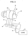
- FIG. 3 is a schematic drawing of an exemplary dual-lobed intake cam and selection mechanism in accordance with the present invention.
- FIG. 4 is a valve lift diagram showing the variation in intake cam timing by the dual-lobed cams in accordance with the present invention.
- a diesel engine has a variable compression ratio in accordance with the invention.
- a diesel engine conventionally includes a plurality of cylinders having therein reciprocable pistons connected with a crankshaft. The ends of the cylinder are closed by a cylinder head so that the cylinders and pistons define expansible combustion chambers.
- the cylinder head is provided with intake valves which control the timing and flow of intake air into the cylinders during intake strokes of the pistons.
- Exhaust valves in the cylinder head control timing and flow of exhaust products from the combustion chambers during exhaust strokes of the pistons.
- intake valves and multiple exhaust valves for each cylinder, however, any suitable number of valves provided for operation of the engine may be utilized in accordance with the invention.
- the intake and the exhaust valves are actuated by separate intake and exhaust camshafts through rocker arms.
- the intake and exhaust camshafts exclusively operate their respective intake and exhaust valves, however, both are driven by the crankshaft through a timing chain.
- FIG. 1 illustrates an end view of a first dual-lobed intake cam 10 in accordance with the present invention.
- Intake valve opening side 11 and closing side 13 are shown on opposite sides of the cam apex.
- Both cam lobes in this embodiment share a common nominal valve opening profile 15.
- the high compression cam lobe has a nominal valve closing profile 17 whereas the low compression cam lobe has a retarded valve closing profile 19.
- FIG. 2 illustrates an end view of a second dual-lobed intake cam 10' in accordance with the present invention.
- Intake valve opening side 11 and closing side 13 are shown on opposite sides of the cam apex.
- the high compression cam lobe has a retarded valve opening profile 21 and a nominal valve closing profile 17.
- the low compression cam lobe has a nominal valve opening profile 15 and a retarded valve closing profile 19.
- FIG. 3 there is shown a schematic view of a portion of the intake camshaft 26 including cam 32 including a high compression cam lobe 32A and a low compression cam lobe 32B which engage rocker arm 34 and follower 33 respectively to selectively actuate the intake valves (not shown).
- Rocker arm 34 and follower 33 are selectively coupled and decoupled by pin 35 which is actuated by pin actuation mechanism 37 connected to control 38.
- the control 38 provides pressurized oil to the pin actuation mechanism 37 as needed to displace pin 35 to couple the rocker arm 34 and follower 33 to move in unison.
- Control 38 also exhausts oil from pin actuation mechanism 37 to allow pin 35 to return to a position, such as by a return spring (not shown), whereby rocker 34 and follower 33 are decoupled to move independently.
- Rocker arm 34 is linked to an intake valve which is opened and closed in accordance with its motion.
- Follower 33 is not coupled to an intake valve and operates with lost motion unless coupled to rocker arm 34 through pin 35.
- the higher profile low compression cam lobe 32B causes actuation of the intake valve via follower 33 linked by pin 35 to rocker arm 34.
- Such cam lobe selection mechanisms are well known in the art of gasoline fueled engines.
- Other lost motion types of mechanisms are also known for engaging and disengaging rocker arms and followers to selectively operate in unison or independently.
- Control 38 comprises a conventional microprocessor-based engine or powertrain controller including CPU, ROM, RAM, I/O circuitry including A/D and D/A conversion and serial data bus communications.
- Control 38 monitors or derives a variety of parameters used in engine and powertrain controls including non exhaustive exemplary parameters such as engine coolant temperature, intake air temperature and mass flow, manifold pressure, exhaust gas constituents, engine speed, crankshaft angles and engine output torque.
- Control 38 further includes a variety of controlled actuators and control signal therefore such as solenoids and motors including for providing and exhausting pressurized oil to and from the actuation mechanism 37 to effect positional control of pin 35.
- FIG. 4 of the drawings there is illustrated a valve timing diagram.
- the lift motions of the valves are illustrated by an intake curve 42.
- the intake valve opening begins at about 16 degrees before top dead center (BTDC) and proceeds along nominal lift curve 53 to a peak at about 100 degrees after top dead center (ATDC). Thereafter, the intake valve proceeds down nominal closing curve 54 to valve closing at slightly after 220 degrees ATDC. Operation with this high compression valve timing provides a relatively high compression ratio in the engine which may approximate 15.5/1 to 20/1 depending on the design of the particular engine.
- the intake valve opening begins at about 16 degrees BTDC and proceeds along nominal lift curve 53 to a peak at about 100 degrees ATDC. Thereafter, the intake valve proceeds down retarded closing curve 52 to valve closing at about 240 degrees ATDC. Operation with this low compression valve timing provides a relatively low compression ratio in the engine which may approximate 11/1 to 15/1 depending on the design of the particular engine. With this retarded timing of the intake valve closing and this nominal intake valve opening, the intake valve closing is delayed relative to the nominal timing by about 20 degrees. Thus, the effective compression stroke is shortened by about 20 degrees from that of the high compression intake valve cam lobe of FIG. 1 . The result is that the effective compression ratio of the engine is reduced.
- the intake valve opening begins slightly before 40 degrees ATDC and proceeds along retarded lift curve 51 to a peak at about 110-130 degrees ATDC. Thereafter, the intake valve proceeds down nominal closing curve 54 to valve closing at slightly after 220 degrees ATDC. Operation with this high compression valve timing provides a relatively high compression ratio in the engine which may approximate 14/1 to 18/1 depending on the design of the particular engine. With this retarded timing of the intake valve opening and this nominal intake valve closing, the intake valve opening is delayed relative to the nominal timing until about 36 degrees after top dead center (ATDC) of the respective pistons. Thus, the temperature of the charge is increased (relative to the low compression ratio case) due to the intake throttling and the higher compression ratio. The result is that more robust combustion will be achieved during cold running operation.
- ATDC top dead center
- the intake valve opening begins at about 16 degrees BTDC and proceeds along nominal lift curve 53 to a peak at about 100 degrees ATDC. Thereafter, the intake valve proceeds down retarded closing curve 52 to valve closing at about 240 degrees ATDC. Operation with this low compression valve timing provides a relatively low compression ratio in the engine which may approximate 11/1 to 15/1 depending on the design of the particular engine. With this retarded timing of the intake valve closing and this nominal intake valve opening, the intake valve closing is delayed relative to the nominal timing by about 20 degrees. Thus, the effective compression stroke is shortened by about 20 degrees from that of the high compression intake valve cam lobe of FIG. 1 . The result is that the effective compression ratio of the engine is reduced.
- the high compression mode of operation is utilized for cold engine starting and warm-up. This is necessary because the intake air charge must be compressed to a gas temperature high enough to provide reliable and consistent compression ignition of fuel injected into the combustion chambers near their piston top dead center positions. After the engine is warmed up and the cylinder and piston walls are heated, reduction of the compression ratio to a lower range, such as 12/1 to 16/1 depending on the engine configuration, can be utilized to provide effective compression ignition to operate with reduced combustion temperatures in order to control or limit NOx emissions. Thus, during warmed-up conditions, the low compression mode of operation is utilized.
- the boost level may be increased to provide a trapped mass of the intake gas charge, including air and exhaust gases if needed, that is equivalent to the mass provided without the reduced compression ratio. Burning and expansion of the larger charge with the reduced compression ratio then results in a greater temperature reduction and a resulting greater reduction in NOx emissions.
Description
- This invention relates to a diesel engine in accordance with the preamble of claim 1, as it is disclosed in
ep 1 306 527 A1 or inJP 2002 339 768 A - It is known in the art to provide means for varying the compression ratio of a diesel engine in order to provide a relatively high compression ratio for cold starting and warm-up, where compression ignition is more difficult, and to provide reduced compression ratios for operating in other modes, particularly at high loads and speeds, to reduce peak combustion pressures and temperatures. Recently the emphasis for such arrangements is primarily to minimize emissions of nitrogen oxides (NOx) by operating at lower compression ratios where this is possible. For example,
US 2002/0177938 A1 discloses an apparatus for early intake valve closing using a cam phaser. Many devices have been proposed for compression ratio variation, including variable valve timing mechanisms and engine components such as pistons and cylinder heads with movable combustion chamber walls. In general these devices are relatively complex and add significant cost to the manufacture of an engine. - In spark ignition engines, dual-lobed cams with lobe selection mechanisms are known devices for varying valve timing, duration and lift thus changing valve timing. These devices normally provide for both advancing valve opening and retarding valve closing in order to obtain desirable performance characteristics. It is believed that dual-lobed cams with lobe selection mechanisms have not been utilized on diesel engines because the piston to cylinder head clearance is so small that altering intake and exhaust valve timing may result in contact of the pistons with the valves.
A simple and relatively low cost apparatus and method for controlling compression ratio in a diesel engine is desired. - The present invention provides a desired engine combination by the addition of dual-lobed cams with lobe selection mechanism capable of retarding the closure timing of only the intake valves of a diesel engine in order to reduce its compression ratio. A typical diesel engine has cylinders and pistons defining expansible combustion chambers into which air is admitted and compressed during compression strokes of the pistons. Compression increases the air temperature so that injected fuel is self-ignited and burns, creating power to drive a crankshaft. Intake and exhaust valves, actuated by separate crankshaft driven intake and exhaust camshafts, control timed admission of air to and discharge of exhaust products from the combustion chambers.
- In accordance with the invention, dual-lobed cams with lobe selection mechanisms are mounted in the valve train and are operable to selectively retard timing of only the intake valves relative to the crankshaft. The purpose of retarding timing of the intake valves is to retard valve closing sufficiently to shorten the effective compression strokes of the pistons and thus reduce the effective compression ratio. This occurs when the intake valves remain open past piston bottom dead center for a desired period into the normal compression stroke phase of engine operation. This reduces compression pressures in the combustion chambers so that combustion temperatures are reduced and exhaust emissions, primarily NOx, may be thus limited under conditions of warmed-up engine operation.
- Additional reductions in combustion temperatures can be achieved, in conjunction with use of dual-lobed intake cams in turbocharged or supercharged diesel engines, by increasing the intake boost pressure to maintain constant trapped air mass in the cylinder, even when intake valve closing retard is utilized. This approach allows maintaining lower combustion temperatures, thus inhibiting NOx and soot formation by preventing increases in fuel-air ratio as compression ratio is decreased.
- For cold running conditions to avoid excessive hydrocarbon and white smoke emissions from poor ignition and incomplete combustion, a dual-lobed cam can also be used to increase charge temperature by delaying intake valve opening. This increases the pumping losses which are converted into thermal energy thus raising the in-cylinder charge temperature. This increased charge temperature improves ignitability of the charge and completeness of combustion.
- These and other features and advantages of the invention will be more fully understood from the following description of certain specific embodiments of the invention taken together with the accompanying drawings.
-
FIG. 1 is a profile view of a first dual-lobed intake cam for a diesel engine to provide nominal and retarded intake valve closure for high and low compression operation, respectively; -
FIG. 2 is a profile view of a second dual-lobed intake cam for a diesel engine to provide retarded intake valve opening and nominal intake valve closure for high compression operation and nominal intake valve opening and retarded intake valve closure for low compression operation; -
FIG. 3 is a schematic drawing of an exemplary dual-lobed intake cam and selection mechanism in accordance with the present invention; and -
FIG. 4 is a valve lift diagram showing the variation in intake cam timing by the dual-lobed cams in accordance with the present invention. - A diesel engine has a variable compression ratio in accordance with the invention. A diesel engine conventionally includes a plurality of cylinders having therein reciprocable pistons connected with a crankshaft. The ends of the cylinder are closed by a cylinder head so that the cylinders and pistons define expansible combustion chambers.
- The cylinder head is provided with intake valves which control the timing and flow of intake air into the cylinders during intake strokes of the pistons. Exhaust valves in the cylinder head control timing and flow of exhaust products from the combustion chambers during exhaust strokes of the pistons. In the engine there may be multiple intake valves and multiple exhaust valves for each cylinder, however, any suitable number of valves provided for operation of the engine may be utilized in accordance with the invention.
- The intake and the exhaust valves are actuated by separate intake and exhaust camshafts through rocker arms. The intake and exhaust camshafts exclusively operate their respective intake and exhaust valves, however, both are driven by the crankshaft through a timing chain.
-
FIG. 1 illustrates an end view of a first dual-lobed intake cam 10 in accordance with the present invention. Intakevalve opening side 11 andclosing side 13 are shown on opposite sides of the cam apex. Both cam lobes in this embodiment share a common nominalvalve opening profile 15. The high compression cam lobe has a nominalvalve closing profile 17 whereas the low compression cam lobe has a retardedvalve closing profile 19. -
FIG. 2 illustrates an end view of a second dual-lobed intake cam 10' in accordance with the present invention. Intakevalve opening side 11 andclosing side 13 are shown on opposite sides of the cam apex. The high compression cam lobe has a retardedvalve opening profile 21 and a nominalvalve closing profile 17. The low compression cam lobe has a nominalvalve opening profile 15 and a retardedvalve closing profile 19. - Referring to
FIG. 3 , there is shown a schematic view of a portion of theintake camshaft 26 includingcam 32 including a highcompression cam lobe 32A and a lowcompression cam lobe 32B which engagerocker arm 34 andfollower 33 respectively to selectively actuate the intake valves (not shown). Rockerarm 34 andfollower 33 are selectively coupled and decoupled bypin 35 which is actuated bypin actuation mechanism 37 connected tocontrol 38. Throughinternal passages 40, thecontrol 38 provides pressurized oil to thepin actuation mechanism 37 as needed to displacepin 35 to couple therocker arm 34 andfollower 33 to move in unison.Control 38 also exhausts oil frompin actuation mechanism 37 to allowpin 35 to return to a position, such as by a return spring (not shown), wherebyrocker 34 andfollower 33 are decoupled to move independently.Rocker arm 34 is linked to an intake valve which is opened and closed in accordance with its motion.Follower 33 is not coupled to an intake valve and operates with lost motion unless coupled torocker arm 34 throughpin 35. The higher profile lowcompression cam lobe 32B causes actuation of the intake valve viafollower 33 linked bypin 35 torocker arm 34. Such cam lobe selection mechanisms are well known in the art of gasoline fueled engines. Other lost motion types of mechanisms are also known for engaging and disengaging rocker arms and followers to selectively operate in unison or independently. -
Control 38 comprises a conventional microprocessor-based engine or powertrain controller including CPU, ROM, RAM, I/O circuitry including A/D and D/A conversion and serial data bus communications.Control 38 monitors or derives a variety of parameters used in engine and powertrain controls including non exhaustive exemplary parameters such as engine coolant temperature, intake air temperature and mass flow, manifold pressure, exhaust gas constituents, engine speed, crankshaft angles and engine output torque.Control 38 further includes a variety of controlled actuators and control signal therefore such as solenoids and motors including for providing and exhausting pressurized oil to and from theactuation mechanism 37 to effect positional control ofpin 35. - Referring now to
FIG. 4 of the drawings, there is illustrated a valve timing diagram. The lift motions of the valves are illustrated by anintake curve 42. As illustrated for high compression operation in accordance with the first dual-lobed cam 10 inFIG. 1 , the intake valve opening begins at about 16 degrees before top dead center (BTDC) and proceeds along nominal lift curve 53 to a peak at about 100 degrees after top dead center (ATDC). Thereafter, the intake valve proceeds downnominal closing curve 54 to valve closing at slightly after 220 degrees ATDC. Operation with this high compression valve timing provides a relatively high compression ratio in the engine which may approximate 15.5/1 to 20/1 depending on the design of the particular engine. - For low compression operation in accordance with the first dual-
lobed cam 10 inFIG. 1 , the intake valve opening begins at about 16 degrees BTDC and proceeds along nominal lift curve 53 to a peak at about 100 degrees ATDC. Thereafter, the intake valve proceeds downretarded closing curve 52 to valve closing at about 240 degrees ATDC. Operation with this low compression valve timing provides a relatively low compression ratio in the engine which may approximate 11/1 to 15/1 depending on the design of the particular engine. With this retarded timing of the intake valve closing and this nominal intake valve opening, the intake valve closing is delayed relative to the nominal timing by about 20 degrees. Thus, the effective compression stroke is shortened by about 20 degrees from that of the high compression intake valve cam lobe ofFIG. 1 . The result is that the effective compression ratio of the engine is reduced. - With continued reference to
FIG. 4 of the drawings and for high compression operation in accordance with the second dual-lobed cam 10' inFIG. 2 , the intake valve opening begins slightly before 40 degrees ATDC and proceeds alongretarded lift curve 51 to a peak at about 110-130 degrees ATDC. Thereafter, the intake valve proceeds downnominal closing curve 54 to valve closing at slightly after 220 degrees ATDC. Operation with this high compression valve timing provides a relatively high compression ratio in the engine which may approximate 14/1 to 18/1 depending on the design of the particular engine. With this retarded timing of the intake valve opening and this nominal intake valve closing, the intake valve opening is delayed relative to the nominal timing until about 36 degrees after top dead center (ATDC) of the respective pistons. Thus, the temperature of the charge is increased (relative to the low compression ratio case) due to the intake throttling and the higher compression ratio. The result is that more robust combustion will be achieved during cold running operation. - For low compression operation in accordance with the second dual-lobed cam 10' in
FIG. 2 , the intake valve opening begins at about 16 degrees BTDC and proceeds along nominal lift curve 53 to a peak at about 100 degrees ATDC. Thereafter, the intake valve proceeds downretarded closing curve 52 to valve closing at about 240 degrees ATDC. Operation with this low compression valve timing provides a relatively low compression ratio in the engine which may approximate 11/1 to 15/1 depending on the design of the particular engine. With this retarded timing of the intake valve closing and this nominal intake valve opening, the intake valve closing is delayed relative to the nominal timing by about 20 degrees. Thus, the effective compression stroke is shortened by about 20 degrees from that of the high compression intake valve cam lobe ofFIG. 1 . The result is that the effective compression ratio of the engine is reduced. - In operation, the high compression mode of operation is utilized for cold engine starting and warm-up. This is necessary because the intake air charge must be compressed to a gas temperature high enough to provide reliable and consistent compression ignition of fuel injected into the combustion chambers near their piston top dead center positions. After the engine is warmed up and the cylinder and piston walls are heated, reduction of the compression ratio to a lower range, such as 12/1 to 16/1 depending on the engine configuration, can be utilized to provide effective compression ignition to operate with reduced combustion temperatures in order to control or limit NOx emissions. Thus, during warmed-up conditions, the low compression mode of operation is utilized.
- While this will provide reduced combustion temperatures resulting in a reduction of NOx emissions, the effect is limited by fuel heating of the smaller gas charge. With a turbocharged or supercharged engine, the boost level may be increased to provide a trapped mass of the intake gas charge, including air and exhaust gases if needed, that is equivalent to the mass provided without the reduced compression ratio. Burning and expansion of the larger charge with the reduced compression ratio then results in a greater temperature reduction and a resulting greater reduction in NOx emissions.
- When the engine is again operated at light loads or during starting and warm-up, the
pin 35 is returned to its retracted position, the high compression cam lobe is again effective, and the compression ratio is again increased so that dependable compression ignition of the intake air fuel charge is obtained. - In order to use a dual-lobed intake cam in the manner outlined for reducing the effective compression ratio and resulting compression temperatures of a diesel engine, the cam lobes must not advance the intake valve opening. The variations in valve timing for which dual-lobed cams are utilized in spark ignition engines are not generally usable in diesel engines because the intake valve timing cannot be advanced without the pistons contacting the valves due to the low piston to head clearance.
- Thus, the application of dual-lobed cams to a diesel engine is not known to have previously been considered practical. However, the use in the present invention, where only retarding of the intake valves from their nominal timing is utilized, provides a simple and low cost method of controlling combustion temperatures and controlling NOx emissions in warmed-up operation of a diesel engine.
Claims (9)
- Diesel engine having cylinders and pistons defining expansible combustion chambers into which combustion supporting gas is compressed during compression strokes of the pistons for compression ignition and burning of injected fuel to drive a crankshaft, intake and exhaust valves actuated by crankshaft driven intake and exhaust camshafts for controlling the timed admission of air to and the discharge of exhaust from the combustion chambers, and for each cylinder the improvement being c h a r a c t e r i z e d by:an intake cam (10, 10', 32) having first and second cam lobes (32A, 32B) of different profiles on the intake camshaft (26) wherein the first cam lobe (32A) has a first intake valve closing profile (17) and the second cam lobe (32B) has a second intake valve closing profile (19) that is retarded relative to the first intake valve closing profile (17); and,a selection mechanism (37) for selectively coupling one of the two cam lobes (32A, 32B) to respective intake valves, whereby the first intake valve closing profile (17) effects a relatively high effective compression ratio and high combustion temperatures and the second intake valve closing profile (19) effects a relatively low effective compression ratio and low combustion temperatures.
- The diesel engine as claimed in claim 1 wherein the first and second cam lobes (32A, 32B) have substantially identical intake valve opening profiles (15).
- The diesel engine as claimed in claim 1 wherein the first cam lobe (32A) has a first intake valve opening profile (21) and the second cam lobe (32B) has a second intake valve opening profile (15), said first intake valve opening profile (21) being retarded relative to the second intake valve opening profile (15), whereby the first intake valve opening profile (21) effects throttling of admitted air and high combustion temperatures relative to the second intake valve opening profile.
- The diesel engine as claimed in claim 1 wherein the second intake valve closing profile (19) is retarded relative to the first intake valve closing profile (17) by about 5 to about 35 crankshaft degrees.
- The diesel engine as claimed in claim 3 wherein the first intake valve opening profile (21) is retarded relative to the second intake valve opening profile (15) by about 20 to about 65 crankshaft degrees.
- The diesel engine as claimed in claim 3 wherein the second intake valve closing profile (19) is retarded relative to the first intake valve closing profile (17) by about 5 to about 35 crankshaft degrees and the first intake valve opening profile (21) is retarded relative to the second intake valve opening profile (15) by about 20 to about 65 crankshaft degrees.
- The diesel engine as claimed in claim 1 wherein the second intake valve closing profile (19) is retarded relative to the first intake valve closing profile (17) by about 20 crankshaft degrees.
- The diesel engine as claimed in claim 3 wherein the first intake valve opening profile (21) is retarded relative to the second intake valve opening profile (15) by about 56 crankshaft degrees.
- The diesel engine as claimed in claim 3 wherein the second intake valve closing profile (19) is retarded relative to the first intake valve closing profile (17) by about 20 crankshaft degrees and the first intake valve opening profile (21) is retarded relative to the second intake valve opening profile (15) by about 56 crankshaft degrees.
Applications Claiming Priority (2)
| Application Number | Priority Date | Filing Date | Title |
|---|---|---|---|
| US739462 | 2003-12-18 | ||
| US10/739,462 US7036483B2 (en) | 2003-12-18 | 2003-12-18 | Diesel engine with dual-lobed intake cam for compression ratio control |
Publications (3)
| Publication Number | Publication Date |
|---|---|
| EP1550794A2 EP1550794A2 (en) | 2005-07-06 |
| EP1550794A3 EP1550794A3 (en) | 2009-12-30 |
| EP1550794B1 true EP1550794B1 (en) | 2013-04-17 |
Family
ID=34574725
Family Applications (1)
| Application Number | Title | Priority Date | Filing Date |
|---|---|---|---|
| EP04029600.6A Active EP1550794B1 (en) | 2003-12-18 | 2004-12-14 | Diesel engine with dual-lobed intake cam for compression ratio control |
Country Status (2)
| Country | Link |
|---|---|
| US (1) | US7036483B2 (en) |
| EP (1) | EP1550794B1 (en) |
Families Citing this family (8)
| Publication number | Priority date | Publication date | Assignee | Title |
|---|---|---|---|---|
| US7762225B2 (en) * | 2003-10-25 | 2010-07-27 | Audi Ag | Valve train of an internal combustion engine comprising at least one camshaft |
| US7434640B2 (en) * | 2005-07-27 | 2008-10-14 | Eaton Corporation | Method for reducing torque required to crank engine in hybrid vehicle |
| US7882631B2 (en) * | 2005-10-13 | 2011-02-08 | Anthony Nicholas Zurn | Methods for controlling valves of an internal combustion engine, devices for controlling the valves, and engines employing the methods |
| US7882811B2 (en) * | 2006-10-12 | 2011-02-08 | Anthony Nicholas Zurn | Methods for controlling valves of an internal combustion engine, devices for controlling the valves, and engines employing the methods |
| GB2443419A (en) * | 2006-11-06 | 2008-05-07 | Mechadyne Plc | Internal combustion engine valve mechanism allowing variable phase compression braking |
| US8191519B2 (en) * | 2009-04-24 | 2012-06-05 | GM Global Technology Operations LLC | Method and apparatus for operating an internal combustion engine |
| WO2017140351A1 (en) | 2016-02-16 | 2017-08-24 | Volvo Truck Corporation | A device for controlling at least one valve in an internal combustion engine |
| CN113202628A (en) * | 2021-06-02 | 2021-08-03 | 北京理工大学 | Two-stage low-compression-cycle implementation method, device and detection method |
Citations (2)
| Publication number | Priority date | Publication date | Assignee | Title |
|---|---|---|---|---|
| US5931124A (en) * | 1996-06-18 | 1999-08-03 | Dr. Ing. H.C.F. Porsche Ag | Valve timing for internal-combustion engines |
| JP2002339768A (en) * | 2001-05-14 | 2002-11-27 | Denso Corp | Control device for diesel engine |
Family Cites Families (17)
| Publication number | Priority date | Publication date | Assignee | Title |
|---|---|---|---|---|
| US4399784A (en) * | 1981-02-10 | 1983-08-23 | Foley James E | Internal combustion engine |
| US4587934A (en) * | 1983-05-16 | 1986-05-13 | Moores Keith J | Variable-timing valve actuating mechanism |
| JPS62203913A (en) * | 1986-02-28 | 1987-09-08 | Fuji Heavy Ind Ltd | Tappet valve device for automobile engine |
| JPH086568B2 (en) * | 1989-04-13 | 1996-01-24 | 日産自動車株式会社 | Engine valve operation control device |
| US5253546A (en) * | 1990-05-29 | 1993-10-19 | Clemson University | Variable valve actuating apparatus |
| US5129407A (en) * | 1991-06-10 | 1992-07-14 | J. D. Phillips Corporation | Variable camshaft |
| US5287840A (en) * | 1992-07-30 | 1994-02-22 | General Electric Canada Inc. | Cam sections for a "V"-type diesel engine |
| US5253622A (en) * | 1993-02-17 | 1993-10-19 | Bornstein Motor Company, Inc. | Cam phase change mechanism |
| DE19638331A1 (en) * | 1995-09-28 | 1997-04-03 | Volkswagen Ag | Cam arrangement for internal combustion engine |
| DE19702389B4 (en) * | 1997-01-24 | 2004-05-27 | Audi Ag | Valve train for an internal combustion engine |
| AUPP330998A0 (en) * | 1998-05-04 | 1998-05-28 | Bentley, Paul Joseph | Variable duration, overlap and cam timing |
| US6170449B1 (en) * | 1998-09-30 | 2001-01-09 | Yamaha Hatsudoki Kabushiki Kaisha | Valve operating system for engine |
| JP3447601B2 (en) * | 1999-02-05 | 2003-09-16 | 本田技研工業株式会社 | Valve operating control device for internal combustion engine |
| WO2001077502A1 (en) * | 2000-04-10 | 2001-10-18 | Honda Giken Kogyo Kabushiki Kaisha | Valve gear of internal combustion engine |
| US6600989B2 (en) * | 2001-05-24 | 2003-07-29 | Delphi Technologies, Inc. | Apparatus and method for early intake valve closing |
| DE50113447D1 (en) * | 2001-10-25 | 2008-02-14 | Ford Global Tech Llc | Diesel engine with variable compression ratio |
| US6705259B1 (en) * | 2002-12-10 | 2004-03-16 | Delphi Technologies, Inc. | 3-step cam-profile-switching roller finger follower |
-
2003
- 2003-12-18 US US10/739,462 patent/US7036483B2/en not_active Expired - Lifetime
-
2004
- 2004-12-14 EP EP04029600.6A patent/EP1550794B1/en active Active
Patent Citations (2)
| Publication number | Priority date | Publication date | Assignee | Title |
|---|---|---|---|---|
| US5931124A (en) * | 1996-06-18 | 1999-08-03 | Dr. Ing. H.C.F. Porsche Ag | Valve timing for internal-combustion engines |
| JP2002339768A (en) * | 2001-05-14 | 2002-11-27 | Denso Corp | Control device for diesel engine |
Also Published As
| Publication number | Publication date |
|---|---|
| EP1550794A3 (en) | 2009-12-30 |
| EP1550794A2 (en) | 2005-07-06 |
| US20050132982A1 (en) | 2005-06-23 |
| US7036483B2 (en) | 2006-05-02 |
Similar Documents
| Publication | Publication Date | Title |
|---|---|---|
| US7308872B2 (en) | Method and apparatus for optimized combustion in an internal combustion engine utilizing homogeneous charge compression ignition and variable valve actuation | |
| US6321731B1 (en) | Engine control strategy using dual equal cam phasing combined with exhaust gas recirculation | |
| US6082342A (en) | Process for controlling self-ignition in a 4-stroke engine | |
| US7962276B2 (en) | Combustion chamber deactivation system | |
| US20080215228A1 (en) | Variable Valve Drive For a Reciprocating Internal Combustion Engine | |
| US9765658B2 (en) | Valve train system for an internal combustion engine | |
| EP1770269A2 (en) | Multistage fuel-injection internal combustion engine | |
| JP2007113485A (en) | Method and device for controlling internal combustion engine | |
| GB2387620A (en) | Cylinder deactivation in a variable displacement i.c. engine by intake cam phasing and exhaust valve deactivation | |
| US8479509B2 (en) | Internal combustion engine | |
| WO2008065856A1 (en) | Premixed compression ignition type engine and method of controlling the same | |
| US20120283932A1 (en) | Two-stroke internal combustion engine with variable compression ratio and an exhaust port shutter and a method of operating such an engine | |
| US7258100B2 (en) | Internal combustion engine control | |
| US6830020B1 (en) | Diesel engine with intake cam phaser for compression ratio control | |
| US4050420A (en) | Constant pressure-temperature delayed combustion high compression ratio engine and method | |
| US6918384B2 (en) | Diesel engine with cam phasers for in-cylinder temperature control | |
| WO2004076831A2 (en) | Controlled auto-ignition engine | |
| EP1550794B1 (en) | Diesel engine with dual-lobed intake cam for compression ratio control | |
| US7347179B2 (en) | Method for operating an internal combustion engine | |
| US20030140877A1 (en) | Four-stroke gasoline engine with direct injection and method for valve control | |
| US20080134999A1 (en) | Internal combustion engine, a method in such an engine, and a method for producing such an engine | |
| US6779498B2 (en) | Internal combustion engine operating on spark-ignitable fuel | |
| JP4139772B2 (en) | Internal combustion engine that can be operated in controlled auto-ignition mode | |
| EP1472445B1 (en) | Dual mode engine with controlled auto-ignition | |
| US9404428B1 (en) | Variable-expansion-ratio engine |
Legal Events
| Date | Code | Title | Description |
|---|---|---|---|
| PUAI | Public reference made under article 153(3) epc to a published international application that has entered the european phase |
Free format text: ORIGINAL CODE: 0009012 |
|
| AK | Designated contracting states |
Kind code of ref document: A2 Designated state(s): AT BE BG CH CY CZ DE DK EE ES FI FR GB GR HU IE IS IT LI LT LU MC NL PL PT RO SE SI SK TR |
|
| AX | Request for extension of the european patent |
Extension state: AL BA HR LV MK YU |
|
| PUAL | Search report despatched |
Free format text: ORIGINAL CODE: 0009013 |
|
| AK | Designated contracting states |
Kind code of ref document: A3 Designated state(s): AT BE BG CH CY CZ DE DK EE ES FI FR GB GR HU IE IS IT LI LT LU MC NL PL PT RO SE SI SK TR |
|
| AX | Request for extension of the european patent |
Extension state: AL BA HR LV MK YU |
|
| RIC1 | Information provided on ipc code assigned before grant |
Ipc: F01L 1/344 20060101ALI20091120BHEP Ipc: F01L 13/00 20060101AFI20050511BHEP |
|
| 17P | Request for examination filed |
Effective date: 20100630 |
|
| AKX | Designation fees paid |
Designated state(s): DE FR GB |
|
| 17Q | First examination report despatched |
Effective date: 20100824 |
|
| RAP1 | Party data changed (applicant data changed or rights of an application transferred) |
Owner name: GM GLOBAL TECHNOLOGY OPERATIONS, INC. |
|
| RAP1 | Party data changed (applicant data changed or rights of an application transferred) |
Owner name: GM GLOBAL TECHNOLOGY OPERATIONS, INC. |
|
| RAP1 | Party data changed (applicant data changed or rights of an application transferred) |
Owner name: GM GLOBAL TECHNOLOGY OPERATIONS LLC |
|
| GRAP | Despatch of communication of intention to grant a patent |
Free format text: ORIGINAL CODE: EPIDOSNIGR1 |
|
| GRAS | Grant fee paid |
Free format text: ORIGINAL CODE: EPIDOSNIGR3 |
|
| GRAA | (expected) grant |
Free format text: ORIGINAL CODE: 0009210 |
|
| AK | Designated contracting states |
Kind code of ref document: B1 Designated state(s): DE FR GB |
|
| REG | Reference to a national code |
Ref country code: GB Ref legal event code: FG4D |
|
| REG | Reference to a national code |
Ref country code: DE Ref legal event code: R096 Ref document number: 602004041758 Country of ref document: DE Effective date: 20130613 |
|
| PLBE | No opposition filed within time limit |
Free format text: ORIGINAL CODE: 0009261 |
|
| STAA | Information on the status of an ep patent application or granted ep patent |
Free format text: STATUS: NO OPPOSITION FILED WITHIN TIME LIMIT |
|
| 26N | No opposition filed |
Effective date: 20140120 |
|
| REG | Reference to a national code |
Ref country code: DE Ref legal event code: R097 Ref document number: 602004041758 Country of ref document: DE Effective date: 20140120 |
|
| GBPC | Gb: european patent ceased through non-payment of renewal fee |
Effective date: 20131214 |
|
| REG | Reference to a national code |
Ref country code: FR Ref legal event code: ST Effective date: 20140829 |
|
| PG25 | Lapsed in a contracting state [announced via postgrant information from national office to epo] |
Ref country code: FR Free format text: LAPSE BECAUSE OF NON-PAYMENT OF DUE FEES Effective date: 20131231 Ref country code: GB Free format text: LAPSE BECAUSE OF NON-PAYMENT OF DUE FEES Effective date: 20131214 |
|
| PGFP | Annual fee paid to national office [announced via postgrant information from national office to epo] |
Ref country code: DE Payment date: 20231121 Year of fee payment: 20 |