EP2495163A1 - Ship resistance-reduction device - Google Patents
Ship resistance-reduction device Download PDFInfo
- Publication number
- EP2495163A1 EP2495163A1 EP10826471A EP10826471A EP2495163A1 EP 2495163 A1 EP2495163 A1 EP 2495163A1 EP 10826471 A EP10826471 A EP 10826471A EP 10826471 A EP10826471 A EP 10826471A EP 2495163 A1 EP2495163 A1 EP 2495163A1
- Authority
- EP
- European Patent Office
- Prior art keywords
- gas room
- scattering member
- opening
- width direction
- frictional resistance
- Prior art date
- Legal status (The legal status is an assumption and is not a legal conclusion. Google has not performed a legal analysis and makes no representation as to the accuracy of the status listed.)
- Granted
Links
Images





Classifications
-
- B—PERFORMING OPERATIONS; TRANSPORTING
- B63—SHIPS OR OTHER WATERBORNE VESSELS; RELATED EQUIPMENT
- B63B—SHIPS OR OTHER WATERBORNE VESSELS; EQUIPMENT FOR SHIPPING
- B63B1/00—Hydrodynamic or hydrostatic features of hulls or of hydrofoils
- B63B1/32—Other means for varying the inherent hydrodynamic characteristics of hulls
- B63B1/34—Other means for varying the inherent hydrodynamic characteristics of hulls by reducing surface friction
- B63B1/38—Other means for varying the inherent hydrodynamic characteristics of hulls by reducing surface friction using air bubbles or air layers gas filled volumes
-
- B—PERFORMING OPERATIONS; TRANSPORTING
- B63—SHIPS OR OTHER WATERBORNE VESSELS; RELATED EQUIPMENT
- B63B—SHIPS OR OTHER WATERBORNE VESSELS; EQUIPMENT FOR SHIPPING
- B63B1/00—Hydrodynamic or hydrostatic features of hulls or of hydrofoils
- B63B1/32—Other means for varying the inherent hydrodynamic characteristics of hulls
- B63B1/34—Other means for varying the inherent hydrodynamic characteristics of hulls by reducing surface friction
- B63B1/38—Other means for varying the inherent hydrodynamic characteristics of hulls by reducing surface friction using air bubbles or air layers gas filled volumes
- B63B2001/387—Other means for varying the inherent hydrodynamic characteristics of hulls by reducing surface friction using air bubbles or air layers gas filled volumes using means for producing a film of air or air bubbles over at least a significant portion of the hull surface
-
- Y—GENERAL TAGGING OF NEW TECHNOLOGICAL DEVELOPMENTS; GENERAL TAGGING OF CROSS-SECTIONAL TECHNOLOGIES SPANNING OVER SEVERAL SECTIONS OF THE IPC; TECHNICAL SUBJECTS COVERED BY FORMER USPC CROSS-REFERENCE ART COLLECTIONS [XRACs] AND DIGESTS
- Y02—TECHNOLOGIES OR APPLICATIONS FOR MITIGATION OR ADAPTATION AGAINST CLIMATE CHANGE
- Y02T—CLIMATE CHANGE MITIGATION TECHNOLOGIES RELATED TO TRANSPORTATION
- Y02T70/00—Maritime or waterways transport
- Y02T70/10—Measures concerning design or construction of watercraft hulls
Definitions
- the present invention is related to a frictional resistance reducing device which reduces frictional resistance of a hull through air blowing.
- a technique which reduces frictional resistance of a hull by covering the bottom surface of a ship with an air bubble flow at the time of navigation.
- a gas room 2 is provided on the bow side in a bottom section 1 of a ship.
- the gas room 2 is formed in the width direction.
- the gas room 2 is divided into three gas rooms 2a in the width direction of the ship bottom section 1 by partitions 2b. Parts of the outer plate of the ship bottom corresponding to the gas rooms 2a are cut to form bottom openings 1a with no bottom plate.
- Each gas room 2a is connected with a compressor 4 through the gas supply pipe 3.
- a baffle plate 6 is provided apart below from a connection opening of the gas supply pipe 3 in the top wall to receive a gaseous flow.
- a pair of gas holding boards 5 is provided from a bow section toward a stern section along the both sides of the ship bottom.
- the baffle plate 6 receives a gas blown from the gas supply pipe 3 into the gas room 2a, the gas filling the gas room 2a is blown in an almost uniform condition from the bottom opening 1a into the water. In this way, it is possible to generate the air bubble flow which efficiently flows to the backward side along the ship bottom surface. Moreover, the outward flow of the air bubble flow into the hull sides is prevented by the gas holding boards 5. In this way, the hull frictional resistance is reduced.
- Patent Literature 1 JP 2008-143345A
- the subject matter of the present invention is to provide a frictional resistance reducing device for a ship, for which it is not necessary to provide many air supply pipes in a hull.
- the ship frictional resistance reducing device is provided with a gas room provided in a hull to cross a longitudinal frame and to extend into the width direction, a scattering member arranged in the gas room to cross the longitudinal frame and to extend into the width direction, and an air supply pipe connected with the gas room. Air blown into the gas room from the air supply pipe hits the scattering member and is scattered into the width direction. Then, the air is blown into water from an air blowing hole.
- a first opening is provided in a portion of the gas room on a port side from the longitudinal frame to connect an inside of the hull and the gas room.
- a second opening is provided in another portion of the gas room on a starboard side from the longitudinal frame to connect the inside of the hull and the gas room.
- a first lid is attached to the first opening.
- a second lid is attached to the second opening.
- a first part of the scattering member which is a part of the scattering member on the port side from the longitudinal frame and a second part of the scattering member which is a part of the scattering member on the starboard side from the longitudinal frame can be separated from the scattering member.
- the scattering member first part has such a size that the scattering member first part is possible to pass through the first opening.
- the scattering member second part is such a size that the scattering member second part is possible to pass through the second opening.
- the first opening and the second opening are formed in an upper portion of the gas room.
- the air supply pipe is connected with the first lid or the second lid.
- the scattering member first part is attached to the first lid, and the scattering member second part is attached to the second lid.
- the first opening and the second opening are formed in a side portion in a longitudinal direction of the gas room.
- the side portion in the longitudinal direction is provided on a bow side of or a stern side of the gas room.
- the air supply pipe is connected with on the upper portion of the gas room.
- a bow side slit hole is arranged on the bow side of the scattering member to extend into the width direction.
- the stern side slit hole is arranged on the stern side of the scattering member to extend into the width direction. Air blown into the gas room from the air supply pipe passes through the bow side slit hole or the stern side slit hole and is blown into water from the air blowing hole.
- the frictional resistance reducing device of the ship for which it is not necessary to provide the many air supply pipes in the hull.
- a ship according to a first embodiment of the present invention is provided with a hull 10 and a frictional resistance reducing device 20.
- the hull 10 is provided with a bow 11, a stern 12, and a bottom in a ship 13.
- the propeller 14 and a rudder 15 are provided for the stern 12.
- the frictional resistance reducing device 20 is provided with an air feeder 21, an air supply pipe 22 and a gas room 30.
- the aerial feeder 21 is a compressor or a blower.
- the air feeder 21 and the gas room 30 are connected through the air supply pipe 22.
- the gas room 30 is provided on the side of bow 11 of the bottom of the ship 13.
- a plurality of air blowing holes 34a are formed in the gas room 30 to be opened in the bottom of the ship 13.
- the frictional resistance reducing device 20 blows air from the air blowing holes 34a into water when the ship 13 navigate.
- an air bubble flow is formed along the bottom of the ship 13 to reduce the frictional resistance of the hull 10.
- the hull 10 is provided with longitudinal frames 17 and 18.
- the longitudinal frames 17 and 18 and the longitudinal frame 16 to be described later are partitions which divide a space of the hull 10 into a width direction Y of the hull 10 (a direction from the port side to the starboard side).
- the gas room 30 is provided in the hull 10 to cross the longitudinal frame 17 (to pass through the longitudinal frame 17) and to extend to the width direction Y.
- the frictional resistance reducing device 20 is provided with a scattering member 40 which is arranged in the gas room 30.
- the scattering member 40 crosses the longitudinal frame 17 and extends the width direction Y. Therefore, the longitudinal directions of the gas room 30 and the scattering member 40 are parallel to the width direction Y. It should be noted that X in FIG.
- the air supply pipe 22 is connected with the gas room 30 from an upper side. A part of the air supply pipe 22 which is connected with the gas room 30 extends into the upper and lower directions.
- the gas room 30 will be described.
- the hull 10 is further provided with the longitudinal frame 16.
- the longitudinal frame 16 is arranged on the port side of the longitudinal frame 17.
- the longitudinal frame 18 is arranged on the starboard side of the longitudinal frame 17.
- the gas room 30 is provided with an upper member 31, a longitudinal side member 32 on the side of bow 11, a longitudinal side member 33 on the side of stern 12, and lids 35 and 36.
- An opening 31a is formed in a part of the upper member 31 on the port side from the longitudinal frame 17.
- An opening 31b is formed in a part of the upper member 31 on the starboard side from the longitudinal frame 17.
- the openings 31a and 31b connect the internal space of the gas room 30 and the internal space of the hull 10.
- the lid 35 is attached to the opening 31a by bolts 70.
- the lid 36 is attached to the opening 31b by bolts 70. Therefore, it is possible to remove the lids 35 and 36.
- the air supply pipe 22 is connected with the lid 35.
- the gas room 30 is provided with a bottom member 34 in which the plurality of air blowing holes 34a are formed.
- the bottom member 34 is formed as the bottom of the ship 13.
- the plurality of air blowing holes 34a are arranged in the width direction Y.
- the longitudinal frame 16 forms a port side member on the port side of the gas room 30.
- the longitudinal frame 18 forms a starboard side member on the starboard side of the gas room 30.
- the scattering member 40 has a block structure which is provided with a first part 41, a second part 42 and a middle part 43.
- the first part 41 forms a part of the scattering member 40 on the port side from the longitudinal frame 17.
- the second part 42 forms a part of the scattering member 40 on the starboard side from the longitudinal frame 17.
- the middle part 43 forms a part of the scattering member 40 between the first part 41 and second part 42.
- the first part 41 has a size enough to pass through the opening 31a.
- the first part 41 is attached to the lid 35 through supporting members 51.
- the second part 42 has a size enough to pass through the opening 31b.
- the second part 42 is attached to the lid 36 through supporting members 52.
- the middle part 43 is supported by the longitudinal frame 17 through a supporting member 53.
- the first part 41 and the second part 42 can be separated from the scattering member 40.
- a connection port of the air supply pipe 22 and the lid 35 is arranged straightly above the scattering member 40 (the first part 41).
- the plurality of air blowing holes 34a are arranged straightly below the scattering member 40.
- a slit hole 61 is formed between the scattering member 40 and the longitudinal side member 32 to extend in the width direction Y.
- a slit hole 62 is formed between the scattering member 40 and the longitudinal side member 33 to extend in the width direction Y.
- the slit hole 61 is arranged on the side of bow 11 of the scattering member 40.
- the slit hole 62 is arranged on the side of the stern 12 of the scattering member 40.
- the air feeder 21 supplies air into the gas room 30 through the air supply pipe 22.
- the air is blown from the air supply pipe 22 into the gas room 30 as a flow in a downward direction for the scattering member 40 (the first part 41).
- the air blown into the gas room 30 from the air supply pipe 22 hits the scattering member 40 and scatters into the width direction Y, and moreover after passing the slit hole 61 or the slit hole 62, is blown from the air blowing holes 34a into water. Therefore, an air bubble flow, which is uniform in the width direction Y, is formed along the bottom of the ship 13.
- the air bubble flow which is wide in the width direction Y can be formed by the single gas room 30 because the gas room 30 cross the longitudinal frame 17 to extend in the width direction Y. Therefore, the number of gas rooms 30 which are necessary to form the air bubble flow which covers the whole width of the bottom of the ship 13 in the width direction Y may be few, and the number of air supply pipes 22 which are provided every gas room 30 may be few. According to the present embodiment, it is not necessary to provide the many air supply pipes in the hull 10 where the space is limited.
- the opening 31a or 31b is provided between adjacent two of the longitudinal frames 16 to 18. It is possible to separate the first part 41 and the second part 42 from the scattering member 40 and to take them out of the gas room 30 (in the hull 10) through the openings 31a and 31b. Therefore, the cleaning to remove marine organisms such as barnacles which are adhered to the gas room 30 and the scattering member 40 is easy at the time of the docking. Therefore, the frictional resistance reducing device 20 according to the present embodiment is superior in the maintenance.
- the lid 35 and the first part 41 are coupled by the supporting member 51, and the lid 36 and the second part 42 are coupled by the supporting member 52, the first part 41 is taken out from the gas room 30 at the same time as removing the lid 35, and the second part 42 is taken out from the gas room 30 at the same time as removing the lid 36. Therefore, works for the maintenance can be little.
- the frictional resistance reducing device 20 according to the first modification is same as the frictional resistance reducing device 20 according to the first embodiment, excluding the following description.
- the first part 41 of the scattering member 40 is not attached to the lid 35 and the second part 42 of the scattering member 40 is not attached to the lid 36.
- a supporting members 54 is provided for as the longitudinal frame 16 (longitudinal side member of the gas room 30) on the port side and a supporting member 55 is provided for the longitudinal frame 18 (longitudinal side member of the gas room 30) on the starboard side.
- the first part 41 is attached to the supporting member 54 and the middle part 43 by bolts 70
- the second part 42 is attached to the supporting member 55 and the middle part 43 by bolts 70. Therefore, the first part 41 and the second part 42 can be detachable.
- the first part 41 is taken out of the gas room 30 (in the hull 10) through the openings 31a after removing the lid 35.
- the second part 42 is taken out of the gas room 30 (in the hull 10) through the opening 31b after removing the lid 36.
- the frictional resistance reducing device 20 according to the second modification is same as the above frictional resistance reducing device 20 according to the first embodiment, excluding the following explanation.
- the first part 41 of the scattering member 40 is not attached to the lid 35 and the second part 42 of the scattering member 40 is not attached to the lid 36.
- Supporting members 56 are provided for a part of the bottom 34 on the port side from the longitudinal frame 17 and supporting members 57 are provided for a part of the bottom 34 on the starboard side from the longitudinal frame 17.
- the first part 41 is attached to the supporting members 56 by bolts 70 and the second part 42 is attached to the supporting members 57 by bolts 70. Therefore, the first part 41 and the second part 42 are detachable.
- the first part 41 is taken out of the gas room 30 (in the hull 10) through the openings 31a after removing the lid 35.
- the second part 42 is taken out of the gas room 30 (in the hull 10) through the opening 31b after removing the lid 36.
- air supply pipe 22 may be connected with the lid 36 in the first embodiment, and the first modification and the second modification of the present embodiment.
- the frictional resistance reducing device 20 according to the second embodiment of the present invention will be described.
- the frictional resistance reducing device 20 according to the present embodiment is same as the frictional resistance reducing device 20 according to the first embodiment, excluding the following description.
- the gas room 30 is provided with lids 37 and 38. An opening is not provided for the upper member 31 of the gas room 30 and any lid attached to the opening is not provided.
- the air supply pipe 22 is connected with a part of the upper member 31 on the port side from the longitudinal frame 17.
- An opening 33a is formed in a part of the longitudinal side member 33 on the port side from the longitudinal frame 17.
- An opening 33b is formed in a part of the longitudinal side member 33 on the starboard side from the longitudinal frame 17.
- the openings 33a and 33b connect the internal space of the gas room 30 and the internal space of the hull 10, respectively.
- the lid 37 is attached to the opening 33a by bolts 70.
- the lid 38 is attached to the opening 33b by bolts 70. Therefore, the lids 37 and 38 are detachable.
- the first part 41 of the scattering member 40 has a size enough to pass through the opening 33a and the second part 42 of the scattering member 40 has a size enough to pass though the opening 33b.
- Supporting members 58 are provided for a part of the upper member 31 on the port side from the longitudinal frame 17 and supporting members 59 are provided for a part of the upper member 31 on the starboard side from the longitudinal frame 17.
- the first part 41 is attached to the supporting member 58 by bolts 70 and the second part 42 is attached to the supporting member 59 by bolts 70. Therefore, the first part 41 and the second part 42 are detachable.
- FIG. 8D shows an attachment structure of the second part 42 to the upper member 31.
- the first part 41 is attached to the upper member 31, like the second part 42.
- the gas room 30 crosses the longitudinal frame 17 and extends to the width direction Y, the air bubble flow wide in the width direction Y can be formed by the single gas room 30. Therefore, the number of gas rooms 30 which are necessary to form the air bubble flow which covers the whole width of the bottom of the ship 13 in the width direction Y may be few.
- the number of air supply pipes 22 which are provided for every gas room 30 may be few. According to the present embodiment, it is not necessary to arrange many air supply pipes in the hull 10 with a limited space.
- the opening 33a or 33b of the gas room 30 is provided between adjacent two of the longitudinal frames 16 to 18. It is possible to separate the first part 41 and the second part 42 from the scattering member 40 and to take them out of the gas room 30 (in the hull 10) through the openings 33a and 33b. Therefore, the cleaning is easy to remove the marine organisms such as barnacle adhered to the gas room 30 and the scattering member 40 at the time of the docking. Therefore, the frictional resistance reducing device 20 according to the present embodiment is superior in the maintenance.
- the air supply pipe 22 is connected with a portion of the gas room 30 other than the lids 37 and 38, the removal of the lids 37 and 38 is easy.
- the first part 41 may be supported by the longitudinal side member 16 and the middle part 43 in the gas room 30.
- the second part 42 may be supported by the longitudinal side member 18 and the middle part 43 in the gas room 30.
- the first part 41 and the second part 42 may be supported to the bottom 34.
- the air supply pipe 22 may be connected with a portion of the upper member 31 on the starboard side from the longitudinal frame 17.
- two openings may be provided for the longitudinal side member 32, instead of that the openings 33a and 33b are provided for the longitudinal side member 33.
- slit holes may be provided for the bottom 34 to extend into the width direction Y, instead of the plurality of air blowing holes 34a.
- the gas room 30 may cross a plurality of longitudinal frames to extend into the width direction Y.
Landscapes
- Physics & Mathematics (AREA)
- Fluid Mechanics (AREA)
- Chemical & Material Sciences (AREA)
- Engineering & Computer Science (AREA)
- Combustion & Propulsion (AREA)
- Mechanical Engineering (AREA)
- Ocean & Marine Engineering (AREA)
- Aeration Devices For Treatment Of Activated Polluted Sludge (AREA)
- Cleaning Or Clearing Of The Surface Of Open Water (AREA)
- Vibration Prevention Devices (AREA)
- Filling Or Discharging Of Gas Storage Vessels (AREA)
- Separation By Low-Temperature Treatments (AREA)
Abstract
Description
- The present invention is related to a frictional resistance reducing device which reduces frictional resistance of a hull through air blowing.
- A technique is known which reduces frictional resistance of a hull by covering the bottom surface of a ship with an air bubble flow at the time of navigation.
- Referring to
FIG. 1 , a hull frictional resistance reducing device described inJP 2008-143345A gas room 2 is provided on the bow side in a bottom section 1 of a ship. Thegas room 2 is formed in the width direction. Thegas room 2 is divided into threegas rooms 2a in the width direction of the ship bottom section 1 bypartitions 2b. Parts of the outer plate of the ship bottom corresponding to thegas rooms 2a are cut to formbottom openings 1a with no bottom plate. Eachgas room 2a is connected with a compressor 4 through thegas supply pipe 3. In eachgas room 2a, abaffle plate 6 is provided apart below from a connection opening of thegas supply pipe 3 in the top wall to receive a gaseous flow. A pair ofgas holding boards 5 is provided from a bow section toward a stern section along the both sides of the ship bottom. - Because the
baffle plate 6 receives a gas blown from thegas supply pipe 3 into thegas room 2a, the gas filling thegas room 2a is blown in an almost uniform condition from the bottom opening 1a into the water. In this way, it is possible to generate the air bubble flow which efficiently flows to the backward side along the ship bottom surface. Moreover, the outward flow of the air bubble flow into the hull sides is prevented by thegas holding boards 5. In this way, the hull frictional resistance is reduced. - [Patent Literature 1]:
JP 2008-143345A - The subject matter of the present invention is to provide a frictional resistance reducing device for a ship, for which it is not necessary to provide many air supply pipes in a hull.
- In the first viewpoint of the present invention, the ship frictional resistance reducing device is provided with a gas room provided in a hull to cross a longitudinal frame and to extend into the width direction, a scattering member arranged in the gas room to cross the longitudinal frame and to extend into the width direction, and an air supply pipe connected with the gas room. Air blown into the gas room from the air supply pipe hits the scattering member and is scattered into the width direction. Then, the air is blown into water from an air blowing hole.
- Desirably, a first opening is provided in a portion of the gas room on a port side from the longitudinal frame to connect an inside of the hull and the gas room. A second opening is provided in another portion of the gas room on a starboard side from the longitudinal frame to connect the inside of the hull and the gas room. A first lid is attached to the first opening. A second lid is attached to the second opening. A first part of the scattering member which is a part of the scattering member on the port side from the longitudinal frame and a second part of the scattering member which is a part of the scattering member on the starboard side from the longitudinal frame can be separated from the scattering member. The scattering member first part has such a size that the scattering member first part is possible to pass through the first opening. The scattering member second part is such a size that the scattering member second part is possible to pass through the second opening.
- Desirably, the first opening and the second opening are formed in an upper portion of the gas room. The air supply pipe is connected with the first lid or the second lid.
- Desirably, the scattering member first part is attached to the first lid, and the scattering member second part is attached to the second lid.
- Desirably, the first opening and the second opening are formed in a side portion in a longitudinal direction of the gas room. The side portion in the longitudinal direction is provided on a bow side of or a stern side of the gas room. The air supply pipe is connected with on the upper portion of the gas room.
- Desirably, a bow side slit hole is arranged on the bow side of the scattering member to extend into the width direction. The stern side slit hole is arranged on the stern side of the scattering member to extend into the width direction. Air blown into the gas room from the air supply pipe passes through the bow side slit hole or the stern side slit hole and is blown into water from the air blowing hole.
- According to the present invention, the frictional resistance reducing device of the ship, for which it is not necessary to provide the many air supply pipes in the hull.
- The above subject matter, other objects, the effect and the features of the present invention become clearer from the description in the following embodiments in conjunction with the attached drawings:
-
FIG. 1 is a sectional view of a ship provided with a conventional hull frictional resistance reducing device; -
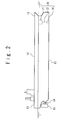
FIG. 2 is a side view of a ship provided with a frictional resistance reducing device according to a first embodiment of the present invention; -
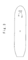
FIG. 3 is a bottom view of the ship provided with the frictional resistance reducing device according to the first embodiment; -
FIG. 4 is a perspective view of a gas room provided for the frictional resistance reducing device according to the first embodiment; -
FIG. 5A is a plan view of the gas room provided for the frictional resistance reducing device according to the first embodiment; -
FIG. 5B is a side sectional view of the gas room provided for the frictional resistance reducing device according to the first embodiment along the line A-A ofFIG. 5A ; -
FIG. 5C is a sectional view of the gas room provided for the frictional resistance reducing device according to the first embodiment along the line B-B ofFIG. 5A ; -
FIG. 5D is a sectional view of the gas room provided for the frictional resistance reducing device according to the first embodiment along the line C-C ofFIG. 5A ; -
FIG. 6A is a side sectional view of a first modification of the gas room according to the first embodiment along the line A-A ofFIG. 5A ; -
FIG. 6B is s sectional view of the first modification of the gas room according to the first embodiment along the line C-C ofFIG. 5A ; -
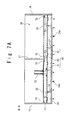
FIG. 7A is a side sectional view of a second modification of the gas room according to first embodiment along the line A-A ofFIG. 5A ; -
FIG. 7B is a sectional view of the second modification of the gas room according to first embodiment along the line C-C ofFIG. 5A ; -
FIG. 8A is a plan view of the gas room provided for the frictional resistance reducing device according to a second embodiment of the present invention; -
FIG. 8B is a sectional view of the gas room provided for the frictional resistance reducing device according to the second embodiment of the present invention along the line D-D ofFIG. 8A ; -
FIG. 8C is a sectional view of the gas room provided for the frictional resistance reducing device according to the second embodiment of the present invention along the line E-E ofFIG. 8A ; and -
FIG. 8D is a sectional view of the gas room provided for the frictional resistance reducing device according to the second embodiment of the present invention along the line F-F ofFIG. 8A . - Hereinafter, a ship provided with a frictional resistance reducing device according to the present invention will be described in detail with reference to the attached drawings.
- Referring to
FIG. 2 , a ship according to a first embodiment of the present invention is provided with ahull 10 and a frictionalresistance reducing device 20. Thehull 10 is provided with abow 11, a stern 12, and a bottom in aship 13. Thepropeller 14 and arudder 15 are provided for the stern 12. The frictionalresistance reducing device 20 is provided with anair feeder 21, anair supply pipe 22 and agas room 30. Theaerial feeder 21 is a compressor or a blower. Theair feeder 21 and thegas room 30 are connected through theair supply pipe 22. Thegas room 30 is provided on the side ofbow 11 of the bottom of theship 13. - Referring to
FIG. 3 , a plurality ofair blowing holes 34a are formed in thegas room 30 to be opened in the bottom of theship 13. The frictionalresistance reducing device 20 blows air from theair blowing holes 34a into water when theship 13 navigate. Thus, an air bubble flow is formed along the bottom of theship 13 to reduce the frictional resistance of thehull 10. - Referring to
FIG. 4 , thehull 10 is provided withlongitudinal frames longitudinal frames longitudinal frame 16 to be described later are partitions which divide a space of thehull 10 into a width direction Y of the hull 10 (a direction from the port side to the starboard side). Thegas room 30 is provided in thehull 10 to cross the longitudinal frame 17 (to pass through the longitudinal frame 17) and to extend to the width direction Y. The frictionalresistance reducing device 20 is provided with a scatteringmember 40 which is arranged in thegas room 30. The scatteringmember 40 crosses thelongitudinal frame 17 and extends the width direction Y. Therefore, the longitudinal directions of thegas room 30 and the scatteringmember 40 are parallel to the width direction Y. It should be noted that X inFIG. 4 shows a longitudinal direction (a direction from the bow to the stern) of thehull 10. Theair supply pipe 22 is connected with thegas room 30 from an upper side. A part of theair supply pipe 22 which is connected with thegas room 30 extends into the upper and lower directions. - Referring to
FIG. 5A , thegas room 30 will be described. Thehull 10 is further provided with thelongitudinal frame 16. Thelongitudinal frame 16 is arranged on the port side of thelongitudinal frame 17. Thelongitudinal frame 18 is arranged on the starboard side of thelongitudinal frame 17. Thegas room 30 is provided with anupper member 31, alongitudinal side member 32 on the side ofbow 11, alongitudinal side member 33 on the side of stern 12, andlids opening 31a is formed in a part of theupper member 31 on the port side from thelongitudinal frame 17. Anopening 31b is formed in a part of theupper member 31 on the starboard side from thelongitudinal frame 17. Theopenings gas room 30 and the internal space of thehull 10. Thelid 35 is attached to theopening 31a bybolts 70. Thelid 36 is attached to theopening 31b bybolts 70. Therefore, it is possible to remove thelids air supply pipe 22 is connected with thelid 35. - Referring to
FIG. 5B , thegas room 30 will be described. Thegas room 30 is provided with abottom member 34 in which the plurality ofair blowing holes 34a are formed. Thebottom member 34 is formed as the bottom of theship 13. The plurality ofair blowing holes 34a are arranged in the width direction Y. Thelongitudinal frame 16 forms a port side member on the port side of thegas room 30. Thelongitudinal frame 18 forms a starboard side member on the starboard side of thegas room 30. The scatteringmember 40 has a block structure which is provided with afirst part 41, asecond part 42 and amiddle part 43. Thefirst part 41 forms a part of the scatteringmember 40 on the port side from thelongitudinal frame 17. Thesecond part 42 forms a part of the scatteringmember 40 on the starboard side from thelongitudinal frame 17. Themiddle part 43 forms a part of the scatteringmember 40 between thefirst part 41 andsecond part 42. Thefirst part 41 has a size enough to pass through theopening 31a. Thefirst part 41 is attached to thelid 35 through supportingmembers 51. Thesecond part 42 has a size enough to pass through theopening 31b. Thesecond part 42 is attached to thelid 36 through supportingmembers 52. Themiddle part 43 is supported by thelongitudinal frame 17 through a supportingmember 53. Thefirst part 41 and thesecond part 42 can be separated from the scatteringmember 40. A connection port of theair supply pipe 22 and thelid 35 is arranged straightly above the scattering member 40 (the first part 41). The plurality ofair blowing holes 34a are arranged straightly below the scatteringmember 40. - Referring to
FIGS. 5C and 5D , aslit hole 61 is formed between the scatteringmember 40 and thelongitudinal side member 32 to extend in the width direction Y. Aslit hole 62 is formed between the scatteringmember 40 and thelongitudinal side member 33 to extend in the width direction Y. Theslit hole 61 is arranged on the side ofbow 11 of the scatteringmember 40. Theslit hole 62 is arranged on the side of the stern 12 of the scatteringmember 40. - The
air feeder 21 supplies air into thegas room 30 through theair supply pipe 22. The air is blown from theair supply pipe 22 into thegas room 30 as a flow in a downward direction for the scattering member 40 (the first part 41). The air blown into thegas room 30 from theair supply pipe 22 hits the scatteringmember 40 and scatters into the width direction Y, and moreover after passing theslit hole 61 or theslit hole 62, is blown from theair blowing holes 34a into water. Therefore, an air bubble flow, which is uniform in the width direction Y, is formed along the bottom of theship 13. - In the frictional
resistance reducing device 20 according to the present embodiment, the air bubble flow which is wide in the width direction Y can be formed by thesingle gas room 30 because thegas room 30 cross thelongitudinal frame 17 to extend in the width direction Y. Therefore, the number ofgas rooms 30 which are necessary to form the air bubble flow which covers the whole width of the bottom of theship 13 in the width direction Y may be few, and the number ofair supply pipes 22 which are provided everygas room 30 may be few. According to the present embodiment, it is not necessary to provide the many air supply pipes in thehull 10 where the space is limited. - Moreover, in the frictional
resistance reducing device 20 according to the present embodiment, theopening longitudinal frames 16 to 18. It is possible to separate thefirst part 41 and thesecond part 42 from the scatteringmember 40 and to take them out of the gas room 30 (in the hull 10) through theopenings gas room 30 and the scatteringmember 40 is easy at the time of the docking. Therefore, the frictionalresistance reducing device 20 according to the present embodiment is superior in the maintenance. - Moreover, because the
lid 35 and thefirst part 41 are coupled by the supportingmember 51, and thelid 36 and thesecond part 42 are coupled by the supportingmember 52, thefirst part 41 is taken out from thegas room 30 at the same time as removing thelid 35, and thesecond part 42 is taken out from thegas room 30 at the same time as removing thelid 36. Therefore, works for the maintenance can be little. - Next, a first modification of the first embodiment will be described with reference to
FIGS. 6A and6B . The frictionalresistance reducing device 20 according to the first modification is same as the frictionalresistance reducing device 20 according to the first embodiment, excluding the following description. - In the
gas room 30 according to the first modification, thefirst part 41 of the scatteringmember 40 is not attached to thelid 35 and thesecond part 42 of the scatteringmember 40 is not attached to thelid 36. A supportingmembers 54 is provided for as the longitudinal frame 16 (longitudinal side member of the gas room 30) on the port side and a supportingmember 55 is provided for the longitudinal frame 18 (longitudinal side member of the gas room 30) on the starboard side. Thefirst part 41 is attached to the supportingmember 54 and themiddle part 43 bybolts 70, and thesecond part 42 is attached to the supportingmember 55 and themiddle part 43 bybolts 70. Therefore, thefirst part 41 and thesecond part 42 can be detachable. - In the maintenance of the
gas room 30 according to the first modification, thefirst part 41 is taken out of the gas room 30 (in the hull 10) through theopenings 31a after removing thelid 35. Thesecond part 42 is taken out of the gas room 30 (in the hull 10) through theopening 31b after removing thelid 36. - Next, referring to
FIGS. 7A and7B , a second modification of the first embodiment will be described. The frictionalresistance reducing device 20 according to the second modification is same as the above frictionalresistance reducing device 20 according to the first embodiment, excluding the following explanation. - In the
gas room 30 according to the second modification, thefirst part 41 of the scatteringmember 40 is not attached to thelid 35 and thesecond part 42 of the scatteringmember 40 is not attached to thelid 36. Supportingmembers 56 are provided for a part of the bottom 34 on the port side from thelongitudinal frame 17 and supportingmembers 57 are provided for a part of the bottom 34 on the starboard side from thelongitudinal frame 17. Thefirst part 41 is attached to the supportingmembers 56 bybolts 70 and thesecond part 42 is attached to the supportingmembers 57 bybolts 70. Therefore, thefirst part 41 and thesecond part 42 are detachable. - In the maintenance of the
gas room 30 according to the second modification, thefirst part 41 is taken out of the gas room 30 (in the hull 10) through theopenings 31a after removing thelid 35. Thesecond part 42 is taken out of the gas room 30 (in the hull 10) through theopening 31b after removing thelid 36. - It should be noted that the
air supply pipe 22 may be connected with thelid 36 in the first embodiment, and the first modification and the second modification of the present embodiment. - Referring to
FIGS. 8A to 8D , the frictionalresistance reducing device 20 according to the second embodiment of the present invention will be described. The frictionalresistance reducing device 20 according to the present embodiment is same as the frictionalresistance reducing device 20 according to the first embodiment, excluding the following description. - Referring to
FIG. 8A , thegas room 30 according to the present embodiment will be described. Thegas room 30 is provided withlids upper member 31 of thegas room 30 and any lid attached to the opening is not provided. Theair supply pipe 22 is connected with a part of theupper member 31 on the port side from thelongitudinal frame 17. - Referring to
FIG. 8B , thegas room 30 according to the present embodiment will be described. Anopening 33a is formed in a part of thelongitudinal side member 33 on the port side from thelongitudinal frame 17. Anopening 33b is formed in a part of thelongitudinal side member 33 on the starboard side from thelongitudinal frame 17. Theopenings gas room 30 and the internal space of thehull 10, respectively. Thelid 37 is attached to theopening 33a bybolts 70. Thelid 38 is attached to theopening 33b bybolts 70. Therefore, thelids - Referring to
FIG. 8C , thefirst part 41 of the scatteringmember 40 has a size enough to pass through theopening 33a and thesecond part 42 of the scatteringmember 40 has a size enough to pass though theopening 33b. Supportingmembers 58 are provided for a part of theupper member 31 on the port side from thelongitudinal frame 17 and supportingmembers 59 are provided for a part of theupper member 31 on the starboard side from thelongitudinal frame 17. Thefirst part 41 is attached to the supportingmember 58 bybolts 70 and thesecond part 42 is attached to the supportingmember 59 bybolts 70. Therefore, thefirst part 41 and thesecond part 42 are detachable. -
FIG. 8D shows an attachment structure of thesecond part 42 to theupper member 31. Thefirst part 41 is attached to theupper member 31, like thesecond part 42. - In the frictional
resistance reducing device 20 according to the present embodiment, because thegas room 30 crosses thelongitudinal frame 17 and extends to the width direction Y, the air bubble flow wide in the width direction Y can be formed by thesingle gas room 30. Therefore, the number ofgas rooms 30 which are necessary to form the air bubble flow which covers the whole width of the bottom of theship 13 in the width direction Y may be few. The number ofair supply pipes 22 which are provided for everygas room 30 may be few. According to the present embodiment, it is not necessary to arrange many air supply pipes in thehull 10 with a limited space. - Moreover, in the frictional
resistance reducing device 20 according to the present embodiment, theopening gas room 30 is provided between adjacent two of thelongitudinal frames 16 to 18. It is possible to separate thefirst part 41 and thesecond part 42 from the scatteringmember 40 and to take them out of the gas room 30 (in the hull 10) through theopenings gas room 30 and the scatteringmember 40 at the time of the docking. Therefore, the frictionalresistance reducing device 20 according to the present embodiment is superior in the maintenance. - Moreover, because the
air supply pipe 22 is connected with a portion of thegas room 30 other than thelids lids - In the present embodiment, like the first modification of the first embodiment, the
first part 41 may be supported by thelongitudinal side member 16 and themiddle part 43 in thegas room 30. Thesecond part 42 may be supported by thelongitudinal side member 18 and themiddle part 43 in thegas room 30. Also, in the present embodiment, like the second modification of the first embodiment, thefirst part 41 and thesecond part 42 may be supported to the bottom 34. - In the present embodiment, the
air supply pipe 22 may be connected with a portion of theupper member 31 on the starboard side from thelongitudinal frame 17. - In the present embodiment, two openings may be provided for the
longitudinal side member 32, instead of that theopenings longitudinal side member 33. - In the first and second embodiments, slit holes may be provided for the bottom 34 to extend into the width direction Y, instead of the plurality of
air blowing holes 34a. - In the first and second embodiments, the
gas room 30 may cross a plurality of longitudinal frames to extend into the width direction Y. - As described above, the embodiments of the present invention have been described. However, the present invention is not limited to the embodiments. Various modifications to the above embodiments can be carried out. Also, the above embodiments may be combined with each other.
- This application claims a priority on convention based on Japanese Patent Application No
2009-245515 filed on October 26, 2009
Claims (6)
- A frictional resistance reducing device of a ship, comprising:a gas room provided in a hull to cross a longitudinal frame and to extend into a width direction of a hull;a scattering member arranged in said gas room to cross said longitudinal frame and to extend into the width direction; andan air supply pipe connected with said gas room,wherein air blown into said gas room from said air supply pipe hits said scattering member and is scattered into the width direction and then blown from an air blowing hole provided in a bottom of said gas room after into water.
- The frictional resistance reducing device according to claim 1, wherein a first opening is provided in a portion of said gas room on a port side from said longitudinal frame to connect an internal space of the hull and an internal space of said gas room,
wherein a second opening is provided in another portion of said gas room on a starboard side from said longitudinal frame to connect the internal space of the hull and the internal space of said gas room,
wherein a first lid is provided for said first opening, and a second lid is provided for said second opening,
wherein a first part of said scattering member which is a part of said scattering member on the port side from said longitudinal frame, and a second part of said scattering member which is a part of said scattering member on the starboard side from said longitudinal frame can be separated from the scattering member, and
wherein said scattering member first part has such a size that said scattering member first part is possible to pass through said first opening, and said scattering member second part is such a size that said scattering member second part is possible to pass through said second opening. - The frictional resistance reducing device according to claim 2, wherein said first opening and said second opening are formed in an upper member of said gas room, and said air supply pipe is connected with said first lid or said second lid.
- The frictional resistance reducing device according to claim 3, wherein said scattering member first part is attached to said first lid, and said scattering member second part is attached to said second lid.
- The frictional resistance reducing device of according to claim 2, wherein said first opening and said second opening are formed in a longitudinal side member in a longitudinal direction of said gas room,
wherein said longitudinal side member is a side member of said gas room on a bow side or a stern side of the gas room, and
wherein said air supply pipe is connected with an upper member of said gas room. - The frictional resistance reducing device according to any of claims 1 to 5, wherein a bow side slit hole is formed on a bow side of said scattering member to extend into the width direction,
wherein a stern side slit hole is formed on a stern side of said scattering member to extend into the width direction, and
wherein the air blown into said gas room from said air supply pipe passes through the bow side slit hole or the stern side slit and is blown from said air blowing hole into the water.
Applications Claiming Priority (2)
| Application Number | Priority Date | Filing Date | Title |
|---|---|---|---|
| JP2009245515A JP5314565B2 (en) | 2009-10-26 | 2009-10-26 | Ship resistance reduction device |
| PCT/JP2010/067064 WO2011052337A1 (en) | 2009-10-26 | 2010-09-30 | Ship resistance-reduction device |
Publications (3)
| Publication Number | Publication Date |
|---|---|
| EP2495163A1 true EP2495163A1 (en) | 2012-09-05 |
| EP2495163A4 EP2495163A4 (en) | 2013-04-17 |
| EP2495163B1 EP2495163B1 (en) | 2015-04-01 |
Family
ID=43921765
Family Applications (1)
| Application Number | Title | Priority Date | Filing Date |
|---|---|---|---|
| EP10826471.4A Not-in-force EP2495163B1 (en) | 2009-10-26 | 2010-09-30 | Ship resistance-reduction device |
Country Status (6)
| Country | Link |
|---|---|
| US (1) | US8820256B2 (en) |
| EP (1) | EP2495163B1 (en) |
| JP (1) | JP5314565B2 (en) |
| KR (1) | KR101341747B1 (en) |
| CN (1) | CN102448807B (en) |
| WO (1) | WO2011052337A1 (en) |
Cited By (1)
| Publication number | Priority date | Publication date | Assignee | Title |
|---|---|---|---|---|
| CN105206143A (en) * | 2015-09-11 | 2015-12-30 | 西北工业大学 | Air film resistance reducing model based on wettability regulation and manufacturing method thereof |
Families Citing this family (16)
| Publication number | Priority date | Publication date | Assignee | Title |
|---|---|---|---|---|
| JP2014227089A (en) * | 2013-05-23 | 2014-12-08 | 三菱重工業株式会社 | Ship remodeling method and frictional resistance reduction ship |
| KR101630574B1 (en) * | 2014-04-02 | 2016-06-15 | 현대중공업 주식회사 | Air injecting apparatus protruding from bottom plate of ship toward seawater |
| KR101595701B1 (en) * | 2015-07-02 | 2016-02-19 | 현대중공업 주식회사 | Air lubrication system having inner chamber for ship |
| EP3290325B1 (en) * | 2016-08-30 | 2019-05-22 | Silverstream Technologies B.V. | Air lubrication system with a wave deflector for a vessel |
| CN106741586B (en) * | 2016-12-22 | 2019-01-04 | 浙江大学 | A kind of ship water jet constraint bubble drag-reduction structure |
| JP6655563B2 (en) * | 2017-01-31 | 2020-02-26 | 三菱重工業株式会社 | Ship friction reduction device |
| JP6655564B2 (en) * | 2017-01-31 | 2020-02-26 | 三菱重工業株式会社 | Ship friction reduction device |
| CN108128401A (en) * | 2017-11-23 | 2018-06-08 | 中国船舶科学研究中心上海分部 | The general voltage-stablizer of gas lid |
| CN108001610B (en) * | 2017-11-23 | 2024-04-23 | 中船(上海)节能技术有限公司 | Gas lubrication drag reduction and energy saving device |
| KR102747379B1 (en) * | 2017-12-22 | 2024-12-26 | 켈라 미카엘 오 | Cladding to reduce viscosity drag |
| CN108177724A (en) * | 2018-01-12 | 2018-06-19 | 中船重工船舶设计研究中心有限公司 | A kind of voltage stabilizing cavity configuration and installation method for resistance reduction by air cavity technology |
| CN112238922A (en) * | 2019-07-17 | 2021-01-19 | 章洪 | Supercavitation high-speed ship |
| CN111959675B (en) * | 2020-08-21 | 2021-05-04 | 中国船舶科学研究中心 | A device for generating drag reduction and generation of downstream jet air layer for ships |
| CN112519953A (en) * | 2020-11-10 | 2021-03-19 | 中船重工(上海)节能技术发展有限公司 | Gas layer drag reduction ship |
| CN112793709A (en) * | 2020-12-28 | 2021-05-14 | 中船重工(上海)节能技术发展有限公司 | Air injection structure of air layer resistance reducing device, ship air layer resistance reducing system and air layer resistance reducing ship |
| CN116476971B (en) * | 2023-06-09 | 2025-04-11 | 浙江大学 | A bubble drag reduction system and a ship comprising the same |
Family Cites Families (17)
| Publication number | Priority date | Publication date | Assignee | Title |
|---|---|---|---|---|
| US780122A (en) * | 1904-04-28 | 1905-01-17 | Hans Nelson | Air apparatus for vessels. |
| GB1190621A (en) * | 1967-04-10 | 1970-05-06 | John Wakelam Grundy | Improvements in or relating to Ships and Boats. |
| JPS4835557B1 (en) * | 1968-11-26 | 1973-10-29 | ||
| JPS5229511B2 (en) | 1971-09-07 | 1977-08-02 | ||
| NL190717C (en) * | 1983-06-07 | 1994-07-18 | Meijer Sjoerd | Vessel with diminished draft. |
| JPS60139586A (en) | 1983-12-26 | 1985-07-24 | Ishikawajima Harima Heavy Ind Co Ltd | Frictional resistance reducer for shipping |
| JPH09207873A (en) | 1996-01-31 | 1997-08-12 | Yoji Kato | Micro bubble generator |
| JPH1024891A (en) * | 1996-07-08 | 1998-01-27 | Ishikawajima Harima Heavy Ind Co Ltd | Ship friction reduction device |
| JPH11227675A (en) * | 1998-02-13 | 1999-08-24 | Ishikawajima Harima Heavy Ind Co Ltd | Air blower for ship with reduced frictional resistance |
| CA2244615A1 (en) | 1997-08-22 | 1999-02-22 | Ishikawajima-Harima Heavy Industries Co., Ltd. | Friction-reducing ship with compressed air generation apparatus, friction reduction apparatus and gas jetting device |
| JPH11291973A (en) | 1998-04-06 | 1999-10-26 | Ishikawajima Harima Heavy Ind Co Ltd | Air blower for ship with reduced frictional resistance |
| JPH11301570A (en) | 1998-04-20 | 1999-11-02 | Ishikawajima Harima Heavy Ind Co Ltd | Air blower for ship with reduced frictional resistance |
| US6789491B2 (en) * | 2000-04-03 | 2004-09-14 | Ishikawajima-Harima Heavy Industries Co., Ltd. | Friction reducing ship and method for reducing frictional resistance |
| JP4953296B2 (en) * | 2006-12-08 | 2012-06-13 | 独立行政法人海上技術安全研究所 | Hull frictional resistance reduction device |
| JP4835557B2 (en) | 2007-09-14 | 2011-12-14 | トヨタ自動車株式会社 | Blow-by gas reduction device for dry sump engine |
| JP2009245515A (en) | 2008-03-31 | 2009-10-22 | Fujifilm Corp | Magnetic recording medium, surface modifier for magnetic powder, and magnetic coating material including same |
| JP4959667B2 (en) | 2008-11-21 | 2012-06-27 | 三菱重工業株式会社 | Hull frictional resistance reduction device |
-
2009
- 2009-10-26 JP JP2009245515A patent/JP5314565B2/en active Active
-
2010
- 2010-09-30 WO PCT/JP2010/067064 patent/WO2011052337A1/en not_active Ceased
- 2010-09-30 US US13/376,221 patent/US8820256B2/en not_active Expired - Fee Related
- 2010-09-30 KR KR1020117028699A patent/KR101341747B1/en not_active Expired - Fee Related
- 2010-09-30 CN CN201080023758.7A patent/CN102448807B/en not_active Expired - Fee Related
- 2010-09-30 EP EP10826471.4A patent/EP2495163B1/en not_active Not-in-force
Cited By (1)
| Publication number | Priority date | Publication date | Assignee | Title |
|---|---|---|---|---|
| CN105206143A (en) * | 2015-09-11 | 2015-12-30 | 西北工业大学 | Air film resistance reducing model based on wettability regulation and manufacturing method thereof |
Also Published As
| Publication number | Publication date |
|---|---|
| US8820256B2 (en) | 2014-09-02 |
| WO2011052337A1 (en) | 2011-05-05 |
| US20120097089A1 (en) | 2012-04-26 |
| JP5314565B2 (en) | 2013-10-16 |
| CN102448807B (en) | 2015-01-28 |
| CN102448807A (en) | 2012-05-09 |
| KR20120023731A (en) | 2012-03-13 |
| EP2495163B1 (en) | 2015-04-01 |
| KR101341747B1 (en) | 2013-12-16 |
| EP2495163A4 (en) | 2013-04-17 |
| JP2011088605A (en) | 2011-05-06 |
Similar Documents
| Publication | Publication Date | Title |
|---|---|---|
| EP2495163B1 (en) | Ship resistance-reduction device | |
| JP5606128B2 (en) | Ship bubble recovery device | |
| JP5714098B2 (en) | Friction resistance reduction type ship and ship friction resistance reduction device | |
| EP2623410B1 (en) | Air lubrication system for ship | |
| JP5705486B2 (en) | Ship air lubrication system | |
| CN104755369B (en) | Ships with reduced frictional resistance | |
| CN103826967A (en) | Method for manufacturing gas-lubricated ship, and method for manufacturing gas-discharging chamber | |
| WO2014087718A1 (en) | Seawater suction box and ship | |
| JP6044930B2 (en) | Air blowing device for air lubrication and ship | |
| JP6413176B2 (en) | Ship | |
| JP5448741B2 (en) | Ship resistance reduction device | |
| JP2012017022A (en) | Wind pressure resistance reducing structure for ship, and the ship | |
| JP6143165B2 (en) | Ship frictional resistance reduction device | |
| JP2003160091A (en) | Ship friction reduction device | |
| JP2011136609A (en) | Resistance reducing device of ship | |
| JPH11291972A (en) | Friction drag reduction ship | |
| JP2014144776A (en) | Air bubble recovery device of watercraft | |
| JP5829664B2 (en) | Ship resistance reduction device | |
| JPH0872783A (en) | Wave impact buffer of catamaran ship | |
| JP2000203485A (en) | Friction drag reduction ship | |
| US20180162490A1 (en) | A vessel, especially a drillship, provided with a moon pool |
Legal Events
| Date | Code | Title | Description |
|---|---|---|---|
| PUAI | Public reference made under article 153(3) epc to a published international application that has entered the european phase |
Free format text: ORIGINAL CODE: 0009012 |
|
| 17P | Request for examination filed |
Effective date: 20111205 |
|
| AK | Designated contracting states |
Kind code of ref document: A1 Designated state(s): AL AT BE BG CH CY CZ DE DK EE ES FI FR GB GR HR HU IE IS IT LI LT LU LV MC MK MT NL NO PL PT RO SE SI SK SM TR |
|
| DAX | Request for extension of the european patent (deleted) | ||
| A4 | Supplementary search report drawn up and despatched |
Effective date: 20130315 |
|
| RIC1 | Information provided on ipc code assigned before grant |
Ipc: B63B 1/38 20060101AFI20130311BHEP |
|
| GRAP | Despatch of communication of intention to grant a patent |
Free format text: ORIGINAL CODE: EPIDOSNIGR1 |
|
| INTG | Intention to grant announced |
Effective date: 20141023 |
|
| GRAS | Grant fee paid |
Free format text: ORIGINAL CODE: EPIDOSNIGR3 |
|
| GRAA | (expected) grant |
Free format text: ORIGINAL CODE: 0009210 |
|
| AK | Designated contracting states |
Kind code of ref document: B1 Designated state(s): AL AT BE BG CH CY CZ DE DK EE ES FI FR GB GR HR HU IE IS IT LI LT LU LV MC MK MT NL NO PL PT RO SE SI SK SM TR |
|
| REG | Reference to a national code |
Ref country code: GB Ref legal event code: FG4D |
|
| REG | Reference to a national code |
Ref country code: CH Ref legal event code: EP |
|
| REG | Reference to a national code |
Ref country code: IE Ref legal event code: FG4D |
|
| REG | Reference to a national code |
Ref country code: DE Ref legal event code: R096 Ref document number: 602010023660 Country of ref document: DE Effective date: 20150513 |
|
| REG | Reference to a national code |
Ref country code: AT Ref legal event code: REF Ref document number: 718906 Country of ref document: AT Kind code of ref document: T Effective date: 20150515 |
|
| REG | Reference to a national code |
Ref country code: NL Ref legal event code: VDEP Effective date: 20150401 |
|
| REG | Reference to a national code |
Ref country code: AT Ref legal event code: MK05 Ref document number: 718906 Country of ref document: AT Kind code of ref document: T Effective date: 20150401 |
|
| REG | Reference to a national code |
Ref country code: LT Ref legal event code: MG4D |
|
| PG25 | Lapsed in a contracting state [announced via postgrant information from national office to epo] |
Ref country code: NL Free format text: LAPSE BECAUSE OF FAILURE TO SUBMIT A TRANSLATION OF THE DESCRIPTION OR TO PAY THE FEE WITHIN THE PRESCRIBED TIME-LIMIT Effective date: 20150401 |
|
| PG25 | Lapsed in a contracting state [announced via postgrant information from national office to epo] |
Ref country code: ES Free format text: LAPSE BECAUSE OF FAILURE TO SUBMIT A TRANSLATION OF THE DESCRIPTION OR TO PAY THE FEE WITHIN THE PRESCRIBED TIME-LIMIT Effective date: 20150401 Ref country code: NO Free format text: LAPSE BECAUSE OF FAILURE TO SUBMIT A TRANSLATION OF THE DESCRIPTION OR TO PAY THE FEE WITHIN THE PRESCRIBED TIME-LIMIT Effective date: 20150701 Ref country code: CZ Free format text: LAPSE BECAUSE OF FAILURE TO SUBMIT A TRANSLATION OF THE DESCRIPTION OR TO PAY THE FEE WITHIN THE PRESCRIBED TIME-LIMIT Effective date: 20150401 Ref country code: HR Free format text: LAPSE BECAUSE OF FAILURE TO SUBMIT A TRANSLATION OF THE DESCRIPTION OR TO PAY THE FEE WITHIN THE PRESCRIBED TIME-LIMIT Effective date: 20150401 Ref country code: LT Free format text: LAPSE BECAUSE OF FAILURE TO SUBMIT A TRANSLATION OF THE DESCRIPTION OR TO PAY THE FEE WITHIN THE PRESCRIBED TIME-LIMIT Effective date: 20150401 Ref country code: PT Free format text: LAPSE BECAUSE OF FAILURE TO SUBMIT A TRANSLATION OF THE DESCRIPTION OR TO PAY THE FEE WITHIN THE PRESCRIBED TIME-LIMIT Effective date: 20150803 |
|
| PG25 | Lapsed in a contracting state [announced via postgrant information from national office to epo] |
Ref country code: GR Free format text: LAPSE BECAUSE OF FAILURE TO SUBMIT A TRANSLATION OF THE DESCRIPTION OR TO PAY THE FEE WITHIN THE PRESCRIBED TIME-LIMIT Effective date: 20150702 Ref country code: IS Free format text: LAPSE BECAUSE OF FAILURE TO SUBMIT A TRANSLATION OF THE DESCRIPTION OR TO PAY THE FEE WITHIN THE PRESCRIBED TIME-LIMIT Effective date: 20150801 Ref country code: LV Free format text: LAPSE BECAUSE OF FAILURE TO SUBMIT A TRANSLATION OF THE DESCRIPTION OR TO PAY THE FEE WITHIN THE PRESCRIBED TIME-LIMIT Effective date: 20150401 Ref country code: AT Free format text: LAPSE BECAUSE OF FAILURE TO SUBMIT A TRANSLATION OF THE DESCRIPTION OR TO PAY THE FEE WITHIN THE PRESCRIBED TIME-LIMIT Effective date: 20150401 |
|
| REG | Reference to a national code |
Ref country code: DE Ref legal event code: R097 Ref document number: 602010023660 Country of ref document: DE |
|
| PG25 | Lapsed in a contracting state [announced via postgrant information from national office to epo] |
Ref country code: EE Free format text: LAPSE BECAUSE OF FAILURE TO SUBMIT A TRANSLATION OF THE DESCRIPTION OR TO PAY THE FEE WITHIN THE PRESCRIBED TIME-LIMIT Effective date: 20150401 Ref country code: DK Free format text: LAPSE BECAUSE OF FAILURE TO SUBMIT A TRANSLATION OF THE DESCRIPTION OR TO PAY THE FEE WITHIN THE PRESCRIBED TIME-LIMIT Effective date: 20150401 |
|
| PLBE | No opposition filed within time limit |
Free format text: ORIGINAL CODE: 0009261 |
|
| STAA | Information on the status of an ep patent application or granted ep patent |
Free format text: STATUS: NO OPPOSITION FILED WITHIN TIME LIMIT |
|
| PG25 | Lapsed in a contracting state [announced via postgrant information from national office to epo] |
Ref country code: PL Free format text: LAPSE BECAUSE OF FAILURE TO SUBMIT A TRANSLATION OF THE DESCRIPTION OR TO PAY THE FEE WITHIN THE PRESCRIBED TIME-LIMIT Effective date: 20150401 Ref country code: SK Free format text: LAPSE BECAUSE OF FAILURE TO SUBMIT A TRANSLATION OF THE DESCRIPTION OR TO PAY THE FEE WITHIN THE PRESCRIBED TIME-LIMIT Effective date: 20150401 Ref country code: RO Free format text: LAPSE BECAUSE OF NON-PAYMENT OF DUE FEES Effective date: 20150401 |
|
| 26N | No opposition filed |
Effective date: 20160105 |
|
| PG25 | Lapsed in a contracting state [announced via postgrant information from national office to epo] |
Ref country code: MC Free format text: LAPSE BECAUSE OF FAILURE TO SUBMIT A TRANSLATION OF THE DESCRIPTION OR TO PAY THE FEE WITHIN THE PRESCRIBED TIME-LIMIT Effective date: 20150401 Ref country code: LU Free format text: LAPSE BECAUSE OF FAILURE TO SUBMIT A TRANSLATION OF THE DESCRIPTION OR TO PAY THE FEE WITHIN THE PRESCRIBED TIME-LIMIT Effective date: 20150930 |
|
| REG | Reference to a national code |
Ref country code: CH Ref legal event code: PL |
|
| GBPC | Gb: european patent ceased through non-payment of renewal fee |
Effective date: 20150930 |
|
| PG25 | Lapsed in a contracting state [announced via postgrant information from national office to epo] |
Ref country code: SI Free format text: LAPSE BECAUSE OF FAILURE TO SUBMIT A TRANSLATION OF THE DESCRIPTION OR TO PAY THE FEE WITHIN THE PRESCRIBED TIME-LIMIT Effective date: 20150401 |
|
| REG | Reference to a national code |
Ref country code: IE Ref legal event code: MM4A |
|
| PG25 | Lapsed in a contracting state [announced via postgrant information from national office to epo] |
Ref country code: CH Free format text: LAPSE BECAUSE OF NON-PAYMENT OF DUE FEES Effective date: 20150930 Ref country code: IE Free format text: LAPSE BECAUSE OF NON-PAYMENT OF DUE FEES Effective date: 20150930 Ref country code: GB Free format text: LAPSE BECAUSE OF NON-PAYMENT OF DUE FEES Effective date: 20150930 Ref country code: LI Free format text: LAPSE BECAUSE OF NON-PAYMENT OF DUE FEES Effective date: 20150930 |
|
| REG | Reference to a national code |
Ref country code: FR Ref legal event code: PLFP Year of fee payment: 7 |
|
| PG25 | Lapsed in a contracting state [announced via postgrant information from national office to epo] |
Ref country code: BE Free format text: LAPSE BECAUSE OF FAILURE TO SUBMIT A TRANSLATION OF THE DESCRIPTION OR TO PAY THE FEE WITHIN THE PRESCRIBED TIME-LIMIT Effective date: 20150401 |
|
| PG25 | Lapsed in a contracting state [announced via postgrant information from national office to epo] |
Ref country code: MT Free format text: LAPSE BECAUSE OF FAILURE TO SUBMIT A TRANSLATION OF THE DESCRIPTION OR TO PAY THE FEE WITHIN THE PRESCRIBED TIME-LIMIT Effective date: 20150401 |
|
| PG25 | Lapsed in a contracting state [announced via postgrant information from national office to epo] |
Ref country code: BG Free format text: LAPSE BECAUSE OF FAILURE TO SUBMIT A TRANSLATION OF THE DESCRIPTION OR TO PAY THE FEE WITHIN THE PRESCRIBED TIME-LIMIT Effective date: 20150401 Ref country code: HU Free format text: LAPSE BECAUSE OF FAILURE TO SUBMIT A TRANSLATION OF THE DESCRIPTION OR TO PAY THE FEE WITHIN THE PRESCRIBED TIME-LIMIT; INVALID AB INITIO Effective date: 20100930 Ref country code: SM Free format text: LAPSE BECAUSE OF FAILURE TO SUBMIT A TRANSLATION OF THE DESCRIPTION OR TO PAY THE FEE WITHIN THE PRESCRIBED TIME-LIMIT Effective date: 20150401 |
|
| PG25 | Lapsed in a contracting state [announced via postgrant information from national office to epo] |
Ref country code: SE Free format text: LAPSE BECAUSE OF FAILURE TO SUBMIT A TRANSLATION OF THE DESCRIPTION OR TO PAY THE FEE WITHIN THE PRESCRIBED TIME-LIMIT Effective date: 20150401 Ref country code: CY Free format text: LAPSE BECAUSE OF FAILURE TO SUBMIT A TRANSLATION OF THE DESCRIPTION OR TO PAY THE FEE WITHIN THE PRESCRIBED TIME-LIMIT Effective date: 20150401 |
|
| REG | Reference to a national code |
Ref country code: FR Ref legal event code: PLFP Year of fee payment: 8 |
|
| PG25 | Lapsed in a contracting state [announced via postgrant information from national office to epo] |
Ref country code: TR Free format text: LAPSE BECAUSE OF FAILURE TO SUBMIT A TRANSLATION OF THE DESCRIPTION OR TO PAY THE FEE WITHIN THE PRESCRIBED TIME-LIMIT Effective date: 20150401 |
|
| PG25 | Lapsed in a contracting state [announced via postgrant information from national office to epo] |
Ref country code: MK Free format text: LAPSE BECAUSE OF FAILURE TO SUBMIT A TRANSLATION OF THE DESCRIPTION OR TO PAY THE FEE WITHIN THE PRESCRIBED TIME-LIMIT Effective date: 20150401 |
|
| REG | Reference to a national code |
Ref country code: DE Ref legal event code: R082 Ref document number: 602010023660 Country of ref document: DE Representative=s name: HENKEL & PARTNER MBB PATENTANWALTSKANZLEI, REC, DE Ref country code: DE Ref legal event code: R082 Ref document number: 602010023660 Country of ref document: DE Representative=s name: PATENTANWAELTE HENKEL, BREUER & PARTNER MBB, DE Ref country code: DE Ref legal event code: R081 Ref document number: 602010023660 Country of ref document: DE Owner name: MITSUBISHI SHIPBUILDING CO., LTD., YOKOHAMA-SH, JP Free format text: FORMER OWNER: MITSUBISHI HEAVY INDUSTRIES, LTD., TOKYO, JP |
|
| REG | Reference to a national code |
Ref country code: FR Ref legal event code: PLFP Year of fee payment: 9 |
|
| PG25 | Lapsed in a contracting state [announced via postgrant information from national office to epo] |
Ref country code: AL Free format text: LAPSE BECAUSE OF FAILURE TO SUBMIT A TRANSLATION OF THE DESCRIPTION OR TO PAY THE FEE WITHIN THE PRESCRIBED TIME-LIMIT Effective date: 20150401 |
|
| PGFP | Annual fee paid to national office [announced via postgrant information from national office to epo] |
Ref country code: FI Payment date: 20190909 Year of fee payment: 10 Ref country code: FR Payment date: 20190815 Year of fee payment: 10 |
|
| REG | Reference to a national code |
Ref country code: FI Ref legal event code: MAE |
|
| PG25 | Lapsed in a contracting state [announced via postgrant information from national office to epo] |
Ref country code: FI Free format text: LAPSE BECAUSE OF NON-PAYMENT OF DUE FEES Effective date: 20200930 |
|
| PG25 | Lapsed in a contracting state [announced via postgrant information from national office to epo] |
Ref country code: FR Free format text: LAPSE BECAUSE OF NON-PAYMENT OF DUE FEES Effective date: 20200930 |
|
| PGFP | Annual fee paid to national office [announced via postgrant information from national office to epo] |
Ref country code: IT Payment date: 20210811 Year of fee payment: 12 |
|
| PGFP | Annual fee paid to national office [announced via postgrant information from national office to epo] |
Ref country code: DE Payment date: 20210818 Year of fee payment: 12 |
|
| REG | Reference to a national code |
Ref country code: DE Ref legal event code: R119 Ref document number: 602010023660 Country of ref document: DE |
|
| PG25 | Lapsed in a contracting state [announced via postgrant information from national office to epo] |
Ref country code: DE Free format text: LAPSE BECAUSE OF NON-PAYMENT OF DUE FEES Effective date: 20230401 |
|
| PG25 | Lapsed in a contracting state [announced via postgrant information from national office to epo] |
Ref country code: IT Free format text: LAPSE BECAUSE OF NON-PAYMENT OF DUE FEES Effective date: 20220930 |