EP2495141A1 - Antenna device - Google Patents
Antenna device Download PDFInfo
- Publication number
- EP2495141A1 EP2495141A1 EP20120155295 EP12155295A EP2495141A1 EP 2495141 A1 EP2495141 A1 EP 2495141A1 EP 20120155295 EP20120155295 EP 20120155295 EP 12155295 A EP12155295 A EP 12155295A EP 2495141 A1 EP2495141 A1 EP 2495141A1
- Authority
- EP
- European Patent Office
- Prior art keywords
- cover
- substrate
- antenna
- key cylinder
- housing
- Prior art date
- Legal status (The legal status is an assumption and is not a legal conclusion. Google has not performed a legal analysis and makes no representation as to the accuracy of the status listed.)
- Granted
Links
- 239000000758 substrate Substances 0.000 claims abstract description 52
- 239000012780 transparent material Substances 0.000 claims abstract description 8
- 238000009434 installation Methods 0.000 description 11
- 230000008878 coupling Effects 0.000 description 5
- 238000010168 coupling process Methods 0.000 description 5
- 238000005859 coupling reaction Methods 0.000 description 5
- 239000011347 resin Substances 0.000 description 5
- 229920005989 resin Polymers 0.000 description 5
- 239000000463 material Substances 0.000 description 4
- 230000001105 regulatory effect Effects 0.000 description 3
- 238000002485 combustion reaction Methods 0.000 description 2
- 238000003780 insertion Methods 0.000 description 1
- 230000037431 insertion Effects 0.000 description 1
- 230000007246 mechanism Effects 0.000 description 1
- 230000004048 modification Effects 0.000 description 1
- 238000012986 modification Methods 0.000 description 1
Images


Classifications
-
- E—FIXED CONSTRUCTIONS
- E05—LOCKS; KEYS; WINDOW OR DOOR FITTINGS; SAFES
- E05B—LOCKS; ACCESSORIES THEREFOR; HANDCUFFS
- E05B85/00—Details of vehicle locks not provided for in groups E05B77/00 - E05B83/00
- E05B85/02—Lock casings
-
- H—ELECTRICITY
- H01—ELECTRIC ELEMENTS
- H01Q—ANTENNAS, i.e. RADIO AERIALS
- H01Q1/00—Details of, or arrangements associated with, antennas
- H01Q1/27—Adaptation for use in or on movable bodies
- H01Q1/32—Adaptation for use in or on road or rail vehicles
- H01Q1/3208—Adaptation for use in or on road or rail vehicles characterised by the application wherein the antenna is used
- H01Q1/3233—Adaptation for use in or on road or rail vehicles characterised by the application wherein the antenna is used particular used as part of a sensor or in a security system, e.g. for automotive radar, navigation systems
- H01Q1/3241—Adaptation for use in or on road or rail vehicles characterised by the application wherein the antenna is used particular used as part of a sensor or in a security system, e.g. for automotive radar, navigation systems particular used in keyless entry systems
-
- B—PERFORMING OPERATIONS; TRANSPORTING
- B60—VEHICLES IN GENERAL
- B60R—VEHICLES, VEHICLE FITTINGS, OR VEHICLE PARTS, NOT OTHERWISE PROVIDED FOR
- B60R25/00—Fittings or systems for preventing or indicating unauthorised use or theft of vehicles
- B60R25/01—Fittings or systems for preventing or indicating unauthorised use or theft of vehicles operating on vehicle systems or fittings, e.g. on doors, seats or windscreens
- B60R25/04—Fittings or systems for preventing or indicating unauthorised use or theft of vehicles operating on vehicle systems or fittings, e.g. on doors, seats or windscreens operating on the propulsion system, e.g. engine or drive motor
-
- B—PERFORMING OPERATIONS; TRANSPORTING
- B60—VEHICLES IN GENERAL
- B60R—VEHICLES, VEHICLE FITTINGS, OR VEHICLE PARTS, NOT OTHERWISE PROVIDED FOR
- B60R25/00—Fittings or systems for preventing or indicating unauthorised use or theft of vehicles
- B60R25/20—Means to switch the anti-theft system on or off
- B60R25/2063—Ignition switch geometry
-
- E—FIXED CONSTRUCTIONS
- E05—LOCKS; KEYS; WINDOW OR DOOR FITTINGS; SAFES
- E05B—LOCKS; ACCESSORIES THEREFOR; HANDCUFFS
- E05B81/00—Power-actuated vehicle locks
- E05B81/54—Electrical circuits
-
- H—ELECTRICITY
- H01—ELECTRIC ELEMENTS
- H01Q—ANTENNAS, i.e. RADIO AERIALS
- H01Q1/00—Details of, or arrangements associated with, antennas
- H01Q1/12—Supports; Mounting means
- H01Q1/22—Supports; Mounting means by structural association with other equipment or articles
- H01Q1/24—Supports; Mounting means by structural association with other equipment or articles with receiving set
-
- H—ELECTRICITY
- H01—ELECTRIC ELEMENTS
- H01Q—ANTENNAS, i.e. RADIO AERIALS
- H01Q7/00—Loop antennas with a substantially uniform current distribution around the loop and having a directional radiation pattern in a plane perpendicular to the plane of the loop
-
- B—PERFORMING OPERATIONS; TRANSPORTING
- B60—VEHICLES IN GENERAL
- B60Q—ARRANGEMENT OF SIGNALLING OR LIGHTING DEVICES, THE MOUNTING OR SUPPORTING THEREOF OR CIRCUITS THEREFOR, FOR VEHICLES IN GENERAL
- B60Q1/00—Arrangement of optical signalling or lighting devices, the mounting or supporting thereof or circuits therefor
- B60Q1/26—Arrangement of optical signalling or lighting devices, the mounting or supporting thereof or circuits therefor the devices being primarily intended to indicate the vehicle, or parts thereof, or to give signals, to other traffic
- B60Q1/2661—Arrangement of optical signalling or lighting devices, the mounting or supporting thereof or circuits therefor the devices being primarily intended to indicate the vehicle, or parts thereof, or to give signals, to other traffic mounted on parts having other functions
- B60Q1/2669—Arrangement of optical signalling or lighting devices, the mounting or supporting thereof or circuits therefor the devices being primarily intended to indicate the vehicle, or parts thereof, or to give signals, to other traffic mounted on parts having other functions on door or boot handles
Definitions
- the present invention relates to an antenna device that performs wireless communication with an electronic key.
- Immobilizer systems are installed in automobiles to prevent automobile theft by prohibiting starting of the engine.
- Japanese Laid-Open Patent Publication No. 2007-303171 describes such an immobilizer system.
- the immobilizer system of the publication includes a transponder arranged in an ignition key, a coil antenna arranged in a key cylinder, and a computer installed in a vehicle (steering column).
- the transponder of the ignition key transmits an ID code.
- the coil antenna in the key cylinder then receives the ID code from the transponder and transmits the ID code to the computer.
- the computer compares the received ID code with its ID code and permits starting of the engine when the two ID codes are in conformance. In this state, operation of the ignition key starts the engine.
- the immobilizer system of each automobile has a unique ID code, which differs from those of other automobiles.
- the correct key cylinder which incorporates electronic components, must be installed in each automobile.
- a label or the like can be attached to the key cylinder.
- erroneous installation may occur not only when installing the key cylinder in an automobile but also when installing electronic components in the key cylinder device. Nevertheless, the installation of the correct electronic components cannot be determined from the outer appearance of the key cylinder device. In this regard, there is still room for improvements.
- One embodiment of the present invention is an antenna device including an antenna that performs wireless communication with an electronic key.
- a substrate is connected to the antenna.
- a housing includes the antenna and the substrate.
- a cover is coupled to the housing to cover the substrate, which is exposed from the housing.
- the cover includes a part formed from a transparent material and facing at least part of the substrate.
- the substrate can be viewed through the transparent part of the cover.
- the color of the substrate or characters and numbers of a marking on the substrate regulated by law such as an approval number can be checked when assembling the antenna device or when coupling the assembled antenna device to a vehicle in a state in which the cover is coupled to the housing. This prevents erroneous installation of the antenna device.
- the antenna device is embodied in a key cylinder device 10.
- the key cylinder device 10 includes a cylinder holder 11, a key cylinder body 12, which is fitted into the key cylinder holder 11, and a cover 13, which covers the key cylinder holder 11 and the key cylinder body 12.
- the key cylinder holder 11 is fixed by a coupling piece 11 a to a steering column C of an automobile.
- the key cylinder body 12 includes a cylindrical sleeve 12a, and an annular flange 12b, which closes an opening of the sleeve 12a.
- the flange 12b has a diameter (outer diameter) that is slightly greater than a diameter (outer diameter) of the sleeve 12a.
- a keyway piece 12c which is rotatable relative to the flange 12b, projects from a central portion of the flange 12b.
- the keyway piece 12c is coupled in an integrally rotatable manner to a rotor that is arranged in the sleeve 12a.
- the rotor starts and stops operation of an internal combustion engine, which serves as a drive source.
- the keyway piece 12c which serves as an operation member, includes a keyway 12d for insertion of an ignition key K, which serves as an electronic key.
- the ignition key K is inserted into the keyway 12d and turned to synchronously rotate the rotor.
- the cover 13 includes a first cover 13A and a second cover 13B.
- the first cover 13A serves as a housing that covers an upper portion and front surface of the key cylinder body 12.
- the second cover 13B covers the first cover 13A from an outer side.
- the first cover 13A includes a first flange cover 20 and an antenna coil case 21, which is arranged on the front of the first flange cover 20.
- the first flange cover 20 is annular and covers the flange 12b while exposing a front surface of the keyway piece 12c, which includes the keyway 12d.
- the antenna coil case 21 is annular and extends around an opening of the first flange cover 20.
- the antenna coil case 21 includes a wound antenna coil, or antenna, which serves as an electronic device that performs wireless communication with an ignition key K (with a transponder arranged in the ignition key K).
- the first cover 13A includes a box-shaped electronic component compartment 22, which is arranged above the first flange cover 20 and extends in a direction opposite to the direction in which the antenna coil case 21 projects.
- a substrate 40 is arranged in the electronic component compartment 22.
- Various electronic elements, including an LED serving as a light source, are fixed and wired to the substrate 40.
- the antenna coil is electrically connected to the substrate 40.
- a rear surface (upper surface) of the substrate 40 includes a marking regulated by law such as an approval number required for a wireless authentication system.
- Tabs 23 are formed on left and right sides of the first cover 13A between the first flange cover 20 and the electronic component compartment 22.
- the first cover 13A is hooked by a hooking mechanism (not shown) to the key cylinder holder 11 and key cylinder body 12.
- the second cover 13B is formed from a transparent material such as a transparent resin.
- the second cover 13B includes a second flange cover 30 and a cylindrical wall 31, which projects from the front of the second flange cover 30.
- the second flange cover 30 is annular and covers the first flange cover 20 while exposing the front surface of the keyway piece 12c, which includes the keyway 12d.
- the cylindrical wall 31 is formed around an opening of the second flange cover 30. The cylindrical wall 31 is projected for an amount that is set so that a front end of the cylindrical wall 31 is flush with a front end of the antenna coil case 21 when the second cover 13B is coupled to the first cover 13A.
- the second flange cover 30 acts as a light guide that guides light from the LED serving as the light source arranged in the first cover 13A (or on the substrate 40).
- the second cover 13B includes a planar electronic component compartment cover 32, which is arranged above the second flange cover 30 and extends in the direction opposite to the direction in which the antenna coil case 21 projects.
- the electronic component compartment cover 32 includes a convex lens 50. Further, hooking holes 33 are formed in the left and right sides of the second cover 13B between the second flange cover 30 and the electronic component compartment cover 32.
- the second cover 13B is coupled to the first cover 13A with the second flange cover 30 arranged in correspondence with the first flange cover 20 and the electronic component compartment cover 32 arranged in correspondence with the electronic component compartment 22.
- the second flange cover 30 covers the first flange cover 20
- the cylindrical wall 31 covers the antenna coil case 21
- the electronic component compartment cover 32 covers the electronic component compartment 22.
- the convex lens 50 is arranged facing the substrate 40.
- the second flange cover 30, the cylindrical wall 31, and the electronic component compartment cover 32 are formed integrally with one another.
- the second cover 13B is formed from a transparent resin material.
- various electronic components and the like in the first cover 13A can be viewed. More specifically, the color of the substrate 40 or characters and numbers of a marking on the substrate 40 regulated by law such as an approval number required for a wireless authentication system can be checked when assembling the key cylinder device 10 and coupling the key cylinder device 10 to the steering column C. This prevents erroneous installation of the key cylinder device 10 in the vehicle.
- the electronic component compartment cover 32 which covers the electronic component compartment 22 accommodating the substrate 40, includes the convex lens 50. Accordingly, the characters and numbers on the substrate 40 are viewed through the convex lens 50. This magnifies the viewed characters and the like and allows for easy reading of the marked information. In other words, even if the characters and numbers on the substrate are small, the characters and numbers can easily be read. Thus, the amount of information marked on the substrate 40 can be increased.
- the key cylinder device 10 of the present embodiment has the advantages described below.
- a lenticular print 60 may be used in lieu of the convex lens 50.
- the lenticular print 60 includes a lenticular image and a lenticular lens 63.
- the lenticular image is a combination of two or more raw images (e.g., two raw images 61 and 62 in Fig. 3 ).
- the lenticular lens 63 is arranged on the lenticular image on a surface facing away from the substrate 40.
- Each of the raw images 61 and 62 is sliced into strips. Then, the strips of the raw images 61 and 62 are interlaced to form the lenticular image.
- the lenticular lens 63 is formed by an array of fine elongated convex lenses.
- the raw image 61 is a transparent image
- the raw image 62 is an information image including characters and numbers. This structure allows for one of the two raw images 61 and 62 to be viewed depending on the angle at which the lenticular lens 63 is viewed.
- the transparent raw image 61 allows for the substrate 40 to be checked.
- the information on the raw image 62 can be checked. Accordingly, when using the lenticular print 60 in lieu of the convex lens 50, more information can be included in the same region.
- the lenticular image can be formed by combining three or more raw images. In this case, one of the three or more raw images forms a transparent image.
- the above embodiment does not have to include the convex lens 50. Even in such a structure, the color of the substrate 40 and the characters and numbers of a marking on the substrate 40 can be checked when assembling the key cylinder device 10. This prevents erroneous installation of the key cylinder device 10.
- the second cover 13B does not necessarily have to be entirely formed from a transparent material as long as at least the electronic component compartment cover 32 is formed from a transparent material. Even in such a structure, the color of the substrate 40 and the characters and numbers of a marking on the substrate 40 can be checked when assembling the key cylinder device 10. This prevents erroneous installation of the key cylinder device 10. Further, only a portion of the electronic component compartment cover 32 corresponding to the substrate 40 may be transparent. Moreover, only a portion of the electronic component compartment cover 32 corresponding to part of the substrate 40 may be transparent. Even in such structures, more information such as the color of the substrate 40 can be obtained as compared with when the substrate cannot be viewed at all from the outer side.
- the first cover 13A includes the antenna coil case 21 and the electronic component compartment 22.
- the antenna coil case 21 and electronic component compartment 22 do not necessarily have to be formed integrally with the first cover 13A. That is, the antenna coil case 21 may be discrete from the electronic component compartment 22. In this case, it is only required that the member covering the electronic component compartment 22 be formed from a transparent resin material. Even in such a structure, the color of the substrate 40 and the characters and numbers of a marking on the substrate 40 can be checked when assembling the key cylinder device 10. This prevents erroneous installation of the key cylinder device 10.
- the second flange cover 30 may be discrete from the electronic component compartment cover 32.
- the electronic component compartment cover corresponds to a second cover.
- the ignition key K is inserted into the keyway 12d to turn the keyway piece 12c and start the engine.
- the key cylinder device 10 is not limited to such a structure.
- the present invention may be applied to a starting device that starts the engine when a switch is operated (pushed or turned) in a state in which electronic authentication of the electronic key and the vehicle is accomplished. This obtains the same advantages as the above embodiment.
- the drive source installed in the vehicle is an internal combustion engine.
- the drive source may be a motor for an electric vehicle or a motor and engine for a hybrid vehicle.
- the first cover 13A which serves as the housing, may also be formed from a transparent resin material such as the second cover 13B.
- a transparent resin material such as the second cover 13B.
- Such a structure allows for the substrate 40 to be viewed through the first cover 13A. In this case, the substrate 40 can be viewed more easily than when the first cover 13A is not formed from a transparent material. This further prevents erroneous installation of the key cylinder device 10.
- the antenna device is applied to a key cylinder device but may be applied to another device.
- the present invention may be applied to a door antenna device that is arranged in a vehicle door and performs wireless communication with an electronic key.
- a structure allows for configuration of a system that switches the vehicle doors between locked and unlocked states through wireless communication.
- the antenna device does not have to be used in a vehicle.
- the present invention may be embodied in an antenna device arranged near a household door to switch the door between locked and unlocked states through wireless communication.
- An antenna device (10) includes an antenna (21) that performs wireless communication with an electronic key (K).
- a substrate (40) is connected to the antenna (21).
- a housing (13A) includes the antenna (21) and the substrate (40).
- a cover (30) is coupled to the housing (13A) to cover the substrate (40), which is exposed from the housing (13A).
- the cover (30) includes a part formed from a transparent material and facing at least part of the substrate (40).
Landscapes
- Engineering & Computer Science (AREA)
- Mechanical Engineering (AREA)
- Computer Security & Cryptography (AREA)
- Radar, Positioning & Navigation (AREA)
- Remote Sensing (AREA)
- Lock And Its Accessories (AREA)
Abstract
Description
- The present invention relates to an antenna device that performs wireless communication with an electronic key.
- Immobilizer systems are installed in automobiles to prevent automobile theft by prohibiting starting of the engine. Japanese Laid-Open Patent Publication No.
2007-303171 - When a driver inserts the ignition key into the key cylinder device, the transponder of the ignition key transmits an ID code. The coil antenna in the key cylinder then receives the ID code from the transponder and transmits the ID code to the computer. The computer compares the received ID code with its ID code and permits starting of the engine when the two ID codes are in conformance. In this state, operation of the ignition key starts the engine.
- The immobilizer system of each automobile has a unique ID code, which differs from those of other automobiles. Thus, the correct key cylinder, which incorporates electronic components, must be installed in each automobile. To prevent erroneous installation, a label or the like can be attached to the key cylinder. However, erroneous installation may occur not only when installing the key cylinder in an automobile but also when installing electronic components in the key cylinder device. Nevertheless, the installation of the correct electronic components cannot be determined from the outer appearance of the key cylinder device. In this regard, there is still room for improvements.
- Accordingly, it is an object of the present invention to provide an antenna device that prevents erroneous installation.
- One embodiment of the present invention is an antenna device including an antenna that performs wireless communication with an electronic key. A substrate is connected to the antenna. A housing includes the antenna and the substrate. A cover is coupled to the housing to cover the substrate, which is exposed from the housing. The cover includes a part formed from a transparent material and facing at least part of the substrate.
- In this structure, the substrate can be viewed through the transparent part of the cover. Thus, the color of the substrate or characters and numbers of a marking on the substrate regulated by law such as an approval number can be checked when assembling the antenna device or when coupling the assembled antenna device to a vehicle in a state in which the cover is coupled to the housing. This prevents erroneous installation of the antenna device.
- Other embodiments and advantages of the present invention will become apparent from the following description, taken in conjunction with the accompanying drawings, illustrating by way of example the principles of the invention.
- The invention, together with objects and advantages thereof, may best be understood by reference to the following description of the presently preferred embodiments together with the accompanying drawings in which:
-
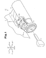
Fig. 1 is a perspective view showing a key cylinder device according to one embodiment of the present invention; -
Fig. 2 is an exploded perspective view showing the key cylinder device ofFig. 1 ; and -
Fig. 3 is a side view showing a modification of the key cylinder device. - One embodiment of an antenna device according to the present invention will now be described with reference to
Figs. 1 and2 . The antenna device is embodied in akey cylinder device 10. - . As shown in
Fig. 1 , thekey cylinder device 10 includes acylinder holder 11, akey cylinder body 12, which is fitted into thekey cylinder holder 11, and acover 13, which covers thekey cylinder holder 11 and thekey cylinder body 12. Thekey cylinder holder 11 is fixed by acoupling piece 11 a to a steering column C of an automobile. - As shown in
Fig. 2 , thekey cylinder body 12 includes acylindrical sleeve 12a, and anannular flange 12b, which closes an opening of thesleeve 12a. Theflange 12b has a diameter (outer diameter) that is slightly greater than a diameter (outer diameter) of thesleeve 12a. Akeyway piece 12c, which is rotatable relative to theflange 12b, projects from a central portion of theflange 12b. Thekeyway piece 12c is coupled in an integrally rotatable manner to a rotor that is arranged in thesleeve 12a. The rotor starts and stops operation of an internal combustion engine, which serves as a drive source. Thekeyway piece 12c, which serves as an operation member, includes akeyway 12d for insertion of an ignition key K, which serves as an electronic key. The ignition key K is inserted into thekeyway 12d and turned to synchronously rotate the rotor. - As shown in
Fig. 1 , thecover 13 includes afirst cover 13A and asecond cover 13B. Thefirst cover 13A serves as a housing that covers an upper portion and front surface of thekey cylinder body 12. Thesecond cover 13B covers thefirst cover 13A from an outer side. - As shown in
Fig. 2 , thefirst cover 13A includes afirst flange cover 20 and anantenna coil case 21, which is arranged on the front of thefirst flange cover 20. Thefirst flange cover 20 is annular and covers theflange 12b while exposing a front surface of thekeyway piece 12c, which includes thekeyway 12d. Theantenna coil case 21 is annular and extends around an opening of thefirst flange cover 20. Theantenna coil case 21 includes a wound antenna coil, or antenna, which serves as an electronic device that performs wireless communication with an ignition key K (with a transponder arranged in the ignition key K). Thefirst cover 13A includes a box-shapedelectronic component compartment 22, which is arranged above thefirst flange cover 20 and extends in a direction opposite to the direction in which theantenna coil case 21 projects. Asubstrate 40 is arranged in theelectronic component compartment 22. Various electronic elements, including an LED serving as a light source, are fixed and wired to thesubstrate 40. The antenna coil is electrically connected to thesubstrate 40. A rear surface (upper surface) of thesubstrate 40 includes a marking regulated by law such as an approval number required for a wireless authentication system.Tabs 23 are formed on left and right sides of thefirst cover 13A between thefirst flange cover 20 and theelectronic component compartment 22. Thefirst cover 13A is hooked by a hooking mechanism (not shown) to thekey cylinder holder 11 andkey cylinder body 12. - The
second cover 13B is formed from a transparent material such as a transparent resin. Thesecond cover 13B includes asecond flange cover 30 and acylindrical wall 31, which projects from the front of thesecond flange cover 30. Thesecond flange cover 30 is annular and covers thefirst flange cover 20 while exposing the front surface of thekeyway piece 12c, which includes thekeyway 12d. Thecylindrical wall 31 is formed around an opening of thesecond flange cover 30. Thecylindrical wall 31 is projected for an amount that is set so that a front end of thecylindrical wall 31 is flush with a front end of theantenna coil case 21 when thesecond cover 13B is coupled to thefirst cover 13A. Thesecond flange cover 30 acts as a light guide that guides light from the LED serving as the light source arranged in thefirst cover 13A (or on the substrate 40). Thesecond cover 13B includes a planar electroniccomponent compartment cover 32, which is arranged above thesecond flange cover 30 and extends in the direction opposite to the direction in which theantenna coil case 21 projects. The electroniccomponent compartment cover 32 includes aconvex lens 50. Further, hookingholes 33 are formed in the left and right sides of thesecond cover 13B between thesecond flange cover 30 and the electroniccomponent compartment cover 32. Thesecond cover 13B is coupled to thefirst cover 13A with thesecond flange cover 30 arranged in correspondence with thefirst flange cover 20 and the electroniccomponent compartment cover 32 arranged in correspondence with theelectronic component compartment 22. This hooks thetabs 23 to the hookingholes 33 and fastens thesecond cover 13B to thefirst cover 13A. In this state, thesecond flange cover 30 covers thefirst flange cover 20, thecylindrical wall 31 covers theantenna coil case 21, and the electronic component compartment cover 32 covers theelectronic component compartment 22. Further, theconvex lens 50 is arranged facing thesubstrate 40. In the present embodiment, thesecond flange cover 30, thecylindrical wall 31, and the electroniccomponent compartment cover 32 are formed integrally with one another. - The operation of the
key cylinder device 10 will now be described. - The
second cover 13B is formed from a transparent resin material. Thus, in a state in which thesecond cover 13B is coupled to thefirst cover 13A, various electronic components and the like in thefirst cover 13A can be viewed. More specifically, the color of thesubstrate 40 or characters and numbers of a marking on thesubstrate 40 regulated by law such as an approval number required for a wireless authentication system can be checked when assembling thekey cylinder device 10 and coupling thekey cylinder device 10 to the steering column C. This prevents erroneous installation of thekey cylinder device 10 in the vehicle. - The electronic
component compartment cover 32, which covers theelectronic component compartment 22 accommodating thesubstrate 40, includes theconvex lens 50. Accordingly, the characters and numbers on thesubstrate 40 are viewed through theconvex lens 50. This magnifies the viewed characters and the like and allows for easy reading of the marked information. In other words, even if the characters and numbers on the substrate are small, the characters and numbers can easily be read. Thus, the amount of information marked on thesubstrate 40 can be increased. - The
key cylinder device 10 of the present embodiment has the advantages described below. - (1) The
second cover 13B is formed from a transparent resin material. Thus, characters and numbers of a marking on thesubstrate 40 can be checked when assembling thekey cylinder device 10 and coupling thekey cylinder device 10 to the steering column C. This prevents erroneous installation of thekey cylinder device 10 in the vehicle. - (2) The
second cover 13B includes theconvex lens 50, which is arranged on the electroniccomponent compartment cover 32. Thus, the characters and numbers marked on thesubstrate 40 can be read even when they are small. This allows for the amount of information marked on thesubstrate 40 to be increased. Further, this structure eliminates the need to attach an authentication label or the like to the outer side of thekey cylinder device 10. - (3) The
second flange cover 30,cylindrical wall 31, and electroniccomponent compartment cover 32 are formed integrally with one another. This reduces the number of components and the number of coupling steps in thekey cylinder device 10. - It should be apparent to those skilled in the art that the present invention may be embodied in many other specific forms without departing from the scope of the invention. Particularly, it should be understood that the present invention may be embodied in the following forms.
- In the above embodiment, a
lenticular print 60 may be used in lieu of theconvex lens 50. As shown inFig. 3 , thelenticular print 60 includes a lenticular image and alenticular lens 63. The lenticular image is a combination of two or more raw images (e.g., tworaw images Fig. 3 ). Thelenticular lens 63 is arranged on the lenticular image on a surface facing away from thesubstrate 40. Each of theraw images raw images lenticular lens 63 is formed by an array of fine elongated convex lenses. Theraw image 61 is a transparent image, and theraw image 62 is an information image including characters and numbers. This structure allows for one of the tworaw images lenticular lens 63 is viewed. When theraw image 61 of the lenticular image can be viewed, the transparentraw image 61 allows for thesubstrate 40 to be checked. When theraw image 62 can be viewed, the information on theraw image 62 can be checked. Accordingly, when using thelenticular print 60 in lieu of theconvex lens 50, more information can be included in the same region. The lenticular image can be formed by combining three or more raw images. In this case, one of the three or more raw images forms a transparent image. - The above embodiment does not have to include the
convex lens 50. Even in such a structure, the color of thesubstrate 40 and the characters and numbers of a marking on thesubstrate 40 can be checked when assembling thekey cylinder device 10. This prevents erroneous installation of thekey cylinder device 10. - In the above embodiment, the
second cover 13B does not necessarily have to be entirely formed from a transparent material as long as at least the electroniccomponent compartment cover 32 is formed from a transparent material. Even in such a structure, the color of thesubstrate 40 and the characters and numbers of a marking on thesubstrate 40 can be checked when assembling thekey cylinder device 10. This prevents erroneous installation of thekey cylinder device 10. Further, only a portion of the electronic component compartment cover 32 corresponding to thesubstrate 40 may be transparent. Moreover, only a portion of the electronic component compartment cover 32 corresponding to part of thesubstrate 40 may be transparent. Even in such structures, more information such as the color of thesubstrate 40 can be obtained as compared with when the substrate cannot be viewed at all from the outer side. - In the above embodiment, the
first cover 13A includes theantenna coil case 21 and theelectronic component compartment 22. However, theantenna coil case 21 andelectronic component compartment 22 do not necessarily have to be formed integrally with thefirst cover 13A. That is, theantenna coil case 21 may be discrete from theelectronic component compartment 22. In this case, it is only required that the member covering theelectronic component compartment 22 be formed from a transparent resin material. Even in such a structure, the color of thesubstrate 40 and the characters and numbers of a marking on thesubstrate 40 can be checked when assembling thekey cylinder device 10. This prevents erroneous installation of thekey cylinder device 10. - In the above embodiment, the
second flange cover 30 may be discrete from the electroniccomponent compartment cover 32. In this case, the electronic component compartment cover corresponds to a second cover. Such a structure obtains the same advantages as the above embodiment. - In the
key cylinder device 10 of the above embodiment, the ignition key K is inserted into thekeyway 12d to turn thekeyway piece 12c and start the engine. However, thekey cylinder device 10 is not limited to such a structure. For example, the present invention may be applied to a starting device that starts the engine when a switch is operated (pushed or turned) in a state in which electronic authentication of the electronic key and the vehicle is accomplished. This obtains the same advantages as the above embodiment. - In the above embodiment, the drive source installed in the vehicle is an internal combustion engine. Instead, the drive source may be a motor for an electric vehicle or a motor and engine for a hybrid vehicle.
- In the above embodiment, the
first cover 13A, which serves as the housing, may also be formed from a transparent resin material such as thesecond cover 13B. Such a structure allows for thesubstrate 40 to be viewed through thefirst cover 13A. In this case, thesubstrate 40 can be viewed more easily than when thefirst cover 13A is not formed from a transparent material. This further prevents erroneous installation of thekey cylinder device 10. - In the above embodiment, the antenna device is applied to a key cylinder device but may be applied to another device. For example, the present invention may be applied to a door antenna device that is arranged in a vehicle door and performs wireless communication with an electronic key. Such a structure allows for configuration of a system that switches the vehicle doors between locked and unlocked states through wireless communication. Further, the antenna device does not have to be used in a vehicle. For example, the present invention may be embodied in an antenna device arranged near a household door to switch the door between locked and unlocked states through wireless communication.
- The present examples and embodiments are to be considered as illustrative and not restrictive, and the invention is not to be limited to the details given herein, but may be modified within the scope and equivalence of the appended claims.
- An antenna device (10) includes an antenna (21) that performs wireless communication with an electronic key (K). A substrate (40) is connected to the antenna (21). A housing (13A) includes the antenna (21) and the substrate (40). A cover (30) is coupled to the housing (13A) to cover the substrate (40), which is exposed from the housing (13A). The cover (30) includes a part formed from a transparent material and facing at least part of the substrate (40).
Claims (4)
- An antenna device (10) comprising an antenna (21) that performs wireless communication with an electronic key (K) and a substrate (40) to which the antenna (21) is connected, the antenna device (10) characterized by comprising:a housing (13A) including the antenna (21) and the substrate (40); anda cover (30) coupled to the housing (13A) to cover the substrate (40), which is exposed from the housing (13A), wherein the cover (30) includes a part formed from a transparent material and facing at least part of the substrate (40).
- The antenna device (10) according to clam 1, further characterized by comprising a light source arranged in the housing (13A) or on the substrate (40), wherein the cover (30) functions as a light guide that guides light from the light source.
- The antenna device (10) according to claim 1 or 2, further characterized by comprising a convex lens (50) formed at a portion of the cover (30) facing the substrate (40).
- The antenna device (10) according to claim 1 or 2, further characterized by comprising a lenticular print (60) arranged at a portion of the cover (30) facing the substrate (40), wherein the lenticular print (60) includes:a lenticular lens (63); anda lenticular image (61, 62) arranged between the lenticular lens (63) and the substrate (40), wherein
the lenticular image (61, 62) is formed by slicing two or more raw images (61, 62) into strips and arranging the sliced strips of the raw images (61, 62) in an interlaced state, and
one of the two or more raw images (61, 62) is a transparent image.
Applications Claiming Priority (1)
| Application Number | Priority Date | Filing Date | Title |
|---|---|---|---|
| JP2011034815A JP5443407B2 (en) | 2011-02-21 | 2011-02-21 | Antenna device |
Publications (2)
| Publication Number | Publication Date |
|---|---|
| EP2495141A1 true EP2495141A1 (en) | 2012-09-05 |
| EP2495141B1 EP2495141B1 (en) | 2018-05-30 |
Family
ID=45655695
Family Applications (1)
| Application Number | Title | Priority Date | Filing Date |
|---|---|---|---|
| EP12155295.4A Active EP2495141B1 (en) | 2011-02-21 | 2012-02-14 | Antenna device |
Country Status (6)
| Country | Link |
|---|---|
| US (1) | US9083077B2 (en) |
| EP (1) | EP2495141B1 (en) |
| JP (1) | JP5443407B2 (en) |
| KR (1) | KR101331683B1 (en) |
| CN (1) | CN102720405B (en) |
| AU (1) | AU2012200857B2 (en) |
Families Citing this family (4)
| Publication number | Priority date | Publication date | Assignee | Title |
|---|---|---|---|---|
| US9127477B1 (en) * | 2012-07-31 | 2015-09-08 | ESSC Group, Inc. | Latch |
| JP5986680B2 (en) * | 2013-04-01 | 2016-09-06 | 株式会社アルファ | Steering lock device |
| JP6872363B2 (en) * | 2016-12-21 | 2021-05-19 | 川崎重工業株式会社 | Wireless authentication device for saddle-mounted vehicles |
| US11313511B2 (en) * | 2018-07-18 | 2022-04-26 | Michael F. Dorrian | Anti-ligature enclosure for wall-mounted apparatus |
Citations (3)
| Publication number | Priority date | Publication date | Assignee | Title |
|---|---|---|---|---|
| US5729057A (en) * | 1995-07-31 | 1998-03-17 | Siemens Aktiengesellschaft | Vehicle antitheft device using transponder and having illuminated keyhole |
| EP1071158A2 (en) * | 1999-07-21 | 2001-01-24 | Siemens Automotive Corporation | Overmolded electrical connection to ring antenna |
| JP2007303171A (en) | 2006-05-11 | 2007-11-22 | Tokai Rika Co Ltd | Key cylinder device |
Family Cites Families (9)
| Publication number | Priority date | Publication date | Assignee | Title |
|---|---|---|---|---|
| JPH0748910Y2 (en) * | 1991-09-10 | 1995-11-08 | 株式会社本田ロック | Key switch |
| JPH0748910A (en) | 1993-08-09 | 1995-02-21 | Takenaka Komuten Co Ltd | Method of constructing precast concrete stairway |
| DE102004037682A1 (en) | 2004-08-02 | 2006-03-16 | Huf Hülsbeck & Fürst Gmbh & Co. Kg | A transmitting antenna arrangement for emitting a long-wave wake-up signal for an ID transmitter of a keyless vehicle access system |
| US7327216B2 (en) * | 2005-03-28 | 2008-02-05 | Lear Corporation | Secret key programming technique for transponders using encryption |
| EP2183623A1 (en) * | 2007-07-31 | 2010-05-12 | Qualcomm Mems Technologies, Inc. | Devices for enhancing colour shift of interferometric modulators |
| CN101942931B (en) | 2008-07-31 | 2013-12-11 | 郭保宣 | Electromechanical intelligent anti-theft lock trinity key |
| JP4712858B2 (en) | 2008-10-30 | 2011-06-29 | 株式会社ユピテル | Car equipment |
| JP5341611B2 (en) * | 2009-05-13 | 2013-11-13 | 株式会社東海理化電機製作所 | Antenna device |
| US20110007463A1 (en) * | 2009-07-10 | 2011-01-13 | Hodges Frank J | Electronic device cover |
-
2011
- 2011-02-21 JP JP2011034815A patent/JP5443407B2/en active Active
-
2012
- 2012-02-10 KR KR20120013866A patent/KR101331683B1/en active IP Right Grant
- 2012-02-10 US US13/370,715 patent/US9083077B2/en active Active
- 2012-02-14 EP EP12155295.4A patent/EP2495141B1/en active Active
- 2012-02-14 AU AU2012200857A patent/AU2012200857B2/en not_active Ceased
- 2012-02-17 CN CN201210048950.2A patent/CN102720405B/en active Active
Patent Citations (3)
| Publication number | Priority date | Publication date | Assignee | Title |
|---|---|---|---|---|
| US5729057A (en) * | 1995-07-31 | 1998-03-17 | Siemens Aktiengesellschaft | Vehicle antitheft device using transponder and having illuminated keyhole |
| EP1071158A2 (en) * | 1999-07-21 | 2001-01-24 | Siemens Automotive Corporation | Overmolded electrical connection to ring antenna |
| JP2007303171A (en) | 2006-05-11 | 2007-11-22 | Tokai Rika Co Ltd | Key cylinder device |
Also Published As
| Publication number | Publication date |
|---|---|
| US9083077B2 (en) | 2015-07-14 |
| CN102720405A (en) | 2012-10-10 |
| KR101331683B1 (en) | 2013-11-20 |
| AU2012200857B2 (en) | 2016-05-26 |
| EP2495141B1 (en) | 2018-05-30 |
| US20120212381A1 (en) | 2012-08-23 |
| CN102720405B (en) | 2015-09-02 |
| JP5443407B2 (en) | 2014-03-19 |
| AU2012200857A1 (en) | 2012-09-06 |
| KR20120095784A (en) | 2012-08-29 |
| JP2012172377A (en) | 2012-09-10 |
Similar Documents
| Publication | Publication Date | Title |
|---|---|---|
| US7142413B2 (en) | Portable transmitter having space for containing mechanical key | |
| JP3922204B2 (en) | Portable transmitter | |
| US20120199461A1 (en) | Engine start/stop switch for a vechicle | |
| US7187266B2 (en) | Switch device | |
| US9249606B2 (en) | Antenna unit and door handle device including the same | |
| US20090115250A1 (en) | Starting button apparatus for vehicle | |
| EP2457773B1 (en) | Mirror device for vehicle | |
| US9083077B2 (en) | Antenna device | |
| CN106609987B (en) | Light source module for vehicle lamp | |
| JP4190934B2 (en) | Portable transmitter | |
| JP2009083720A (en) | Mounting method of on-vehicle camera onto radiator grill and mounting structure of on-vehicle camera onto radiator grill | |
| AU684028B2 (en) | Card key provided with transmitter element | |
| US20090121463A1 (en) | Air Bag Device | |
| JP2007303171A (en) | Key cylinder device | |
| JP4498112B2 (en) | Vehicle switch | |
| JP2005041413A (en) | Door structure for automobile | |
| JP2005256476A (en) | Key device | |
| JP6017349B2 (en) | Switch device | |
| JP4186777B2 (en) | Optical communication unit | |
| JP6027416B2 (en) | Mirror device | |
| JP4526353B2 (en) | Starter switch | |
| JP2009127403A (en) | Key device | |
| CN209870246U (en) | Inner rear-view mirror | |
| JP6776853B2 (en) | Vehicle display device | |
| CN115257567A (en) | Camera and tail-gate switch integrated device, tail-gate subassembly and vehicle |
Legal Events
| Date | Code | Title | Description |
|---|---|---|---|
| PUAI | Public reference made under article 153(3) epc to a published international application that has entered the european phase |
Free format text: ORIGINAL CODE: 0009012 |
|
| AK | Designated contracting states |
Kind code of ref document: A1 Designated state(s): AL AT BE BG CH CY CZ DE DK EE ES FI FR GB GR HR HU IE IS IT LI LT LU LV MC MK MT NL NO PL PT RO RS SE SI SK SM TR |
|
| AX | Request for extension of the european patent |
Extension state: BA ME |
|
| RIN1 | Information on inventor provided before grant (corrected) |
Inventor name: YAGYU, MAKOTO Inventor name: EGASHIRA, MASAHIRO |
|
| 17P | Request for examination filed |
Effective date: 20130222 |
|
| GRAP | Despatch of communication of intention to grant a patent |
Free format text: ORIGINAL CODE: EPIDOSNIGR1 |
|
| STAA | Information on the status of an ep patent application or granted ep patent |
Free format text: STATUS: GRANT OF PATENT IS INTENDED |
|
| INTG | Intention to grant announced |
Effective date: 20171215 |
|
| GRAS | Grant fee paid |
Free format text: ORIGINAL CODE: EPIDOSNIGR3 |
|
| GRAA | (expected) grant |
Free format text: ORIGINAL CODE: 0009210 |
|
| STAA | Information on the status of an ep patent application or granted ep patent |
Free format text: STATUS: THE PATENT HAS BEEN GRANTED |
|
| AK | Designated contracting states |
Kind code of ref document: B1 Designated state(s): AL AT BE BG CH CY CZ DE DK EE ES FI FR GB GR HR HU IE IS IT LI LT LU LV MC MK MT NL NO PL PT RO RS SE SI SK SM TR |
|
| REG | Reference to a national code |
Ref country code: GB Ref legal event code: FG4D |
|
| REG | Reference to a national code |
Ref country code: CH Ref legal event code: EP |
|
| REG | Reference to a national code |
Ref country code: AT Ref legal event code: REF Ref document number: 1003285 Country of ref document: AT Kind code of ref document: T Effective date: 20180615 |
|
| REG | Reference to a national code |
Ref country code: IE Ref legal event code: FG4D |
|
| REG | Reference to a national code |
Ref country code: DE Ref legal event code: R096 Ref document number: 602012046790 Country of ref document: DE |
|
| REG | Reference to a national code |
Ref country code: NL Ref legal event code: MP Effective date: 20180530 |
|
| REG | Reference to a national code |
Ref country code: LT Ref legal event code: MG4D |
|
| PG25 | Lapsed in a contracting state [announced via postgrant information from national office to epo] |
Ref country code: LT Free format text: LAPSE BECAUSE OF FAILURE TO SUBMIT A TRANSLATION OF THE DESCRIPTION OR TO PAY THE FEE WITHIN THE PRESCRIBED TIME-LIMIT Effective date: 20180530 Ref country code: CY Free format text: LAPSE BECAUSE OF FAILURE TO SUBMIT A TRANSLATION OF THE DESCRIPTION OR TO PAY THE FEE WITHIN THE PRESCRIBED TIME-LIMIT Effective date: 20180530 Ref country code: NO Free format text: LAPSE BECAUSE OF FAILURE TO SUBMIT A TRANSLATION OF THE DESCRIPTION OR TO PAY THE FEE WITHIN THE PRESCRIBED TIME-LIMIT Effective date: 20180830 Ref country code: SE Free format text: LAPSE BECAUSE OF FAILURE TO SUBMIT A TRANSLATION OF THE DESCRIPTION OR TO PAY THE FEE WITHIN THE PRESCRIBED TIME-LIMIT Effective date: 20180530 Ref country code: ES Free format text: LAPSE BECAUSE OF FAILURE TO SUBMIT A TRANSLATION OF THE DESCRIPTION OR TO PAY THE FEE WITHIN THE PRESCRIBED TIME-LIMIT Effective date: 20180530 Ref country code: BG Free format text: LAPSE BECAUSE OF FAILURE TO SUBMIT A TRANSLATION OF THE DESCRIPTION OR TO PAY THE FEE WITHIN THE PRESCRIBED TIME-LIMIT Effective date: 20180830 Ref country code: FI Free format text: LAPSE BECAUSE OF FAILURE TO SUBMIT A TRANSLATION OF THE DESCRIPTION OR TO PAY THE FEE WITHIN THE PRESCRIBED TIME-LIMIT Effective date: 20180530 |
|
| PG25 | Lapsed in a contracting state [announced via postgrant information from national office to epo] |
Ref country code: RS Free format text: LAPSE BECAUSE OF FAILURE TO SUBMIT A TRANSLATION OF THE DESCRIPTION OR TO PAY THE FEE WITHIN THE PRESCRIBED TIME-LIMIT Effective date: 20180530 Ref country code: LV Free format text: LAPSE BECAUSE OF FAILURE TO SUBMIT A TRANSLATION OF THE DESCRIPTION OR TO PAY THE FEE WITHIN THE PRESCRIBED TIME-LIMIT Effective date: 20180530 Ref country code: HR Free format text: LAPSE BECAUSE OF FAILURE TO SUBMIT A TRANSLATION OF THE DESCRIPTION OR TO PAY THE FEE WITHIN THE PRESCRIBED TIME-LIMIT Effective date: 20180530 Ref country code: GR Free format text: LAPSE BECAUSE OF FAILURE TO SUBMIT A TRANSLATION OF THE DESCRIPTION OR TO PAY THE FEE WITHIN THE PRESCRIBED TIME-LIMIT Effective date: 20180831 |
|
| REG | Reference to a national code |
Ref country code: AT Ref legal event code: MK05 Ref document number: 1003285 Country of ref document: AT Kind code of ref document: T Effective date: 20180530 |
|
| PG25 | Lapsed in a contracting state [announced via postgrant information from national office to epo] |
Ref country code: NL Free format text: LAPSE BECAUSE OF FAILURE TO SUBMIT A TRANSLATION OF THE DESCRIPTION OR TO PAY THE FEE WITHIN THE PRESCRIBED TIME-LIMIT Effective date: 20180530 |
|
| PG25 | Lapsed in a contracting state [announced via postgrant information from national office to epo] |
Ref country code: DK Free format text: LAPSE BECAUSE OF FAILURE TO SUBMIT A TRANSLATION OF THE DESCRIPTION OR TO PAY THE FEE WITHIN THE PRESCRIBED TIME-LIMIT Effective date: 20180530 Ref country code: AT Free format text: LAPSE BECAUSE OF FAILURE TO SUBMIT A TRANSLATION OF THE DESCRIPTION OR TO PAY THE FEE WITHIN THE PRESCRIBED TIME-LIMIT Effective date: 20180530 Ref country code: PL Free format text: LAPSE BECAUSE OF FAILURE TO SUBMIT A TRANSLATION OF THE DESCRIPTION OR TO PAY THE FEE WITHIN THE PRESCRIBED TIME-LIMIT Effective date: 20180530 Ref country code: EE Free format text: LAPSE BECAUSE OF FAILURE TO SUBMIT A TRANSLATION OF THE DESCRIPTION OR TO PAY THE FEE WITHIN THE PRESCRIBED TIME-LIMIT Effective date: 20180530 Ref country code: RO Free format text: LAPSE BECAUSE OF FAILURE TO SUBMIT A TRANSLATION OF THE DESCRIPTION OR TO PAY THE FEE WITHIN THE PRESCRIBED TIME-LIMIT Effective date: 20180530 Ref country code: SK Free format text: LAPSE BECAUSE OF FAILURE TO SUBMIT A TRANSLATION OF THE DESCRIPTION OR TO PAY THE FEE WITHIN THE PRESCRIBED TIME-LIMIT Effective date: 20180530 Ref country code: CZ Free format text: LAPSE BECAUSE OF FAILURE TO SUBMIT A TRANSLATION OF THE DESCRIPTION OR TO PAY THE FEE WITHIN THE PRESCRIBED TIME-LIMIT Effective date: 20180530 |
|
| PG25 | Lapsed in a contracting state [announced via postgrant information from national office to epo] |
Ref country code: IT Free format text: LAPSE BECAUSE OF FAILURE TO SUBMIT A TRANSLATION OF THE DESCRIPTION OR TO PAY THE FEE WITHIN THE PRESCRIBED TIME-LIMIT Effective date: 20180530 Ref country code: SM Free format text: LAPSE BECAUSE OF FAILURE TO SUBMIT A TRANSLATION OF THE DESCRIPTION OR TO PAY THE FEE WITHIN THE PRESCRIBED TIME-LIMIT Effective date: 20180530 |
|
| REG | Reference to a national code |
Ref country code: DE Ref legal event code: R097 Ref document number: 602012046790 Country of ref document: DE |
|
| PLBE | No opposition filed within time limit |
Free format text: ORIGINAL CODE: 0009261 |
|
| STAA | Information on the status of an ep patent application or granted ep patent |
Free format text: STATUS: NO OPPOSITION FILED WITHIN TIME LIMIT |
|
| 26N | No opposition filed |
Effective date: 20190301 |
|
| PG25 | Lapsed in a contracting state [announced via postgrant information from national office to epo] |
Ref country code: SI Free format text: LAPSE BECAUSE OF FAILURE TO SUBMIT A TRANSLATION OF THE DESCRIPTION OR TO PAY THE FEE WITHIN THE PRESCRIBED TIME-LIMIT Effective date: 20180530 |
|
| REG | Reference to a national code |
Ref country code: CH Ref legal event code: PL |
|
| PG25 | Lapsed in a contracting state [announced via postgrant information from national office to epo] |
Ref country code: LU Free format text: LAPSE BECAUSE OF NON-PAYMENT OF DUE FEES Effective date: 20190214 Ref country code: MC Free format text: LAPSE BECAUSE OF FAILURE TO SUBMIT A TRANSLATION OF THE DESCRIPTION OR TO PAY THE FEE WITHIN THE PRESCRIBED TIME-LIMIT Effective date: 20180530 |
|
| REG | Reference to a national code |
Ref country code: BE Ref legal event code: MM Effective date: 20190228 |
|
| REG | Reference to a national code |
Ref country code: IE Ref legal event code: MM4A |
|
| PG25 | Lapsed in a contracting state [announced via postgrant information from national office to epo] |
Ref country code: AL Free format text: LAPSE BECAUSE OF FAILURE TO SUBMIT A TRANSLATION OF THE DESCRIPTION OR TO PAY THE FEE WITHIN THE PRESCRIBED TIME-LIMIT Effective date: 20180530 |
|
| PG25 | Lapsed in a contracting state [announced via postgrant information from national office to epo] |
Ref country code: CH Free format text: LAPSE BECAUSE OF NON-PAYMENT OF DUE FEES Effective date: 20190228 Ref country code: LI Free format text: LAPSE BECAUSE OF NON-PAYMENT OF DUE FEES Effective date: 20190228 |
|
| PG25 | Lapsed in a contracting state [announced via postgrant information from national office to epo] |
Ref country code: IE Free format text: LAPSE BECAUSE OF NON-PAYMENT OF DUE FEES Effective date: 20190214 |
|
| PG25 | Lapsed in a contracting state [announced via postgrant information from national office to epo] |
Ref country code: BE Free format text: LAPSE BECAUSE OF NON-PAYMENT OF DUE FEES Effective date: 20190228 |
|
| PG25 | Lapsed in a contracting state [announced via postgrant information from national office to epo] |
Ref country code: TR Free format text: LAPSE BECAUSE OF FAILURE TO SUBMIT A TRANSLATION OF THE DESCRIPTION OR TO PAY THE FEE WITHIN THE PRESCRIBED TIME-LIMIT Effective date: 20180530 |
|
| PGFP | Annual fee paid to national office [announced via postgrant information from national office to epo] |
Ref country code: GB Payment date: 20200206 Year of fee payment: 9 |
|
| PG25 | Lapsed in a contracting state [announced via postgrant information from national office to epo] |
Ref country code: MT Free format text: LAPSE BECAUSE OF NON-PAYMENT OF DUE FEES Effective date: 20190214 Ref country code: PT Free format text: LAPSE BECAUSE OF FAILURE TO SUBMIT A TRANSLATION OF THE DESCRIPTION OR TO PAY THE FEE WITHIN THE PRESCRIBED TIME-LIMIT Effective date: 20181001 |
|
| PGFP | Annual fee paid to national office [announced via postgrant information from national office to epo] |
Ref country code: FR Payment date: 20200113 Year of fee payment: 9 |
|
| PG25 | Lapsed in a contracting state [announced via postgrant information from national office to epo] |
Ref country code: IS Free format text: LAPSE BECAUSE OF FAILURE TO SUBMIT A TRANSLATION OF THE DESCRIPTION OR TO PAY THE FEE WITHIN THE PRESCRIBED TIME-LIMIT Effective date: 20180930 |
|
| PG25 | Lapsed in a contracting state [announced via postgrant information from national office to epo] |
Ref country code: HU Free format text: LAPSE BECAUSE OF FAILURE TO SUBMIT A TRANSLATION OF THE DESCRIPTION OR TO PAY THE FEE WITHIN THE PRESCRIBED TIME-LIMIT; INVALID AB INITIO Effective date: 20120214 |
|
| REG | Reference to a national code |
Ref country code: DE Ref legal event code: R084 Ref document number: 602012046790 Country of ref document: DE |
|
| GBPC | Gb: european patent ceased through non-payment of renewal fee |
Effective date: 20210214 |
|
| PG25 | Lapsed in a contracting state [announced via postgrant information from national office to epo] |
Ref country code: FR Free format text: LAPSE BECAUSE OF NON-PAYMENT OF DUE FEES Effective date: 20210228 Ref country code: GB Free format text: LAPSE BECAUSE OF NON-PAYMENT OF DUE FEES Effective date: 20210214 |
|
| PG25 | Lapsed in a contracting state [announced via postgrant information from national office to epo] |
Ref country code: MK Free format text: LAPSE BECAUSE OF FAILURE TO SUBMIT A TRANSLATION OF THE DESCRIPTION OR TO PAY THE FEE WITHIN THE PRESCRIBED TIME-LIMIT Effective date: 20180530 |
|
| PGFP | Annual fee paid to national office [announced via postgrant information from national office to epo] |
Ref country code: DE Payment date: 20231228 Year of fee payment: 13 |