EP2495117A2 - Abstützung zur schwenkbaren Lagerung des Achslenkers einer Fahrzeugachse - Google Patents
Abstützung zur schwenkbaren Lagerung des Achslenkers einer Fahrzeugachse Download PDFInfo
- Publication number
- EP2495117A2 EP2495117A2 EP12156620A EP12156620A EP2495117A2 EP 2495117 A2 EP2495117 A2 EP 2495117A2 EP 12156620 A EP12156620 A EP 12156620A EP 12156620 A EP12156620 A EP 12156620A EP 2495117 A2 EP2495117 A2 EP 2495117A2
- Authority
- EP
- European Patent Office
- Prior art keywords
- support
- side walls
- support according
- distance
- axle
- Prior art date
- Legal status (The legal status is an assumption and is not a legal conclusion. Google has not performed a legal analysis and makes no representation as to the accuracy of the status listed.)
- Granted
Links
Images

Classifications
-
- B—PERFORMING OPERATIONS; TRANSPORTING
- B60—VEHICLES IN GENERAL
- B60G—VEHICLE SUSPENSION ARRANGEMENTS
- B60G7/00—Pivoted suspension arms; Accessories thereof
- B60G7/02—Attaching arms to sprung part of vehicle
-
- B—PERFORMING OPERATIONS; TRANSPORTING
- B60—VEHICLES IN GENERAL
- B60G—VEHICLE SUSPENSION ARRANGEMENTS
- B60G2200/00—Indexing codes relating to suspension types
- B60G2200/30—Rigid axle suspensions
- B60G2200/31—Rigid axle suspensions with two trailing arms rigidly connected to the axle
-
- B—PERFORMING OPERATIONS; TRANSPORTING
- B60—VEHICLES IN GENERAL
- B60G—VEHICLE SUSPENSION ARRANGEMENTS
- B60G2204/00—Indexing codes related to suspensions per se or to auxiliary parts
- B60G2204/10—Mounting of suspension elements
- B60G2204/14—Mounting of suspension arms
- B60G2204/143—Mounting of suspension arms on the vehicle body or chassis
-
- B—PERFORMING OPERATIONS; TRANSPORTING
- B60—VEHICLES IN GENERAL
- B60G—VEHICLE SUSPENSION ARRANGEMENTS
- B60G2204/00—Indexing codes related to suspensions per se or to auxiliary parts
- B60G2204/40—Auxiliary suspension parts; Adjustment of suspensions
- B60G2204/43—Fittings, brackets or knuckles
- B60G2204/4302—Fittings, brackets or knuckles for fixing suspension arm on the vehicle body or chassis
-
- B—PERFORMING OPERATIONS; TRANSPORTING
- B60—VEHICLES IN GENERAL
- B60G—VEHICLE SUSPENSION ARRANGEMENTS
- B60G2204/00—Indexing codes related to suspensions per se or to auxiliary parts
- B60G2204/40—Auxiliary suspension parts; Adjustment of suspensions
- B60G2204/44—Centering or positioning means
- B60G2204/4402—Spacers or shims
-
- B—PERFORMING OPERATIONS; TRANSPORTING
- B60—VEHICLES IN GENERAL
- B60G—VEHICLE SUSPENSION ARRANGEMENTS
- B60G2206/00—Indexing codes related to the manufacturing of suspensions: constructional features, the materials used, procedures or tools
- B60G2206/01—Constructional features of suspension elements, e.g. arms, dampers, springs
- B60G2206/60—Subframe construction
- B60G2206/601—Hanger bracket
-
- B—PERFORMING OPERATIONS; TRANSPORTING
- B60—VEHICLES IN GENERAL
- B60G—VEHICLE SUSPENSION ARRANGEMENTS
- B60G2206/00—Indexing codes related to the manufacturing of suspensions: constructional features, the materials used, procedures or tools
- B60G2206/01—Constructional features of suspension elements, e.g. arms, dampers, springs
- B60G2206/70—Materials used in suspensions
- B60G2206/72—Steel
- B60G2206/722—Plates
-
- B—PERFORMING OPERATIONS; TRANSPORTING
- B60—VEHICLES IN GENERAL
- B60G—VEHICLE SUSPENSION ARRANGEMENTS
- B60G2206/00—Indexing codes related to the manufacturing of suspensions: constructional features, the materials used, procedures or tools
- B60G2206/01—Constructional features of suspension elements, e.g. arms, dampers, springs
- B60G2206/80—Manufacturing procedures
- B60G2206/81—Shaping
- B60G2206/8102—Shaping by stamping
-
- B—PERFORMING OPERATIONS; TRANSPORTING
- B60—VEHICLES IN GENERAL
- B60G—VEHICLE SUSPENSION ARRANGEMENTS
- B60G2206/00—Indexing codes related to the manufacturing of suspensions: constructional features, the materials used, procedures or tools
- B60G2206/01—Constructional features of suspension elements, e.g. arms, dampers, springs
- B60G2206/80—Manufacturing procedures
- B60G2206/81—Shaping
- B60G2206/8103—Shaping by folding or bending
-
- B—PERFORMING OPERATIONS; TRANSPORTING
- B60—VEHICLES IN GENERAL
- B60G—VEHICLE SUSPENSION ARRANGEMENTS
- B60G2206/00—Indexing codes related to the manufacturing of suspensions: constructional features, the materials used, procedures or tools
- B60G2206/01—Constructional features of suspension elements, e.g. arms, dampers, springs
- B60G2206/90—Maintenance
- B60G2206/91—Assembly procedures
-
- B—PERFORMING OPERATIONS; TRANSPORTING
- B60—VEHICLES IN GENERAL
- B60G—VEHICLE SUSPENSION ARRANGEMENTS
- B60G2300/00—Indexing codes relating to the type of vehicle
- B60G2300/02—Trucks; Load vehicles
- B60G2300/026—Heavy duty trucks
Definitions
- a support for the pivotable mounting of a wishbone with these features is from the DE 201 04 753 U1 known.
- Such bearings are used to transfer recorded mainly during compression of the vehicle loads from the wishbone on the support base body on the vehicle frame.
- the surrounded by a steel bushing or a steel-rubber bush bolt usually serves only the required axial clamping of the wishbone.
- the bolt itself is largely or completely relieved of the transmitted from the wishbone on the steel bushing on the support forces.
- the mounting dimension between the side walls is dimensioned sufficiently large. In the so after the onset of the wishbone remaining column are subsequently, ie in an additional assembly step, wear plates used respectively.
- a further disadvantage is that in order not to impair the passage of the bolt through an inaccurate positioning of the wear plates, a number of constructive measures on both the wear plates, as well as on the support itself become necessary.
- the invention has for its object to achieve by constructive measures on the pivotal mounting of the wishbone support easier assembly of the wishbone.
- the wall sections are widened to a mutual distance, at least in the region of the edge portions, which is greater than the distance of the side wall areas around the openings around.
- the insertion of the axle guide in the support base body is much easier because of the greater distance between the side walls in the region of the wall sections, and because of the resulting larger game at the beginning of the insertion process.
- This is particularly advantageous because the insertion of the relatively heavy axle guide between the side walls of the support body preferably designed as a sheet metal part often without mechanical help and thus can not be carried out so precisely.
- the greater width dimensioning of the support base body at least in the "Einfädelungs Schemeen" reduces the risk of striking the wishbone against or the Verkantens between the two side walls of the support or there already attached wear plates.
- these facilitations further contribute to the fact that a transition between the side wall regions with the smaller distance from the wall sections with the larger spacing is designed exclusively rounded and edgeless. This transition is otherwise due to the reduced mutual distance of the side walls, a constriction, and thus a potential source of danger for jamming or catching the wishbone on the side walls when inserting. Through the rounded and edgeless side walls in this area, the transition acts through his in a sense "soft" molding such as a centering aid on which the wishbone can slide along the wall area at a reduced distance.
- the free-running wall sections adjoin exclusively the side wall areas with the smaller distance.
- the distance between these side wall portions is equal to the length of a steel bushing surrounding the axle of the axle guide.
- the sheet thickness of the side wall portions and the wall portions is equally strong.
- the deformation of the side walls takes place by partial deep drawing of the sheet, preferably steel sheet, of which the main body of the support consists.
- each support 2 are attached to the left and right, preferably by welding their upper edge 4 with the underside of the side members of the vehicle frame.
- each support is pivotable around each a threaded bolt 6, a Achslenker 5 pivotally mounted for the vehicle axle.
- Each wishbone is designed as a cast part made of cast steel or light metal.
- the front end of each axle guide 5 is designed as an eye, in which a steel-rubber socket 14 is seated. Through this and through the side walls 7a, 7b of the support 2 extends through the bolt 6.
- mounted air spring bellows designed in a conventional manner air suspension. Usually, such air spring bellows are supported from below against the vehicle frame.
- Each wishbone 5 is connected in an axle 11 with the axle body of the vehicle axle.
- the axle body preferably an axle tube, is designed continuously from the left to the right side of the vehicle and carries at both its ends the wheel bearings of the vehicle wheels.
- a shock absorber including support and wishbone are provided with receiving sockets 12 for the shock absorber.
- the supports 2 are provided with adjusting devices 20.
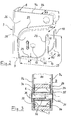
- the in Fig. 2 illustrated, in cross-section U-shaped base body 3 of the support 2 is composed of the two mutually substantially parallel side walls 7a, 7b and a transverse wall or end wall 8 together.
- the side walls 7a, 7b are provided with in the direction of travel and substantially horizontally extending openings 15 for passing the bolt 6.
- the end wall 8 of the support base 3 faces forward, ie in the direction of travel.
- the body is, as long as it is not welded to the chassis, open backwards, downwards and upwards.
- the side walls 7a and 7b extend to a freely tapered lower edge 9 and a likewise free expiring rear edge 10, the transition 13 is here rechfiivinklig-angular, but may also be rounded or deviating from a right angle, angled transition can be ,
- the base body 3 is in one piece by all its walls, so the side walls 7a, 7b and the front end wall 8, sections of the same sheet metal strip.
- This sheet metal strip of eg steel sheet of 6 mm material thickness is used in a cold forming process, eg in a punching or punching bending process to the in Fig. 2 remodeled reproduced sheet metal part. This happens in a single manufacturing step.
- the side walls 7a and 7b extend, starting from the end wall 8, in base regions 26 at a mutual distance A3 to the rear.
- This distance A3 is made as low as possible to allow the connectability of the upper edge 4 of the support to a main longitudinal member of the vehicle chassis, which is also made as narrow as possible.
- side wall regions 28, which are located around the opening 15, are widened along transitions 22 to a distance A1 that is greater than the distance A3.
- the sidewall regions 28, which have been widened relative to one another in this way, are widened on further passages 24 to freely tapering wall sections 30 with a mutual distance A2, which is once again greater than the distance A1.
- the freely extending wall portions 30 each extend over an edge portion 29 of the side wall of a length ranging from the lower edge 9 to the rear edge 10 of the side wall 7a, 7b.
- the distance A between the edges 9, 10 and the first transition 24 is three times the thickness D of the sheet from which the base body 3 is formed.
- the thickness D is 6 mm when using a steel sheet.
- the wall portion 30 extends over about three quarters of the length of the lower edge 9, and at the same time over about two thirds of the height of the rear edge 10th
- the distance A1 of the side wall regions 28 substantially corresponds to the length L of a steel bushing 32 (FIG. Fig. 3
- the length L of the steel bushing 32 is the greatest width of the wishbone assembly to be inserted from below or from behind into the support 2. If, therefore, the wishbone 5 is once positioned between the side walls of the support 2, the loads acting on the wishbone 5 can be transferred directly to the side walls via the steel bushing 32 resting directly on the inside from both side walls 7a, 7b.
- the first transitions 24 however, they extend the distance A1 to the greater distance A2 in the wall sections 30, so that, with sufficient width, they together with the transitions 24 act as a sort of insertion aid in assembly.
- the first transitions 24 are rounded and oblique, ie without edge, formed.
- the first transitions 24 define the wall portion 30.
- the transitions 24 are composed of two rectilinear portions parallel to the lower edge 9 and the rear edge 10, and a central portion of quarter-circle shape connecting them.
- Fig. 3 shows in a vertical section, the support 2, formed by the eye 33 of the axle guide 5 Achslenkerö Anlagen, the bolt 6 and further the steel-rubber bushing 14, the rubber sits in the handle eye 33, and passes through the steel bushing 32 of the bolt. It concerns with Fig. 3 To the assembled state of the axle guide 5 in the support 2, in which the steel bushing 32 via the provided with a nut 31 bolt 6 directly, ie without interposed wear plates, against the side walls 7 a, 7 b is braced. Between the pin 6 and the inner shell of the steel bushing 32 is still a plastic bushing 35 is arranged.
- the two of metal or plastic wear plates 34 have such a large central opening 36 that they surround the steel bushing 32 annular. It has been found that the essential part of the wear caused by friction wear of the support 2 is not in the area of the system of steel bushing 32 inside on the side walls 7a, 7b, but further radially outward in the region of the eye 33 of the axle guide 5 results, and therefore the described positioning of the wear plates 34 is advantageous.
- This positioning of the wear plates 34 also allows the assembly step of the subsequent insertion of the wear plates as in the DE 201 04 753 U1 or the pre-welding of wear plates as in the EP 0 504 593 B1 save. Instead, the wear plates 34 are already placed before the onset of the axle guide 5 with their central openings 36 on the ends of the steel bushing 32, and then introduced together with the wishbone 5 from below or from behind into the support 2.
- the invention is described with reference to an air suspension vehicle axle of a commercial vehicle trailer. It can be used in the same way in other Achsbauart, z. Example, in a vehicle axle, which is supported by leaf springs or leaf spring assemblies relative to the vehicle frame.
Landscapes
- Engineering & Computer Science (AREA)
- Mechanical Engineering (AREA)
- Vehicle Body Suspensions (AREA)
- Axle Suspensions And Sidecars For Cycles (AREA)
- Body Structure For Vehicles (AREA)
Abstract
Description
- Die Erfindung betrifft eine Abstützung zur schwenkbaren Lagerung des Achslenkers einer Fahrzeugachse, mit einem Stützengrundkörper aus zwei über eine in Fahrtrichtung vorne angeordnete Stirnwand miteinander verbundenen Seitenwänden, die jeweils versehen sind mit
- einer Öffnung für einen die Schwenkachse bildenden, quer durch die Seitenwände und den dazwischen einsetzbaren Achslenker hindurchführenden Bolzen,
- einem Randabschnitt, der von dem unteren bis in den rückwärtigen Rand der Seitenwand reicht und als frei auslaufender Wandabschnitt ausgebildet ist.
- Eine Abstützung zur schwenkbaren Lagerung eines Achslenkers mit diesen Merkmalen ist aus der
DE 201 04 753 U1 bekannt. Derartige Lagerungen dienen zur Übertragung von vor allem beim Einfedern des Fahrzeugs aufgenommenen Belastungen von dem Achslenker über den Stützengrundkörper auf den Fahrzeugrahmen. Der von einer Stahlbuchse oder einer Stahl-Gummi-Buchse umgebene Bolzen dient in der Regel nur der benötigten axialen Einspannung des Achslenkers. Der Bolzen selbst bleibt von den vom Achslenker über die Stahlbuchse auf die Stütze übertragenen Kräften weitgehend oder vollständig entlastet. Damit sich bei der Achsenmontage der Achslenker leichter zwischen den beiden Seitenwänden des Stützengrundkörpers einfügt, ist das Montagemaß zwischen den Seitenwänden ausreichend groß bemessen. In die so nach dem Einsetzen des Achslenkers verbleibenden Spalte werden nachträglich, also in einem zusätzlichen Montageschritt, jeweils Verschleißbleche eingesetzt. Diese werden eingesetzt in die sich ergebenden vertikalen Spalte zwischen dem Achslenker bzw. dessen Auge, und den Seitenwänden der Stütze durch Hineinschieben von unten und/oder von hinten her. Nachteilig ist ferner, dass, um das Hindurchführen des Bolzens durch eine ungenaue Positionierung der Verschleißscheiben nicht zu beeinträchtigen, eine Reihe von konstruktiven Maßnahmen sowohl an den Verschleißscheiben, als auch an der Stütze selber notwendig werden. - Bei einer Abstützung nach der
EP 0 504 593 B1 sind innen an den Seitenwänden jeweils Verschleißbleche angeschweißt. Diese Bauweise führt einerseits zu einem erhöhten Fertigungsaufwand durch das zusätzlich erforderliche Einschweißen. Zum anderen besteht die Gefahr, dass beim Absenken der bereits unter dem Fahrzeugchassis befestigten Stütze auf den Achslenker der Fahrzeugachse das Achslenkerauge beim Einfahren in den Stützengrundkörper an den dort bereits befestigten Schweißblechen hängenbleibt, insbesondere wenn diese mit unsauber ausgeführten, hervorstehenden Schweißnähten befestigt sind. Selbst bei nur partieller Verschweißung der Schweißbleche bleibt ein stufiger und damit kantiger Übergang, welcher das hinein Bewegen des Achslenkerauges behindert. - Der Erfindung liegt die Aufgabe zugrunde, durch konstruktive Maßnahmen an der der schwenkbaren Lagerung des Achslenkers dienenden Abstützung eine erleichterte Montage des Achslenkers zu erreichen.
- Zur Lösung dieser Aufgabe wird bei einer Abstützung mit den eingangs angegebenen Merkmalen vorgeschlagen, dass zumindest im Bereich der Randabschnitte die Wandabschnitte zu einem gegenseitigen Abstand aufgeweitet sind, der größer als der Abstand der Seitenwandbereiche um die Öffnungen herum ist.
- Bei der solcherart ausgebildeten Stütze ist das Einsetzen des Achslenkers in den Stützengrundkörper wegen den größeren Abstandes der Seitenwände im Bereich der Wandabschnitte, und wegen des sich dadurch ergebenden größeren Spiels zu Beginn des Einsetzvorgangs deutlich erleichtert. Dies ist vor allem deshalb von Vorteil, da das Einfügen des relativ schweren Achslenkers zwischen die Seitenwände des vorzugsweise als Blechformteil ausgebildeten Stützengrundkörpers häufig ohne maschinelle Hilfe erfolgt und somit nicht so präzise ausgeführt werden kann. Die größere Breitendimensionierung des Stützengrundkörpers zumindest in den "Einfädelungsbereichen" verringert die Gefahr des Anschlagens des Achslenkers gegen die bzw. des Verkantens zwischen den beiden Seitenwänden der Stütze oder dort bereits angebrachten Verschleißblechen.
- Es ist nicht erforderlich, das innere Montagemaß der Stütze im Bereich um die Bolzendurchführung mit Übermaß auszuführen und die so entstehenden vertikalen Spalte z.B. durch nachträgliches Hineinschieben von Verschleißscheiben zu schließen.
- Erreicht wird insgesamt eine einfachere und somit preiswerte Fertigung frei von zusätzlichen Montageschritten beim Aufsetzen der zumeist bereits unter dem Fahrzeugchassis befestigten Stütze auf den Achslenker.
- Zu diesen Erleichterungen trägt in einer bevorzugten Ausgestaltung weiter bei, dass ein Übergang zwischen den Seitenwandbereichen mit dem kleineren Abstand zu den Wandabschnitten mit dem größeren Abstand ausschließlich abgerundet und kantenlos gestaltet ist. Dieser Übergang stellt ansonsten durch den verringerten gegenseitigen Abstand der Seitenwände eine Verengung, und somit eine potenzielle Gefahrenquelle für ein Verkanten bzw. ein Hängenbleiben des Achslenkers an den Seitenwänden beim Einfügen dar. Durch die abgerundeten und kantenlosen Seitenwände in diesem Bereich wirkt der Übergang durch seine gewissermaßen "weiche" Ausformung wie eine Zentrierhilfe, an der der Achslenker in Richtung zu dem Wandbereich mit verringertem Abstand entlang gleiten kann.
- Mit einer Ausgestaltung wird vorgeschlagen, dass die frei auslaufenden Wandabschnitte ausschließlich an Seitenwandbereiche mit dem kleineren Abstand angrenzen. Der Abstand dieser Seitenwandbereiche ist gleich der Länge einer den Bolzen umgebenden Stahlbuchse des Achslenkers.
- In einer weiteren Ausgestaltung der Abstützung wird vorgeschlagen, dass die Blechdicke der Seitenwandbereiche und den Wandabschnitten gleich stark ist. Die Verformung der Seitenwände erfolgt durch partielles Tiefziehen des Blechs, vorzugsweise Stahlblechs, aus dem der Grundkörper der Stütze besteht.
- Weitere Einzelheiten und Vorteile ergeben sich aus der nachfolgenden Beschreibung, in der auf die zugehörigen Zeichnungen Bezug genommen wird. Darin zeigen:
- Fig. 1
- in perspektivischer Darstellung eine Abstützung für einen Achslenker einschließlich des Achslenkers einer luftgefederten Fahrzeugachse zum Einsatz in einem Nutzfahrzeuganhänger;
- Fig. 2
- in perspektivischer Darstellung ausschließlich den einstückigen Grundkörper der Stütze, und
- Fig. 3
- einen Teilschnitt gemäß der
Fig. 1 eingezeichneten Schnittebene III - III; - Unter dem Fahrzeugrahmen eines Lkw-Anhängers oder -Aufliegers sind links und rechts jeweils Stützen 2 befestigt, vorzugsweise durch Verschweißen ihres oberen Randes 4 mit der Unterseite der Längsträger des Fahrzeugrahmens. In jeder Abstützung ist, schwenkbar um jeweils einen Gewindebolzen 6, ein Achslenker 5 für die Fahrzeugachse schwenkbar gelagert.
- Jeder Achslenker ist als ein Gießteil aus Stahlguss oder Leichtmetallguss ausgebildet. Das vordere Ende jedes Achslenkers 5 ist als Auge gestaltet, in dem eine Stahl-Gummi-Buchse 14 sitzt. Durch diese sowie durch die Seitenwände 7a, 7b der Stütze 2 hindurch erstreckt sich der Bolzen 6. An den rückwärtigen Enden der Achslenker 5 sind jeweils, was die Zeichnung nicht zeigt, Luftfederbälge einer in üblicher Weise gestalteten Luftfederung befestigt. Üblicherweise stützen sich derartige Luftfederbälge von unten gegen den Fahrzeugrahmen ab.
- Jeder Achslenker 5 ist in einer Achsaufnahme 11 mit dem Achskörper der Fahrzeugachse verbunden. Der Achskörper, vorzugsweise ein Achsrohr, ist von der linken bis zur rechten Fahrzeugseite durchgehend gestaltet und trägt an seinen beiden Enden die Radlagerungen der Fahrzeugräder. Zwischen dem Achslenker 5 und der Stütze 2 befindet sich ein Stoßdämpfer, wozu Stütze und Achslenker mit Aufnahmebuchsen 12 für den Stoßdämpfer versehen sind. Zur Einstellung der Spur und des Vorlaufs der Fahrzeugachse sind die Stützen 2 mit Justiervorrichtungen 20 versehen.
- Der in
Fig. 2 dargestellte, im Querschnitt U-förmig gestaltete Grundkörper 3 der Stütze 2 setzt sich aus den beiden zueinander im Wesentlichen parallelen Seitenwänden 7a, 7b und einer Querwand oder Stirnwand 8 zusammen. Die Seitenwände 7a, 7b sind mit in Fahrtrichtung und im Wesentlichen horizontal verlaufenden Öffnungen 15 zum Hindurchführen des Bolzens 6 versehen. - Die Stirnwand 8 des Stützengrundkörpers 3 weist nach vorne, also in Fahrtrichtung. Der Grundkörper ist, solange er nicht mit dem Chassis verschweißt ist, nach hinten, nach unten und nach oben offen. Die Seitenwände 7a und 7b erstrecken sich bis zu einem frei auslaufenden unteren Rand 9 und einem ebenfalls frei auslaufenden rückwärtigen Rand 10, deren Übergang 13 hier rechfiivinklig-eckig ist, aber auch gerundet sein kann oder ein von einem rechten Winkel abweichender, winkliger Übergang sein kann.
- In fertigungstechnisch vorteilhafter Ausgestaltung ist der Grundkörper 3 einteilig, indem alle seine Wände, also die Seitenwände 7a, 7b und die vordere Stirnwand 8, Abschnitte ein- und desselben Blechstreifens sind. Dieser Blechstreifen aus z.B. Stahlblech von 6 mm Materialdicke wird in einem Kaltumformprozess, z.B. in einem Stanz- oder Stanz-Biege-Prozess zu dem in
Fig. 2 wiedergegebenen Blechformteil umgestaltet. Dies geschieht in einem einzigen Fertigungsschritt. - Die Seitenwände 7a und 7b erstrecken sich, ausgehend von der Stirnwand 8, in Grundbereichen 26 mit einem gegenseitigen Abstand A3 nach hinten. Dieser Abstand A3 ist möglichst gering ausgeführt, um die Anschließbarkeit des oberen Randes 4 der Stütze an einen Hauptlängsträger des Fahrzeugchassis, welcher ebenfalls möglichst schmal ausgeführt ist, zu ermöglichen. Innerhalb eines Fertigungsschrittes werden hiervon ausgehend Seitenwandbereiche 28, welche sich um die Öffnung 15 herum befinden, entlang von Übergängen 22 auf einen Abstand A1 aufgeweitet, der größer als der Abstand A3 ist.
- Ebenso und im selben Fertigungsschritt werden die derart zueinander aufgeweiteten Seitenwandbereiche 28 an weiteren Übergangen 24 zu frei auslaufenden Wandabschnitten 30 mit einem gegenseitigen Abstand A2 aufgeweitet, der nochmals größer als der Abstand A1 ist. Die frei auslaufenden Wandabschnitte 30 erstrecken sich jeweils über einen Randabschnitt 29 der Seitenwand von einer Länge, die von dem unteren Rand 9 bis in den rückwärtigen Rand 10 der Seitenwand 7a , 7b reicht.
- Der Abstand A zwischen den Rändern 9, 10 und dem ersten Übergang 24 beträgt das Dreifache der Dicke D des Blechs, aus dem der Grundkörper 3 geformt ist. Die Dicke D beträgt bei Verwendung eines Stahlblechs 6 mm.
- Gemäß
Fig. 2 erstreckt sich der Wandabschnitt 30 über etwa drei Viertel der Länge des unteren Randes 9, und zugleich über etwa zwei Drittel der Höhe des rückwärtigen Randes 10. - Der Abstand A1 der Seitenwandbereiche 28 entspricht im Wesentlichen der Länge L einer Stahlbuchse 32 (
Fig. 3 ) der Gummi-Stahl-Buchse 14. Gleichzeitig ist die Länge L der Stahlbuchse 32 die größte Breite der von unten oder von hinten her in die Stütze 2 einzusetzenden Achslenker-Baugruppe. Ist daher der Achslenker 5 einmal zwischen den Seitenwänden der Stütze 2 positioniert, können die auf den Achslenker 5 wirkenden Lasten über die unmittelbar von innen an beiden Seitenwänden 7a, 7b anliegende Stahlbuchse 32 direkt auf die Seitenwände übertragen werden. - Jedoch würde das Einführen des Achslenkers 5 in die Stütze 2 durch die sich entsprechenden Maße A1 und Länge L der Buchse 32 durch fehlendes Spiel zwischen der Buchse 32 und den Seitenwänden 7a, 7b zumindest erschwert. Die ersten Übergänge 24 jedoch weiten den Abstand A1 auf den größeren Abstand A2 in den Wandabschnitten 30 auf, so dass diese, bei ausreichender Breite, zusammen mit den Übergängen 24 als eine Art Einführhilfe beim Zusammenbau fungieren. Dazu sind die ersten Übergänge 24 abgerundet und schräg, d. h. ohne Kante, ausgeformt. Die ersten Übergänge 24 begrenzen den Wandabschnitt 30. Die Übergänge 24 setzen sich aus zwei geradlinigen Abschnitten parallel zu dem unteren Rand 9 und dem rückwärtigen Rand 10 zusammen, sowie einem diese verbindenden Mittelabschnitt von viertelkreisförmiger Gestalt.
-
Fig. 3 zeigt in einem vertikalen Schnitt die Stütze 2, die durch das Auge 33 des Achslenkers 5 gebildete Achslenkeröffnung, den Bolzen 6 sowie ferner die Stahl-Gummi-Buchse 14, deren Gummi in dem Lenkerauge 33 sitzt, und durch deren Stahlbuchse 32 der Bolzen hindurchführt. Es handelt sich beiFig. 3 um dem montierten Zustand des Achslenkers 5 in der Stütze 2, in dem die Stahl buchse 32 über den mit einer Mutter 31 versehenen Schraubbolzen 6 direkt, d. h. ohne dazwischen angeordnete Verschleißscheiben, gegen die Seitenwände 7a, 7b verspannt ist. Zwischen dem Bolzen 6 und dem Innenmantel der Stahlbuchse 32 ist noch eine Kunststoffbuchse 35 angeordnet. - Zwischen dem Achslenker 5 und den Innenseiten der Seitenwände 7a, 7b sind jeweils Verschleißscheiben 34 angeordnet. Die zwei aus Metall oder aus Kunststoff bestehenden Verschleißscheiben 34 weisen eine derart große Mittelöffnung 36 auf, dass sie die Stahlbuchse 32 ringförmig umgeben. Es hat sich herausgestellt, dass der wesentliche Anteil des durch Reibung verursachten Verschleißes der Stütze 2 sich nicht im Bereich der Anlage der Stahlbuchse 32 innen an den Seitenwänden 7a, 7b, sondern weiter radial außen im Bereich des Auges 33 des Achslenkers 5 ergibt, und daher die beschriebene Positionierung der Verschleißscheiben 34 von Vorteil ist.
- Diese Positionierung der Verschleißscheiben 34 ermöglicht es zudem, den Montageschritt des nachträglichen Einfügens der Verschleißscheiben wie bei der
DE 201 04 753 U1 oder des vorab Einschweißens der Verschleißscheiben wie bei derEP 0 504 593 B1 einzusparen. Stattdessen werden die Verschleißscheiben 34 bereits vor dem Einsetzen des Achslenkers 5 mit ihren Mittelöffnungen 36 auf die Enden der Stahlbuchse 32 aufgesetzt, und dann gemeinsam mit dem Achslenker 5 von unten oder von hinten her in die Stütze 2 eingeführt. - Vorstehend ist die Erfindung anhand einer luftgefederten Fahrzeugachse eines Nutzfahrzeuganhängers beschrieben. Sie lässt sich in gleicher Weise auch bei anderen Achsbauarten einsetzen, z. B. bei einer Fahrzeugachse, welche durch Blattfedern oder Blattfederpakete gegenüber dem Fahrzeugrahmen abgestützt ist.
-
- 2
- Stütze
- 3
- Stützengrundkörper
- 4
- Rand
- 5
- Achslenker
- 6
- Bolzen
- 7a
- Seitenwand
- 7b
- Seitenwand
- 8
- Querwand, Stirnwand
- 9
- unterer Rand
- 10
- rückwärtiger Rand
- 11
- Achsaufnahme
- 12
- Aufnahmebuchse für Bolzen des Stoßdämpfers
- 13
- Übergang
- 14
- Stahl-Gummi-Buchse
- 15
- Öffnung
- 20
- Justiervorrichtung
- 22
- zweiter Übergang
- 24
- erster Übergang
- 26
- Grundbereich
- 28
- Seitenwandbereich
- 29
- Randabschnitt
- 30
- Wandabschnitt
- 31
- Mutter
- 32
- Buchse, Stahlbuchse
- 33
- Auge
- 34
- Versschleißscheibe
- 35
- Kunststoffbuchse
- 36
- Mittelöffnung
- A
- Abstand
- A1, A2, A3
- Abstände
- L
- Länge
- D
- Blechdicke
Claims (10)
- Abstützung zur schwenkbaren Lagerung des Achslenkers (5) einer Fahrzeugachse, mit einem Stützengrundkörper (3) aus zwei über eine in Fahrtrichtung vorne angeordnete Stirnwand (8) miteinander verbundenen Seitenwänden (7a, 7b), die jeweils versehen sind mit- einer Öffnung (15) für einen die Schwenkachse bildenden, quer durch die Seitenwände (7a, 7b) und den dazwischen einsetzbaren Achslenker (5) hindurchführenden Bolzen (6),- einem Randabschnitt (29), der von dem unteren Rand (9) bis in den rückwärtigen Rand (10) der Seitenwand (7a, 7b) reicht und als frei auslaufender Wandabschnitt (30) ausgebildet ist,dadurch gekennzeichnet, dass zumindest im Bereich der Randabschnitte (29) die Wandabschnitte (30) zu einem gegenseitigen Abstand (A2) aufgeweitet sind, der größer als der Abstand (A1) der Seitenwandbereiche (28) um die Öffnungen (15) herum ist.
- Abstützung nach Anspruch 1, dadurch gekennzeichnet, dass der Stützengrundkörper (3) als Blechformteil ausgebildet ist.
- Abstützung nach Anspruch 1 oder 2, dadurch gekennzeichnet, dass ein erster Übergang (24) zwischen den Seitenwandbereichen (28) mit dem Abstand (A1) zu den Wandabschnitten (30) mit dem Abstand (A2) ausschließlich abgerundet und kantenlos gestaltet ist.
- Abstützung nach Anspruch 1, 2 oder 3, dadurch gekennzeichnet, dass die Wandabschnitte (30) ausschließlich an die Seitenwandbereiche (28) angrenzen, deren Abstand (A1) der Länge (L) einer den Bolzen (6) umgebenden Stahlbuchse (32) des Achslenkers (5) entspricht.
- Abstützung nach einem der Ansprüche 1 bis 4, dadurch gekennzeichnet, dass die Seitenwände (7a, 7b) jeweils einen Grundbereich (26) mit einem Abstand (A3) aufweisen, welcher in einem zweiten Übergang (22) zu dem Seitenwandbereich (28) aufgeweitet ist.
- Abstützung nach einem der Ansprüche 3 bis 5, dadurch gekennzeichnet, dass jeder Wandabschnitt (30) als eine zusammenhängende Fläche mit zwei linienförmigen und einem viertelkreisförmigen Übergang (24) ausgebildet ist.
- Abstützung nach einem der vorangehenden Ansprüche, dadurch gekennzeichnet, dass die Blechdicke (D) des Stützengrundkörpers (3) in den Seitenwandbereichen (28) und den Wandabschnitten (30) gleich stark ist.
- Abstützung nach einem der Ansprüche 2 bis 7, dadurch gekennzeichnet, dass der Abstand (A) zwischen den Rändern (9, 10) und dem ersten Übergang (24) das Dreifache der Dicke (D) des Blechs beträgt, aus dem der Stützengrundkörper (3) geformt ist.
- Abstützung nach einem der vorangehenden Ansprüche, gekennzeichnet durch eine zwischen dem Bolzen (6) und einem den Bolzen (6) umgebenden Auge (33) des Achslenkers (5) angeordnete Buchse (32), deren Länge (L) im Wesentlichen gleich dem Innenabstand der Seitenwände (7a, 7b) ist.
- Abstützung nach Anspruch 9, dadurch gekennzeichnet, dass zwischen dem Achslenker (5) und der jeweiligen Innenseite der Seitenwände (7a, 7b) jeweils eine Verschleißscheibe (34) angeordnet ist, die mit einer Mittelöffnung (36) die Buchse (32) ringförmig umgibt.
Priority Applications (1)
| Application Number | Priority Date | Filing Date | Title |
|---|---|---|---|
| PL12156620.2T PL2495117T5 (pl) | 2011-03-01 | 2012-02-23 | Podparcie dla uchylnego osadzenia wahacza osi w pojeździe |
Applications Claiming Priority (1)
| Application Number | Priority Date | Filing Date | Title |
|---|---|---|---|
| DE102011001008A DE102011001008A1 (de) | 2011-03-01 | 2011-03-01 | Stütze zur schwenkbaren Lagerung des Achslenkers einer Fahrzeugachse |
Publications (4)
| Publication Number | Publication Date |
|---|---|
| EP2495117A2 true EP2495117A2 (de) | 2012-09-05 |
| EP2495117A3 EP2495117A3 (de) | 2013-07-17 |
| EP2495117B1 EP2495117B1 (de) | 2018-06-27 |
| EP2495117B2 EP2495117B2 (de) | 2024-06-05 |
Family
ID=45656486
Family Applications (1)
| Application Number | Title | Priority Date | Filing Date |
|---|---|---|---|
| EP12156620.2A Active EP2495117B2 (de) | 2011-03-01 | 2012-02-23 | Abstützung zur schwenkbaren Lagerung des Achslenkers einer Fahrzeugachse |
Country Status (5)
| Country | Link |
|---|---|
| EP (1) | EP2495117B2 (de) |
| DE (1) | DE102011001008A1 (de) |
| ES (1) | ES2686926T5 (de) |
| PL (1) | PL2495117T5 (de) |
| TR (1) | TR201810795T4 (de) |
Cited By (4)
| Publication number | Priority date | Publication date | Assignee | Title |
|---|---|---|---|---|
| EP2873596A1 (de) * | 2013-11-18 | 2015-05-20 | BPW Bergische Achsen KG | Achslift für eine Fahrzeugachse |
| DE102015114729A1 (de) * | 2015-09-03 | 2017-03-09 | Saf-Holland Gmbh | Lagerbock |
| DE102016107050A1 (de) * | 2016-04-15 | 2017-10-19 | Saf-Holland Gmbh | Lagerbockeinheit |
| WO2023222540A1 (en) | 2022-05-20 | 2023-11-23 | Vdl Weweler B.V. | Bearing bracket |
Families Citing this family (2)
| Publication number | Priority date | Publication date | Assignee | Title |
|---|---|---|---|---|
| DE102014116077B4 (de) * | 2014-11-04 | 2017-01-19 | Benteler Automobiltechnik Gmbh | Radführungsanordnung für ein Rad eines Fahrzeugs |
| DE102016107852A1 (de) * | 2016-04-28 | 2017-11-02 | Bpw Bergische Achsen Kg | Spureinstellung mit Handhebel |
Citations (8)
| Publication number | Priority date | Publication date | Assignee | Title |
|---|---|---|---|---|
| EP0504593B1 (de) | 1991-03-20 | 1994-07-20 | Bergische Achsenfabrik Fr. Kotz & Söhne | Justiervorrichtung |
| DE20005500U1 (de) | 2000-03-23 | 2000-06-21 | Otto Sauer Achsenfabrik Keilberg, 63856 Bessenbach | Achsanhebevorrichtung |
| DE20104753U1 (de) | 2001-03-20 | 2001-06-07 | BPW Bergische Achsen KG, 51674 Wiehl | Einstellvorrichtung für eine Luft- oder Blattfederachse |
| WO2003062663A1 (en) | 2002-01-16 | 2003-07-31 | The Boler Company | Spacer for suspension arm bushing assemblies |
| DE10310384A1 (de) | 2003-03-07 | 2004-09-16 | Daimlerchrysler Ag | Aufbauseitiger Lagerbock eines Fahrzeugs |
| DE102006044598A1 (de) | 2006-09-19 | 2008-03-27 | Bpw Bergische Achsen Kg | Achslift für luftgefederte Fahrzeugachsen |
| DE102006052218A1 (de) | 2006-11-06 | 2008-05-08 | Saf-Holland Gmbh | Haltevorrichtung für ein Achselement |
| KR20090082823A (ko) | 2008-01-28 | 2009-07-31 | 현대모비스 주식회사 | 서스펜션 결합장치 |
Family Cites Families (8)
| Publication number | Priority date | Publication date | Assignee | Title |
|---|---|---|---|---|
| DE3228051A1 (de) * | 1982-07-27 | 1984-02-09 | Bayerische Motoren Werke AG, 8000 München | Einrichtung zum befestigen zweier bauteile aneinander |
| US5052711A (en) * | 1990-05-18 | 1991-10-01 | A.O. Smith Corporation | Vehicle alignment and verification system |
| WO2000001547A1 (de) * | 1998-07-01 | 2000-01-13 | Bpw Bergische Achsen Kommanditgesellschaft | Stütze zur ableitung der achskräfte einer fahrzeugachse und insbesondere einer lkw-anhängerachse |
| DE20011858U1 (de) * | 2000-07-10 | 2000-09-07 | Feldbinder & Beckmann Fahrzeugbau GmbH & Co KG, 21423 Winsen | Achsbock für Fahrzeuge, insbesondere Kraftfahrzeuge |
| US6945548B2 (en) * | 2001-02-26 | 2005-09-20 | Hendrickson Usa, L.L.C. | Air spring and air spring mounting assembly |
| DE20317350U1 (de) | 2003-11-11 | 2004-02-12 | Trenkamp & Gehle Gmbh | Achsanhebevorrichtung für Nutzfahrzeuge |
| GB0511310D0 (en) * | 2005-06-03 | 2005-07-13 | Meritor Heavy Vehicle Sys Ltd | A suspension trailing arm |
| JP2007137087A (ja) * | 2005-11-14 | 2007-06-07 | Suzuki Motor Corp | 車両のリアサスペンション装置 |
-
2011
- 2011-03-01 DE DE102011001008A patent/DE102011001008A1/de active Pending
-
2012
- 2012-02-23 EP EP12156620.2A patent/EP2495117B2/de active Active
- 2012-02-23 ES ES12156620T patent/ES2686926T5/es active Active
- 2012-02-23 TR TR2018/10795T patent/TR201810795T4/tr unknown
- 2012-02-23 PL PL12156620.2T patent/PL2495117T5/pl unknown
Patent Citations (8)
| Publication number | Priority date | Publication date | Assignee | Title |
|---|---|---|---|---|
| EP0504593B1 (de) | 1991-03-20 | 1994-07-20 | Bergische Achsenfabrik Fr. Kotz & Söhne | Justiervorrichtung |
| DE20005500U1 (de) | 2000-03-23 | 2000-06-21 | Otto Sauer Achsenfabrik Keilberg, 63856 Bessenbach | Achsanhebevorrichtung |
| DE20104753U1 (de) | 2001-03-20 | 2001-06-07 | BPW Bergische Achsen KG, 51674 Wiehl | Einstellvorrichtung für eine Luft- oder Blattfederachse |
| WO2003062663A1 (en) | 2002-01-16 | 2003-07-31 | The Boler Company | Spacer for suspension arm bushing assemblies |
| DE10310384A1 (de) | 2003-03-07 | 2004-09-16 | Daimlerchrysler Ag | Aufbauseitiger Lagerbock eines Fahrzeugs |
| DE102006044598A1 (de) | 2006-09-19 | 2008-03-27 | Bpw Bergische Achsen Kg | Achslift für luftgefederte Fahrzeugachsen |
| DE102006052218A1 (de) | 2006-11-06 | 2008-05-08 | Saf-Holland Gmbh | Haltevorrichtung für ein Achselement |
| KR20090082823A (ko) | 2008-01-28 | 2009-07-31 | 현대모비스 주식회사 | 서스펜션 결합장치 |
Cited By (7)
| Publication number | Priority date | Publication date | Assignee | Title |
|---|---|---|---|---|
| EP2873596A1 (de) * | 2013-11-18 | 2015-05-20 | BPW Bergische Achsen KG | Achslift für eine Fahrzeugachse |
| DE102015114729A1 (de) * | 2015-09-03 | 2017-03-09 | Saf-Holland Gmbh | Lagerbock |
| DE102015114729B4 (de) | 2015-09-03 | 2020-06-10 | Saf-Holland Gmbh | Lagerbock |
| DE102016107050A1 (de) * | 2016-04-15 | 2017-10-19 | Saf-Holland Gmbh | Lagerbockeinheit |
| DE102016107050B4 (de) * | 2016-04-15 | 2020-11-12 | Saf-Holland Gmbh | Lagerbockeinheit |
| WO2023222540A1 (en) | 2022-05-20 | 2023-11-23 | Vdl Weweler B.V. | Bearing bracket |
| NL2031947B1 (en) | 2022-05-20 | 2023-11-27 | Vdl Weweler Bv | Bearing bracket |
Also Published As
| Publication number | Publication date |
|---|---|
| EP2495117B1 (de) | 2018-06-27 |
| DE102011001008A1 (de) | 2012-09-06 |
| PL2495117T3 (pl) | 2018-10-31 |
| EP2495117A3 (de) | 2013-07-17 |
| TR201810795T4 (tr) | 2018-08-27 |
| ES2686926T3 (es) | 2018-10-22 |
| ES2686926T5 (es) | 2024-10-09 |
| PL2495117T5 (pl) | 2024-09-09 |
| EP2495117B2 (de) | 2024-06-05 |
Similar Documents
| Publication | Publication Date | Title |
|---|---|---|
| EP2049284B1 (de) | Achsaggregat | |
| DE102013108695B4 (de) | Hilfsrahmen für eine Kraftfahrzeugachse | |
| EP2607115B1 (de) | Achsaufhängung für eine Fahrzeugachse | |
| EP2495117B1 (de) | Abstützung zur schwenkbaren Lagerung des Achslenkers einer Fahrzeugachse | |
| EP2688792B1 (de) | Achsaufhängung sowie achslift für eine fahrzeugachse | |
| DE102009035219A1 (de) | Rahmenstruktur eines Fahrzeug | |
| DE102015015520A1 (de) | Drehstabfederungsstruktur | |
| DE19905676B4 (de) | Zugdeichsel für Zentralachsanhänger | |
| EP2502809B1 (de) | Anhebevorrichtung für einen Achslenker sowie Achslenker | |
| EP2495116B1 (de) | Stütze zur schwenkbaren Lagerung des Achslenkers einer Fahrzeugachse | |
| EP2772372A1 (de) | Fahrwerk für ein Nutzfahrzeug, Achskörper sowie Verfahren zum Herstellen eines Achskörpers | |
| EP1370432B1 (de) | Achsaggregat | |
| EP2593348B1 (de) | Lenkachse | |
| DE19751217C1 (de) | Hinterer Unterfahrschutz für Nutzfahrzeuge | |
| EP2647512B1 (de) | Achslenker | |
| DE102013112693A1 (de) | Achslift für eine Fahrzeugachse | |
| EP2873596A1 (de) | Achslift für eine Fahrzeugachse | |
| EP2543527A1 (de) | Fahrzeugachslenker sowie Verschlussstopfen zur Verwendung in einem Fahrzeugachslenker | |
| EP2325031B1 (de) | Fahrgestell eines Nutzfahrzeugs mit einem Längsträger und einem Federbock | |
| EP3098093A1 (de) | Zuggabel für ein anhängerfahrzeug | |
| EP3946986B1 (de) | Achseinbindung für eine fahrzeugachse sowie achsplatte hierfür | |
| DE10209109B4 (de) | Fahrzeugachse in der Bauart als Halbachse | |
| WO2015181200A1 (de) | Achsanordnung | |
| DE102017115692A1 (de) | Achslenker sowie Achsaufhängung für eine Fahrzeugachse | |
| DE102019104428A1 (de) | Fahrwerk für ein Nutzfahrzeug sowie Achsschale für ein Fahrwerk |
Legal Events
| Date | Code | Title | Description |
|---|---|---|---|
| PUAI | Public reference made under article 153(3) epc to a published international application that has entered the european phase |
Free format text: ORIGINAL CODE: 0009012 |
|
| AK | Designated contracting states |
Kind code of ref document: A2 Designated state(s): AL AT BE BG CH CY CZ DE DK EE ES FI FR GB GR HR HU IE IS IT LI LT LU LV MC MK MT NL NO PL PT RO RS SE SI SK SM TR |
|
| AX | Request for extension of the european patent |
Extension state: BA ME |
|
| PUAL | Search report despatched |
Free format text: ORIGINAL CODE: 0009013 |
|
| AK | Designated contracting states |
Kind code of ref document: A3 Designated state(s): AL AT BE BG CH CY CZ DE DK EE ES FI FR GB GR HR HU IE IS IT LI LT LU LV MC MK MT NL NO PL PT RO RS SE SI SK SM TR |
|
| AX | Request for extension of the european patent |
Extension state: BA ME |
|
| RIC1 | Information provided on ipc code assigned before grant |
Ipc: B60G 7/02 20060101AFI20130612BHEP |
|
| 17P | Request for examination filed |
Effective date: 20131210 |
|
| RBV | Designated contracting states (corrected) |
Designated state(s): AL AT BE BG CH CY CZ DE DK EE ES FI FR GB GR HR HU IE IS IT LI LT LU LV MC MK MT NL NO PL PT RO RS SE SI SK SM TR |
|
| GRAP | Despatch of communication of intention to grant a patent |
Free format text: ORIGINAL CODE: EPIDOSNIGR1 |
|
| STAA | Information on the status of an ep patent application or granted ep patent |
Free format text: STATUS: GRANT OF PATENT IS INTENDED |
|
| INTG | Intention to grant announced |
Effective date: 20180130 |
|
| GRAS | Grant fee paid |
Free format text: ORIGINAL CODE: EPIDOSNIGR3 |
|
| GRAA | (expected) grant |
Free format text: ORIGINAL CODE: 0009210 |
|
| STAA | Information on the status of an ep patent application or granted ep patent |
Free format text: STATUS: THE PATENT HAS BEEN GRANTED |
|
| AK | Designated contracting states |
Kind code of ref document: B1 Designated state(s): AL AT BE BG CH CY CZ DE DK EE ES FI FR GB GR HR HU IE IS IT LI LT LU LV MC MK MT NL NO PL PT RO RS SE SI SK SM TR |
|
| REG | Reference to a national code |
Ref country code: GB Ref legal event code: FG4D Free format text: NOT ENGLISH |
|
| REG | Reference to a national code |
Ref country code: AT Ref legal event code: REF Ref document number: 1011980 Country of ref document: AT Kind code of ref document: T Effective date: 20180715 |
|
| REG | Reference to a national code |
Ref country code: DE Ref legal event code: R096 Ref document number: 502012012926 Country of ref document: DE |
|
| REG | Reference to a national code |
Ref country code: IE Ref legal event code: FG4D Free format text: LANGUAGE OF EP DOCUMENT: GERMAN |
|
| REG | Reference to a national code |
Ref country code: DE Ref legal event code: R082 Ref document number: 502012012926 Country of ref document: DE Representative=s name: DREISS PATENTANWAELTE PARTG MBB, DE Ref country code: DE Ref legal event code: R082 Ref document number: 502012012926 Country of ref document: DE Representative=s name: JANKE SCHOLL PATENTANWAELTE PARTG MBB, DE Ref country code: DE Ref legal event code: R082 Ref document number: 502012012926 Country of ref document: DE Representative=s name: CHRISTOPHERSEN PATENTANWAELTE, DE Ref country code: DE Ref legal event code: R082 Ref document number: 502012012926 Country of ref document: DE Representative=s name: CHRISTOPHERSEN & PARTNER PARTNERSCHAFT MBB PAT, DE Ref country code: DE Ref legal event code: R082 Ref document number: 502012012926 Country of ref document: DE Representative=s name: BUNGARTZ CHRISTOPHERSEN PARTNERSCHAFT MBB PATE, DE |
|
| REG | Reference to a national code |
Ref country code: NL Ref legal event code: FP |
|
| REG | Reference to a national code |
Ref country code: ES Ref legal event code: FG2A Ref document number: 2686926 Country of ref document: ES Kind code of ref document: T3 Effective date: 20181022 |
|
| PG25 | Lapsed in a contracting state [announced via postgrant information from national office to epo] |
Ref country code: BG Free format text: LAPSE BECAUSE OF FAILURE TO SUBMIT A TRANSLATION OF THE DESCRIPTION OR TO PAY THE FEE WITHIN THE PRESCRIBED TIME-LIMIT Effective date: 20180927 Ref country code: SE Free format text: LAPSE BECAUSE OF FAILURE TO SUBMIT A TRANSLATION OF THE DESCRIPTION OR TO PAY THE FEE WITHIN THE PRESCRIBED TIME-LIMIT Effective date: 20180627 Ref country code: NO Free format text: LAPSE BECAUSE OF FAILURE TO SUBMIT A TRANSLATION OF THE DESCRIPTION OR TO PAY THE FEE WITHIN THE PRESCRIBED TIME-LIMIT Effective date: 20180927 Ref country code: FI Free format text: LAPSE BECAUSE OF FAILURE TO SUBMIT A TRANSLATION OF THE DESCRIPTION OR TO PAY THE FEE WITHIN THE PRESCRIBED TIME-LIMIT Effective date: 20180627 Ref country code: LT Free format text: LAPSE BECAUSE OF FAILURE TO SUBMIT A TRANSLATION OF THE DESCRIPTION OR TO PAY THE FEE WITHIN THE PRESCRIBED TIME-LIMIT Effective date: 20180627 |
|
| REG | Reference to a national code |
Ref country code: LT Ref legal event code: MG4D |
|
| PG25 | Lapsed in a contracting state [announced via postgrant information from national office to epo] |
Ref country code: HR Free format text: LAPSE BECAUSE OF FAILURE TO SUBMIT A TRANSLATION OF THE DESCRIPTION OR TO PAY THE FEE WITHIN THE PRESCRIBED TIME-LIMIT Effective date: 20180627 Ref country code: GR Free format text: LAPSE BECAUSE OF FAILURE TO SUBMIT A TRANSLATION OF THE DESCRIPTION OR TO PAY THE FEE WITHIN THE PRESCRIBED TIME-LIMIT Effective date: 20180928 Ref country code: LV Free format text: LAPSE BECAUSE OF FAILURE TO SUBMIT A TRANSLATION OF THE DESCRIPTION OR TO PAY THE FEE WITHIN THE PRESCRIBED TIME-LIMIT Effective date: 20180627 Ref country code: RS Free format text: LAPSE BECAUSE OF FAILURE TO SUBMIT A TRANSLATION OF THE DESCRIPTION OR TO PAY THE FEE WITHIN THE PRESCRIBED TIME-LIMIT Effective date: 20180627 |
|
| PG25 | Lapsed in a contracting state [announced via postgrant information from national office to epo] |
Ref country code: SK Free format text: LAPSE BECAUSE OF FAILURE TO SUBMIT A TRANSLATION OF THE DESCRIPTION OR TO PAY THE FEE WITHIN THE PRESCRIBED TIME-LIMIT Effective date: 20180627 Ref country code: RO Free format text: LAPSE BECAUSE OF FAILURE TO SUBMIT A TRANSLATION OF THE DESCRIPTION OR TO PAY THE FEE WITHIN THE PRESCRIBED TIME-LIMIT Effective date: 20180627 Ref country code: CZ Free format text: LAPSE BECAUSE OF FAILURE TO SUBMIT A TRANSLATION OF THE DESCRIPTION OR TO PAY THE FEE WITHIN THE PRESCRIBED TIME-LIMIT Effective date: 20180627 Ref country code: EE Free format text: LAPSE BECAUSE OF FAILURE TO SUBMIT A TRANSLATION OF THE DESCRIPTION OR TO PAY THE FEE WITHIN THE PRESCRIBED TIME-LIMIT Effective date: 20180627 Ref country code: IS Free format text: LAPSE BECAUSE OF FAILURE TO SUBMIT A TRANSLATION OF THE DESCRIPTION OR TO PAY THE FEE WITHIN THE PRESCRIBED TIME-LIMIT Effective date: 20181027 |
|
| PG25 | Lapsed in a contracting state [announced via postgrant information from national office to epo] |
Ref country code: SM Free format text: LAPSE BECAUSE OF FAILURE TO SUBMIT A TRANSLATION OF THE DESCRIPTION OR TO PAY THE FEE WITHIN THE PRESCRIBED TIME-LIMIT Effective date: 20180627 |
|
| REG | Reference to a national code |
Ref country code: DE Ref legal event code: R026 Ref document number: 502012012926 Country of ref document: DE |
|
| PLBI | Opposition filed |
Free format text: ORIGINAL CODE: 0009260 |
|
| PLAX | Notice of opposition and request to file observation + time limit sent |
Free format text: ORIGINAL CODE: EPIDOSNOBS2 |
|
| 26 | Opposition filed |
Opponent name: SAF-HOLLAND GMBH Effective date: 20190326 |
|
| PG25 | Lapsed in a contracting state [announced via postgrant information from national office to epo] |
Ref country code: DK Free format text: LAPSE BECAUSE OF FAILURE TO SUBMIT A TRANSLATION OF THE DESCRIPTION OR TO PAY THE FEE WITHIN THE PRESCRIBED TIME-LIMIT Effective date: 20180627 |
|
| PLBB | Reply of patent proprietor to notice(s) of opposition received |
Free format text: ORIGINAL CODE: EPIDOSNOBS3 |
|
| PG25 | Lapsed in a contracting state [announced via postgrant information from national office to epo] |
Ref country code: SI Free format text: LAPSE BECAUSE OF FAILURE TO SUBMIT A TRANSLATION OF THE DESCRIPTION OR TO PAY THE FEE WITHIN THE PRESCRIBED TIME-LIMIT Effective date: 20180627 |
|
| REG | Reference to a national code |
Ref country code: CH Ref legal event code: PL |
|
| PG25 | Lapsed in a contracting state [announced via postgrant information from national office to epo] |
Ref country code: MC Free format text: LAPSE BECAUSE OF FAILURE TO SUBMIT A TRANSLATION OF THE DESCRIPTION OR TO PAY THE FEE WITHIN THE PRESCRIBED TIME-LIMIT Effective date: 20180627 Ref country code: LU Free format text: LAPSE BECAUSE OF NON-PAYMENT OF DUE FEES Effective date: 20190223 |
|
| REG | Reference to a national code |
Ref country code: BE Ref legal event code: MM Effective date: 20190228 |
|
| REG | Reference to a national code |
Ref country code: IE Ref legal event code: MM4A |
|
| PG25 | Lapsed in a contracting state [announced via postgrant information from national office to epo] |
Ref country code: AL Free format text: LAPSE BECAUSE OF FAILURE TO SUBMIT A TRANSLATION OF THE DESCRIPTION OR TO PAY THE FEE WITHIN THE PRESCRIBED TIME-LIMIT Effective date: 20180627 |
|
| PG25 | Lapsed in a contracting state [announced via postgrant information from national office to epo] |
Ref country code: LI Free format text: LAPSE BECAUSE OF NON-PAYMENT OF DUE FEES Effective date: 20190228 Ref country code: CH Free format text: LAPSE BECAUSE OF NON-PAYMENT OF DUE FEES Effective date: 20190228 |
|
| PG25 | Lapsed in a contracting state [announced via postgrant information from national office to epo] |
Ref country code: IE Free format text: LAPSE BECAUSE OF NON-PAYMENT OF DUE FEES Effective date: 20190223 |
|
| PG25 | Lapsed in a contracting state [announced via postgrant information from national office to epo] |
Ref country code: BE Free format text: LAPSE BECAUSE OF NON-PAYMENT OF DUE FEES Effective date: 20190228 |
|
| REG | Reference to a national code |
Ref country code: AT Ref legal event code: MM01 Ref document number: 1011980 Country of ref document: AT Kind code of ref document: T Effective date: 20190223 |
|
| PG25 | Lapsed in a contracting state [announced via postgrant information from national office to epo] |
Ref country code: AT Free format text: LAPSE BECAUSE OF NON-PAYMENT OF DUE FEES Effective date: 20190223 |
|
| PG25 | Lapsed in a contracting state [announced via postgrant information from national office to epo] |
Ref country code: PT Free format text: LAPSE BECAUSE OF FAILURE TO SUBMIT A TRANSLATION OF THE DESCRIPTION OR TO PAY THE FEE WITHIN THE PRESCRIBED TIME-LIMIT Effective date: 20181029 Ref country code: MT Free format text: LAPSE BECAUSE OF FAILURE TO SUBMIT A TRANSLATION OF THE DESCRIPTION OR TO PAY THE FEE WITHIN THE PRESCRIBED TIME-LIMIT Effective date: 20180627 |
|
| PG25 | Lapsed in a contracting state [announced via postgrant information from national office to epo] |
Ref country code: CY Free format text: LAPSE BECAUSE OF FAILURE TO SUBMIT A TRANSLATION OF THE DESCRIPTION OR TO PAY THE FEE WITHIN THE PRESCRIBED TIME-LIMIT Effective date: 20180627 |
|
| PG25 | Lapsed in a contracting state [announced via postgrant information from national office to epo] |
Ref country code: HU Free format text: LAPSE BECAUSE OF FAILURE TO SUBMIT A TRANSLATION OF THE DESCRIPTION OR TO PAY THE FEE WITHIN THE PRESCRIBED TIME-LIMIT; INVALID AB INITIO Effective date: 20120223 |
|
| APBM | Appeal reference recorded |
Free format text: ORIGINAL CODE: EPIDOSNREFNO |
|
| APBP | Date of receipt of notice of appeal recorded |
Free format text: ORIGINAL CODE: EPIDOSNNOA2O |
|
| APAH | Appeal reference modified |
Free format text: ORIGINAL CODE: EPIDOSCREFNO |
|
| APBM | Appeal reference recorded |
Free format text: ORIGINAL CODE: EPIDOSNREFNO |
|
| APBP | Date of receipt of notice of appeal recorded |
Free format text: ORIGINAL CODE: EPIDOSNNOA2O |
|
| APBQ | Date of receipt of statement of grounds of appeal recorded |
Free format text: ORIGINAL CODE: EPIDOSNNOA3O |
|
| APBQ | Date of receipt of statement of grounds of appeal recorded |
Free format text: ORIGINAL CODE: EPIDOSNNOA3O |
|
| REG | Reference to a national code |
Ref country code: DE Ref legal event code: R082 Ref document number: 502012012926 Country of ref document: DE Representative=s name: DREISS PATENTANWAELTE PARTG MBB, DE Ref country code: DE Ref legal event code: R082 Ref document number: 502012012926 Country of ref document: DE Representative=s name: JANKE SCHOLL PATENTANWAELTE PARTG MBB, DE |
|
| PG25 | Lapsed in a contracting state [announced via postgrant information from national office to epo] |
Ref country code: MK Free format text: LAPSE BECAUSE OF FAILURE TO SUBMIT A TRANSLATION OF THE DESCRIPTION OR TO PAY THE FEE WITHIN THE PRESCRIBED TIME-LIMIT Effective date: 20180627 |
|
| REG | Reference to a national code |
Ref country code: DE Ref legal event code: R082 Ref document number: 502012012926 Country of ref document: DE Representative=s name: DREISS PATENTANWAELTE PARTG MBB, DE |
|
| P01 | Opt-out of the competence of the unified patent court (upc) registered |
Effective date: 20230508 |
|
| APBU | Appeal procedure closed |
Free format text: ORIGINAL CODE: EPIDOSNNOA9O |
|
| PUAH | Patent maintained in amended form |
Free format text: ORIGINAL CODE: 0009272 |
|
| STAA | Information on the status of an ep patent application or granted ep patent |
Free format text: STATUS: PATENT MAINTAINED AS AMENDED |
|
| 27A | Patent maintained in amended form |
Effective date: 20240605 |
|
| AK | Designated contracting states |
Kind code of ref document: B2 Designated state(s): AL AT BE BG CH CY CZ DE DK EE ES FI FR GB GR HR HU IE IS IT LI LT LU LV MC MK MT NL NO PL PT RO RS SE SI SK SM TR |
|
| REG | Reference to a national code |
Ref country code: DE Ref legal event code: R102 Ref document number: 502012012926 Country of ref document: DE |
|
| REG | Reference to a national code |
Ref country code: NL Ref legal event code: FP |
|
| REG | Reference to a national code |
Ref country code: ES Ref legal event code: DC2A Ref document number: 2686926 Country of ref document: ES Kind code of ref document: T5 Effective date: 20241009 |
|
| PGFP | Annual fee paid to national office [announced via postgrant information from national office to epo] |
Ref country code: NL Payment date: 20250220 Year of fee payment: 14 |
|
| PGFP | Annual fee paid to national office [announced via postgrant information from national office to epo] |
Ref country code: ES Payment date: 20250318 Year of fee payment: 14 |
|
| PGFP | Annual fee paid to national office [announced via postgrant information from national office to epo] |
Ref country code: FR Payment date: 20250220 Year of fee payment: 14 Ref country code: PL Payment date: 20250207 Year of fee payment: 14 |
|
| PGFP | Annual fee paid to national office [announced via postgrant information from national office to epo] |
Ref country code: IT Payment date: 20250228 Year of fee payment: 14 Ref country code: GB Payment date: 20250218 Year of fee payment: 14 |
|
| PGFP | Annual fee paid to national office [announced via postgrant information from national office to epo] |
Ref country code: TR Payment date: 20250213 Year of fee payment: 14 |
|
| PGFP | Annual fee paid to national office [announced via postgrant information from national office to epo] |
Ref country code: DE Payment date: 20250415 Year of fee payment: 14 |