EP2495080B1 - Cutting tool with blade made from fine-crystalline diamond - Google Patents
Cutting tool with blade made from fine-crystalline diamond Download PDFInfo
- Publication number
- EP2495080B1 EP2495080B1 EP20110001693 EP11001693A EP2495080B1 EP 2495080 B1 EP2495080 B1 EP 2495080B1 EP 20110001693 EP20110001693 EP 20110001693 EP 11001693 A EP11001693 A EP 11001693A EP 2495080 B1 EP2495080 B1 EP 2495080B1
- Authority
- EP
- European Patent Office
- Prior art keywords
- layer
- cutting tool
- crystalline diamond
- cutting edge
- fine crystalline
- Prior art date
- Legal status (The legal status is an assumption and is not a legal conclusion. Google has not performed a legal analysis and makes no representation as to the accuracy of the status listed.)
- Active
Links
- 229910003460 diamond Inorganic materials 0.000 title claims description 151
- 239000010432 diamond Substances 0.000 title claims description 151
- 238000005520 cutting process Methods 0.000 title claims description 143
- 239000010410 layer Substances 0.000 claims description 154
- 239000011162 core material Substances 0.000 claims description 47
- 239000000463 material Substances 0.000 claims description 22
- OKTJSMMVPCPJKN-UHFFFAOYSA-N Carbon Chemical compound [C] OKTJSMMVPCPJKN-UHFFFAOYSA-N 0.000 claims description 19
- 229910052799 carbon Inorganic materials 0.000 claims description 14
- 239000010936 titanium Substances 0.000 claims description 14
- 229910052719 titanium Inorganic materials 0.000 claims description 14
- 229910052721 tungsten Inorganic materials 0.000 claims description 13
- 229910052751 metal Inorganic materials 0.000 claims description 12
- 239000002184 metal Substances 0.000 claims description 12
- 239000012791 sliding layer Substances 0.000 claims description 12
- BASFCYQUMIYNBI-UHFFFAOYSA-N platinum Chemical compound [Pt] BASFCYQUMIYNBI-UHFFFAOYSA-N 0.000 claims description 11
- PXHVJJICTQNCMI-UHFFFAOYSA-N Nickel Chemical compound [Ni] PXHVJJICTQNCMI-UHFFFAOYSA-N 0.000 claims description 10
- 150000002739 metals Chemical class 0.000 claims description 10
- 239000010937 tungsten Substances 0.000 claims description 10
- -1 for example Chemical class 0.000 claims description 8
- 239000002245 particle Substances 0.000 claims description 8
- 229910052697 platinum Inorganic materials 0.000 claims description 7
- WFKWXMTUELFFGS-UHFFFAOYSA-N tungsten Chemical compound [W] WFKWXMTUELFFGS-UHFFFAOYSA-N 0.000 claims description 7
- IJGRMHOSHXDMSA-UHFFFAOYSA-N Atomic nitrogen Chemical compound N#N IJGRMHOSHXDMSA-UHFFFAOYSA-N 0.000 claims description 6
- XEEYBQQBJWHFJM-UHFFFAOYSA-N Iron Chemical compound [Fe] XEEYBQQBJWHFJM-UHFFFAOYSA-N 0.000 claims description 6
- XUIMIQQOPSSXEZ-UHFFFAOYSA-N Silicon Chemical compound [Si] XUIMIQQOPSSXEZ-UHFFFAOYSA-N 0.000 claims description 6
- RTAQQCXQSZGOHL-UHFFFAOYSA-N Titanium Chemical compound [Ti] RTAQQCXQSZGOHL-UHFFFAOYSA-N 0.000 claims description 6
- 229910052804 chromium Inorganic materials 0.000 claims description 6
- 239000011651 chromium Substances 0.000 claims description 6
- 229910052710 silicon Inorganic materials 0.000 claims description 6
- 239000010703 silicon Substances 0.000 claims description 6
- 229910052581 Si3N4 Inorganic materials 0.000 claims description 5
- 229910000831 Steel Inorganic materials 0.000 claims description 5
- 229910010293 ceramic material Inorganic materials 0.000 claims description 5
- 239000010439 graphite Substances 0.000 claims description 5
- 229910002804 graphite Inorganic materials 0.000 claims description 5
- 229910052759 nickel Inorganic materials 0.000 claims description 5
- 229910010271 silicon carbide Inorganic materials 0.000 claims description 5
- HBMJWWWQQXIZIP-UHFFFAOYSA-N silicon carbide Chemical compound [Si+]#[C-] HBMJWWWQQXIZIP-UHFFFAOYSA-N 0.000 claims description 5
- HQVNEWCFYHHQES-UHFFFAOYSA-N silicon nitride Chemical compound N12[Si]34N5[Si]62N3[Si]51N64 HQVNEWCFYHHQES-UHFFFAOYSA-N 0.000 claims description 5
- 239000010959 steel Substances 0.000 claims description 5
- VYZAMTAEIAYCRO-UHFFFAOYSA-N Chromium Chemical compound [Cr] VYZAMTAEIAYCRO-UHFFFAOYSA-N 0.000 claims description 4
- 229920000642 polymer Polymers 0.000 claims description 4
- 239000004810 polytetrafluoroethylene Substances 0.000 claims description 4
- 229920001343 polytetrafluoroethylene Polymers 0.000 claims description 4
- QIJNJJZPYXGIQM-UHFFFAOYSA-N 1lambda4,2lambda4-dimolybdacyclopropa-1,2,3-triene Chemical compound [Mo]=C=[Mo] QIJNJJZPYXGIQM-UHFFFAOYSA-N 0.000 claims description 3
- 229910052582 BN Inorganic materials 0.000 claims description 3
- ZOXJGFHDIHLPTG-UHFFFAOYSA-N Boron Chemical compound [B] ZOXJGFHDIHLPTG-UHFFFAOYSA-N 0.000 claims description 3
- PZNSFCLAULLKQX-UHFFFAOYSA-N Boron nitride Chemical compound N#B PZNSFCLAULLKQX-UHFFFAOYSA-N 0.000 claims description 3
- 229910039444 MoC Inorganic materials 0.000 claims description 3
- ZOKXTWBITQBERF-UHFFFAOYSA-N Molybdenum Chemical compound [Mo] ZOKXTWBITQBERF-UHFFFAOYSA-N 0.000 claims description 3
- 229910010037 TiAlN Inorganic materials 0.000 claims description 3
- 229910052796 boron Inorganic materials 0.000 claims description 3
- 239000000919 ceramic Substances 0.000 claims description 3
- 239000010941 cobalt Substances 0.000 claims description 3
- 229910017052 cobalt Inorganic materials 0.000 claims description 3
- GUTLYIVDDKVIGB-UHFFFAOYSA-N cobalt atom Chemical compound [Co] GUTLYIVDDKVIGB-UHFFFAOYSA-N 0.000 claims description 3
- 239000002131 composite material Substances 0.000 claims description 3
- 229910052732 germanium Inorganic materials 0.000 claims description 3
- GNPVGFCGXDBREM-UHFFFAOYSA-N germanium atom Chemical compound [Ge] GNPVGFCGXDBREM-UHFFFAOYSA-N 0.000 claims description 3
- 239000011521 glass Substances 0.000 claims description 3
- 239000002241 glass-ceramic Substances 0.000 claims description 3
- 229910052742 iron Inorganic materials 0.000 claims description 3
- 239000011159 matrix material Substances 0.000 claims description 3
- NFFIWVVINABMKP-UHFFFAOYSA-N methylidynetantalum Chemical compound [Ta]#C NFFIWVVINABMKP-UHFFFAOYSA-N 0.000 claims description 3
- 229910052750 molybdenum Inorganic materials 0.000 claims description 3
- 239000011733 molybdenum Substances 0.000 claims description 3
- 229910052758 niobium Inorganic materials 0.000 claims description 3
- 239000010955 niobium Substances 0.000 claims description 3
- GUCVJGMIXFAOAE-UHFFFAOYSA-N niobium atom Chemical compound [Nb] GUCVJGMIXFAOAE-UHFFFAOYSA-N 0.000 claims description 3
- 229910052757 nitrogen Inorganic materials 0.000 claims description 3
- 239000010980 sapphire Substances 0.000 claims description 3
- 229910052594 sapphire Inorganic materials 0.000 claims description 3
- 230000003746 surface roughness Effects 0.000 claims description 3
- 229910003468 tantalcarbide Inorganic materials 0.000 claims description 3
- 229910052715 tantalum Inorganic materials 0.000 claims description 3
- GUVRBAGPIYLISA-UHFFFAOYSA-N tantalum atom Chemical compound [Ta] GUVRBAGPIYLISA-UHFFFAOYSA-N 0.000 claims description 3
- UONOETXJSWQNOL-UHFFFAOYSA-N tungsten carbide Chemical compound [W+]#[C-] UONOETXJSWQNOL-UHFFFAOYSA-N 0.000 claims description 3
- 229910052720 vanadium Inorganic materials 0.000 claims description 3
- LEONUFNNVUYDNQ-UHFFFAOYSA-N vanadium atom Chemical compound [V] LEONUFNNVUYDNQ-UHFFFAOYSA-N 0.000 claims description 3
- 230000001737 promoting effect Effects 0.000 claims 2
- QYEXBYZXHDUPRC-UHFFFAOYSA-N B#[Ti]#B Chemical compound B#[Ti]#B QYEXBYZXHDUPRC-UHFFFAOYSA-N 0.000 claims 1
- 229910033181 TiB2 Inorganic materials 0.000 claims 1
- NRTOMJZYCJJWKI-UHFFFAOYSA-N Titanium nitride Chemical compound [Ti]#N NRTOMJZYCJJWKI-UHFFFAOYSA-N 0.000 claims 1
- ORILYTVJVMAKLC-UHFFFAOYSA-N adamantane Chemical compound C1C(C2)CC3CC1CC2C3 ORILYTVJVMAKLC-UHFFFAOYSA-N 0.000 claims 1
- 229910001573 adamantine Inorganic materials 0.000 claims 1
- PEUPIGGLJVUNEU-UHFFFAOYSA-N nickel silicon Chemical compound [Si].[Ni] PEUPIGGLJVUNEU-UHFFFAOYSA-N 0.000 claims 1
- 239000013078 crystal Substances 0.000 description 13
- 239000002318 adhesion promoter Substances 0.000 description 11
- 241000985128 Cladium mariscus Species 0.000 description 9
- 238000000034 method Methods 0.000 description 9
- 238000004519 manufacturing process Methods 0.000 description 6
- 239000000758 substrate Substances 0.000 description 5
- 238000005452 bending Methods 0.000 description 3
- 239000003575 carbonaceous material Substances 0.000 description 3
- 238000009826 distribution Methods 0.000 description 3
- OANVFVBYPNXRLD-UHFFFAOYSA-M propyromazine bromide Chemical compound [Br-].C12=CC=CC=C2SC2=CC=CC=C2N1C(=O)C(C)[N+]1(C)CCCC1 OANVFVBYPNXRLD-UHFFFAOYSA-M 0.000 description 3
- 239000007787 solid Substances 0.000 description 3
- 230000015572 biosynthetic process Effects 0.000 description 2
- 230000015556 catabolic process Effects 0.000 description 2
- 238000000576 coating method Methods 0.000 description 2
- 238000010276 construction Methods 0.000 description 2
- 238000000151 deposition Methods 0.000 description 2
- 239000007789 gas Substances 0.000 description 2
- 150000001247 metal acetylides Chemical class 0.000 description 2
- 238000005498 polishing Methods 0.000 description 2
- 230000002035 prolonged effect Effects 0.000 description 2
- 238000000992 sputter etching Methods 0.000 description 2
- 239000002347 wear-protection layer Substances 0.000 description 2
- UFHFLCQGNIYNRP-UHFFFAOYSA-N Hydrogen Chemical compound [H][H] UFHFLCQGNIYNRP-UHFFFAOYSA-N 0.000 description 1
- 208000028990 Skin injury Diseases 0.000 description 1
- 230000006978 adaptation Effects 0.000 description 1
- 230000001070 adhesive effect Effects 0.000 description 1
- 239000012790 adhesive layer Substances 0.000 description 1
- 229910045601 alloy Inorganic materials 0.000 description 1
- 239000000956 alloy Substances 0.000 description 1
- 230000004888 barrier function Effects 0.000 description 1
- 239000011248 coating agent Substances 0.000 description 1
- 239000012792 core layer Substances 0.000 description 1
- 230000006378 damage Effects 0.000 description 1
- 230000007423 decrease Effects 0.000 description 1
- 230000007547 defect Effects 0.000 description 1
- 238000006731 degradation reaction Methods 0.000 description 1
- 230000032798 delamination Effects 0.000 description 1
- 230000008021 deposition Effects 0.000 description 1
- 238000013461 design Methods 0.000 description 1
- 238000011161 development Methods 0.000 description 1
- 230000018109 developmental process Effects 0.000 description 1
- 238000009792 diffusion process Methods 0.000 description 1
- 239000000428 dust Substances 0.000 description 1
- 230000007613 environmental effect Effects 0.000 description 1
- 239000001257 hydrogen Substances 0.000 description 1
- 229910052739 hydrogen Inorganic materials 0.000 description 1
- 238000007373 indentation Methods 0.000 description 1
- 229910001092 metal group alloy Inorganic materials 0.000 description 1
- 239000007769 metal material Substances 0.000 description 1
- 238000001020 plasma etching Methods 0.000 description 1
- 229910021420 polycrystalline silicon Inorganic materials 0.000 description 1
- 230000035807 sensation Effects 0.000 description 1
- 230000000087 stabilizing effect Effects 0.000 description 1
Images


Classifications
-
- B—PERFORMING OPERATIONS; TRANSPORTING
- B26—HAND CUTTING TOOLS; CUTTING; SEVERING
- B26B—HAND-HELD CUTTING TOOLS NOT OTHERWISE PROVIDED FOR
- B26B21/00—Razors of the open or knife type; Safety razors or other shaving implements of the planing type; Hair-trimming devices involving a razor-blade; Equipment therefor
- B26B21/54—Razor-blades
- B26B21/58—Razor-blades characterised by the material
- B26B21/60—Razor-blades characterised by the material by the coating material
Definitions
- the present invention relates to a cutting tool, in particular in the form of a razor blade, a scalpel, a knife, a machine knife, a pair of scissors, etc., which has a synthetic diamond layer with a cutting edge.
- the diamond layer consists of fine crystalline diamond.
- Cutting tools such as knives and scalpels having diamond layers have been known in the prior art for some time. These cutting tools can be completely formed from a diamond layer (full diamond blade), as well as the possibility can be given that a synthetic diamond layer is applied to a substrate suitable for this purpose. In most cases, the cutting edge of the cutting tool is formed in the diamond layer, since diamond is the hardest known Material is.
- These blades are distinguished from, for example, steel blades by a higher cutting ability (sharpness) and a higher cutting durability (life, service life).
- the diamond materials that are used for the blades known from the prior art are either polycrystalline diamond materials, on the other hand, the use of single-crystal diamond is possible.
- single-crystal diamond is extremely difficult to produce and process, on the other hand it is very expensive, so that it is unsuitable for use in mass products such as razor blades.
- Polycrystalline diamond layers are characterized by a clearly heterogeneous distribution of the size of the crystalline domains.
- the sizes of the crystalline regions in polycrystalline diamond vary over several orders of magnitude.
- at least 50% of the crystallites are present with an average size between 2 and 100 ⁇ m.
- Such a polycrystalline diamond layer is thus very heterogeneous, but inexpensive to produce.
- polycrystalline diamond layers on the growth side have high surface roughness on. This is usually about rms> 1 ⁇ m.
- polycrystalline diamond layers in the transverse fracture have a columnar structure, ie the grain boundaries are substantially perpendicular to the substrate surface. Since the grain boundary represents a macroscopic defect, it acts like a predetermined breaking point.
- polycrystalline diamond layers contain a large number of these predetermined breaking points and are therefore very susceptible to breakage. For example, the bending stress ⁇ 0 for polycrystalline layers is about 1/10 that of monocrystalline diamond.
- the inner cutting edge represents the point at which the tapering flanks of the core converge to form an inner (cutting) edge.
- the fine crystalline diamond layer which is applied to the core, follows the course of the tapered Edges, wherein also forms a cutting edge in the fine crystalline diamond layer, the "outer" cutting edge.
- the outer cutting edge forms the actual cutting edge of the cutting tool.
- finely crystalline diamond is understood to mean a diamond layer, the crystalline domains having an average particle size d 50 of ⁇ 100 nm. By this is meant that at least 50% of the crystallites have each dimension of a single crystallite ⁇ 100 nm.
- the fine-crystalline diamond layer is thus characterized by an extremely high homogeneity of the crystallites.
- the bending stress ⁇ 0 is determined by statistical evaluation of fracture tests, eg in the B3B load test determined according to the above references. It is defined as the breaking stress at which the probability of breakage is 63%.
- the cutting tools according to the invention can be formed symmetrically or asymmetrically with respect to the cutting edge.
- the cutting tool may have a chamfer, i. a second angle at the cutting edge.
- This chamfer can e.g. be formed in the core and be continued by uniform coating with the fine crystalline diamond layer to the surface of the cutting tool, in addition to or alternatively, however, also the formation of the bevel in the fine crystalline diamond layer is possible.
- the layer thickness y of the fine-crystalline diamond layer is between 1 and 500 ⁇ m, preferably between 1 and 50 ⁇ m, particularly preferably between 2 and 10 microns.
- the layer thickness y of the fine-crystalline diamond layer is determined in the region of the flanks of the core forming the cutting edge and orthogonal to this flank.
- the fine-crystalline diamond layer has a layer thickness x projected onto the inner cutting edge, with the proviso that 0.1 ⁇ y / x ⁇ 0.6, preferably 0.12 ⁇ y / x ⁇ 0.5 , particularly preferably 0.13 ⁇ y / x ⁇ 0.25.
- the layer thickness x corresponds to the smallest distance between the inner cutting edge of the core and the outer cutting edge formed in the fine crystalline diamond layer.
- the layer thickness is measured in the direction of the normal plane at the tangent of the outer cutting edge.
- the layer thickness x therefore corresponds to the distance of the outer cutting edge of the fine-grained diamond layer and the inner cutting edge of the core.
- the average particle size d 50 of the finely crystalline diamond is preferably between 5 and 100 nm, particularly preferably between 10 and 70 nm.
- Preferred cutting angles ⁇ are between 10 ° and 40 °, preferably between 10 ° and 30 °, especially between 15 ° and 25 °.
- the cutting angle ⁇ is determined by the finely crystalline diamond layer, ie defined by the angle at which the outer surfaces of the cutting tool converge on the outer cutting edge.
- a preferred proportion of sp and sp 2 bonds of the finely crystalline diamond layer is between 0.5 and 10%, preferably between 2 and 9%, particularly preferably between 3 and 8%.
- a higher sp 2 content causes the modulus of elasticity of the fine-grained diamond layer to be slightly lowered.
- the hardness of this material also decreases.
- the fine-crystalline diamond layers become more flexible and elastic overall and can better adapt to the material to be cut or the contour of the material to be cut.
- an optimal adaptation to the core material is ensured, which reduces the likelihood of delamination of the fine crystalline diamond layer.
- Advantageous core materials are selected from the group consisting of metals such as titanium, nickel, chromium, niobium, tungsten, tantalum, molybdenum, vanadium, platinum, iron-containing materials such as steel and / or germanium; from carbon and / or nitrogen or boron-containing ceramics, such as silicon carbide, silicon nitride, boron nitride, tantalum carbide, tungsten carbide, molybdenum carbide, titanium nitrides, TiAlN, TiCN and / or TiB 2 , glass ceramics; Composites of ceramic materials in a metallic matrix (cermets); Hard metals; sintered carbide carbides such as cobalt or nickel bonded tungsten carbides or titanium carbides; Silicon, glass or sapphire; and monocrystalline or polycrystalline diamond and / or diamond-like carbon layers.
- metals such as titanium, nickel, chromium, niobium, tungsten, tantalum, molybdenum,
- the core is formed, for example, from common metals or alloys, it is also provided that the core may also be formed from single or polycrystalline diamond or diamond-like carbon materials can. In this sense, one could also speak of a "full diamond blade" in the latter embodiment, but with two different diamond materials are used.
- the average grain diameter d 50 of the fine-grained diamond layer forming the outer blade is smaller than the average grain diameter d 50 of the core material.
- the bending fracture stress ⁇ 0 of the diamond layer is> 2 GPa, preferably> 4 GPa, particularly preferably> 5 GPa.
- ⁇ 0 is defined as above.
- the modulus of elasticity of the diamond layer is ⁇ 1.200 GPa, preferably ⁇ 900, particularly preferably ⁇ 750 GPa.
- a further preferred embodiment provides that the ratio r 2 / d 50 of the radius of curvature of the diamond layer at the outer cutting edge to the mean grain size of the fine crystalline diamond is between 0.03 and 20, preferably between 0.05 and 15, particularly preferably between 0.5 and 10 lies.
- the gradient of the average grain size of the fine-crystalline diamond measured in the direction of the thickness y of the fine-crystalline diamond layer is ⁇ 300%, preferably ⁇ 100%, particularly preferably ⁇ 50%.
- This embodiment provides that the mean grain size diameter of the fine-grained domains of the diamond layer through the entire layer thickness is relatively uniform to particularly is evenly distributed, ie the grain sizes are approximately the same size on one side of the diamond layer as on the other side of the diamond layer; Of course, it is particularly advantageous in this case for a virtually complete or complete complete homogeneity of the finely crystalline domains of the diamond layer.
- the gradient is determined by determining the average grain size diameter d 50 on one side of the diamond layer and relating it to the average grain size diameter on the opposite side of the diamond layer.
- Particularly preferred embodiments provide that, for example, between the core and the fine-crystalline diamond layer, at least one first adhesion promoter layer, preferably of silicon carbide, silicon nitride, tungsten, titanium or silicon, is arranged.
- the first adhesion promoter layer thereby increases the strength of the mechanical bond between the core and the fine-crystalline diamond layer.
- the fine-crystalline diamond layer at least one second adhesion promoter layer, preferably of Cr, Pt, Ti or W, and thereon a sliding layer, in particular a polymer layer, preferably a PTFE layer , a carbon layer, preferably a graphite layer and / or a DLC layer, is applied.
- the second adhesion promoter layer also serves to better bond the sliding layer to the fine crystalline diamond layer.
- carbon layers, graphite or DLC layers are used as a sliding layer, can also be dispensed with the second adhesion promoter layer, since a direct bonding of the carbon layers to the fine crystalline diamond layer is possible.
- the sliding layer serves to minimize friction between the cutting tool and cutting material. Likewise, a minimization of dirt adhesion, avoidance of cutting dust and a reduction of the cutting forces is achieved.
- the diamond layer is preferably very smooth, ie has an average surface roughness of R A ⁇ 5 .mu.m, preferably ⁇ 2 .mu.m, more preferably ⁇ 1 .mu.m. This makes an additional mechanical polishing of the grown diamond surface superfluous.
- a further preferred embodiment of the cutting tool provides that the cutting tool has notches or cuts at regular intervals, preferably at regular intervals of less than 10 mm. These notches in the blade or the cuts of the blade to the fuselage can be formed at regular intervals of less than 10 mm. Preferred distances are for example between 5 and 9 mm. These indentations allow the blade to be guided relative to the material to be cut, thus stabilizing the cutting tool during the cutting process.
- a further preferred embodiment provides that the crystallites of the finely crystalline diamond layer are preferably grown in the ⁇ 100>, ⁇ 110> and / or ⁇ 111> direction, ie a texture is present. This can result from the manufacturing process, in which the growth rate of certain crystal directions can be specifically favored. This anisotropic texture of the crystallites also positively affects the mechanical properties.
- the cutting tool is designed as a blade, knife blade, razor blade, scalpel, knife, machine knife, scissors or machine shears or can be used as such. It is also possible that the cutting tool is designed as a shaving system, ie as a head with a plurality of razor blades or can be used as such. All razor blades are designed as cutting tools according to the invention.
- Ion etching is sharpened and optionally smoothed.
- step c) the deposition of the fine crystalline diamond layer can be carried out, for example, in the manner given in the following example.
- the fine-crystalline diamond films are produced, for example, by means of a "hot-wire CVD process".
- a gas phase consisting of, for example 1 to 5 vol .-% CH 4 and 95 to 99 vol .-% hydrogen activated.
- the wire temperature is, for example, in a range of 1,800 ° C to 2,400 ° C.
- a substrate temperature of 600 ° C to 900 ° C is set.
- the pressure of the gas atmosphere is between 3 mbar and 30 mbar. In this case, the fine-grained diamond layer is deposited on the substrate.
- At least one first adhesion promoter layer can be deposited on the core before step b) and the seed crystals deposited on the at least one first adhesion promoter layer.
- the adhesion promoter layer can simultaneously serve as a diffusion barrier for the subsequent CVD growth step and protect the core material against degradation by the aggressive environmental conditions.
- At least one second adhesion promoter layer preferably of Cr, Pt, Ti or W, and thereon a sliding layer, in particular a polymer layer, preferably a PTFE layer, a carbon layer, preferably a graphite layer, are present on the fine crystalline diamond layer and / or a DLC layer.
- a sliding layer in particular a polymer layer, preferably a PTFE layer, a carbon layer, preferably a graphite layer
- the second adhesion promoter layer also, since a direct bonding of the carbon layers to the fine crystalline diamond layer is possible.
- a further embodiment provides that after completion of the aforementioned method notches are introduced into the cutting tool described above.
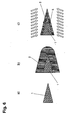
- FIG. 1 shows three different variants of blades, each made entirely of diamond.
- FIG. 1a shows a blade consisting of single crystal diamond.
- the rounding radius r of the cutting edge is indicated (detail D).
- FIG. 1b shows by default known in the art Volldiamantklingen based on polycrystalline diamond material.
- FIG. 1b the polymorphism of the arranged crystallite domains of the polycrystalline material is shown.
- Crystals from the blade in particular in the area preferably along grain boundaries of the cutting edge (see detail A) break out, so that the blade has, for example, already on first use an increased Schartmaschine. This results in a very inhomogeneous cutting edge, which significantly affects the cutting ability and the cutting edge of such a blade.
- FIG. 1c a blade of nano or fine crystalline diamond material is shown.
- the polycrystalline diamond blade shown is striking that the size, ie the diameter d of the respective crystallite domains, is designed to be many times smaller than with polycrystalline diamond (see in particular detail B and C). It is particularly advantageous that a breaking of the blade in the cutting area in comparison to the form of expression of the polycrystalline diamond according to FIG. 1b is significantly reduced, since the crystallites, which may possibly break out, are much smaller pronounced.
- damage to the blade compared to FIG. 1b detectable only on a microscopic scale, so that the macroscopic structure of the cutting edge of the blade according to Figure 1c essentially unimpaired.
- nanocrystalline crystallite domains of a blade according to Figure 1c lie below 500 nm, while polycrystalline diamond crystal domains have an average order of the crystallite domain d 50 between 2 and 100 microns.
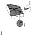
- FIG. 2 shows the basic structure of a cutting tool according to the present invention.
- a fine crystalline diamond layer 2 is arranged on a core 1.
- the core has two flanks tapering to a first, inner cutting edge, on the flanks of which the fine-crystalline diamond layer 2 is deposited.
- the diamond layer 2 in this case has a layer thickness y, which is measured orthogonally, for example, to an edge of the core 1. Also on the sides of the core that does not taper toward the first cutting edge, the diamond layer 2 may be applied, as in FIG FIG. 2 is shown.
- the diamond layer 2 follows the course of the two flanks of the core 1 and thus also tapers to a cutting edge, which closes off the diamond layer 2.
- the diamond layer 2 in this case has a layer thickness x, which corresponds to the smallest distance between the inner cutting edge of the core and the outer cutting edge, which is formed by the fine crystalline diamond layer 2.
- X is measured in the direction of the normal plane to the tangent of the outer cutting edge. Shown is also the cutting angle ⁇ , which is formed by the inclination of the outer edges of the cutting tool formed by the fine crystalline diamond layer.
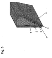
- FIG. 3 a further embodiment of the construction of the cutting tool according to the invention is shown.
- This cutting tool is formed asymmetrically with respect to the cutting edge 5.
- a core 1 is provided, on which a fine crystalline diamond layer 2 is deposited.
- an adhesion promoter layer 3 and a sliding layer 4 are further applied to the fine-grained diamond layer 2.
- a primer layer 3 come here, for example, vapor-deposited thin metal layers For example, from chromium, platinum, tungsten, titanium or silicon in question, while preferred sliding layers 4 polymer layers, for example of PTFE or carbon layers represent. The representation is not true to scale; usually the fine crystalline diamond layer is thicker than the primer layer.
- the core may consist, for example, of metallic materials or metal alloys, for example it is possible for the core material to be based on a steel material, a ceramic material or silicon.
- the following materials are suitable for the core: metals, such as titanium, nickel, chromium, niobium, tungsten, tantalum, molybdenum, vanadium, platinum, iron-containing materials, such as steel and / or germanium; carbon and / or nitrogen or boron-containing ceramics, such as silicon carbide, silicon nitride, boron nitride, tantalum carbide, tungsten carbide, molybdenum carbide, titanium nitrides, TiAlN, TiCN and / or TiB 2 , glass ceramics; Composites of ceramic materials in a metallic matrix (cermets); Hard metals; sintered carbide carbides such as cobalt or nickel bonded tungsten carbides or titanium carbides; Silicon, glass or sapphire; and single or polycrystalline
- the core material consists of monocrystalline or polycrystalline diamond;
- diamond-like carbon materials can be used for this purpose.
- the basic structure (with the exception of the metal layer 3 and the sliding layer 4) is therefore formed entirely of different diamond or diamond-like carbon materials.
- Fig. 3 also the cutting angle ⁇ is shown.
- FIG. 4 shows an embodiment of the present invention, which in principle has the same structure as in FIG. 3 shown, however, the cutting tool has a symmetrical design with respect to the cutting edge 5.
- Fig. 4 also the cutting angle ⁇ is shown.
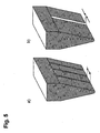
- FIG. 5 a further embodiment of the diamond blade according to the invention is shown, which has notches in the cutting edge.
- the core layer structure is not shown here for reasons of clarity.
- the notches are formed throughout by the diamond blade and can, for example, as in FIG. 5a shown to be formed at regular intervals.
- the regular spacing shown here may be, for example, less than 10 mm, for example 5 mm.
- FIG. 5b shows a further variant of the blade, wherein the notch is formed wider, the width of such a notch may for example be between 0.01 and 1 mm.
- FIG. 6 shows the basic process steps, which are passed through the inventive method for producing a cutting tool according to the invention.
- step a) a core material with an already predetermined cutting angle of the flanks is provided. Seed crystals of diamond are deposited on the flanks of the core material at least in certain areas (this step is not shown).
- step b) a finely crystalline diamond layer 2 is deposited by a method known from the prior art so that the cutting region, ie the region near the outer cutting edge, is completely covered with the fine-grained diamond layer 2.
- Step c) is a sharpening, ie a partial removal of the fine crystalline diamond layer; This step takes place by means of a plasma or ion etching process.
- FIG. 7 a further embodiment of a cutting tool according to the invention is shown, wherein the core is formed of polycrystalline materials, while on the fine crystalline diamond layer 2 is deposited. It can be seen that the average sizes of the crystallite domains of the core are much larger than the crystal domains of the fine crystalline diamond layer.
- hard metals, polycrystalline diamond, polycrystalline silicon, polycrystalline ceramic materials and / or polycrystalline metals can be used as core materials.
- FIG. 8 shows various embodiments of the cutting tool according to the invention, for example in the form of a machine knife a), a kitchen knife b) or differently designed blades c) or d). Also razor blades (see e)) are possible.
Landscapes
- Life Sciences & Earth Sciences (AREA)
- Forests & Forestry (AREA)
- Engineering & Computer Science (AREA)
- Mechanical Engineering (AREA)
- Cutting Tools, Boring Holders, And Turrets (AREA)
Description
Die vorliegende Erfindung betrifft ein Schneidwerkzeug, insbesondere in Form einer Rasierklinge, eines Skalpells, eines Messers, eines Maschinenmessers, einer Schere, etc., das eine synthetische Diamantschicht mit einer Schneidkante aufweist. Die Diamantschicht besteht dabei aus feinkristallinem Diamant.The present invention relates to a cutting tool, in particular in the form of a razor blade, a scalpel, a knife, a machine knife, a pair of scissors, etc., which has a synthetic diamond layer with a cutting edge. The diamond layer consists of fine crystalline diamond.
Schneidwerkzeuge, wie beispielsweise Messer und Skalpelle, die Diamantschichten aufweisen, sind bereits länger aus dem Stand der Technik bekannt. Diese Schneidwerkzeuge können dabei vollständig aus einer Diamantschicht gebildet sein (Volldiamantklinge), ebenso kann die Möglichkeit gegeben sein, dass eine synthetische Diamantschicht auf einem hierfür geeigneten Substrat aufgebracht ist. Zumeist ist die Schneidkante des Schneidwerkzeuges dabei in der Diamantschicht ausgebildet, da Diamant das härteste bekannteste Material ist.Cutting tools such as knives and scalpels having diamond layers have been known in the prior art for some time. These cutting tools can be completely formed from a diamond layer (full diamond blade), as well as the possibility can be given that a synthetic diamond layer is applied to a substrate suitable for this purpose. In most cases, the cutting edge of the cutting tool is formed in the diamond layer, since diamond is the hardest known Material is.
Diese Klingen zeichnen sich gegenüber beispielsweise Stahlklingen durch eine höhere Schneidfähigkeit (Schärfe) sowie eine höhere Schneidhaltigkeit (Lebensdauer, Standzeit) aus.These blades are distinguished from, for example, steel blades by a higher cutting ability (sharpness) and a higher cutting durability (life, service life).
Beispiele für die zuvor beschriebenen Diamantklingen mit einem derartigen prinzipiellen Aufbau finden sich in den Druckschriften
Die Diamantmaterialien, die für die aus dem Stand der Technik bekannten Klingen verwendet werden, sind dabei entweder polykristalline Diamantmaterialien, andererseits ist auch der Einsatz von einkristallinem Diamant möglich.The diamond materials that are used for the blades known from the prior art are either polycrystalline diamond materials, on the other hand, the use of single-crystal diamond is possible.
Derartige Diamantmaterialien weisen jedoch eine Reihe von Nachteilen auf.However, such diamond materials have a number of disadvantages.
Einkristalliner Diamant ist einerseits extrem schwierig herzustellen und zu bearbeiten, andererseits sehr teuer, so dass er für den Einsatz bei Massenprodukten, wie beispielsweise Rasierklingen, denkbar ungeeignet ist.On the one hand, single-crystal diamond is extremely difficult to produce and process, on the other hand it is very expensive, so that it is unsuitable for use in mass products such as razor blades.
Polykristalline Diamantschichten, wie sie im Stand der Technik verwendet werden, zeichnen sich durch eine deutlich heterogene Verteilung der Größe der kristallinen Domänen aus. Typischerweise variieren die Größen der kristallinen Bereiche bei polykristallinem Diamant über mehrere Größenordnungen. Hierbei finden sich Verteilungen, bei denen die größten auftretenden Kristallitdomänen einen Durchmesser aufweisen, der um einen Faktor 100 größer ist als der Durchmesser der kleinsten auftretenden kristallinen Domänen, wobei typische Werte für die durchschnittliche Größe der Kristallite d50 zwischen 2 und 100 µm liegen. Gemäß dieser Definition liegen zumindest 50 % der Kristallite mit einer durchschnittlichen Größe zwischen 2 und 100 µm vor. Eine derartige polykristalline Diamantschicht ist damit sehr heterogen, jedoch kostengünstig herzustellen.Polycrystalline diamond layers, as used in the prior art, are characterized by a clearly heterogeneous distribution of the size of the crystalline domains. Typically, the sizes of the crystalline regions in polycrystalline diamond vary over several orders of magnitude. Here are distributions in which the largest occurring crystallite domains have a diameter, which is larger by a factor of 100 than the diameter of the smallest occurring crystalline domains, with typical values for the average size of the crystallites d 50 being between 2 and 100 μm. According to this definition, at least 50% of the crystallites are present with an average size between 2 and 100 μm. Such a polycrystalline diamond layer is thus very heterogeneous, but inexpensive to produce.
Bei derartigen polykristallinen heterogenen Diamantschichten hat es sich als nachteilig gezeigt, dass aufgrund der Heterogenität der kristallinen Domänen diese Klingen äußerst schwer anzuschärfen sind. Selbst für den Fall, dass eine zuverlässige Schneide, d.h. eine glatte und durchgehende Schneide, aus polykristallinem Diamant hergestellt werden kann, ist zu beobachten, dass aufgrund der heterogenen Kristalldomänen bereits beim erstmaligen Gebrauch eine Schartigkeit zu beobachten ist. Dies ist auf die beim Schneidvorgang auf die Schneidkante auftretenden hohen Schneidkräfte zurückzuführen, wobei stets ein gewisser Anteil vorhandener Kristallite aus dem Kristallitverband herausbricht. Die Größe des Ausbruchs richtet sich dabei nach der Korngröße. Beispielsweise bei Anwendungen, wie Rasierklingen, ist dies jedoch nicht wünschenswert, da derartige Schartigkeiten oder Ausbrüche schnell zu einem Verlust der Schneidfähigkeit oder Erhöhung der Schneidkräfte führen, was sich z.B. in einem schmerzhaften Gefühl bei der Rasur äußern kann, da Verletzungen der Haut auftreten können.In such polycrystalline heterogeneous diamond layers, it has proved to be disadvantageous that due to the heterogeneity of the crystalline domains these blades are extremely difficult to sharpen. Even in the case where a reliable cutting edge, i. a smooth and continuous cutting edge, can be made of polycrystalline diamond, it can be observed that due to the heterogeneous crystal domains already on first use a Schartigkeit is observed. This is due to the high cutting forces occurring on the cutting edge during the cutting process, with a certain proportion of existing crystallites always breaking out of the crystallite bond. The size of the outbreak depends on the grain size. For example, in applications such as razor blades, however, this is undesirable because such scores or breakouts rapidly result in a loss of cutting ability or an increase in cutting forces, resulting in e.g. may express a painful sensation when shaving, as skin injuries may occur.
Aufgrund der polykristallinen Struktur und der Ausbildung einer Textur, weisen polykristalline Diamantschichten auf der Wachstumsseite eine hohe Oberflächenrauheit auf. Diese ist liegt in der Regel über rms>1µm.Due to the polycrystalline structure and the formation of a texture, polycrystalline diamond layers on the growth side have high surface roughness on. This is usually about rms> 1μm.
Dies macht somit eine nachträgliche Politur von polykristallinen Schichten notwendig, um glatte Oberflächen zu erhalten.This therefore necessitates a subsequent polishing of polycrystalline layers in order to obtain smooth surfaces.
Ferner weisen polykristalline Diamantschichten im Querbruch eine kolumnare Struktur auf, d.h. die Korngrenzen verlaufen im Wesentlichen senkrecht zur Substratoberfläche. Da die Korngrenze einen makroskopischen Defekt darstellt, wirkt sie wie eine Sollbruchstelle. Ungünstigerweise beinhalten polykristalline Diamantschichten eine Vielzahl dieser Sollbruchstellen und sind deshalb sehr bruchanfällig. So liegt etwa die Biegebruchspannung σ0 bei polykristallinen Schichten etwa bei ca. 1/10 derer von einkristallinem Diamant.Furthermore, polycrystalline diamond layers in the transverse fracture have a columnar structure, ie the grain boundaries are substantially perpendicular to the substrate surface. Since the grain boundary represents a macroscopic defect, it acts like a predetermined breaking point. Unfortunately, polycrystalline diamond layers contain a large number of these predetermined breaking points and are therefore very susceptible to breakage. For example, the bending stress σ 0 for polycrystalline layers is about 1/10 that of monocrystalline diamond.
Durch den heterogenen Aufbau polykristalliner Diamantschichten weisen diese auch meist innere mechanische Spannungen auf, die sich makroskopisch durch einen Verzug der Schichten äußern. Neben den damit verbundenen Problemen der Durchbiegung (Verzug) der Schneidkante verringern diese zusätzlich die Bruchspannung und führen somit zu erhöhter Bruchanfälligkeit.Due to the heterogeneous structure of polycrystalline diamond layers, these also mostly have internal mechanical stresses, which manifest themselves macroscopically through a distortion of the layers. In addition to the associated problems of deflection (distortion) of the cutting edge, these additionally reduce the breaking stress and thus lead to increased susceptibility to breakage.
Ausgehend von den aus dem Stand der Technik bekannten Nachteilen ist es daher Aufgabe der vorliegenden Erfindung, ein Schneidwerkzeug anzugeben, das kostengünstig und zuverlässig herstellbar ist, eine zumindest gleiche hohe Schneidfähigkeit und Schneidhaltigkeit gegenüber den aus dem Stand der Technik bekannten Diamantklingen aufweist und bei dem Ausbrüche, wie sie bei den polykristallinen Diamant-Schneidwerkzeugen bekannt sind, nur in untergeordneter Ordnung auftreten.Based on the known from the prior art disadvantages, it is therefore an object of the present invention to provide a cutting tool that is inexpensive and reliable to produce, has at least the same high cutting ability and cutting edge over the known from the prior art diamond blades and the outbreaks as with the polycrystalline diamond cutting tools are known to occur only in subordinate order.
Diese Aufgabe wird bezüglich eines Schneidwerkzeugs mit den Merkmalen des Patentanspruchs 1 gelöst. Verwendungen werden in Anspruch 14 genannt. Die bevorzugten Ausführungsformen stellen dabei vorteilhafte Weiterbildungen dar.This object is achieved with respect to a cutting tool having the features of
Erfindungsgemäß wird somit ein Schneidwerkzeug bereitgestellt, das
- a) einen Kern, der zwei sich zu einer inneren Schneide verjüngende Flanken aufweist, wobei die innere Schneide einen ersten Verrundungsradius r1 aufweist, sowie
- b) eine zumindest im Bereich der inneren Schneide und zumindest teilweise auf den Flanken des Kerns aufgebrachte feinkristalline Diamantschicht, mit einer mittleren Korngröße d50 ≤ 100 nm, die dem Verlauf der verjüngenden Flanken des Kerns folgend zu einer äußeren Schneide zusammenläuft, wobei die feinkristalline Diamantschicht im Bereich der Flanken eine Schichtdicke y und im Bereich der Schneide einen zweiten verrundungsradius r2 aufweist,
- a) a core having two flanks tapered to an inner cutting edge, the inner cutting edge having a first radius of curvature r 1 , and
- b) an at least in the region of the inner edge and at least partially on the flanks of the core applied fine crystalline diamond layer, having a mean grain size d 50 ≤ 100 nm, which converges the course of the tapered flanks of the core to form an outer edge, wherein the finely crystalline diamond layer has a layer thickness y in the region of the flanks and a second rounding radius r 2 in the region of the cutting edge,
Die innere Schneide stellt dabei die Stelle dar, an der die sich verjüngenden Flanken des Kerns zu einer inneren (Schneid-)Kante zusammenlaufen. Die feinkristalline Diamantschicht, die auf dem Kern aufgebracht ist, folgt dabei dem Verlauf der sich verjüngenden Kanten, wobei sich ebenso eine Schneidkante in der feinkristallinen Diamantschicht ausbildet, die "äußere" Schneidkante. Die äußere Schneidkante bildet dabei die eigentliche Schneide des Schneidwerkzeugs.The inner cutting edge represents the point at which the tapering flanks of the core converge to form an inner (cutting) edge. The fine crystalline diamond layer, which is applied to the core, follows the course of the tapered Edges, wherein also forms a cutting edge in the fine crystalline diamond layer, the "outer" cutting edge. The outer cutting edge forms the actual cutting edge of the cutting tool.
Maßgeblich ist dabei, dass der Verrundungsradius r2 der äußeren Schneidkante kleiner ist als der der inneren Schneidkante des Kerns r1.Decisive here is that the radius of curvature r 2 of the outer cutting edge is smaller than that of the inner cutting edge of the core r 1 .
Alle aus dem Stand der Technik bekannten Beschichtungsverfahren zeichnen sich dadurch aus, dass der Verrundungsradius der äußeren Schneidkante r2 größer ist als der der Schneidkante des Kerns. Das heißt, dass jegliches Aufbringen einer verschleißschutzschicht einem Scheidfähigkeitsverlust (Schärfeverlust) gleichkommt. Aus diesem Grund muss nach dem Stand der Technik grundsätzlich ein Kompromiss zwischen der Schneidhaltigkeit und Schneidfähigkeit der Schneiden gefunden werden. Die verwendeten Schichtdicken von harten verschleißschutzschichten sind deshalb in der Regel in Ihrer Schichtdicke limitiert und meist sehr dünn (< 1µm).All coating methods known from the prior art are characterized in that the radius of curvature of the outer cutting edge r 2 is greater than that of the cutting edge of the core. That is, any application of a wear protection layer equals a loss of dependency (sharpness loss). For this reason, a compromise between the cutting strength and cutting ability of the cutting must always be found in the prior art. The layer thicknesses of hard wear protection layers used are therefore usually limited in their layer thickness and usually very thin (<1μm).
Erfindungsgemäß wird unter feinkristallinem Diamant eine Diamantschicht verstanden, wobei die kristallinen Domänen eine mittlere Korngröße d50 von ≤ 100 nm aufweisen. Hierunter wird verstanden, dass zumindest bei 50 % der Kristallite jede Dimension eines einzelnen Kristallits ≤ 100 nm ist. Die fein-kristalline Diamantschicht zeichnet sich somit durch eine äußerst hohe Homogenität der Kristallite aus.According to the invention, finely crystalline diamond is understood to mean a diamond layer, the crystalline domains having an average particle size d 50 of ≦ 100 nm. By this is meant that at least 50% of the crystallites have each dimension of a single crystallite ≤ 100 nm. The fine-crystalline diamond layer is thus characterized by an extremely high homogeneity of the crystallites.
Überraschenderweise konnte gefunden werden, dass bei Schneidkanten, die aus derartigen feinkristallinen Diamantschichten gebildet sind (gemäß der obenstehend angegebenen Definition ist dies die äußere Schneidkante), ein Ausbrechen, wie es von polykristallinem Diamant bekannt ist, quasi vollständig unterbleibt. Gegenüber einkristallinem Diamant hat sich gezeigt, dass die Herstellung von feinkristallinem Diamant verglichen mit der Herstellung von einkristallinem Diamant wesentlich einfacher und kostengünstiger zu bewerkstelligen ist. Somit können auch längere und/oder großflächigere Diamantklingen bereitgestellt werden, wie sie z.B. in Rasierern Verwendung finden, was bei Diamantklingen aus einkristallinem Diamant bislang nicht möglich war.Surprisingly, it has been found that in the case of cutting edges which are formed from such fine-grained diamond layers (according to the definition given above, this is the outer cutting edge), a breakdown, as it is known from polycrystalline diamond, quasi completely omitted. Compared with monocrystalline diamond, it has been found that the production of fine crystalline diamond is much easier and cheaper to accomplish compared to the production of single crystal diamond. Thus, longer and / or larger-area diamond blades can be provided, as they are used in razors, for example, which was previously not possible with diamond blades made of monocrystalline diamond.
Aufgrund der extrem hohen Biegebruchspannung des feinkristallinen Diamants (σ0 ~ 5,7 GPa) wird erreicht, dass trotz hoher lokaler mechanischer Beanspruchung ein Ausbrechen einzelner Kristallite aus der feinkristallinen Diamantschicht, insbesondere aus der äußeren Schneidkante, fast vollständig unterbleibt. Auch bei längerem Gebrauch behält daher das Schneidwerkzeug seine ursprüngliche Schärfe nahezu vollständig bei.Due to the extremely high bending stress of the fine crystalline diamond (σ 0 ~ 5.7 GPa) it is achieved that, despite high local mechanical stress, break-off of individual crystallites from the fine-crystalline diamond layer, in particular from the outer cutting edge, is almost completely eliminated. Even with prolonged use, therefore, the cutting tool retains its original sharpness almost completely.
Bezüglich der Definition der Biegebruchspannung σ0 wird auf die folgenden Literaturstellen verwiesen:
-
R. Morrell et al., Int. Journal of Refractory Metals & Hard Materials, 28 (2010), S. 508-515 -
R. Danzer et al. in "Technische keramische Werkstoffe", herausgegeben von J. Kriegesmann, HvB Verlag, Ellerau, ISBN 978-3-938595-00-8, Kapitel 6.2.3.1 - Der 4-Kugelversuch zur Ermittlung der biaxialen Biegefestigkeit spröder Werkstoffe
-
R. Morrell et al., Int. Journal of Refractory Metals & Hard Materials, 28 (2010), pp. 508-515 -
R. Danzer et al. in "technical ceramic materials", edited by J. Kriegesmann, HvB Verlag, Ellerau, ISBN 978-3-938595-00-8, chapter 6.2.3.1 - The 4-ball test to determine the biaxial bending strength of brittle materials
Die Biegebruchspannung σ0 wird dabei durch statistische Auswertung von Bruchversuchen z.B. im B3B Belastungsversuch gemäß den oben stehenden Literaturangaben ermittelt. Sie ist dabei definiert als die Bruchspannung, bei der eine Bruchwahrscheinlichkeit von 63 % vorliegt.The bending stress σ 0 is determined by statistical evaluation of fracture tests, eg in the B3B load test determined according to the above references. It is defined as the breaking stress at which the probability of breakage is 63%.
Da feinkristalline Diamantschichten bezüglich Ihrer Korngrößenverteilung homogener sind als polykristalline Diamantschichten, weist das Material auch weniger Eigenspannungen auf. Dadurch ist ein makroskopischer Verzug der Schneide weniger wahrscheinlich.Since finely crystalline diamond layers are more homogeneous with respect to their particle size distribution than polycrystalline diamond layers, the material also has lower residual stresses. As a result, a macroscopic distortion of the cutting edge is less likely.
Die erfindungsgemäßen Schneidwerkzeuge können dabei bezüglich der Schneide symmetrisch oder asymmetrisch ausgebildet sein. Insbesondere ist es möglich, dass das Schneidwerkzeug eine Fase aufweisen kann, d.h. einen zweiten Winkel an der Schneide. Diese Fase kann z.B. im Kern ausgebildet sein und durch gleichmäßige Beschichtung mit der feinkristallinen Diamantschicht an die Oberfläche des Schneidwerkzeugs fortgeführt werden, zusätzlich oder alternativ hierzu ist jedoch ebenso die Ausbildung der Fase in der feinkristallinen Diamantschicht möglich.The cutting tools according to the invention can be formed symmetrically or asymmetrically with respect to the cutting edge. In particular, it is possible that the cutting tool may have a chamfer, i. a second angle at the cutting edge. This chamfer can e.g. be formed in the core and be continued by uniform coating with the fine crystalline diamond layer to the surface of the cutting tool, in addition to or alternatively, however, also the formation of the bevel in the fine crystalline diamond layer is possible.
In einer bevorzugten Ausführungsform ist vorgesehen, dass unabhängig voneinander
- a) der erste Verrundungsradius r1 zwischen 4 nm und 20 µm,
bevorzugt zwischen 0,1 und 5 µm, besonders bevorzugt zwischen 0,5 und 3 µm und/oder - b) der zweite Verrundungsradius r2 zwischen 3 und 100 nm, bevorzugt zwischen 15 und 70 nm, besonders bevorzugt zwischen 20 und 50 nm beträgt.
- a) the first rounding radius r 1 between 4 nm and 20 microns, preferably between 0.1 and 5 microns, more preferably between 0.5 and 3 microns and / or
- b) the second rounding radius r 2 is between 3 and 100 nm, preferably between 15 and 70 nm, particularly preferably between 20 and 50 nm.
Weiter ist bevorzugt, wenn die Schichtdicke y der feinkristallinen Diamantschicht zwischen 1 und 500 µm, bevorzugt zwischen 1 und 50 µm, besonders bevorzugt zwischen 2 und 10 µm beträgt. Die Schichtdicke y der feinkristallinen Diamantschicht wird dabei im Bereich der die Schneide bildenden Flanken des Kerns und orthogonal zu dieser Flanke bestimmt.It is further preferred if the layer thickness y of the fine-crystalline diamond layer is between 1 and 500 μm, preferably between 1 and 50 μm, particularly preferably between 2 and 10 microns. The layer thickness y of the fine-crystalline diamond layer is determined in the region of the flanks of the core forming the cutting edge and orthogonal to this flank.
Gemäß der Erfindung ist vorgesehen, dass die feinkristalline Diamantschicht in Projektion auf die innere Schneide eine Schichtdicke x aufweist, mit der Maßgabe, dass 0,1 ≤ y/x ≤ 0,6, bevorzugt 0,12 ≤ y/x ≤ 0,5, besonders bevorzugt 0,13 ≤ y/x ≤ 0,25 ist. Diese Ausführungsform wird nachstehend anhand der beigefügten Figuren näher erläutert. Die Schichtdicke x entspricht der kleinsten Distanz zwischen der inneren Schneidkante des Kerns und der äußeren Schneidkante, die in der feinkristallinen Diamantschicht ausgebildet ist. Die Schichtdicke wird dabei in Richtung der Normalenebene an der Tangente der äußeren Schneidkante gemessen. Die Schichtdicke x entspricht daher dem Abstand der äußeren Schneidkante der feinkristallinen Diamantschicht und der inneren Schneidkante des Kerns.According to the invention, it is provided that the fine-crystalline diamond layer has a layer thickness x projected onto the inner cutting edge, with the proviso that 0.1 ≦ y / x ≦ 0.6, preferably 0.12 ≦ y / x ≦ 0.5 , particularly preferably 0.13 ≦ y / x ≦ 0.25. This embodiment will be explained below with reference to the accompanying figures. The layer thickness x corresponds to the smallest distance between the inner cutting edge of the core and the outer cutting edge formed in the fine crystalline diamond layer. The layer thickness is measured in the direction of the normal plane at the tangent of the outer cutting edge. The layer thickness x therefore corresponds to the distance of the outer cutting edge of the fine-grained diamond layer and the inner cutting edge of the core.
Weiter ist bevorzugt, wenn die mittlere Korngröße d50 des feinkristallinen Diamants bevorzugt zwischen 5 und 100 nm, besonders bevorzugt zwischen 10 und 70 nm beträgt.It is further preferred if the average particle size d 50 of the finely crystalline diamond is preferably between 5 and 100 nm, particularly preferably between 10 and 70 nm.
Bevorzugte Schneidwinkel β liegen dabei zwischen 10° und 40°, bevorzugt zwischen 10° und 30°, besonders zwischen 15° und 25°. Der Schneidwinkel ß wird dabei durch die feinkristalline Diamantschicht bestimmt, d.h. ist durch den Winkel definiert, unter dem die äußeren Oberflächen des Schneidwerkzeugs an der äußeren Schneidkante zusammenlaufen.Preferred cutting angles β are between 10 ° and 40 °, preferably between 10 ° and 30 °, especially between 15 ° and 25 °. The cutting angle β is determined by the finely crystalline diamond layer, ie defined by the angle at which the outer surfaces of the cutting tool converge on the outer cutting edge.
Ein bevorzugter Anteil an sp- und sp2-Bindungen der feinkristallinen Diamantschicht liegt dabei zwischen 0,5 und 10 %, bevorzugt zwischen 2 und 9 %, besonders bevorzugt zwischen 3 und 8 %. Ein höherer sp2-Anteil bewirkt dabei, dass das E-Modul der feinkristallinen Diamantschicht etwas erniedrigt wird. Gleichzeitig sinkt ebenso die Härte dieses Materials. Dadurch werden die feinkristallinen Diamantschichten insgesamt flexibler und elastischer und können sich dem Schneidgut bzw. der Kontur des Schneidguts besser anpassen. Gleichzeitig wird eine optimale Anpassung an das Kernmaterial gewährleistet, was die Wahrscheinlichkeit der Delamination der feinkristallinen Diamantschicht herabsetzt.A preferred proportion of sp and sp 2 bonds of the finely crystalline diamond layer is between 0.5 and 10%, preferably between 2 and 9%, particularly preferably between 3 and 8%. A higher sp 2 content causes the modulus of elasticity of the fine-grained diamond layer to be slightly lowered. At the same time, the hardness of this material also decreases. As a result, the fine-crystalline diamond layers become more flexible and elastic overall and can better adapt to the material to be cut or the contour of the material to be cut. At the same time, an optimal adaptation to the core material is ensured, which reduces the likelihood of delamination of the fine crystalline diamond layer.
Vorteilhafte Kernmaterialien sind dabei ausgewählt aus der Gruppe bestehend aus Metallen, wie Titan, Nickel, Chrom, Niob, Wolfram, Tantal, Molybdän, Vanadium, Platin, eisenhaltigen Werkstoffen wie Stahl und/oder Germanium; aus kohlenstoff- und/oder stickstoff- oder bor-haltigen Keramiken, wie Siliziumkarbid, Siliziumnitrid, Bornitrid, Tantalkarbid, Wolframkarbid, Molybdänkarbid, Titannitride, TiAlN, TiCN und/oder TiB2, Glaskeramiken; Verbundwerkstoffen aus keramischen Werkstoffen in einer metallischen Matrix (Cermets); Hartmetallen; gesinterten Carbidhartmetallen, wie z.B. Cobalt- oder Nickel-gebundenen Wolframcarbiden oder Titancarbiden; Silizium, Glas oder Saphir; sowie ein- oder polykristallinem Diamant und/oder diamantartigen Kohlenstoffschichten.Advantageous core materials are selected from the group consisting of metals such as titanium, nickel, chromium, niobium, tungsten, tantalum, molybdenum, vanadium, platinum, iron-containing materials such as steel and / or germanium; from carbon and / or nitrogen or boron-containing ceramics, such as silicon carbide, silicon nitride, boron nitride, tantalum carbide, tungsten carbide, molybdenum carbide, titanium nitrides, TiAlN, TiCN and / or TiB 2 , glass ceramics; Composites of ceramic materials in a metallic matrix (cermets); Hard metals; sintered carbide carbides such as cobalt or nickel bonded tungsten carbides or titanium carbides; Silicon, glass or sapphire; and monocrystalline or polycrystalline diamond and / or diamond-like carbon layers.
Die Erfindung sieht somit vor, dass der Kern beispielsweise aus gängigen Metallen oder Legierungen gebildet wird, ebenso ist vorgesehen, dass der Kern auch aus ein- bzw. polykristallinem Diamant oder diamantartigen Kohlenstoffmaterialien gebildet sein kann. In diesem Sinne könnte man bei der zuletzt genannten Ausführungsform auch von einer "Volldiamantklinge" sprechen, wobei jedoch zwei verschiedene Diamantmaterialien verwendet werden.The invention thus provides that the core is formed, for example, from common metals or alloys, it is also provided that the core may also be formed from single or polycrystalline diamond or diamond-like carbon materials can. In this sense, one could also speak of a "full diamond blade" in the latter embodiment, but with two different diamond materials are used.
Für den Fall, dass polykristalline Materialien als Kernmaterialien verwendet werden, ist es vorteilhaft, wenn der durchschnittliche Korndurchmesser d50 der die äußere Schneide bildenden feinkristallinen Diamantschicht kleiner ist als der durchschnittliche Korndurchmesser d50 des Kernmaterials.In the case where polycrystalline materials are used as core materials, it is preferable that the average grain diameter d 50 of the fine-grained diamond layer forming the outer blade is smaller than the average grain diameter d 50 of the core material.
In einer bevorzugten Ausführungsform beträgt die Biegebruchspannung σ0 der Diamantschicht > 2 GPa, bevorzugt > 4 GPa, besonders bevorzugt > 5 GPa. σ0 ist dabei wie oben stehend definiert.In a preferred embodiment, the bending fracture stress σ 0 of the diamond layer is> 2 GPa, preferably> 4 GPa, particularly preferably> 5 GPa. σ 0 is defined as above.
In einer weiteren bevorzugten Ausführungsform beträgt der E-Modul der Diamantschicht < 1.200 GPa, bevorzugt < 900, besonders bevorzugt < 750 GPa.In a further preferred embodiment, the modulus of elasticity of the diamond layer is <1.200 GPa, preferably <900, particularly preferably <750 GPa.
Eine weitere bevorzugte Ausführungsform sieht vor, dass das Verhältnis r2/d50 des Verrundungsradius der Diamantschicht an der äußeren Schneidkante zur mittleren Korngröße des feinkristallinen Diamants zwischen 0,03 und 20, bevorzugt zwischen 0,05 und 15, besonders bevorzugt zwischen 0,5 und 10 liegt.A further preferred embodiment provides that the ratio r 2 / d 50 of the radius of curvature of the diamond layer at the outer cutting edge to the mean grain size of the fine crystalline diamond is between 0.03 and 20, preferably between 0.05 and 15, particularly preferably between 0.5 and 10 lies.
Weiterhin ist vorteilhaft, wenn der in Richtung der Dicke y der feinkristallinen Diamantschicht gemessene Gradient der mittleren Korngröße des feinkristallinen Diamants < 300 %, bevorzugt < 100 %, besonders bevorzugt < 50 % beträgt. Diese Ausführungsform sieht vor, dass der mittlere Korngrößendurchmesser der feinkristallinen Domänen der Diamantschicht durch die gesamte Schichtdicke hindurch relativ gleichmäßig bis besonders gleichmäßig verteilt ist, d.h. die Korngrößen sind auf der einen Seite der Diamantschicht ca. gleich groß wie auf der anderen Seite der Diamantschicht; besonders vorteilhaft ist dabei natürlich eine nahezu oder eine vollständig komplette Homogenität der feinkristallinen Domänen der Diamantschicht. Der Gradient wird dadurch bestimmt, dass der mittlere Korngrößendurchmesser d50 auf einer Seite der Diamantschicht ermittelt wird und in Bezug zum mittleren Korngrößendurchmesser auf der gegenüber liegenden Seite der Diamantschicht in Bezug gesetzt wird.It is furthermore advantageous if the gradient of the average grain size of the fine-crystalline diamond measured in the direction of the thickness y of the fine-crystalline diamond layer is <300%, preferably <100%, particularly preferably <50%. This embodiment provides that the mean grain size diameter of the fine-grained domains of the diamond layer through the entire layer thickness is relatively uniform to particularly is evenly distributed, ie the grain sizes are approximately the same size on one side of the diamond layer as on the other side of the diamond layer; Of course, it is particularly advantageous in this case for a virtually complete or complete complete homogeneity of the finely crystalline domains of the diamond layer. The gradient is determined by determining the average grain size diameter d 50 on one side of the diamond layer and relating it to the average grain size diameter on the opposite side of the diamond layer.
Besonders bevorzugte Ausführungsformen sehen vor, dass beispielsweise zwischen dem Kern und der feinkristallinen Diamantschicht mindestens eine erste Haftvermittlerschicht, bevorzugt aus Siliziumkarbid, Siliziumnitrid, Wolfram, Titan oder Silizium angeordnet ist. Die erste Haftvermittlerschicht erhöht dabei die Stärke des mechanischen Verbunds zwischen Kern und feinkristalliner Diamantschicht.Particularly preferred embodiments provide that, for example, between the core and the fine-crystalline diamond layer, at least one first adhesion promoter layer, preferably of silicon carbide, silicon nitride, tungsten, titanium or silicon, is arranged. The first adhesion promoter layer thereby increases the strength of the mechanical bond between the core and the fine-crystalline diamond layer.
Zudem ist es unabhängig von der zuvor genannten Ausführungsform ebenso möglich, dass zusätzlich oder alternativ hierzu auf der feinkristallinen Diamantschicht mindestens eine zweite Haftvermittlerschicht, bevorzugt aus Cr, Pt, Ti oder W, sowie darauf eine Gleitschicht, insbesondere eine Polymerschicht, bevorzugt eine PTFE-Schicht, eine Kohlenstoffschicht, bevorzugt eine Graphitschicht und/oder eine DLC-Schicht, aufgebracht ist. Die zweite Haftvermittlerschicht dient ebenso der besseren Anbindung der Gleitschicht an die feinkristalline Diamantschicht. Für den Fall, dass Kohlenstoffschichten, Graphit-oder DLC-Schichten als Gleitschicht verwendet werden, kann auf die zweite Haftvermittlerschicht auch verzichtet werden, da ein direktes Anbinden der Kohlenstoffschichten an die feinkristalline Diamantschicht möglich ist. Die Gleitschicht dient dabei der Reibungsminimierung zwischen Schneidwerkzeug und Schneidgut. Ebenso wird eine Minimierung von Schmutzanhaftung, eine Vermeidung von Schneidstaub sowie eine Verringerung der Schneidkräfte erreicht.In addition, it is also possible, irrespective of the aforementioned embodiment, that additionally or alternatively on the fine-crystalline diamond layer at least one second adhesion promoter layer, preferably of Cr, Pt, Ti or W, and thereon a sliding layer, in particular a polymer layer, preferably a PTFE layer , a carbon layer, preferably a graphite layer and / or a DLC layer, is applied. The second adhesion promoter layer also serves to better bond the sliding layer to the fine crystalline diamond layer. In the event that carbon layers, graphite or DLC layers are used as a sliding layer, can also be dispensed with the second adhesion promoter layer, since a direct bonding of the carbon layers to the fine crystalline diamond layer is possible. The sliding layer serves to minimize friction between the cutting tool and cutting material. Likewise, a minimization of dirt adhesion, avoidance of cutting dust and a reduction of the cutting forces is achieved.
Die Diamantschicht ist dabei bevorzugt sehr glatt ausgebildet, d.h. weist eine mittlere Oberflächenrauigkeit von RA < 5µm, bevorzugt < 2µm, weiter bevorzugt < 1µm auf. Dies macht eine zusätzliche mechanische Politur der gewachsenen Diamantoberfläche überflüssig.The diamond layer is preferably very smooth, ie has an average surface roughness of R A <5 .mu.m, preferably <2 .mu.m, more preferably <1 .mu.m. This makes an additional mechanical polishing of the grown diamond surface superfluous.
Eine weitere bevorzugte Ausführungsform des Schneidwerkzeugs sieht vor, dass das Schneidwerkzeug in regelmäßigen Abständen, bevorzugt in regelmäßigen Abständen von weniger als 10 mm, Einkerbungen oder Durchtrennungen aufweist. Diese Einkerbungen in die Klinge bzw. die Durchtrennungen der Klinge bis zum Rumpf hin können dabei in regelmäßigen Abständen von kleiner 10 mm ausgebildet sein. Bevorzugte Abstände liegen dabei beispielsweise zwischen 5 und 9 mm. Diese Einkerbungen ermöglichen eine Führung der Klinge relativ zum Schneidgut und somit eine Stabilisierung des Schneidwerkzeugs während des Schneidvorganges.A further preferred embodiment of the cutting tool provides that the cutting tool has notches or cuts at regular intervals, preferably at regular intervals of less than 10 mm. These notches in the blade or the cuts of the blade to the fuselage can be formed at regular intervals of less than 10 mm. Preferred distances are for example between 5 and 9 mm. These indentations allow the blade to be guided relative to the material to be cut, thus stabilizing the cutting tool during the cutting process.
Eine weitere bevorzugte Ausführungsform sieht vor, dass die Kristallite der feinkristallinen Diamantschicht bevorzugt in <100>-, <110>- und/oder <111>-Richtung aufgewachsen sind, d.h. eine Textur vorliegt. Dies kann aus dem Herstellungsprozess resultieren, bei dem die Wachstumsgeschwindigkeit bestimmter Kristallrichtungen gezielt bevorzugt werden kann. Diese anisotrope Textur der Kristallite beeinflusst die mechanischen Eigenschaften ebenso positiv. Insbesondere ist das Schneidwerkzeug als Klinge, Messerklinge, Rasierklinge, Skalpell, Messer, Maschinenmesser, Schere oder Maschinenschere ausgebildet bzw. kann als solches verwendet werden. Ebenso ist es möglich, dass das Schneidwerkzeug als Rasiersystem, d.h. als Kopf mit mehreren Rasierklingen ausgebildet ist bzw. als solches verwendet werden kann. Dabei sind alle Rasierklingen als erfindungsgemäßes Schneidwerkzeug ausgebildet.A further preferred embodiment provides that the crystallites of the finely crystalline diamond layer are preferably grown in the <100>, <110> and / or <111> direction, ie a texture is present. This can result from the manufacturing process, in which the growth rate of certain crystal directions can be specifically favored. This anisotropic texture of the crystallites also positively affects the mechanical properties. In particular, the cutting tool is designed as a blade, knife blade, razor blade, scalpel, knife, machine knife, scissors or machine shears or can be used as such. It is also possible that the cutting tool is designed as a shaving system, ie as a head with a plurality of razor blades or can be used as such. All razor blades are designed as cutting tools according to the invention.
Erfindungsgemäß wird ebenso ein Verfahren zur Herstellung eines zuvor beschriebenen Schneidwerkzeugs angegeben, bei dem
- a) ein Kern mit zwei sich zu einer inneren Schneide verjüngenden Flanken bereitgestellt wird,
- b) zumindest auf Teilen der Flanken des Kerns sowie der inneren Schneide feinkristalline Diamantimpfkristalle abgeschieden werden,
- c) eine feinkristalline Diamantschicht an den Stellen, an denen die Impfkristalle aufgebracht sind, mittels eines CVD-Prozesses aufgewachsen wird, wobei sich eine durchgängige feinkristalline Diamantschicht mit einer äußeren Schneide ausbildet, sowie
- d) die feinkristalline Diamantschicht im Bereich der äußeren Schneide mittels eines Plasma- oder
- a) a core is provided with two flanks tapering to an inner cutting edge,
- b) depositing finely crystalline diamond seed crystals on at least parts of the flanks of the core and the inner cutting edge,
- c) a fine crystalline diamond layer is grown at the locations where the seed crystals are applied, by means of a CVD process, wherein a continuous fine-crystalline diamond layer is formed with an outer edge, and
- d) the finely crystalline diamond layer in the region of the outer edge by means of a plasma or
Ionenätzverfahrens geschärft und gegebenenfalls geglättet wird.Ion etching is sharpened and optionally smoothed.
In Schritt c) kann das Abscheiden der feinkristallinen Diamantschicht z.B. auf die im folgenden Beispiel angegebene Weise erfolgen.In step c), the deposition of the fine crystalline diamond layer can be carried out, for example, in the manner given in the following example.
Die feinkristallinen Diamantschichten werden z.B. mittels eines "Heißdraht-CVD-Verfahrens" hergestellt. Bei diesem Verfahren wird in einer Vakuumkammer mittels heißer Drähte, z.B. Wolframdrähte, eine Gasphase bestehend aus z.B. 1 bis 5 Vol.-% CH4 und 95 bis 99 Vol.-% Wasserstoff aktiviert. Die Drahttemperatur liegt beispielsweise in einem Bereich von 1.800°C bis 2.400°C. Bei einem Abstand zwischen dem Substrat und den Drähten von 1 cm bis 5 cm wird dabei eine Substrattemperatur von 600 °C bis 900 °C eingestellt. Der Druck der Gasatmosphäre liegt zwischen 3 mbar und 30 mbar. Dabei erfolgt eine Abscheidung der feinkristallinen Diamantschicht auf dem Substrat.The fine-crystalline diamond films are produced, for example, by means of a "hot-wire CVD process". In this method, in a vacuum chamber by means of hot wires, such as tungsten wires, a gas phase consisting of, for example 1 to 5 vol .-% CH 4 and 95 to 99 vol .-% hydrogen activated. The wire temperature is, for example, in a range of 1,800 ° C to 2,400 ° C. At a distance between the substrate and the wires of 1 cm to 5 cm while a substrate temperature of 600 ° C to 900 ° C is set. The pressure of the gas atmosphere is between 3 mbar and 30 mbar. In this case, the fine-grained diamond layer is deposited on the substrate.
Optional kann vor Schritt b) mindestens eine erste Haftvermittlerschicht auf dem Kern abgeschieden und die Impfkristalle auf der mindestens einen ersten Haftvermittlerschicht abgeschieden werden.Optionally, at least one first adhesion promoter layer can be deposited on the core before step b) and the seed crystals deposited on the at least one first adhesion promoter layer.
Die Haftvermittlerschicht kann hierbei gleichzeitig als Diffusionsbarriere für den nachfolgenden CVD Wachstumsschritt dienen und das Kernmaterial vor Degradation durch die aggressiven Umgebungsbedingungen schützen.The adhesion promoter layer can simultaneously serve as a diffusion barrier for the subsequent CVD growth step and protect the core material against degradation by the aggressive environmental conditions.
Ebenso ist es vorteilhaft, wenn nach Schritt d) auf der feinkristallinen Diamantschicht mindestens eine zweite Haftvermittlerschicht, bevorzugt aus Cr, Pt, Ti oder W, sowie darauf eine Gleitschicht, insbesondere eine Polymerschicht, bevorzugt eine PTFE-Schicht, eine Kohlenstoffschicht, bevorzugt eine Graphitschicht und/oder eine DLC-Schicht, abgeschieden wird. Für den Fall, dass Kohlenstoffschichten, Graphit- oder DLC-Schichten als Gleitschicht verwendet werden, kann auf die zweite Haftvermittlerschicht auch verzichtet werden, da ein direktes Anbinden der Kohlenstoffschichten an die feinkristalline Diamantschicht möglich ist.It is likewise advantageous if, after step d), at least one second adhesion promoter layer, preferably of Cr, Pt, Ti or W, and thereon a sliding layer, in particular a polymer layer, preferably a PTFE layer, a carbon layer, preferably a graphite layer, are present on the fine crystalline diamond layer and / or a DLC layer. In the event that carbon layers, graphite or DLC layers used as a sliding layer can be omitted, the second adhesion promoter layer also, since a direct bonding of the carbon layers to the fine crystalline diamond layer is possible.
Eine weitere Ausführungsform sieht vor, dass nach Abschluss des zuvor genannten Verfahrens Einkerbungen in das zuvor beschriebene Schneidwerkzeug eingebracht werden.A further embodiment provides that after completion of the aforementioned method notches are introduced into the cutting tool described above.
Die vorliegende Erfindung wird anhand der beigefügten Figuren näher erläutert, ohne die Erfindung auf die dort dargestellten speziellen Parameter zu beschränken. Die Figuren stellen keine maßstabsgetreuen Abbildungen dar.The present invention will be explained in more detail with reference to the attached figures, without restricting the invention to the special parameters presented there. The figures are not true to scale illustrations dar.
Dabei zeigt
-
Figur 1 -
Figur 2 -
Figur 3 -
Figur 4 -
Figur 5 -
Figur 6 eine schematische Darstellung des Herstellungsverfahrens eines erfindungsgemäßen Schneidwerkzeugs; sowie -
Figur 7 eine Variante des erfindungsgemäßen Schneidwerkzeugs mit polykristallinem Kern. -
Figur 8 zeigt verschiedene Ausführungsformen des erfindungsgemäßen Schneidwerkzeugs, beispielsweise in Form eines Maschinenmessers a), eines Küchenmessers b) bzw. verschieden ausgestalteter Klingen c) bzw. d). Ebenso sind Rasierklingen (siehe e)) möglich.
-
FIG. 1 a comparison of three types of blades, namely a) a monocrystalline diamond solid diamond blade (prior art), b) a polycrystalline diamond solid diamond blade (prior art), and c) a fine diamond diamond solid diamond blade according to the invention; -
FIG. 2 a typical structure of a cutting tool according to the present invention in a symmetrical embodiment; -
FIG. 3 a typical construction of a cutting tool according to the present invention in asymmetric embodiment with adhesive and sliding layer; -
FIG. 4 an example of a cutting tool according to the present invention with primer and sliding layer; -
FIG. 5 two further embodiments of a cutting tool according to the invention, are provided in the notches; -
FIG. 6 a schematic representation of the manufacturing method of a cutting tool according to the invention; such as -
FIG. 7 a variant of the cutting tool according to the invention with polycrystalline core. -
FIG. 8 shows various embodiments of the cutting tool according to the invention, for example in the form of a machine knife a), a kitchen knife b) or differently designed blades c) or d). Also razor blades (see e)) are possible.
In
In
In
In
Claims (14)
- Cutting tool, comprisinga) a core, which has two flanks tapering towards an inner cutting edge, wherein the inner cutting edge has a first rounding radius r1, as well asb) a fine crystalline diamond layer applied at least in the region of the inner cutting edge and at least partially on the flanks of the core, having an average particle size d50 ≤ 100nm, which converges towards an outer cutting edge following the course of the tapering edges of the core, wherein the fine crystalline diamond layer has a layer thickness y between 1 and 500 µm in the region of the flanks and has a second rounding radius r2 in the region of the outer cutting edge,
characterised in that,
the second rounding radius r2 is smaller than the first rounding radius r1 provided that the fine crystalline diamond layer has a layer thickness x between the inner and outer cutting edge, wherein the layer thickness ratio y/x (flank/cutting edge) of the fine crystalline diamond thickness is 0.1 ≤ y/x ≤ 0.6. - Cutting tool according to claim 1, characterised in thata) the first rounding radius r1 amounts to between 4nm and 20µm, preferably between 0.1 and 5 µm, particularly preferably between 0.5 and 3 µm and/orb) the second rounding radius r2 amounts to between 3 and 100nm, preferably between 15 and 70 nm, particularly preferably between 20 and 50 nm.
- Cutting tool according to one of the preceding claims, characterised in that the layer thickness y of the fine crystalline diamond layer amounts to between 1 and 50 µm, particularly preferably between 2 and 10 µm.
- Cutting tool according to one of the preceding claims, characterised in that the fine crystalline diamond layer has a layer thickness x between the inner and outer cutting edge, wherein the layer thickness ratio y/x (flank/cutting edge) of the fine crystalline diamond layer amounts to 0.12 ≤ y/x ≤ 0.5, preferably 0.13 ≤ y/x ≤ 0.25.
- Cutting tool according to one of the preceding claims, characterised in that the cutting angle β amounts to between 10° and 40°, preferably between 10° and 30°, particularly preferably between 15° and 25°.
- Cutting tool according to one of the preceding claims, characterised in that the material of the core is selected from the group consisting of metals such as titanium, nickel, chrome, niobium, tungsten, tantalum, molybdenum, vanadium, platinum, materials containing iron such as steel and/or germanium; from ceramics containing carbon and/or nitrogen or boron such as silicon carbide, silicon nitride, boron nitride, tantalum carbide, tungsten carbide, molybdenum carbide, titanium nitride, TiAlN, TiCN and/or TiB2, glass ceramics; composite materials made from ceramic materials in a metallic matrix (cermets); hard metals; sintered carbide hard metals such as, for example, tungsten carbides or titanium carbides bonded with cobalt or nickel; silicon, glass or sapphire; as well as mono or polycrystalline diamond and/or adamantine carbon layers.
- Cutting tool according to one of the preceding claims,
characterised in that the ratio r2/d50 of the rounding radius of the diamond layer at the outer cutting edge to the average particle size of the fine crystalline diamond lies between 0.03 and 20, preferably between 0.05 and 15, particularly preferably between 0.5 and 10. - Cutting tool according to one of the preceding claims, characterised in that the gradient of the average particle size of the fine crystalline diamond measured in the direction of the thickness y of the fine crystalline diamond layer amounts to < 300 %, preferably < 100 %, particularly preferably < 50 %.
- Cutting tool according to one of the preceding claims, characterised in thata) at least one first adhesion promoting layer is applied between the core and the fine crystalline diamond layer, preferably made of silicon carbide, silicon nitride, tungsten, titanium or silicon and/orb) at least one second adhesion promoting layer is applied on the fine crystalline diamond layer, preferably made of Cr, Pt, Ti or W, as well as sliding layer, in particular a polymer layer, preferably a PTFE layer, a carbon layer, preferably a graphite layer and/or a DLC layer.
- Cutting tool according to one of the preceding claims, characterised in that the diamond layer has an average surface roughness of RA < 5 µm, preferably < 2 µm, particularly preferably < 1 µm.
- Cutting tool according to one of the preceding claims, characterised in that the cutting tool has notches or through-cuts at regular intervals, preferably at regular intervals of less than 10mm.
- Cutting tool according to one of the preceding claims, characterised in that in the case of a polycrystalline core material, the average particle diameter d50 of the fine crystalline diamond layer is smaller than the cross-sectional particle diameter d50 of the polycrystalline core material.
- Cutting tool according to one of the preceding claims, characterised in that the crystallite of the fine crystalline diamond layer in particular has a <100>, <110> or <111> texture.
- Use of a cutting tool according to one of claims 1 to 13, as a blade, knife blade, razor blade, razor system, scalpel, knife, machine knife, scissors or as machine scissors.
Priority Applications (1)
| Application Number | Priority Date | Filing Date | Title |
|---|---|---|---|
| EP20110001693 EP2495080B1 (en) | 2011-03-01 | 2011-03-01 | Cutting tool with blade made from fine-crystalline diamond |
Applications Claiming Priority (1)
| Application Number | Priority Date | Filing Date | Title |
|---|---|---|---|
| EP20110001693 EP2495080B1 (en) | 2011-03-01 | 2011-03-01 | Cutting tool with blade made from fine-crystalline diamond |
Publications (3)
| Publication Number | Publication Date |
|---|---|
| EP2495080A1 EP2495080A1 (en) | 2012-09-05 |
| EP2495080A8 EP2495080A8 (en) | 2012-10-24 |
| EP2495080B1 true EP2495080B1 (en) | 2014-05-21 |
Family
ID=44310154
Family Applications (1)
| Application Number | Title | Priority Date | Filing Date |
|---|---|---|---|
| EP20110001693 Active EP2495080B1 (en) | 2011-03-01 | 2011-03-01 | Cutting tool with blade made from fine-crystalline diamond |
Country Status (1)
| Country | Link |
|---|---|
| EP (1) | EP2495080B1 (en) |
Cited By (1)
| Publication number | Priority date | Publication date | Assignee | Title |
|---|---|---|---|---|
| US11230024B2 (en) | 2014-12-22 | 2022-01-25 | Bic-Violex Sa | Razor blade |
Families Citing this family (3)
| Publication number | Priority date | Publication date | Assignee | Title |
|---|---|---|---|---|
| EP2728300B1 (en) * | 2012-10-31 | 2016-03-23 | Diamaze Coating Technology GmbH | Sensor |
| ITBS20130073A1 (en) * | 2013-05-21 | 2014-11-22 | B E 4 S R L | CUTTING BLADE AND ITS IMPLEMENTATION METHOD |
| WO2019084768A1 (en) * | 2017-10-31 | 2019-05-09 | 深圳先进技术研究院 | Hard alloy having diamond coating and preparation method therefor |
Family Cites Families (9)
| Publication number | Priority date | Publication date | Assignee | Title |
|---|---|---|---|---|
| CH574312A5 (en) * | 1974-04-10 | 1976-04-15 | Rotel Holding Ag | |
| DE3403196A1 (en) * | 1984-01-31 | 1985-08-01 | Reinhard Dr. 7101 Flein Dahlberg | Extremely sharp points and cutting edges |
| DE69532805T2 (en) * | 1994-04-25 | 2005-01-27 | The Gillette Co., Boston | METHOD OF AMORPHIC DIAMOND TABLES OF BLADES |
| DE69717635T2 (en) | 1996-07-30 | 2003-04-10 | Drukker International B.V., Cuyk | METHOD FOR PRODUCING A CUTTING INSERT FOR CUTTING TOOL |
| DE19859905C2 (en) | 1998-01-27 | 2002-05-23 | Gfd Ges Fuer Diamantprodukte M | Diamond cutting tool |
| US20050028389A1 (en) | 2001-06-12 | 2005-02-10 | Wort Christopher John Howard | Cvd diamond cutting insert |
| GB0212530D0 (en) | 2002-05-30 | 2002-07-10 | Diamanx Products Ltd | Diamond cutting insert |
| DE102004052068B4 (en) | 2004-10-26 | 2008-04-03 | GFD-Gesellschaft für Diamantprodukte mbH | Cutting tool and its use |
| US9327416B2 (en) * | 2009-07-17 | 2016-05-03 | The Gillette Company | Atomic layer deposition coatings on razor components |
-
2011
- 2011-03-01 EP EP20110001693 patent/EP2495080B1/en active Active
Cited By (1)
| Publication number | Priority date | Publication date | Assignee | Title |
|---|---|---|---|---|
| US11230024B2 (en) | 2014-12-22 | 2022-01-25 | Bic-Violex Sa | Razor blade |
Also Published As
| Publication number | Publication date |
|---|---|
| EP2495080A8 (en) | 2012-10-24 |
| EP2495080A1 (en) | 2012-09-05 |
Similar Documents
| Publication | Publication Date | Title |
|---|---|---|
| EP2495081B1 (en) | Cutting tool with blade made from fine-crystalline diamond | |
| DE60002812T2 (en) | Process for producing atomically sharp cutting blades. | |
| DE69119902T2 (en) | RAZOR BLADE TECHNOLOGY | |
| DE69615219T2 (en) | CDV COATED TOOL INSERT FROM TITANIUM-BASED CARBINITRID | |
| EP2511229B1 (en) | Micromechanical component with reinforced flanks | |
| DE69333176T2 (en) | Process for the production of a synthetic diamond layer | |
| DE60110386T2 (en) | RAZOR TECHNOLOGY | |
| EP3374139B1 (en) | Razor blade | |
| EP3577253B1 (en) | Coated tool | |
| EP2495080B1 (en) | Cutting tool with blade made from fine-crystalline diamond | |
| DE69504896T2 (en) | Synthetic diamond layer with reduced bending and process for its production | |
| DE112021002343T5 (en) | shaving device | |
| DE112021002346T5 (en) | Cutting knife and hair removal device | |
| DE102013005437A1 (en) | Hard material layers with selected thermal conductivity | |
| DE112021002360T5 (en) | Cutting knife and hair removal device | |
| DE69010293T2 (en) | Ceramic-coated cemented carbide tool with high breaking resistance. | |
| DE112021002350T5 (en) | Cutting knife with a concave bevel and hair removal device | |
| EP1985726A1 (en) | Cutter tool with a cutting edge reinforced with hard material | |
| DE69503537T2 (en) | CVD diamond cutting tools | |
| EP2735540B1 (en) | Compound micromechanical component having coating, method for producing same, and use thereof | |
| EP3221492B1 (en) | Blade material | |
| EP2625304B1 (en) | Indexable insert, and method for the production thereof | |
| EP1628923B1 (en) | Small glass cutter wheel | |
| EP3484643B1 (en) | Method of manufacturing a hardmetal product and hard metal product | |
| DE102006004588A1 (en) | Knife used in homes, restaurants and hotels comprises hard material cutting element arranged on blade-like base body and forming cutting edge |
Legal Events
| Date | Code | Title | Description |
|---|---|---|---|
| PUAI | Public reference made under article 153(3) epc to a published international application that has entered the european phase |
Free format text: ORIGINAL CODE: 0009012 |
|
| 17P | Request for examination filed |
Effective date: 20110902 |
|
| AK | Designated contracting states |
Kind code of ref document: A1 Designated state(s): AL AT BE BG CH CY CZ DE DK EE ES FI FR GB GR HR HU IE IS IT LI LT LU LV MC MK MT NL NO PL PT RO RS SE SI SK SM TR |
|
| AX | Request for extension of the european patent |
Extension state: BA ME |
|
| RIN1 | Information on inventor provided before grant (corrected) |
Inventor name: FLOETER, ANDRE, DR. Inventor name: GLUCHE, PETER, DR.-ING. Inventor name: STROBEL, STEFAN |
|
| 17Q | First examination report despatched |
Effective date: 20130719 |
|
| GRAP | Despatch of communication of intention to grant a patent |
Free format text: ORIGINAL CODE: EPIDOSNIGR1 |
|
| INTG | Intention to grant announced |
Effective date: 20140110 |
|
| GRAP | Despatch of communication of intention to grant a patent |
Free format text: ORIGINAL CODE: EPIDOSNIGR1 |
|
| INTG | Intention to grant announced |
Effective date: 20140227 |
|
| GRAS | Grant fee paid |
Free format text: ORIGINAL CODE: EPIDOSNIGR3 |
|
| GRAA | (expected) grant |
Free format text: ORIGINAL CODE: 0009210 |
|
| AK | Designated contracting states |
Kind code of ref document: B1 Designated state(s): AL AT BE BG CH CY CZ DE DK EE ES FI FR GB GR HR HU IE IS IT LI LT LU LV MC MK MT NL NO PL PT RO RS SE SI SK SM TR |
|
| REG | Reference to a national code |
Ref country code: GB Ref legal event code: FG4D Free format text: NOT ENGLISH |
|
| REG | Reference to a national code |
Ref country code: CH Ref legal event code: EP |
|
| REG | Reference to a national code |
Ref country code: AT Ref legal event code: REF Ref document number: 669373 Country of ref document: AT Kind code of ref document: T Effective date: 20140615 |
|
| REG | Reference to a national code |
Ref country code: IE Ref legal event code: FG4D Free format text: LANGUAGE OF EP DOCUMENT: GERMAN |
|
| REG | Reference to a national code |
Ref country code: DE Ref legal event code: R096 Ref document number: 502011003162 Country of ref document: DE Effective date: 20140703 |
|
| REG | Reference to a national code |
Ref country code: CH Ref legal event code: NV Representative=s name: TROESCH SCHEIDEGGER WERNER AG, CH |
|
| REG | Reference to a national code |
Ref country code: NL Ref legal event code: VDEP Effective date: 20140521 |
|
| REG | Reference to a national code |
Ref country code: LT Ref legal event code: MG4D |
|
| PG25 | Lapsed in a contracting state [announced via postgrant information from national office to epo] |
Ref country code: FI Free format text: LAPSE BECAUSE OF FAILURE TO SUBMIT A TRANSLATION OF THE DESCRIPTION OR TO PAY THE FEE WITHIN THE PRESCRIBED TIME-LIMIT Effective date: 20140521 Ref country code: GR Free format text: LAPSE BECAUSE OF FAILURE TO SUBMIT A TRANSLATION OF THE DESCRIPTION OR TO PAY THE FEE WITHIN THE PRESCRIBED TIME-LIMIT Effective date: 20140822 Ref country code: IS Free format text: LAPSE BECAUSE OF FAILURE TO SUBMIT A TRANSLATION OF THE DESCRIPTION OR TO PAY THE FEE WITHIN THE PRESCRIBED TIME-LIMIT Effective date: 20140921 Ref country code: NO Free format text: LAPSE BECAUSE OF FAILURE TO SUBMIT A TRANSLATION OF THE DESCRIPTION OR TO PAY THE FEE WITHIN THE PRESCRIBED TIME-LIMIT Effective date: 20140821 Ref country code: LT Free format text: LAPSE BECAUSE OF FAILURE TO SUBMIT A TRANSLATION OF THE DESCRIPTION OR TO PAY THE FEE WITHIN THE PRESCRIBED TIME-LIMIT Effective date: 20140521 |
|
| PG25 | Lapsed in a contracting state [announced via postgrant information from national office to epo] |
Ref country code: HR Free format text: LAPSE BECAUSE OF FAILURE TO SUBMIT A TRANSLATION OF THE DESCRIPTION OR TO PAY THE FEE WITHIN THE PRESCRIBED TIME-LIMIT Effective date: 20140521 Ref country code: ES Free format text: LAPSE BECAUSE OF FAILURE TO SUBMIT A TRANSLATION OF THE DESCRIPTION OR TO PAY THE FEE WITHIN THE PRESCRIBED TIME-LIMIT Effective date: 20140521 Ref country code: LV Free format text: LAPSE BECAUSE OF FAILURE TO SUBMIT A TRANSLATION OF THE DESCRIPTION OR TO PAY THE FEE WITHIN THE PRESCRIBED TIME-LIMIT Effective date: 20140521 Ref country code: PL Free format text: LAPSE BECAUSE OF FAILURE TO SUBMIT A TRANSLATION OF THE DESCRIPTION OR TO PAY THE FEE WITHIN THE PRESCRIBED TIME-LIMIT Effective date: 20140521 Ref country code: RS Free format text: LAPSE BECAUSE OF FAILURE TO SUBMIT A TRANSLATION OF THE DESCRIPTION OR TO PAY THE FEE WITHIN THE PRESCRIBED TIME-LIMIT Effective date: 20140521 Ref country code: SE Free format text: LAPSE BECAUSE OF FAILURE TO SUBMIT A TRANSLATION OF THE DESCRIPTION OR TO PAY THE FEE WITHIN THE PRESCRIBED TIME-LIMIT Effective date: 20140521 |
|
| PG25 | Lapsed in a contracting state [announced via postgrant information from national office to epo] |
Ref country code: PT Free format text: LAPSE BECAUSE OF FAILURE TO SUBMIT A TRANSLATION OF THE DESCRIPTION OR TO PAY THE FEE WITHIN THE PRESCRIBED TIME-LIMIT Effective date: 20140922 |
|
| PG25 | Lapsed in a contracting state [announced via postgrant information from national office to epo] |
Ref country code: SK Free format text: LAPSE BECAUSE OF FAILURE TO SUBMIT A TRANSLATION OF THE DESCRIPTION OR TO PAY THE FEE WITHIN THE PRESCRIBED TIME-LIMIT Effective date: 20140521 Ref country code: RO Free format text: LAPSE BECAUSE OF FAILURE TO SUBMIT A TRANSLATION OF THE DESCRIPTION OR TO PAY THE FEE WITHIN THE PRESCRIBED TIME-LIMIT Effective date: 20140521 Ref country code: EE Free format text: LAPSE BECAUSE OF FAILURE TO SUBMIT A TRANSLATION OF THE DESCRIPTION OR TO PAY THE FEE WITHIN THE PRESCRIBED TIME-LIMIT Effective date: 20140521 Ref country code: DK Free format text: LAPSE BECAUSE OF FAILURE TO SUBMIT A TRANSLATION OF THE DESCRIPTION OR TO PAY THE FEE WITHIN THE PRESCRIBED TIME-LIMIT Effective date: 20140521 Ref country code: CZ Free format text: LAPSE BECAUSE OF FAILURE TO SUBMIT A TRANSLATION OF THE DESCRIPTION OR TO PAY THE FEE WITHIN THE PRESCRIBED TIME-LIMIT Effective date: 20140521 |
|
| REG | Reference to a national code |
Ref country code: DE Ref legal event code: R097 Ref document number: 502011003162 Country of ref document: DE |
|
| PG25 | Lapsed in a contracting state [announced via postgrant information from national office to epo] |
Ref country code: NL Free format text: LAPSE BECAUSE OF FAILURE TO SUBMIT A TRANSLATION OF THE DESCRIPTION OR TO PAY THE FEE WITHIN THE PRESCRIBED TIME-LIMIT Effective date: 20140521 |
|
| PLBE | No opposition filed within time limit |
Free format text: ORIGINAL CODE: 0009261 |
|
| STAA | Information on the status of an ep patent application or granted ep patent |
Free format text: STATUS: NO OPPOSITION FILED WITHIN TIME LIMIT |
|
| 26N | No opposition filed |
Effective date: 20150224 |
|
| PG25 | Lapsed in a contracting state [announced via postgrant information from national office to epo] |
Ref country code: IT Free format text: LAPSE BECAUSE OF FAILURE TO SUBMIT A TRANSLATION OF THE DESCRIPTION OR TO PAY THE FEE WITHIN THE PRESCRIBED TIME-LIMIT Effective date: 20140521 |
|
| REG | Reference to a national code |
Ref country code: DE Ref legal event code: R097 Ref document number: 502011003162 Country of ref document: DE Effective date: 20150224 |
|
| PG25 | Lapsed in a contracting state [announced via postgrant information from national office to epo] |
Ref country code: SI Free format text: LAPSE BECAUSE OF FAILURE TO SUBMIT A TRANSLATION OF THE DESCRIPTION OR TO PAY THE FEE WITHIN THE PRESCRIBED TIME-LIMIT Effective date: 20140521 |
|
| PG25 | Lapsed in a contracting state [announced via postgrant information from national office to epo] |
Ref country code: MC Free format text: LAPSE BECAUSE OF FAILURE TO SUBMIT A TRANSLATION OF THE DESCRIPTION OR TO PAY THE FEE WITHIN THE PRESCRIBED TIME-LIMIT Effective date: 20140521 Ref country code: LU Free format text: LAPSE BECAUSE OF FAILURE TO SUBMIT A TRANSLATION OF THE DESCRIPTION OR TO PAY THE FEE WITHIN THE PRESCRIBED TIME-LIMIT Effective date: 20150301 |
|
| REG | Reference to a national code |
Ref country code: IE Ref legal event code: MM4A |
|
| PG25 | Lapsed in a contracting state [announced via postgrant information from national office to epo] |
Ref country code: IE Free format text: LAPSE BECAUSE OF NON-PAYMENT OF DUE FEES Effective date: 20150301 |
|
| REG | Reference to a national code |
Ref country code: FR Ref legal event code: PLFP Year of fee payment: 6 |
|
| PG25 | Lapsed in a contracting state [announced via postgrant information from national office to epo] |
Ref country code: MT Free format text: LAPSE BECAUSE OF FAILURE TO SUBMIT A TRANSLATION OF THE DESCRIPTION OR TO PAY THE FEE WITHIN THE PRESCRIBED TIME-LIMIT Effective date: 20140521 |
|
| REG | Reference to a national code |
Ref country code: FR Ref legal event code: PLFP Year of fee payment: 7 |
|
| REG | Reference to a national code |
Ref country code: AT Ref legal event code: MM01 Ref document number: 669373 Country of ref document: AT Kind code of ref document: T Effective date: 20160301 |
|
| PG25 | Lapsed in a contracting state [announced via postgrant information from national office to epo] |
Ref country code: SM Free format text: LAPSE BECAUSE OF FAILURE TO SUBMIT A TRANSLATION OF THE DESCRIPTION OR TO PAY THE FEE WITHIN THE PRESCRIBED TIME-LIMIT Effective date: 20140521 Ref country code: BG Free format text: LAPSE BECAUSE OF FAILURE TO SUBMIT A TRANSLATION OF THE DESCRIPTION OR TO PAY THE FEE WITHIN THE PRESCRIBED TIME-LIMIT Effective date: 20140521 Ref country code: HU Free format text: LAPSE BECAUSE OF FAILURE TO SUBMIT A TRANSLATION OF THE DESCRIPTION OR TO PAY THE FEE WITHIN THE PRESCRIBED TIME-LIMIT; INVALID AB INITIO Effective date: 20110301 |
|
| PG25 | Lapsed in a contracting state [announced via postgrant information from national office to epo] |
Ref country code: CY Free format text: LAPSE BECAUSE OF FAILURE TO SUBMIT A TRANSLATION OF THE DESCRIPTION OR TO PAY THE FEE WITHIN THE PRESCRIBED TIME-LIMIT Effective date: 20140521 |
|
| PG25 | Lapsed in a contracting state [announced via postgrant information from national office to epo] |
Ref country code: BE Free format text: LAPSE BECAUSE OF NON-PAYMENT OF DUE FEES Effective date: 20150331 |
|
| PG25 | Lapsed in a contracting state [announced via postgrant information from national office to epo] |
Ref country code: AT Free format text: LAPSE BECAUSE OF NON-PAYMENT OF DUE FEES Effective date: 20160301 Ref country code: TR Free format text: LAPSE BECAUSE OF FAILURE TO SUBMIT A TRANSLATION OF THE DESCRIPTION OR TO PAY THE FEE WITHIN THE PRESCRIBED TIME-LIMIT Effective date: 20140521 |
|
| REG | Reference to a national code |
Ref country code: FR Ref legal event code: PLFP Year of fee payment: 8 |
|
| PG25 | Lapsed in a contracting state [announced via postgrant information from national office to epo] |
Ref country code: MK Free format text: LAPSE BECAUSE OF FAILURE TO SUBMIT A TRANSLATION OF THE DESCRIPTION OR TO PAY THE FEE WITHIN THE PRESCRIBED TIME-LIMIT Effective date: 20140521 |
|
| PG25 | Lapsed in a contracting state [announced via postgrant information from national office to epo] |
Ref country code: AL Free format text: LAPSE BECAUSE OF FAILURE TO SUBMIT A TRANSLATION OF THE DESCRIPTION OR TO PAY THE FEE WITHIN THE PRESCRIBED TIME-LIMIT Effective date: 20140521 |
|
| P01 | Opt-out of the competence of the unified patent court (upc) registered |
Effective date: 20230525 |
|
| PGFP | Annual fee paid to national office [announced via postgrant information from national office to epo] |
Ref country code: DE Payment date: 20240325 Year of fee payment: 14 Ref country code: GB Payment date: 20240320 Year of fee payment: 14 |
|
| PGFP | Annual fee paid to national office [announced via postgrant information from national office to epo] |
Ref country code: FR Payment date: 20240327 Year of fee payment: 14 |
|
| PGFP | Annual fee paid to national office [announced via postgrant information from national office to epo] |
Ref country code: CH Payment date: 20240401 Year of fee payment: 14 |