EP2494372B1 - Device and method for testing internal resistance of battery pack - Google Patents
Device and method for testing internal resistance of battery pack Download PDFInfo
- Publication number
- EP2494372B1 EP2494372B1 EP10826033.2A EP10826033A EP2494372B1 EP 2494372 B1 EP2494372 B1 EP 2494372B1 EP 10826033 A EP10826033 A EP 10826033A EP 2494372 B1 EP2494372 B1 EP 2494372B1
- Authority
- EP
- European Patent Office
- Prior art keywords
- resistance
- battery pack
- terminals
- adjustable resistance
- excitation voltage
- Prior art date
- Legal status (The legal status is an assumption and is not a legal conclusion. Google has not performed a legal analysis and makes no representation as to the accuracy of the status listed.)
- Active
Links
Images

Classifications
-
- G—PHYSICS
- G01—MEASURING; TESTING
- G01R—MEASURING ELECTRIC VARIABLES; MEASURING MAGNETIC VARIABLES
- G01R31/00—Arrangements for testing electric properties; Arrangements for locating electric faults; Arrangements for electrical testing characterised by what is being tested not provided for elsewhere
- G01R31/36—Arrangements for testing, measuring or monitoring the electrical condition of accumulators or electric batteries, e.g. capacity or state of charge [SoC]
- G01R31/389—Measuring internal impedance, internal conductance or related variables
-
- H—ELECTRICITY
- H01—ELECTRIC ELEMENTS
- H01M—PROCESSES OR MEANS, e.g. BATTERIES, FOR THE DIRECT CONVERSION OF CHEMICAL ENERGY INTO ELECTRICAL ENERGY
- H01M10/00—Secondary cells; Manufacture thereof
- H01M10/42—Methods or arrangements for servicing or maintenance of secondary cells or secondary half-cells
- H01M10/48—Accumulators combined with arrangements for measuring, testing or indicating the condition of cells, e.g. the level or density of the electrolyte
-
- H—ELECTRICITY
- H02—GENERATION; CONVERSION OR DISTRIBUTION OF ELECTRIC POWER
- H02J—ELECTRIC POWER NETWORKS; CIRCUIT ARRANGEMENTS OR SYSTEMS FOR SUPPLYING OR DISTRIBUTING ELECTRIC POWER; SYSTEMS FOR STORING ELECTRIC ENERGY
- H02J7/00—Circuit arrangements for charging or discharging batteries or for supplying loads from batteries
- H02J7/70—Circuit arrangements for charging or discharging batteries or for supplying loads from batteries characterised by the mechanical construction
- H02J7/751—Circuit arrangements for charging or discharging batteries or for supplying loads from batteries characterised by the mechanical construction concerning the insertion or the connection of the batteries
-
- G—PHYSICS
- G01—MEASURING; TESTING
- G01R—MEASURING ELECTRIC VARIABLES; MEASURING MAGNETIC VARIABLES
- G01R19/00—Arrangements for measuring currents or voltages or for indicating presence or sign thereof
- G01R19/165—Indicating that current or voltage is either above or below a predetermined value or within or outside a predetermined range of values
- G01R19/16533—Indicating that current or voltage is either above or below a predetermined value or within or outside a predetermined range of values characterised by the application
- G01R19/16538—Indicating that current or voltage is either above or below a predetermined value or within or outside a predetermined range of values characterised by the application in AC or DC supplies
- G01R19/16542—Indicating that current or voltage is either above or below a predetermined value or within or outside a predetermined range of values characterised by the application in AC or DC supplies for batteries
-
- H—ELECTRICITY
- H01—ELECTRIC ELEMENTS
- H01M—PROCESSES OR MEANS, e.g. BATTERIES, FOR THE DIRECT CONVERSION OF CHEMICAL ENERGY INTO ELECTRICAL ENERGY
- H01M50/00—Constructional details or processes of manufacture of the non-active parts of electrochemical cells other than fuel cells, e.g. hybrid cells
- H01M50/20—Mountings; Secondary casings or frames; Racks, modules or packs; Suspension devices; Shock absorbers; Transport or carrying devices; Holders
- H01M50/204—Racks, modules or packs for multiple batteries or multiple cells
- H01M50/207—Racks, modules or packs for multiple batteries or multiple cells characterised by their shape
- H01M50/213—Racks, modules or packs for multiple batteries or multiple cells characterised by their shape adapted for cells having curved cross-section, e.g. round or elliptic
-
- H—ELECTRICITY
- H02—GENERATION; CONVERSION OR DISTRIBUTION OF ELECTRIC POWER
- H02J—ELECTRIC POWER NETWORKS; CIRCUIT ARRANGEMENTS OR SYSTEMS FOR SUPPLYING OR DISTRIBUTING ELECTRIC POWER; SYSTEMS FOR STORING ELECTRIC ENERGY
- H02J7/00—Circuit arrangements for charging or discharging batteries or for supplying loads from batteries
- H02J7/60—Circuit arrangements for charging or discharging batteries or for supplying loads from batteries including safety or protection arrangements
- H02J7/663—Circuit arrangements for charging or discharging batteries or for supplying loads from batteries including safety or protection arrangements using battery or load disconnect circuits
-
- Y—GENERAL TAGGING OF NEW TECHNOLOGICAL DEVELOPMENTS; GENERAL TAGGING OF CROSS-SECTIONAL TECHNOLOGIES SPANNING OVER SEVERAL SECTIONS OF THE IPC; TECHNICAL SUBJECTS COVERED BY FORMER USPC CROSS-REFERENCE ART COLLECTIONS [XRACs] AND DIGESTS
- Y02—TECHNOLOGIES OR APPLICATIONS FOR MITIGATION OR ADAPTATION AGAINST CLIMATE CHANGE
- Y02E—REDUCTION OF GREENHOUSE GAS [GHG] EMISSIONS, RELATED TO ENERGY GENERATION, TRANSMISSION OR DISTRIBUTION
- Y02E60/00—Enabling technologies; Technologies with a potential or indirect contribution to GHG emissions mitigation
- Y02E60/10—Energy storage using batteries
Definitions
- the present disclosure relates to device and method of testing an internal resistance of a battery pack, more particularly to device and method of testing the internal resistance of a battery pack used in an electric vehicle or a hybrid vehicle.
- the battery pack plays an important role in the electric vehicle and the hybrid vehicle.
- the battery pack system is generally connected in series. Deterioration of the status of some cells in the battery pack may affect the whole capability of the battery pack directly. That is, the whole capability of the battery pack is decided by the capability of one or more cells whose status is deteriorated most seriously. Therefore, it is necessary to accurately measure the status of each cell so as to avoid failure of the battery pack.
- the method of testing the internal resistance of the battery pack comprises a direct current discharge method and an alternating current injection method.
- the direct current discharge method comprises steps of generating an instant load current by a battery pack, then measuring the instant change of the voltage at the electrode pole of the battery pack and calculating the internal resistance of the battery pack.
- the direct current discharge method is only suitable to measure the battery pack with large voltage range, because it is impossible to load the battery pack having small voltage range with a large current of about several ten ampere in a short period of time of several seconds.
- the electrodes in the battery pack may be damaged when the large current passes through the battery pack, thereby influencing the measurement accuracy.
- the direct current discharge method can not be used in the hybrid vehicle.
- the alternating current injection method comprises applying a constant alternating audio current source to two terminals of the battery pack, then detecting the excitation voltage between two terminals of the battery pack and the phase difference therebetween.
- the internal resistance of the battery pack may be obtained according to Ohm's law.
- the safe online detecting of the internal resistance of the battery pack may be realized without discharging of the battery pack, which may not influence the performance of the battery pack.
- the alternating current injection method similarly to the direct current discharge method, the alternating current injection method has the problem that the detected voltage range of the battery pack is limited.
- the trigonometric function calculation needs to be performed in MCU (Microprogrammed Control Unit) for the alternating current injection method. Therefore, the hardware circuit and algorithm are quite complicated, thereby influencing the measurement accuracy.
- Document US 2005/0218915 A1 discloses a method for testing electrochemical cells that applies a portion of a cycle of a low-frequency excitation waveform to a cell under test while maintaining an amplitude of the excitation waveform below a threshold value.
- the present disclosure is directed to solve at least one problem existing in the prior art. Accordingly, device and method for testing an internal resistance of a battery pack having different voltage ranges are provided, thereby effectively improving the accuracy of measuring the internal resistance.
- an internal resistance testing device which comprises a battery pack; an adjustable resistance connected with the battery pack to form a loop circuit; an excitation source coupled to the loop circuit to apply an excitation to the loop circuit so as to generate an excitation current in the loop circuit; a sampling unit coupled to the loop circuit and used to collect an excitation voltage V 2 between two terminals of the battery pack, an excitation voltage V 1 , between two terminals of the adjustable resistance and a resistance value R of the adjustable resistance; and a control unit coupled to the sampling unit and used to calculate an internal resistance of the battery pack based on the excitation voltage V 2 , the excitation voltage V 1 and the resistance value R which are collected by the sampling unit at a time when the excitation voltage V 2 is substantially equal to a range voltage V (standard) of the sampling unit.
- an internal resistance testing method using the internal resistance testing device comprises steps of: a) applying an excitation to the loop circuit by the excitation source; b) collecting an excitation voltage V 2 between the two terminals of the battery pack, an excitation voltage V 1 between the two terminals of the adjustable resistance and the resistance value R of the adjustable resistance by the sampling unit; c) adjusting the resistance value R of the adjustable resistance to equate the excitation voltage V 2 between the two terminals of the battery pack with the range voltage V (standard) of the sampling unit; and d) calculating an internal resistance r of the battery pack based on the excitation voltage V 2 , the excitation voltage V 1 , and the resistance value R of the adjustable resistance which are collected at a time when the excitation voltage V 2 is substantially equal to a range voltage V (standard) of the sampling unit.
- the resistance value R of the adjustable resistance to equate the excitation voltage between two terminals of the adjustable resistance with the range voltage of the sampling unit, testing of the internal resistance of the battery pack having different voltage ranges may be achieved.
- the adjustment of the current and the voltage in the loop circuit may be realized, so that the excitation voltage between two terminals of the adjustable resistance may be equal to the range voltage of the sampling unit. Therefore, the accuracy of measuring the internal resistance of the battery pack may be improved effectively.
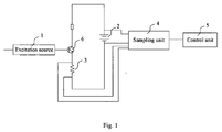
- an internal resistance testing device for testing an internal resistance of a battery pack comprises an excitation source 1 and a battery pack 2, an adjustable resistance 3, a sampling unit 4 and a control unit 5.
- the adjustable resistance 3 is connected with the battery pack 2 so as to form a loop circuit.
- the excitation source 1 is coupled to the loop circuit to apply an excitation to the loop circuit so as to generate an excitation current in the loop circuit.
- the sampling unit 4 is coupled to the loop circuit and used to collect an excitation voltage V 2 between two terminals of the battery pack 2, an excitation voltage V 1 between two terminals of the adjustable resistance 3 and a resistance value R of the adjustable resistance 3.
- the control unit 5 is coupled to the sampling unit 4 and used to calculate an internal resistance of the battery pack2 based on the excitation voltage V 2 , the excitation voltage V 1 and the resistance value R of the adjustable resistance 3 which are collected by the sampling unit 4 at a time when the excitation voltage V 2 is equal to a range voltage V (standard) of the sampling unit 4.
- the excitation source 1 may be an alternating current excitation source to apply an alternating current excitation to the loop circuit.
- the internal resistance testing device further comprises a transistor 6 connected in the loop circuit.
- the excitation source 1 is coupled to a control end of the transistor 6 so that the excitation source 1 may apply the alternating current excitation to the loop circuit via the control end of the transistor 6, so as to generate a sine excitation current in the loop circuit, so that an excitation voltage V 1 between two terminals of the adjustable resistance and an excitation voltage V 2 between two terminals of the battery pack 2.
- the sampling unit 4 is coupled to the loop circuit and used to collect the excitation voltage V 2 between two terminals of the battery pack 2, the excitation voltage V 1 between two terminals of the adjustable resistance 3 and the resistance value R of the adjustable resistance 3. After an alternating current excitation is applied to the loop circuit, excitation voltages between two terminals of the adjustable resistance 3 and between two terminals of the battery pack 2 may be generated respectively. Then the sampling unit 4 may collect excitation voltages between two terminals of the adjustable resistance 3 and between two terminals of the battery pack 1 as well as the resistance value R of the adjustable resistance 3.
- the sampling unit may be a CS5463 sampling chip.
- the control unit 5 may be coupled to the sampling unit 4 to receive the excitation voltage V 2 , the excitation voltage V 1 and the resistance value R of the adjustable resistance 3 which are collected by the sampling unit at a time when the excitation voltage V 2 is equal to a range voltage V (standard) of the sampling unit 4, and calculate the internal resistance of the battery pack 2 based on the excitation voltage V 2 , the excitation voltage V 1 and the resistance value R of the adjustable resistance 3.
- the control program of the control unit 5 may be integrated into the sampling chip.
- the battery pack 2 may comprise at least one single cell.
- the internal resistance testing device may comprises a resistance value adjusting unit coupled to the adjustable resistance 3, the resistance value adjusting unit may coarsely and finely adjust the resistance value R of the adjustable resistance 3.
- the resistance value adjusting unit is controlled to adjust the resistance value R of the adjustable resistance 3 by the control unit 5 based on a relationship of the excitation voltage V 2 between two terminals of the battery pack 2 with the range voltage V (stantard) of the sampling unit 4.
- the internal resistance testing method comprises the following steps:
- the excitation source may apply an alternating current excitation to the loop circuit formed by the adjustable resistance 3, the battery pack 2 and the transistor 6 via the control end of the transistor 6, so as to generate a sine excitation current in the whole loop circuit, therefore, an excitation voltage V 1 is generated between two terminals of the adjustable resistance 3 and an excitation voltage V 2 is generated between two terminals of the battery pack 2.
- the sampling unit 4 may collect the excitation voltage V 1 between two terminals of the adjustable resistance 3, the excitation voltage V 2 between two terminals of the battery pack 2 and the resistance value R of the adjustable resistance 3, and send the collected excitation voltage V 1 , the excitation voltage V 2 and the resistance value R to the control unit 5.
- the resistance value R of the adjustable resistance 3 is coarsely adjusted to equate the excitation voltage V 2 with the maximum range voltage V (standard) of the sampling unit 4, which indicates that a clipping may exist in the waves of the excitation voltage collected by the sampling unit 4.
- the sampling unit 4 may collect the excitation voltage between two terminals of the adjustable resistance3 , the excitation voltage between two terminals of the battery pack 2 and the resistance value R of the adjustable resistance, and send the collected the excitation voltage between two terminals of the adjustable resistance 3, the excitation voltage between two terminals of the battery pack 2 and the resistance value R of the adjustable resistance 3 to the control unit 5.
- the control unit 5 may compare the excitation voltage V 2 between two terminals of the battery pack 2 with the range voltage V (standard) .
- the sampling unit 4 may continuously collect the excitation voltage V 1 between two terminals of the adjustable resistance 3, the excitation voltage V 2 between two terminals of the battery pack 2 and the resistance value R of the adjustable resistance, and send the collected the excitation voltage V 1 between two terminals of the adjustable resistance 3, the excitation voltage V 2 between two terminals of the battery pack 2 and the resistance value R of the adjustable resistance 3 to the control unit 5.
- the control unit 5 may continuously compare the excitation voltage V 2 between two terminals of the battery pack 2 with the maximum range voltage V (standard) of the sampling unit 4. If V 2 is still equal to V (standard) , that is to say, a clipping may exist in the waves, the resistance value R of the adjustable resistance 3 is continuously increased until V 2 is smaller than V (standard) .
- V 2 is smaller than V (standard)
- fine adjustment of the adjustable resistance is performed to equate the excitation voltage between two terminals of the battery pack 2 collected by the sampling unit 4 with the maximum range voltage V (standard) of the sampling unit 4.
- the particular fine adjustment process is as follows.
- the control unit 5 records the resistance value of the adjustable resistance, by which the excitation voltage between two terminals of the battery pack 2 is equal to the range voltage V (standard) of the sampling unit for the last time, as R 1 , and then records the resistance value of the adjustable resistance, by which V2 is smaller than V (standard) , as R 2 . If the critical resistance value R of the adjustable resistance is R 0 when the actual excitation voltage between two terminals of the battery pack 2 is equal to the maximum range voltage of the sampling unit 4, the R 0 is taken in a range of R 1 to R 2 . Therefore the resistance value of the adjustable resistance is finely adjusted in the range of R 1 to R 2 .
- a is a minimum unit for finely adjusting the adjustable resistance 3
- m and n are integer variables set in the testing device.
- the adjustable resistance is adjusted to equate the resistance value R of the adjustable resistance with an average resistance value R 3 of R 1 and R 2 .
- the control unit 5 may compare the excitation voltage V 2a between two terminals of the battery pack 2 with V (standard) . If the excitation voltage V 2a is equal to V (standard) , the control unit 5 may control the process of the testing to go into the flow C, as shown in Fig. 4 . If the excitation voltage V 2a is smaller than V (standard) , the control unit 5 may control the process of testing to go into the flow D, as shown in Fig. 5 .
- the adjustable resistance is finely adjusted to equate the resistance value R of the adjustable resistance 3 with ( m +1) a .
- the sampling unit 4 may continuously collect the excitation voltage V 2c between two terminals of the battery pack 2 and send the excitation voltage V 2c to the control unit 5.
- the control unit 5 may take the resistance value R of the adjustable resistance 3 as (m+1)a, that is to say, in order to keep the excitation voltage between two terminals of the battery pack 2 to be equal to V (standard) , the resistance value R of the adjustable resistance 3 needs to be adjusted to ( m +1) a , so that the internal resistance of the battery pack 3 measured at this moment is most accurate. If the excitation voltage V 2c between two terminals of the battery pack 2 received by the control unit 5 is equal to V (standard) , the resistance value R of the adjustable resistance 3 is needed to be continuously increased.
- the adjustable resistance 3 is finely adjusted to equate the resistance value R of the adjustable resistance 3 with ( m +2) a , then the excitation voltage between two terminals of the battery pack 2 is continuously collected. If the excitation voltage between two terminals of the battery pack 2 is smaller than V (standard) , the resistance value R of the adjustable resistance is finally taken as ( m +2) a , that is to say, when the resistance value R of the adjustable resistance is adjusted to ( m +2) a , the measured internal resistance of the battery pack is most accurate.
- the resistance value of the adjustable resistance is finely adjusted to ( m -1) a , and the sampling unit 4 may continuously collect the excitation voltage V 2g between two terminals of the battery pack and send the excitation voltage V 2g to the control unit 5.
- the control unit 5 may take the resistance value R of the adjustable resistance as ( m -1) a , that is to say, in order to equate the excitation voltage between two terminals of the battery pack 2 with V (standard) , the resistance value of the adjustable resistance 3 needs to be adjusted to ( m -1) a , so that the internal resistance of the battery pack measured at this moment is most accurate. If the excitation voltage V 2g of the battery pack received by the control unit 5 is smaller than V (standard) , the resistance value R of the adjustable resistance 3 is continuously decreased.
- the adjustable resistance is finely adjusted to equate the resistance value of the adjustable resistance with (m-2)a, then the excitation voltage between two terminals of the battery pack is continuously collected. If the excitation voltage between two terminals of the battery pack 2 is equal to V (standard) when the resistance value of the adjustable resistance is ( m -2) a , the adjustable resistance is taken as ( m -2) a , that is to say, when the adjustable resistance is adjusted to ( m -2) a , the measured internal resistance of the battery pack is most accurate.
- the resistance value of the adjustable resistance is finely adjusted to (n-1)a, and the sampling unit 4 may continuously collect the excitation voltage V 2f between two terminals of the battery pack 2 and send the excitation voltage V 2f to the control unit 5. If the excitation voltage V 2f of the battery pack received by the control unit 5 is equal to V (standard) when the resistance value of the adjustable resistance is equal to (n-1)a, the control unit 5 may take the resistance value R of the adjustable resistance as ( n -1) a , that is to say, in order to equate the excitation voltage between two terminals of the battery pack with V (standard ), the resistance value of the adjustable resistance needs to be adjusted to (n-1)a, so that the internal resistance of the battery pack measured at this moment is most accurate.
- the resistance value R of the adjustable resistance is needed to be continuously decreased.
- the adjustable resistance 3 is finely adjusted to equate the resistance value of the adjustable resistance with (n-2)a, then the excitation voltage between two terminals of the battery pack is continuously collected. If the excitation voltage between two terminals of the battery pack is equal to V (standard) when the resistance value is equal to (n-2)a, the adjustable resistance is finally taken as (n-2)a, that is to say, when the adjustable resistance is adjusted to (n-2)a, the measured internal resistance of the battery pack is most accurate.
- the sampling unit 4 may continuously collect the excitation voltage V 2e between two terminals of the battery pack and send the excitation voltage V 2e to the control unit 5.
- the control unit 5 may take the resistance value R of the adjustable resistance as ( n +1) a , that is to say, in order to equate the excitation voltage between two terminals of the battery pack with V (standard) , the resistance value R of the adjustable resistance needs to be adjusted to ( n +1) a , so that the internal resistance of the battery pack measured at this moment is most accurate. If the excitation voltage V 2e between two terminals of the battery pack received by the control unit 5 is equal to V (standard) , the resistance value R of the adjustable resistance is needed to be continuously increased.
- the adjustable resistance is finely adjusted to equate the resistance value R of the adjustable resistance with ( n +2) a , then the excitation voltage between two terminals of the battery pack is continuously collected. If the excitation voltage between two terminals of the battery pack is smaller than V (standard) , the resistance value R of the adjustable resistance is finally taken as ( n +2) a , that is to say, when the resistance value R of the adjustable resistance is adjusted to ( n +2) a , the measured internal resistance of the battery pack is most accurate.
- the resistance value of the adjustable resistance may be adjusted manually or under control of inner program, for example the resistance value R of the adjustable resistance may be adjusted coarsely and finely by the resistance value adjusting unit.
Landscapes
- Engineering & Computer Science (AREA)
- Manufacturing & Machinery (AREA)
- Chemical & Material Sciences (AREA)
- Chemical Kinetics & Catalysis (AREA)
- Electrochemistry (AREA)
- General Chemical & Material Sciences (AREA)
- Physics & Mathematics (AREA)
- General Physics & Mathematics (AREA)
- Power Engineering (AREA)
- Secondary Cells (AREA)
Abstract
Description
- The present disclosure relates to device and method of testing an internal resistance of a battery pack, more particularly to device and method of testing the internal resistance of a battery pack used in an electric vehicle or a hybrid vehicle.
- The battery pack plays an important role in the electric vehicle and the hybrid vehicle. The battery pack system is generally connected in series. Deterioration of the status of some cells in the battery pack may affect the whole capability of the battery pack directly. That is, the whole capability of the battery pack is decided by the capability of one or more cells whose status is deteriorated most seriously. Therefore, it is necessary to accurately measure the status of each cell so as to avoid failure of the battery pack.
- Conventionally, the method of testing the internal resistance of the battery pack comprises a direct current discharge method and an alternating current injection method. The direct current discharge method comprises steps of generating an instant load current by a battery pack, then measuring the instant change of the voltage at the electrode pole of the battery pack and calculating the internal resistance of the battery pack.
- The disadvantages of the direct current discharge method are as follows.
- Because the remaining capability needs to be measured and displayed frequently, it is required to frequently measure the internal resistance, thereby influencing the normal running of the electric vehicle and reducing the remaining capability of the battery pack. Moreover, the number of the battery packs in the electric vehicle is large, which may greatly waste capability of the battery pack. The direct current discharge method is only suitable to measure the battery pack with large voltage range, because it is impossible to load the battery pack having small voltage range with a large current of about several ten ampere in a short period of time of several seconds. The electrodes in the battery pack may be damaged when the large current passes through the battery pack, thereby influencing the measurement accuracy. In addition, the direct current discharge method can not be used in the hybrid vehicle.
- The alternating current injection method comprises applying a constant alternating audio current source to two terminals of the battery pack, then detecting the excitation voltage between two terminals of the battery pack and the phase difference therebetween. The internal resistance of the battery pack may be obtained according to Ohm's law.
- In the alternating current injection method, the safe online detecting of the internal resistance of the battery pack may be realized without discharging of the battery pack, which may not influence the performance of the battery pack. However, similarly to the direct current discharge method, the alternating current injection method has the problem that the detected voltage range of the battery pack is limited. Moreover, the trigonometric function calculation needs to be performed in MCU (Microprogrammed Control Unit) for the alternating current injection method. Therefore, the hardware circuit and algorithm are quite complicated, thereby influencing the measurement accuracy.
- Document
US 2005/0218915 A1 discloses a method for testing electrochemical cells that applies a portion of a cycle of a low-frequency excitation waveform to a cell under test while maintaining an amplitude of the excitation waveform below a threshold value. - Document
US 3873911 discloses a self-contained electronic device for testing storage batteries by using a modified bridge circuit to determine the inverse dynamic resistance. - The present disclosure is directed to solve at least one problem existing in the prior art. Accordingly, device and method for testing an internal resistance of a battery pack having different voltage ranges are provided, thereby effectively improving the accuracy of measuring the internal resistance.
- According to an aspect of the disclosure, an internal resistance testing device is provided, which comprises a battery pack; an adjustable resistance connected with the battery pack to form a loop circuit; an excitation source coupled to the loop circuit to apply an excitation to the loop circuit so as to generate an excitation current in the loop circuit; a sampling unit coupled to the loop circuit and used to collect an excitation voltage V 2 between two terminals of the battery pack, an excitation voltage V 1, between two terminals of the adjustable resistance and a resistance value R of the adjustable resistance; and a control unit coupled to the sampling unit and used to calculate an internal resistance of the battery pack based on the excitation voltage V 2, the excitation voltage V 1 and the resistance value R which are collected by the sampling unit at a time when the excitation voltage V 2 is substantially equal to a range voltage V (standard) of the sampling unit.
- According to another aspect of the present disclosure, an internal resistance testing method using the internal resistance testing device according to the first aspect is provided. The method comprises steps of: a) applying an excitation to the loop circuit by the excitation source; b) collecting an excitation voltage V 2 between the two terminals of the battery pack, an excitation voltage V 1 between the two terminals of the adjustable resistance and the resistance value R of the adjustable resistance by the sampling unit; c) adjusting the resistance value R of the adjustable resistance to equate the excitation voltage V 2 between the two terminals of the battery pack with the range voltage V (standard) of the sampling unit; and d) calculating an internal resistance r of the battery pack based on the excitation voltage V 2, the excitation voltage V 1, and the resistance value R of the adjustable resistance which are collected at a time when the excitation voltage V 2 is substantially equal to a range voltage V (standard) of the sampling unit.
according to embodiments of the present embodiments, by adjusting the resistance value R of the adjustable resistance to equate the excitation voltage between two terminals of the adjustable resistance with the range voltage of the sampling unit, testing of the internal resistance of the battery pack having different voltage ranges may be achieved. Moreover, by adjusting the adjustable resistance, the adjustment of the current and the voltage in the loop circuit may be realized, so that the excitation voltage between two terminals of the adjustable resistance may be equal to the range voltage of the sampling unit. Therefore, the accuracy of measuring the internal resistance of the battery pack may be improved effectively. - Additional aspects and advantages of the embodiments of the present disclosure will be given in part in the following descriptions, become apparent in part from the following descriptions, or be learned from the practice of the embodiments of the present disclosure.
- These and other aspects and advantages of the disclosure will become apparent and more readily appreciated from the following descriptions taken in conjunction with the drawings in which:
-
Fig. 1 is a structural block diagram of the internal resistance testing device according to an embodiment of the present disclosure; -
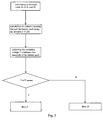
Fig. 2 is a flow chat of coarsely adjusting the adjustable resistance in the internal resistance testing method according to an embodiment of the present disclosure; -
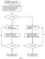
Fig. 3 is a flow chat of finely adjusting the adjustable resistance in the internal resistance testing method according to an embodiment of the present disclosure; -
Fig. 4 is a flow chart of flow C inFig. 3 ; and -
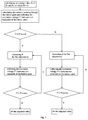
Fig. 5 is a flow chart of the flow D inFig.3 . - Reference will be made in detail to embodiments of the present disclosure. The embodiments described herein with reference to drawings are explanatory, illustrative, and used to generally understand the present disclosure. The embodiments shall not be construed to limit the present disclosure. The same or similar elements and the elements having same or similar functions are denoted by like reference numerals throughout the descriptions.
- As shown in
Fig. 1 , an internal resistance testing device for testing an internal resistance of a battery pack comprises anexcitation source 1 and abattery pack 2, anadjustable resistance 3, a sampling unit 4 and a control unit 5. Theadjustable resistance 3 is connected with thebattery pack 2 so as to form a loop circuit. Theexcitation source 1 is coupled to the loop circuit to apply an excitation to the loop circuit so as to generate an excitation current in the loop circuit. The sampling unit 4 is coupled to the loop circuit and used to collect an excitation voltage V 2 between two terminals of thebattery pack 2, an excitation voltage V 1 between two terminals of theadjustable resistance 3 and a resistance value R of theadjustable resistance 3. The control unit 5 is coupled to the sampling unit 4 and used to calculate an internal resistance of the battery pack2 based on the excitation voltage V 2, the excitation voltage V 1 and the resistance value R of theadjustable resistance 3 which are collected by the sampling unit 4 at a time when the excitation voltage V 2 is equal to a range voltage V (standard) of the sampling unit 4. - In some embodiments, the
excitation source 1 may be an alternating current excitation source to apply an alternating current excitation to the loop circuit. - In some embodiments, as shown in
Fig. 1 , The internal resistance testing device further comprises atransistor 6 connected in the loop circuit. Theexcitation source 1 is coupled to a control end of thetransistor 6 so that theexcitation source 1 may apply the alternating current excitation to the loop circuit via the control end of thetransistor 6, so as to generate a sine excitation current in the loop circuit, so that an excitation voltage V1 between two terminals of the adjustable resistance and an excitation voltage V2 between two terminals of thebattery pack 2. - The sampling unit 4 is coupled to the loop circuit and used to collect the excitation voltage V2 between two terminals of the
battery pack 2, the excitation voltage V 1 between two terminals of theadjustable resistance 3 and the resistance value R of theadjustable resistance 3. After an alternating current excitation is applied to the loop circuit, excitation voltages between two terminals of theadjustable resistance 3 and between two terminals of thebattery pack 2 may be generated respectively. Then the sampling unit 4 may collect excitation voltages between two terminals of theadjustable resistance 3 and between two terminals of thebattery pack 1 as well as the resistance value R of theadjustable resistance 3. In an embodiment, the sampling unit may be a CS5463 sampling chip. - The control unit 5 may be coupled to the sampling unit 4 to receive the excitation voltage V 2, the excitation voltage V 1 and the resistance value R of the
adjustable resistance 3 which are collected by the sampling unit at a time when the excitation voltage V 2 is equal to a range voltage V (standard) of the sampling unit 4, and calculate the internal resistance of thebattery pack 2 based on the excitation voltage V 2, the excitation voltage V 1 and the resistance value R of theadjustable resistance 3. In an embodiment, the control program of the control unit 5 may be integrated into the sampling chip. Thebattery pack 2 may comprise at least one single cell. - Particularly, the control unit 5 calculates the internal resistance of the
battery pack 2 using a formula: r=PF × V 2/I, in which r is the internal resistance of thebattery pack 2, I is an excitation current in the loop circuit and calculated by using the excitation voltage V2 between two terminals of theadjustable resistance 3 and the resistance value R of the adjustable resistance, and PF is a power coefficient of the loop circuit. - In some embodiment, the internal resistance testing device may comprises a resistance value adjusting unit coupled to the
adjustable resistance 3, the resistance value adjusting unit may coarsely and finely adjust the resistance value R of theadjustable resistance 3. For example, the resistance value adjusting unit is controlled to adjust the resistance value R of theadjustable resistance 3 by the control unit 5 based on a relationship of the excitation voltage V 2 between two terminals of thebattery pack 2 with the range voltage V (stantard) of the sampling unit 4. - An internal resistance testing method using the internal resistance testing device according to embodiments of the present disclosure will be described below.
- The internal resistance testing method comprises the following steps:
- a) applying an excitation to the loop circuit by the
excitation source 1; - b) collecting an excitation voltage V 2 between the two terminals of the
battery pack 2, an excitation voltage V 1 between the two terminals of theadjustable resistance 3 and the resistance value R of theadjustable resistance 3 by the sampling unit 4; - c) adjusting the resistance value R of the
adjustable resistance 3 to equate the excitation voltage V2 between the two terminals of thebattery pack 2 with the range voltage V (standard) of the sampling unit 4; and - d) calculating an internal resistance r of the battery pack based on the excitation voltage V 2, the excitation voltage V 1 and the resistance value R which are collected by the sampling unit 4 at a time when the excitation voltage V 2 is equal to a range voltage V (standard) of the sampling unit 4.
- In some particular embodiments of the present disclosure, as shown in
Fig. 2 andFig. 3 , firstly, the excitation source may apply an alternating current excitation to the loop circuit formed by theadjustable resistance 3, thebattery pack 2 and thetransistor 6 via the control end of thetransistor 6, so as to generate a sine excitation current in the whole loop circuit, therefore, an excitation voltage V 1 is generated between two terminals of theadjustable resistance 3 and an excitation voltage V 2 is generated between two terminals of thebattery pack 2. - At this time, the sampling unit 4 may collect the excitation voltage V 1 between two terminals of the
adjustable resistance 3, the excitation voltage V 2 between two terminals of thebattery pack 2 and the resistance value R of theadjustable resistance 3, and send the collected excitation voltage V 1, the excitation voltage V 2 and the resistance value R to the control unit 5. - The resistance value R of the
adjustable resistance 3 is coarsely adjusted to equate the excitation voltage V 2 with the maximum range voltage V (standard) of the sampling unit 4, which indicates that a clipping may exist in the waves of the excitation voltage collected by the sampling unit 4. - Then the
adjustable resistance 3 is coarsely adjusted to increase the resistance value R of theadjustable resistance 3, and the sampling unit 4 may collect the excitation voltage between two terminals of the adjustable resistance3 , the excitation voltage between two terminals of thebattery pack 2 and the resistance value R of the adjustable resistance, and send the collected the excitation voltage between two terminals of theadjustable resistance 3, the excitation voltage between two terminals of thebattery pack 2 and the resistance value R of theadjustable resistance 3 to the control unit 5. The control unit 5 may compare the excitation voltage V 2 between two terminals of thebattery pack 2 with the range voltage V (standard). - If V 2=V (standard), that is to say, a clipping may exist in the waves, coarse adjustment of the
adjustable resistance 3 is continued to increase the resistance value R of theadjustable resistance 3, so that the excitation current in the loop circuit may be decreased. The sampling unit 4 may continuously collect the excitation voltage V1 between two terminals of theadjustable resistance 3, the excitation voltage V2 between two terminals of thebattery pack 2 and the resistance value R of the adjustable resistance, and send the collected the excitation voltage V1 between two terminals of theadjustable resistance 3, the excitation voltage V2 between two terminals of thebattery pack 2 and the resistance value R of theadjustable resistance 3 to the control unit 5. The control unit 5 may continuously compare the excitation voltage V 2 between two terminals of thebattery pack 2 with the maximum range voltage V (standard) of the sampling unit 4. If V 2 is still equal to V (standard), that is to say, a clipping may exist in the waves, the resistance value R of theadjustable resistance 3 is continuously increased until V 2 is smaller than V (standard). - If V 2 is smaller than V (standard), fine adjustment of the adjustable resistance is performed to equate the excitation voltage between two terminals of the
battery pack 2 collected by the sampling unit 4 with the maximum range voltage V (standard) of the sampling unit 4. The particular fine adjustment process is as follows. - During the coarse adjustment of the adjustable resistance, the control unit 5 records the resistance value of the adjustable resistance, by which the excitation voltage between two terminals of the
battery pack 2 is equal to the range voltage V (standard) of the sampling unit for the last time, as R 1, and then records the resistance value of the adjustable resistance, by which V2 is smaller than V (standard), as R 2. If the critical resistance value R of the adjustable resistance is R 0 when the actual excitation voltage between two terminals of thebattery pack 2 is equal to the maximum range voltage of the sampling unit 4, the R 0 is taken in a range of R 1 to R 2. Therefore the resistance value of the adjustable resistance is finely adjusted in the range of R 1 to R 2. - In a particular embodiment, a is a minimum unit for finely adjusting the
adjustable resistance 3, and m and n are integer variables set in the testing device. - During the fine adjustment, the adjustable resistance is adjusted to equate the resistance value R of the adjustable resistance with an average resistance value R 3 of R 1 and R 2. The control unit 5 may calculate the current in the loop circuit using the formula I=V 1/R 3 based on the excitation voltage V 1 between two terminals of the
adjustable resistance 3 and the resistance value R3 of the adjustable resistance collected by the sampling unit 4. After collecting the excitation voltage V 2a between two terminals of thebattery pack 2, the sampling unit 4 may send the excitation voltage V 2a to the control unit 5. - The control unit 5 may compare the excitation voltage V 2a between two terminals of the
battery pack 2 with V (standard). If the excitation voltage V 2a is equal to V (standard), the control unit 5 may control the process of the testing to go into the flow C, as shown inFig. 4 . If the excitation voltage V 2a is smaller than V (standard), the control unit 5 may control the process of testing to go into the flow D, as shown inFig. 5 . - As shown in
Fig. 4 , when the process of the testing enters into flow C, because the excitation voltage V 2a between two terminals of thebattery pack 2 is equal to V (standard), R 3<R 0, so that the resistance value R of theadjustable resistance 3 needs to be increased. The adjustable resistance is adjusted to equate the resistance value R of the adjustable resistance with an average resistance value R5 of R 2 and R 3, in which R5 =ma. The control unit 5 may calculate the current in the loop circuit using the formula I=V 1/R 5 based on the excitation voltage V 1 between two terminals of theadjustable resistance 3 and the resistance value R5 of theadjustable resistance 3 collected by the sampling unit 4, and the excitation voltage V 2b between two terminals of thebattery pack 2 is collected by the sampling unit 4 and sent to the control unit 5. If the excitation voltage V 2b between two terminals of thebattery pack 2 collected by the sampling unit 4 is still equal to V (standard), R 5<R 0, then keeping on increasing the resistance value R of theadjustable resistance 3. - The adjustable resistance is finely adjusted to equate the resistance value R of the
adjustable resistance 3 with (m+1)a. The sampling unit 4 may continuously collect the excitation voltage V 2c between two terminals of thebattery pack 2 and send the excitation voltage V 2c to the control unit 5. If the excitation voltage V2c between two terminals of thebattery pack 2 collected by the control unit 4 is smaller than V (standard) at this moment, the control unit 5 may take the resistance value R of theadjustable resistance 3 as (m+1)a, that is to say, in order to keep the excitation voltage between two terminals of thebattery pack 2 to be equal to V (standard), the resistance value R of theadjustable resistance 3 needs to be adjusted to (m+1)a, so that the internal resistance of thebattery pack 3 measured at this moment is most accurate. If the excitation voltage V 2c between two terminals of thebattery pack 2 received by the control unit 5 is equal to V (standard), the resistance value R of theadjustable resistance 3 is needed to be continuously increased. Theadjustable resistance 3 is finely adjusted to equate the resistance value R of theadjustable resistance 3 with (m+2)a, then the excitation voltage between two terminals of thebattery pack 2 is continuously collected. If the excitation voltage between two terminals of thebattery pack 2 is smaller than V (standard), the resistance value R of the adjustable resistance is finally taken as (m+2)a, that is to say, when the resistance value R of the adjustable resistance is adjusted to (m+2)a, the measured internal resistance of the battery pack is most accurate. Otherwise, the resistance value of the adjustable resistance is continuously increased by the minimum unit through the fine adjustment, until the resistance value R of the adjustable resistance satisfies that the excitation voltage between two terminals of the battery pack is equal to V (standard) when R=(m+x-1)a, in which x is a number of times of fine adjustment, and the excitation voltage between two terminals of the battery pack is smaller than V (standard) when R=(m+x)a. Therefore, only when the resistance value R of the adjustable resistance is adjusted to (m+x)a, the excitation voltage between two terminals of the battery pack is equal to V (standard), and the measured internal resistance of the battery pack at this moment is most accurate. - If the excitation voltage V 2b between two terminals of the
battery pack 2 collected by the sampling unit 4 is smaller than V (standard), R 5>R 0, so that the resistance value R of the adjustable resistance needs to be decreased. The resistance value of the adjustable resistance is finely adjusted to (m-1)a, and the sampling unit 4 may continuously collect the excitation voltage V 2g between two terminals of the battery pack and send the excitation voltage V 2g to the control unit 5. If the excitation voltage V 2g of thebattery pack 2 received by the control unit 5 is equal to V (standard) when the resistance value of the adjustable resistance is (m-1)a, the control unit 5 may take the resistance value R of the adjustable resistance as (m-1)a, that is to say, in order to equate the excitation voltage between two terminals of thebattery pack 2 with V (standard), the resistance value of theadjustable resistance 3 needs to be adjusted to (m-1)a, so that the internal resistance of the battery pack measured at this moment is most accurate. If the excitation voltage V 2g of the battery pack received by the control unit 5 is smaller than V (standard), the resistance value R of theadjustable resistance 3 is continuously decreased. The adjustable resistance is finely adjusted to equate the resistance value of the adjustable resistance with (m-2)a, then the excitation voltage between two terminals of the battery pack is continuously collected. If the excitation voltage between two terminals of thebattery pack 2 is equal to V (standard) when the resistance value of the adjustable resistance is (m-2)a, the adjustable resistance is taken as (m-2)a, that is to say, when the adjustable resistance is adjusted to (m-2)a, the measured internal resistance of the battery pack is most accurate. Otherwise, the resistance value R of the adjustable resistance is continuously decreased by the minimum unit through the fine adjustment, until the resistance value R of the adjustable resistance satisfies that the excitation voltage between two terminals of the battery pack is equal to V (standard) when R=(m-z-1)a, in which z is a number of times of fine adjustment, and the excitation voltage between two terminals of the battery pack is smaller than V (standard) when R=(m-z)a. So that only when the resistance value R of theadjustable resistance 3 is adjusted to (m-z-1)a, the excitation voltage between two terminals of the battery pack is equal to V (standard), and the internal resistance of the battery pack measured at this moment is most accurate. - As shown in
Fig. 5 , when the process of testing enters into flow D, because the excitation voltage V 2a between two terminals of the battery pack is smaller than V (standard) at this moment , R 3>R 0, so that the resistance value R of theadjustable resistance 3 needs to be decreased. The adjustable resistance is adjusted to equate the resistance value R of the adjustable resistance with an average resistance value R4 of R 1 and R 3, in which R 4=na. The control unit 5 may calculate the current in the loop circuit using the formula I=V 1/R 4 based on the excitation voltage V 1 between two terminals of the adjustable resistance and the resistance value R4 of the adjustable resistance collected by the sampling unit 4, and the excitation voltage V 2d between two terminals of the battery pack is collected by the sampling unit 4 and sent to the control unit 5. If the excitation voltage V 2d between two terminals of the battery pack collected by the sampling unit 4 is still smaller than V (standard), R 3>R 0, it is needed to keeping on decreasing the resistance value R of theadjustable resistance 3. - The resistance value of the adjustable resistance is finely adjusted to (n-1)a, and the sampling unit 4 may continuously collect the excitation voltage V 2f between two terminals of the
battery pack 2 and send the excitation voltage V 2f to the control unit 5. If the excitation voltage V 2f of the battery pack received by the control unit 5 is equal to V (standard) when the resistance value of the adjustable resistance is equal to (n-1)a, the control unit 5 may take the resistance value R of the adjustable resistance as (n-1)a, that is to say, in order to equate the excitation voltage between two terminals of the battery pack with V (standard), the resistance value of the adjustable resistance needs to be adjusted to (n-1)a, so that the internal resistance of the battery pack measured at this moment is most accurate. If the excitation voltage V 2f of the battery pack received by the control unit 5 is smaller than V (standard), the resistance value R of the adjustable resistance is needed to be continuously decreased. Theadjustable resistance 3 is finely adjusted to equate the resistance value of the adjustable resistance with (n-2)a, then the excitation voltage between two terminals of the battery pack is continuously collected. If the excitation voltage between two terminals of the battery pack is equal to V (standard) when the resistance value is equal to (n-2)a, the adjustable resistance is finally taken as (n-2)a, that is to say, when the adjustable resistance is adjusted to (n-2)a, the measured internal resistance of the battery pack is most accurate. Otherwise, the resistance value R of the adjustable resistance is continuously decreased by the minimum unit through the fine adjustment until the resistance value R of the adjustable resistance satisfies that the excitation voltage between two terminals of the battery pack is equal to V (standard) when R=(n-y-1)a, in which y is a number of times of fine adjustment, and the excitation voltage between two terminals of the battery pack is smaller than V (standard) when R=(n-y)a. So that only when the resistance value R of the adjustable resistance is adjusted to (n-y-1)a, the excitation voltage between two terminals of the battery pack is equal to V (standard), and the internal resistance of the battery pack measured at this moment is most accurate. - If the excitation voltage V 2d between two terminals of the battery pack collected by the sampling unit 4 is equal to V (standard), R 3<R 0, so that the resistance value R of the adjustable resistance needs to be increased. The adjustable resistance is finely adjusted to equate the resistance value R of the adjustable resistance with (n+1)a. The sampling unit 4 may continuously collect the excitation voltage V 2e between two terminals of the battery pack and send the excitation voltage V 2e to the control unit 5. If the excitation voltage V 2e between two terminals of the battery pack received by the control unit 5 is smaller than V (standard) when the resistance value R of the adjustable resistance is equal to (n+1)a, the control unit 5 may take the resistance value R of the adjustable resistance as (n+1)a, that is to say, in order to equate the excitation voltage between two terminals of the battery pack with V (standard), the resistance value R of the adjustable resistance needs to be adjusted to (n+1)a, so that the internal resistance of the battery pack measured at this moment is most accurate. If the excitation voltage V2e between two terminals of the battery pack received by the control unit 5 is equal to V (standard), the resistance value R of the adjustable resistance is needed to be continuously increased. The adjustable resistance is finely adjusted to equate the resistance value R of the adjustable resistance with (n+2)a, then the excitation voltage between two terminals of the battery pack is continuously collected. If the excitation voltage between two terminals of the battery pack is smaller than V (standard), the resistance value R of the adjustable resistance is finally taken as (n+2)a, that is to say, when the resistance value R of the adjustable resistance is adjusted to (n+2)a, the measured internal resistance of the battery pack is most accurate. Otherwise, the resistance value of the adjustable resistance is continuously adjusted by the minimum unit through the fine adjustment until the resistance value R of the adjustable resistance satisfies that the excitation voltage between two terminals of the battery pack is equal to V (standard) when R=(n+w-1)a, in which w is a number of times of fine adjustment, and the excitation voltage between two terminals of the battery pack is smaller than V (standard) when R=(n+w)a. So that only when the resistance value R of the adjustable resistance is adjusted to (n+w)a, the internal resistance of the battery pack measured at this moment is most accurate.
- After the coarse and fine adjustment of the adjustable resistance, the control unit 5 may calculate the current in the loop circuit using the formula I=V 1/R based on the excitation voltage V 1 between two terminals of the adjustable resistance. Then the control unit 5 may calculate the internal resistance based on the excitation voltage V 2 between two terminals of the battery pack collected by the sampling unit 4 and the current I in the loop circuit. During applying the alternating current excitation, there is a phase difference between the excitation voltage and the excitation current, i.e. the power coefficient PF, so that the internal resistance of the battery pack r=PF×V 2 lI, in which the power coefficient PF may be calculated by the control unit 5, which is well known in the art and detailed description thereof is omitted here.
- In the above embodiments, the resistance value of the adjustable resistance may be adjusted manually or under control of inner program, for example the resistance value R of the adjustable resistance may be adjusted coarsely and finely by the resistance value adjusting unit.
- Although explanatory embodiments have been shown and described, it would be appreciated by those skilled in the art that changes, alternatives, and modifications can be made in the embodiments without departing from principles of the disclosure. Such changes, alternatives, and modifications all fall into the scope of the claims and their equivalents.
- According to further embodiments of the present invention the following exemplary embodiments are provided. These exemplary embodiments are denoted as examples "E".
- E1. An internal resistance testing device, comprising:
- a battery pack;
- an adjustable resistance connected with the battery pack to form a loop circuit;
- an excitation source coupled to the loop circuit to apply an excitation to the loop circuit so as to generate an excitation current in the loop circuit;
- a sampling unit coupled to the loop circuit and used to collect an excitation voltage V 2 between two terminals of the battery pack, an excitation voltage V 1 between two terminals of the adjustable resistance and a resistance value R of the adjustable resistance; and
- a control unit coupled to the sampling unit and used to calculate an internal resistance of the battery pack based on the excitation voltage V 2, the excitation voltage V 1 and the resistance value R which are collected by the sampling unit at a time when the excitation voltage V 2 is substantially equal to a range voltage V (standard) of the sampling unit.
- E2. The device according to E1, wherein the sampling unit is a CS5463 sampling chip.
- E3. The device according to E1, wherein the excitation source is an alternating current excitation source.
- E4. The device according to E1, further comprising a transistor connected in the loop circuit, in which the excitation source is coupled to a control end of the transistor to apply the excitation to the loop circuit via the transistor.
- E5. The device according to E1, wherein the control unit calculates the internal resistance of the battery pack using a formula: r=PF×V 2/I, in which r is the internal resistance of the battery pack, I is an excitation current in the loop circuit and calculated by using the excitation voltage V2 between two terminals of the adjustable resistance and the resistance value R of the adjustable resistance, and PF is a power coefficient of the loop circuit.
- E6. The device according to E1, further comprising:
- a resistance value adjusting unit coupled to the adjustable resistance and used to coarsely and finely adjust the resistance value R of the adjustable resistance.
- E7. The device according to E6, wherein the resistance value adjusting unit is controlled to adjust the resistance value R of the adjustable resistance by the control unit based on a relationship of the excitation voltage V 2 between two terminals of the battery pack with the range voltages. V (standard) of the sampling unit.
- E8. An internal resistance testing method using the internal resistance testing device according to E1, comprising steps of:
- a) applying an excitation to the loop circuit by the excitation source;
- b) collecting an excitation voltage V 2 between the two terminals of the battery pack, an excitation voltage V 1 between the two terminals of the adjustable resistance and the resistance value R of the adjustable resistance by the sampling unit;
- c) adjusting the resistance value R of the adjustable resistance to equate the excitation voltage V2 between the two terminals of the battery pack with the range voltage V (standard) of the sampling unit; and
- d) calculating an internal resistance r of the battery pack based on the excitation voltage V 2, the excitation voltage V 1 and the resistance value R which are collected at a time when the excitation voltage V 2 is substantially equal to a range voltage V (standard) of the sampling unit.
- E9. The method according to E8, wherein step c) comprises:
- coarsely adjusting the resistance value R of the adjustable resistance until the excitation voltage V 2 between two terminals of the battery pack collected by the sampling unit is substantially equal to the range voltage V (standard) of the sampling unit;
- increasing the resistance value R of the adjustable resistance until the excitation voltage V2 between two terminals of the battery pack collected by the sampling unit is smaller than the range voltage V (standard) of the sampling unit, and recording the resistance value of the adjustable resistance at this time as R 2;
- recording the resistance value of the adjustable resistance, by which the excitation voltage V2 between two terminals of the battery pack is substantially equal to the range voltage V (standard) of the sampling unit for the last time, as R 1;
- finely adjusting the adjustable resistance to substantially equate the excitation voltage V2 between two terminals of the battery pack with the range voltage of the sampling unit; and
- calculating the internal resistance of the battery pack based on the excitation voltage V 1 between two terminals of the adjustable resistance, the resistance value R of the adjustable resistance and the excitation voltage V 2 between two terminals of the battery pack which are collected at a time when the adjustable resistance is finely adjusted to substantially equate the excitation voltage V2 between two terminals of the battery pack with the range voltage V (standard) of the sampling unit.
- E10. The method according to E9, wherein finely adjusting the adjustable resistance comprises:
- adjusting the adjustable resistance to equate the resistance value R of the adjustable resistance with an average resistance value R3 of R 1 and R 2;
- collecting the excitation voltage V 2a between two terminals of the battery pack when the resistance value R of the adjustable resistance is equal to the average resistance value R3; and
- adjusting the resistance value R of the adjustable resistance based on the excitation voltage between two terminals of the battery pack and the range voltage V (standard) of the sampling unit.
- E11. The method according to E10, wherein adjusting the resistance value R of the adjustable resistance based on the excitation voltage V 2a between two terminals of the battery pack and the range voltage V (standard) of the sampling unit comprises:
- if the excitation voltage V 2a between two terminals of the battery pack is equal to V (standard),
- adjusting the adjustable resistance to equate the resistance value R of the adjustable resistance with an average resistance value R5 of R 2 and R 3, in which R 5=ma, where m is an integer variable set in the testing device, and a is a minimum unit for finely adjusting the adjustable resistance;
- collecting the excitation voltage V 2b between two terminals of the battery pack when the resistance value R is equal to average resistance value R5 ; and
- keeping on adjusting the resistance value R of the adjustable resistance based on the excitation voltage V 2b between two terminals of the battery pack and the range voltage V (standard) of the sampling unit.
- E12. The method according to E11, wherein keeping on adjusting the resistance value R of the adjustable resistance based on the excitation voltage V 2b between two terminals of the battery pack and the range voltage V (standard) of the sampling unit further comprises:
- if the excitation voltage V 2b between two terminals of the battery pack is equal to V (standard),
- adjusting the adjustable resistance to equate the resistance value R of the adjustable resistance with (m+1)a;
- determining whether the excitation voltage V 2c between two terminals of the battery pack is smaller than V (standard) when the resistance value R of the adjustable resistance is equal to (m+1)a; and
- if V 2c<V (standard), taking the resistance value R of the adjustable resistance as (m+1)a, and calculating the internal resistance of the battery pack based on the excitation voltage between two terminals of the battery pack, the excitation voltage between two terminals of the adjustable resistance and the resistance value of the adjustable resistance which are collected by the sampling unit at a time when V 2c<V (standard) and the resistance value R of the adjustable resistance is taken as (m+1)a.
- E13. The method according to E12, further comprising:
- if V 2c=V (standard), keeping on adjusting the resistance value R of the adjustable resistance; and
- when the resistance value R of the adjustable resistance satisfies that the excitation voltage between two terminals of the battery pack is equal to V (standard) when R=(m+x-1)a, in which x is a number of times of fine adjustment, and the excitation voltage between two terminals of the battery pack is smaller than V (standard) when R=(m+x)a, taking the resistance value R of the adjustable resistance as (m+x)a, and calculating the internal resistance of the battery pack based on the excitation voltage between two terminals of the battery pack, the excitation voltage between two terminals of the adjustable resistance and the resistance value of the adjustable resistance which are collected by the sampling unit at a time when V 2c= V (standard) and the resistance value R of the adjustable resistance is taken as (m+x)a.
- E14. The method according to E11, wherein keeping on adjusting the resistance value of the adjustable resistance based on the excitation voltage V 2b between two terminals of the battery pack and the range voltage V (standard) of the sampling unit further comprises:
- if the excitation voltage V 2b between two terminals of the battery pack is smaller than V (standard) of the sampling unit,
- keeping on adjusting the adjustable resistance to equate the resistance value R of the adjustable resistance with (m-1)a;
- determining whether the excitation voltage V 2g between two terminals of the battery pack is equal to V (standard) when the resistance value R of the adjustable resistance is equal to (m-1)a; and
- if V 2g=V (standard), taking the adjustable resistance as (m-1)a, and calculating the internal resistance of the battery pack based on the excitation voltage between two terminals of the battery pack, the excitation voltage between two terminals of the adjustable resistance and the resistance value of the adjustable resistance which are collected by the sampling unit at a time when V 2g=V (standard) and the resistance value R is taken as (m-1)a.
- 15. The method according to claim 14, further comprising:
- if V 2a<V (standard), keeping on adjusting the resistance value R of the adjustable resistance; and
- When the resistance value R of the adjustable resistance satisfies that the excitation voltage between two terminals of the battery pack is equal to V (standard) when R=(m-z-1)a, in which z is a number of times of fine adjustment, and the excitation voltage between two terminals of the battery pack is smaller than V (standard) when R=(m-z)a, taking the resistance value R of the adjustable resistance as (m-z-1)a, and calculating the internal resistance of the battery pack based on the excitation voltage between two terminals of the battery pack, the excitation voltage between two terminals of the adjustable resistance and the resistance value of the adjustable resistance which are collected by the sampling unit at a time when V 2g<V (standard) and the resistance value R of the adjustable resistance is taken as (m-z-1)a.
- E16. The method according to E10, wherein adjusting the resistance value of the adjustable resistance based on the excitation voltage V 2a, between two terminals of the battery pack and the range voltage V (Standard) of the sampling unit comprises:
- if the excitation voltage V 2a between two terminals of the battery pack is smaller than V (standard),
- adjusting the adjustable resistance to equate the resistance value R of the adjustable resistance with an average resistance value R4 of R 1 and R 3, in which R 4=na, where n is an integer variable set in the testing device, and a is a minimum unit for finely adjusting the adjustable resistance;
- collecting the excitation voltage V 2d between two terminals of the battery pack; and
- keeping on adjusting the resistance value R of the adjustable resistance based on the excitation voltage V 2d between two terminals of the battery pack and the range voltage V (stdndard) of the sampling unit.
- E17. The method according to E16, wherein keeping on adjusting the resistance value of the adjustable resistance based on the excitation voltage V 2d between two terminals of the battery pack and the range voltage V (standard) of the sampling unit further comprises:
- if the excitation voltage V 2d between two terminals of the battery pack is equal to V (standard),
- adjusting the adjustable resistance to equate the resistance value R of the adjustable resistance with (n+1)a;
- determining whether the excitation voltage V 2e between two terminals of the battery pack is smaller than V (standard) when the resistance value R of the adjustable resistance is equal to (n+1)a; and
- if V 2e<V (standard), taking the adjustable resistance as (n+1)a, and calculating the internal resistance of the battery pack based on the excitation voltage between two terminals of the battery pack, the excitation voltage between two terminals of the adjustable resistance and the resistance value of the adjustable resistance which are collected by the sampling unit at a time when V 2e<V (standard) and the resistance value R of the adjustable resistance is taken as (n+1)a.
- E 18. The method according to E17, further comprising:
- if V 2e=V (standard), keeping on adjusting the resistance value R of the adjustable resistance; and
- when the resistance value R of the adjustable resistance satisfies that the excitation voltage between two terminals of the battery pack is equal to V (standard) when R=(n+w-1)a, in which w is a number of times of fine adjustment, and the excitation voltage between two terminals of the battery pack is smaller than V (standard) when R=(n+w)a, taking the resistance value of the adjustable resistance as (n+w)a, and calculating the internal resistance of the battery pack based on the excitation voltage between two terminals of the battery pack, the excitation voltage between two terminals of the adjustable resistance and the resistance value of the adjustable resistance which are collected by the sampling unit at a time when V 2e=V (standard) and the resistance value R of the adjustable resistance is taken as (n+w)a.
- E19. The method according to E16, wherein keeping on adjusting the resistance value of the adjustable resistance based on the excitation voltage V 2d between two terminals of the battery pack and the range voltage V (standard) of the sampling unit further comprises:
- if the excitation voltage V 2d between two terminals of the battery pack collected by the sample unit is smaller than V (standard),
- adjusting the adjustable resistance to equate the resistance value R of the adjustable resistance with (n-1)a;
- determining whether the excitation voltage V 2f between two terminals of the battery pack is equal to V (standard) when the resistance value R of the adjustable resistance to be equal to (n-1)a; and
- if V 2f=V (standard), taking the resistance value R of the adjustable resistance as (n-1)a, and calculating the internal resistance of the battery pack based on the excitation voltage between two terminals of the battery pack, the excitation voltage between two terminals of the adjustable resistance and the resistance value of the adjustable resistance which are collected by the sampling unit at a time when V 2f=V (standard) and the resistance value R of the adjustable resistance is taken as (n-1)a.
- E20. The method according to E19, further comprising:
- if V 2f<V (standard), keeping on adjusting the resistance value R of the adjustable resistance; and
- when the resistance value R of the adjustable resistance satisfies that the excitation voltage between two terminals of the battery pack is equal to V (standard) when R=(n-y-1)a, in which y is a number of times of fine adjustment, and the excitation voltage between two terminals of the battery pack is smaller than V (standard) when R=(n-y)a, taking the resistance value of the adjustable resistance as (n-y-1)a, and calculating the internal resistance of the battery pack based on the excitation voltage between two terminals of the battery pack, the excitation voltage between two terminals of the adjustable resistance and the resistance value of the adjustable resistance which are collected by the sampling unit at a time when the resistance value R of the adjustable resistance is taken as (n-y-1)a.
- E21. The method according to E8, wherein the internal resistance of the battery pack is calculated by the control unit using a formula: r=PF×V 2/I, in which I is the excitation current in the loop circuit and is calculated by the excitation voltage between two terminals of the adjustable resistance and the resistance value of the adjustable resistance, and PF is a power coefficient of the loop circuit.
Claims (15)
- An internal resistance testing device, comprising:a battery pack (2),an adjustable resistance (3) connected with the battery pack (2) to form a loop circuit;an excitation source (11) coupled to the loop circuit to apply an excitation to the loop circuit so as to generate an excitation current in the loop circuit;a sampling unit (4) coupled to the loop circuit and used to collect an excitation voltage V 2 between two terminals of the battery pack (2), an excitation voltage V 1 between two terminals of the adjustable resistance (3) and a resistance value R of the adjustable resistance (3), anda control unit (5) coupled to the sampling unit (4) and used to calculate an internal resistance of the battery pack (2) based on the excitation voltage V 2, the excitation voltage V 1 and the resistance value R which are collected by the sampling unit (4) at a time when the excitation voltage V 2 is substantially equal to a range voltage V (standard) of the sampling unit (4).
- The device according to claim 1, wherein eitheri) the sampling unit is a CS5463 sampling chip; orii) the excitation source is an alternating current excitation source; oriii) the device further comprises a transistor connected in the loop circuit, in which the excitation source is coupled to a control end of the transistor to apply the excitation to the loop circuit via the transistor.
- The device according to claim 1, wherein the control unit calculates the internal resistance of the battery pack using a formula: r=PF × V 2/I, in which r is the internal resistance of the battery pack. I is an excitation current in the loop circuit and calculated by using the excitation voltage V2 between two terminals of the adjustable resistance and the resistance value R of the adjustable resistance, and PF is a power coefficient of the loop circuit.
- The device according to claim 1, further comprising:a resistance value adjusting unit coupled to the adjustable resistance and used to coarsely and finely adjust the resistance value R of the adjustable resistance.
- The device according to claim 4, wherein the resistance value adjusting unit is controlled to adjust the resistance value R of the adjustable resistance by the control unit based on a relationship of the excitation voltage V 2 between two terminals of the battery pack with the range voltage V (standard) of the sampling unit.
- An internal resistance testing method using the internal resistance testing device according to claim 1, comprising steps of:a) applying an excitation to the loop circuit by the excitation source (1);b) collecting an excitation voltage V 2 between the two terminals of the battery pack (2), an excitation voltage V 1 between the two terminals of the adjustable resistance (3) and the resistance value R of the adjustable resistance (3) by the sampling unit (4);c) adjusting the resistance value R of the adjustable resistance (3) to equate the excitation voltage V2 between the two terminals of the battery pack (2) with the range voltage V (standard) of the sampling unit (4); andd) calculating an internal resistance r of the battery pack based on the excitation voltage V 2, the excitation voltage V 1 and the resistance value R which are collected at a time when the excitation voltage V 2 is substantially equal to a range voltage V (standard) of the sampling unit (4).
- The method according to claim 6, wherein step c) comprises:coarsely adjusting the resistance value R of the adjustable resistance until the excitation voltage V2 between two terminals of the battery pack collected by the sampling unit is substantially equal to the range voltage V (standard) of the sampling unit;increasing the resistance value R of the adjustable resistance until the excitation voltage V2 between two terminals of the battery pack collected by the sampling unit is smaller than the range voltage V (standard) of the sampling unit, and recording the resistance value of the adjustable resistance at this time as R 2;recording the resistance value of the adjustable resistance, by which the excitation voltage V2 between two terminals of the battery pack is substantially equal to the range voltage V (standard) of the sampling unit for the last time, as R 1;finely adjusting the adjustable resistance to substantially equate the excitation voltage V2 between two terminals of the battery pack with the range voltage of the sampling unit; andcalculating the internal resistance of the battery pack based on the excitation voltage V 1 between two terminals of the adjustable resistance, the resistance value R of the adjustable resistance and the excitation voltage V 2 between two terminals of the battery pack which are collected at a time when the adjustable resistance is finely adjusted to substantially equate the excitation voltage V 2 between two terminals of the battery pack with the range voltage V (standard) of the sampling unit.
- The method according to claim 7, wherein finely adjusting the adjustable resistance comprises:adjusting the adjustable resistance to equate the resistance value R of the adjustable resistance with an average resistance value R3 of R 1 and R 2;collecting the excitation voltage V 2a between two terminals of the battery pack when the resistance value R of the adjustable resistance is equal to the average resistance value R3; andadjusting the resistance value R of the adjustable resistance based on the excitation voltage V 2a between two terminals of the battery pack and the range voltage V (standard) of the sampling unit.
- The method according to claim 8, wherein adjusting the resistance value R of the adjustable resistance based on the excitation voltage V 2a between two terminals of the battery pack and the range voltage V (standard) of the sampling unit comprises:if the excitation voltage V 2a between two terminals of the battery pack is equal to V(standard),adjusting the adjustable resistance to equate the resistance value R of the adjustable resistance with an average resistance value R5 of R 2 and R 3, in which R5 =ma, where m is an integer variable set in the testing device, and a is a minimum unit for finely adjusting the adjustable resistance;collecting the excitation voltage V 2b between two terminals of the battery pack when the resistance value R is equal to average resistance value R5 ; andkeeping on adjusting the resistance value R of the adjustable resistance based on the excitation voltage V 2b between two terminals of the battery pack and the range voltage V (standard) of the sampling unit.
- The method according to claim 9, wherein keeping on adjusting the resistance value R of the adjustable resistance based on the excitation voltage V 2b between two terminals of the battery pack and the range voltage V (standard) of the sampling unit further comprises either one of:i) if the excitation voltage V 2b between two terminals of the battery pack is equal to V (standard),
adjusting the adjustable resistance to equate the resistance value R of the adjustable resistance with (m + 1)a;
determining whether the excitation voltage V 2c between two terminals of the battery pack is smaller than V (standard) when the resistance value R of the adjustable resistance is equal to (m + 1)a; and
if V 2c<V (standard), taking the resistance value R of the adjustable resistance as (m + 1)a, and calculating the internal resistance of the battery pack based on the excitation voltage between two terminals of the battery pack, the excitation voltage between two terminals of the adjustable resistance and the resistance value of the adjustable resistance which are collected by the sampling unit at a time when V 2c<V (standard) and the resistance value R of the adjustable resistance is taken as (m+1)a;
orii) if the excitation voltage V 2b between two terminals of the battery pack is smaller than V (standard) of the sampling unit,
keeping on adjusting the adjustable resistance to equate the resistance value R of the adjustable resistance with (m-1)a;
determining whether the excitation voltage V 2g between two terminals of the battery pack is equal to V (standard) when the resistance value R of the adjustable resistance is equal to (m- 1)a; and
if V 2g=V (standard), taking the adjustable resistance as (m-1)a, and calculating the internal resistance of the battery pack based on the excitation voltage between two terminals of the battery pack, the excitation voltage between two terminals of the adjustable resistance and the resistance value of the adjustable resistance which are collected by the sampling unit at a time when V 2g=V (standard) and the resistance value R is taken as (m-1)a. - The method according to claim 10, further comprising either one of:in case i):if V 2c=V (standard), keeping on adjusting the resistance value R of the adjustable resistance; andwhen the resistance value R of the adjustable resistance satisfies that the excitation voltage between two terminals of the battery pack is equal to V (standard) when R=(m+x-1)a, in which x is a number of times of fine adjustment, and the excitation voltage between two terminals of the battery pack is smaller than V (standard) when R=(m+x)a, taking the resistance value R of the adjustable resistance as (m+x)a, and calculating the internal resistance of the battery pack based on the excitation voltage between two terminals of the battery pack, the excitation voltage between two terminals of the adjustable resistance and the resistance value of the adjustable resistance which are collected by the sampling unit at a time when V 2c=V (standard) and the resistance value R of the adjustable resistance is taken as (m+x)a.orin case ii):if V 2g<V (standard), keeping on adjusting the resistance value R of the adjustable resistance; andwhen the resistance value R of the adjustable resistance satisfies that the excitation voltage between two terminals of the battery pack is equal to V (standard) when R=(m-z-1)a, in which z is a number of times of fine adjustment, and the excitation voltage between two terminals of the battery pack is smaller than V (standard) when R=(m-z)a, taking the resistance value R of the adjustable resistance as (m-z-1)a, and calculating the internal resistance of the battery pack based on the excitation voltage between two terminals of the battery pack, the excitation voltage between two terminals of the adjustable resistance and the resistance value of the adjustable resistance which are collected by the sampling unit at a time when V 2g<V (standard) and the resistance value R of the adjustable resistance is taken as (m-z-1)a.
- The method according to claim 8, wherein adjusting the resistance value of the adjustable resistance based on the excitation voltage V 2a between two terminals of the battery pack and the range voltage V (standard) of the sampling unit comprises:if the excitation voltage V 2a between two terminals of the battery pack is smaller than V (standard),adjusting the adjustable resistance to equate the resistance value R of the adjustable resistance with an average resistance value R4 of R 1 and R 3, in which R 4=na, where n is an integer variable set in the testing device, and a is a minimum unit for finely adjusting the adjustable resistance;collecting the excitation voltage V 2d between two terminals of the battery pack; andkeeping on adjusting the resistance value R of the adjustable resistance based on the excitation voltage V 2d between two terminals of the battery pack and the range voltage V (standard) of the sampling unit.
- The method according to claim 12, wherein keeping on adjusting the resistance value of the adjustable resistance based on the excitation voltage V 2d between two terminals of the battery pack and the range voltage V (standard) of the sampling unit further comprises either one of:i) if the excitation voltage V 2d between two terminals of the battery pack is equal to V (standard),
adjusting the adjustable resistance to equate the resistance value R of the adjustable resistance with (n+1)a;
determining whether the excitation voltage V 2e between two terminals of the battery pack is smaller than V (standard) when the resistance value R of the adjustable resistance is equal to (n+1)a; and
if V 2e<V (standard), taking the adjustable resistance as (n+1)a, and calculating the internal resistance of the battery pack based on the excitation voltage between two terminals of the battery pack, the excitation voltage between two terminals of the adjustable resistance and the resistance value of the adjustable resistance which are collected by the sampling unit at a time when V 2e<V (standard) and the resistance value R of the adjustable resistance is taken as (n+1)a;
orii) if the excitation voltage V 2d between two terminals of the battery pack collected by the sample unit is smaller than V (Standard),
adjusting the adjustable resistance to equate the resistance value R of the adjustable resistance with (n-1)a;
determining whether the excitation voltage V 2f between two terminals of the battery pack is equal to V (standard) when the resistance value R of the adjustable resistance to be equal to (n-1)a; and
if V 2f=V (standard), taking the resistance value R of the adjustable resistance as (n-1)a, and calculating the internal resistance of the battery pack based on the excitation voltage between two terminals of the battery pack, the excitation voltage between two terminals of the adjustable resistance and the resistance value of the adjustable resistance which are collected by the sampling unit at a time when V 2f=V (standard) and the resistance value R of the adjustable resistance is taken as (n-1)a. - The method according to claim 13, further comprising either one of:in case i):if V 2e=V (standard), keeping on adjusting the resistance value R of the adjustable resistance; andwhen the resistance value R of the adjustable resistance satisfies that the excitation voltage between two terminals of the battery pack is equal to V (standard) when R=(n+w-1)a, in which w is a number of times of fine adjustment, and the excitation voltage between two terminals of the battery pack is smaller than V (standard) when R=(n+w)a, taking the resistance value of the adjustable resistance as (n+w)a, and calculating the internal resistance of the battery pack based on the excitation voltage between two terminals of the battery pack, the excitation voltage between two terminals of the adjustable resistance and the resistance value of the adjustable resistance which are collected by the sampling unit at a time when V 2e=V (standard) and the resistance value R of the adjustable resistance is taken as (n+w)a;orin case ii):if V 2f<V (standard), keeping on adjusting the resistance value R of the adjustable resistance; andwhen the resistance value R of the adjustable resistance satisfies that the excitation voltage between two terminals of the battery pack is equal to V (standard) when R=(n-y-1)a, in which y is a number of times of fine adjustment, and the excitation voltage between two terminals of the battery pack is smaller than V (standard) when R=(n-y)a, taking the resistance value of the adjustable resistance as (n-y-1)a, and calculating the internal resistance of the battery pack based on the excitation voltage between two terminals of the battery pack, the excitation voltage between two terminals of the adjustable resistance and the resistance value of the adjustable resistance which are collected by the sampling unit at a time when the resistance value R of the adjustable resistance is taken as (n-y-1)a.
- The method according to claim 6, wherein the internal resistance of the battery pack is calculated by the control unit using a formula: r=PF×V2 /I, in which I is the excitation current in the loop circuit and is calculated by the excitation voltage between two terminals of the adjustable resistance and the resistance value of the adjustable resistance, and PF is a power coefficient of the loop circuit.
Applications Claiming Priority (2)
| Application Number | Priority Date | Filing Date | Title |
|---|---|---|---|
| CN2009101099672A CN102053226B (en) | 2009-10-29 | 2009-10-29 | Device and method for testing internal resistance of battery |
| PCT/CN2010/077603 WO2011050670A1 (en) | 2009-10-29 | 2010-10-08 | Device and method for testing internal resistance of battery pack |
Publications (3)
| Publication Number | Publication Date |
|---|---|
| EP2494372A1 EP2494372A1 (en) | 2012-09-05 |
| EP2494372A4 EP2494372A4 (en) | 2013-05-15 |
| EP2494372B1 true EP2494372B1 (en) | 2013-12-04 |
Family
ID=43921311
Family Applications (1)
| Application Number | Title | Priority Date | Filing Date |
|---|---|---|---|
| EP10826033.2A Active EP2494372B1 (en) | 2009-10-29 | 2010-10-08 | Device and method for testing internal resistance of battery pack |
Country Status (4)
| Country | Link |
|---|---|
| US (1) | US8723526B2 (en) |
| EP (1) | EP2494372B1 (en) |
| CN (1) | CN102053226B (en) |
| WO (1) | WO2011050670A1 (en) |
Families Citing this family (37)
| Publication number | Priority date | Publication date | Assignee | Title |
|---|---|---|---|---|
| CN101943743B (en) * | 2009-11-30 | 2013-05-29 | 杭州华塑加达网络科技有限公司 | Intelligent monitoring method and device for connecting strip resistance of battery pack and battery internal resistance |
| US8933702B2 (en) | 2010-05-14 | 2015-01-13 | Liebert Corporation | Battery monitor with correction for internal OHMIC measurements of battery cells in parallel connected battery strings |
| CN102495370B (en) * | 2011-11-15 | 2014-01-01 | 北京百纳威尔科技有限公司 | Mobile terminal and battery remaining capacity measuring method |
| CN103149444B (en) * | 2011-12-06 | 2017-04-19 | 联想(北京)有限公司 | Battery core internal resistance measuring method and battery core matching method |
| CN103163378A (en) * | 2011-12-08 | 2013-06-19 | 哈尔滨智木科技有限公司 | Battery polarization internal resistance measuring method |
| EP2637028B1 (en) | 2012-03-05 | 2016-09-07 | Solin GmbH | Assembly and device for testing high voltage batteries |
| CN102866300A (en) * | 2012-09-11 | 2013-01-09 | 南京鼎尔特科技有限公司 | Low-frequency micro-current constant-current exciting circuit and storage battery internal resistance measuring circuit |
| CN102854472B (en) * | 2012-09-11 | 2014-10-29 | 南京鼎尔特科技有限公司 | Storage battery sensor based on Internet of things technology |
| CN102998538A (en) * | 2012-11-09 | 2013-03-27 | 安凯 | Internal resistance measurement interference removal method for storage battery |
| CN103197151B (en) * | 2013-03-04 | 2016-04-13 | 上海大乘电气科技有限公司 | A kind of storage battery parameter measurement device |
| CA2905584C (en) * | 2013-03-12 | 2016-06-14 | Nissan Motor Co., Ltd. | Impedance measuring device and control method for impedance measuring device |
| US9268000B2 (en) | 2013-03-14 | 2016-02-23 | Liebert Corporation | System and method for improved accuracy in battery resistance measurement systems |
| CN104142475B (en) * | 2013-05-06 | 2017-08-22 | 广州汽车集团股份有限公司 | A kind of insulation monitoring module evaluating apparatus and method |
| CN103605082B (en) * | 2013-12-08 | 2017-01-18 | 上海美多通信设备有限公司 | Device for detecting residual power of primary lithium battery |
| CN103760422B (en) * | 2013-12-24 | 2017-04-05 | 兰州空间技术物理研究所 | Dielectric material resistivity measurement device and method under illumination |
| CN104062506A (en) * | 2014-04-29 | 2014-09-24 | 深圳清华大学研究院 | Measuring method and device for ohmic internal resistance of storage battery |
| CN104062507B (en) * | 2014-06-30 | 2016-07-06 | 高玉琴 | A kind of accumulator internal resistance measuring instrument |
| CN104237801B (en) * | 2014-08-20 | 2017-02-15 | 厦门美图移动科技有限公司 | Electric quantity calculation device of battery |
| CN105807141B (en) * | 2014-12-27 | 2019-06-07 | 杭州旭虹真空电器有限公司 | A kind of vacuum interrupter internal resistance measurement device |
| CN105021999A (en) * | 2015-08-13 | 2015-11-04 | 安徽江淮汽车股份有限公司 | Vehicle-mounted storage batter capacity monitoring method and apparatus |
| CN105203850B (en) * | 2015-10-28 | 2018-07-31 | 北京新能源汽车股份有限公司 | Estimation method and system of internal resistance of battery and vehicle |
| CN105425161B (en) * | 2015-11-29 | 2018-06-01 | 长沙理工大学 | Thermoelectric parameter testing device for single electrode of lithium ion battery |
| CN105277792A (en) * | 2015-12-04 | 2016-01-27 | 深圳国安电气科技开发有限公司 | On-line measurement method for internal resistance of lithium battery |
| CN105738816A (en) * | 2015-12-26 | 2016-07-06 | 惠州市蓝微新源技术有限公司 | DC inner resistance test circuit and test method |
| CN106199200A (en) * | 2016-07-19 | 2016-12-07 | 重庆恩信科技有限公司 | Accumulator internal resistance on-line monitoring system and method |
| CN108306349A (en) * | 2017-01-13 | 2018-07-20 | 宁德时代新能源科技股份有限公司 | Battery equalization sampling method |
| EP3521838B1 (en) * | 2018-02-01 | 2020-11-25 | Technische Universität Graz | Device for measuring the impedance of an electrochemical energy storage device |
| KR102442474B1 (en) | 2018-11-30 | 2022-09-14 | 주식회사 엘지에너지솔루션 | Battery cell resistance measurement device and method |
| CN109799392B (en) * | 2019-02-26 | 2021-01-05 | 福建星云电子股份有限公司 | Method for testing alternating current internal resistance of lithium battery |
| CN113169385B (en) * | 2019-08-16 | 2023-03-24 | 华为技术有限公司 | Battery pack, circuit system for measuring battery current and equipment for measuring battery current |
| CN111812537A (en) * | 2020-05-29 | 2020-10-23 | 厦门领航互联信息技术有限公司 | An online real-time monitoring system for battery internal resistance |
| CN111693878B (en) * | 2020-06-09 | 2022-09-13 | 深圳能芯半导体有限公司 | Storage battery open-circuit voltage detection circuit and measurement method |
| CN111965430B (en) * | 2020-08-26 | 2023-03-17 | 扬州大学 | Impedance measurement method and device capable of realizing power supply of low-voltage lithium battery pack |
| CN112098870A (en) * | 2020-09-15 | 2020-12-18 | 国网辽宁省电力有限公司阜新供电公司 | Online testing method for internal resistance of storage battery of parallel power supply equipment |
| CN112462284B (en) * | 2020-11-13 | 2024-10-15 | 浙江南都电源动力股份有限公司 | Detection method for testing internal resistance and short-circuit current of storage battery |
| US12174257B2 (en) * | 2022-01-18 | 2024-12-24 | Welgun Technology Corporation | Device for measuring resistance and internal resistance using resonant oscillation |
| CN119448504B (en) * | 2025-01-08 | 2025-07-22 | 深圳新芯智能有限公司 | Power supply circuit applied to battery serial connection and power supply detection method |
Family Cites Families (12)
| Publication number | Priority date | Publication date | Assignee | Title |
|---|---|---|---|---|
| US3873911A (en) * | 1971-09-14 | 1975-03-25 | Keith S Champlin | Electronic battery testing device |
| US5250904A (en) * | 1991-08-08 | 1993-10-05 | Advanced Power Technology Inc. | Device for predicting imminent failure of a stationary lead acid battery in a float mode |
| US5596567A (en) * | 1995-03-31 | 1997-01-21 | Motorola, Inc. | Wireless battery charging system |
| US5963012A (en) * | 1998-07-13 | 1999-10-05 | Motorola, Inc. | Wireless battery charging system having adaptive parameter sensing |
| US6388448B1 (en) * | 2001-03-13 | 2002-05-14 | Actron Manufacturing Co. | Electronic battery tester with normal/cold test modes and terminal connection detection |
| US6690140B2 (en) * | 2001-08-30 | 2004-02-10 | International Truck Intellectual Property Company, Llc | Vehicle electrical system |
| US7019542B2 (en) * | 2004-04-06 | 2006-03-28 | Cadex Electronics Inc. | Method and apparatus for battery testing |
| US7212006B2 (en) * | 2004-07-02 | 2007-05-01 | Bppower, Inc. | Method and apparatus for monitoring the condition of a battery by measuring its internal resistance |
| US7525287B2 (en) * | 2004-10-08 | 2009-04-28 | Husqvarna Zenoah Co., Ltd. | Battery pack for driving electric motor of compact engine starting device, engine starting device driven by the battery pack, and manual working machine having the engine starting device |
| US20070194791A1 (en) * | 2006-02-17 | 2007-08-23 | Bppower Inc. | Method and apparatus for monitoring the condition of a battery by measuring its internal resistance |
| CN101339230A (en) * | 2007-07-06 | 2009-01-07 | 鸿富锦精密工业(深圳)有限公司 | Device and method for measuring battery internal resistance |
| US8560257B2 (en) * | 2010-11-29 | 2013-10-15 | GM Global Technology Operations LLC | Dynamic battery capacity estimation |
-
2009
- 2009-10-29 CN CN2009101099672A patent/CN102053226B/en active Active
-
2010
- 2010-10-08 EP EP10826033.2A patent/EP2494372B1/en active Active
- 2010-10-08 WO PCT/CN2010/077603 patent/WO2011050670A1/en not_active Ceased
- 2010-10-19 US US12/907,156 patent/US8723526B2/en active Active
Also Published As
| Publication number | Publication date |
|---|---|
| US20110101986A1 (en) | 2011-05-05 |
| WO2011050670A1 (en) | 2011-05-05 |
| CN102053226A (en) | 2011-05-11 |
| EP2494372A4 (en) | 2013-05-15 |
| CN102053226B (en) | 2013-04-10 |
| EP2494372A1 (en) | 2012-09-05 |
| US8723526B2 (en) | 2014-05-13 |
Similar Documents
| Publication | Publication Date | Title |
|---|---|---|
| EP2494372B1 (en) | Device and method for testing internal resistance of battery pack | |
| US6313607B1 (en) | Method and apparatus for evaluating stored charge in an electrochemical cell or battery | |
| US7136762B2 (en) | System for calculating remaining capacity of energy storage device | |
| US6556019B2 (en) | Electronic battery tester | |
| KR100606878B1 (en) | Method for estimating polarization voltage of secondary cell, method and device for estimating remaining capacity of secondary cell, battery pack system, and electric vehicle | |
| Hossain et al. | A parameter extraction method for the Thevenin equivalent circuit model of Li-ion batteries | |
| US20160131719A1 (en) | Battery state detection device | |
| EP1485726A1 (en) | Electronic battery tester with battery failure temperature determination | |
| JP2013542418A (en) | How to test if a current sensor is functioning correctly | |
| CN102395896A (en) | Determination of the internal resistance of a battery cell of a traction battery while using resistive cell balancing | |
| KR20120052334A (en) | Method for characterising an electric battery | |
| Xu et al. | LiFePO4 battery state of charge estimation based on the improved Thevenin equivalent circuit model and Kalman filtering | |
| KR20220094464A (en) | Battery diagnosis system, battery diagnosis method, battery pack, and electric vehicle | |
| JPH10221418A (en) | Battery degradation determination device and degradation determination method | |
| EP1835297B1 (en) | A method and device for determining characteristics of an unknown battery | |
| US7577536B1 (en) | Determination of ohmic losses in electrical devices | |
| KR20220037169A (en) | Estimating device for the state of charge on energy storage system and method thereof | |
| CN104950181A (en) | Storage battery internal resistance measuring method based on change of charging current and device thereof | |
| CN208580147U (en) | A kind of electric vehicle high voltage bus monitoring device | |
| US20110213576A1 (en) | Method for calculating the charge state of a battery | |
| CN114428216A (en) | Battery current detection method and device and storage medium | |
| CN104698253A (en) | Determination method of lithium battery open circuit voltage | |
| JP4802414B2 (en) | Battery remaining capacity meter | |
| CN114509676A (en) | Battery current detection method and device, and storage medium | |
| SU1742908A1 (en) | Method of determination of internal resistance of storage battery |
Legal Events
| Date | Code | Title | Description |
|---|---|---|---|
| PUAI | Public reference made under article 153(3) epc to a published international application that has entered the european phase |
Free format text: ORIGINAL CODE: 0009012 |
|
| 17P | Request for examination filed |
Effective date: 20120424 |
|
| AK | Designated contracting states |
Kind code of ref document: A1 Designated state(s): AL AT BE BG CH CY CZ DE DK EE ES FI FR GB GR HR HU IE IS IT LI LT LU LV MC MK MT NL NO PL PT RO RS SE SI SK SM TR |
|
| DAX | Request for extension of the european patent (deleted) | ||
| A4 | Supplementary search report drawn up and despatched |
Effective date: 20130412 |
|
| RIC1 | Information provided on ipc code assigned before grant |
Ipc: G01R 31/36 20060101AFI20130408BHEP Ipc: G01R 27/14 20060101ALI20130408BHEP |
|
| GRAP | Despatch of communication of intention to grant a patent |
Free format text: ORIGINAL CODE: EPIDOSNIGR1 |
|
| INTG | Intention to grant announced |
Effective date: 20130718 |
|
| GRAS | Grant fee paid |
Free format text: ORIGINAL CODE: EPIDOSNIGR3 |
|
| GRAA | (expected) grant |
Free format text: ORIGINAL CODE: 0009210 |
|
| AK | Designated contracting states |
Kind code of ref document: B1 Designated state(s): AL AT BE BG CH CY CZ DE DK EE ES FI FR GB GR HR HU IE IS IT LI LT LU LV MC MK MT NL NO PL PT RO RS SE SI SK SM TR |
|
| REG | Reference to a national code |
Ref country code: GB Ref legal event code: FG4D |
|
| REG | Reference to a national code |
Ref country code: CH Ref legal event code: EP |
|
| REG | Reference to a national code |
Ref country code: IE Ref legal event code: FG4D Ref country code: AT Ref legal event code: REF Ref document number: 643743 Country of ref document: AT Kind code of ref document: T Effective date: 20140115 |
|
| REG | Reference to a national code |
Ref country code: DE Ref legal event code: R096 Ref document number: 602010012269 Country of ref document: DE Effective date: 20140130 |
|
| REG | Reference to a national code |
Ref country code: NL Ref legal event code: VDEP Effective date: 20131204 |
|
| REG | Reference to a national code |
Ref country code: AT Ref legal event code: MK05 Ref document number: 643743 Country of ref document: AT Kind code of ref document: T Effective date: 20131204 |
|
| PG25 | Lapsed in a contracting state [announced via postgrant information from national office to epo] |
Ref country code: LT Free format text: LAPSE BECAUSE OF FAILURE TO SUBMIT A TRANSLATION OF THE DESCRIPTION OR TO PAY THE FEE WITHIN THE PRESCRIBED TIME-LIMIT Effective date: 20131204 Ref country code: SE Free format text: LAPSE BECAUSE OF FAILURE TO SUBMIT A TRANSLATION OF THE DESCRIPTION OR TO PAY THE FEE WITHIN THE PRESCRIBED TIME-LIMIT Effective date: 20131204 Ref country code: HR Free format text: LAPSE BECAUSE OF FAILURE TO SUBMIT A TRANSLATION OF THE DESCRIPTION OR TO PAY THE FEE WITHIN THE PRESCRIBED TIME-LIMIT Effective date: 20131204 Ref country code: NL Free format text: LAPSE BECAUSE OF FAILURE TO SUBMIT A TRANSLATION OF THE DESCRIPTION OR TO PAY THE FEE WITHIN THE PRESCRIBED TIME-LIMIT Effective date: 20131204 Ref country code: FI Free format text: LAPSE BECAUSE OF FAILURE TO SUBMIT A TRANSLATION OF THE DESCRIPTION OR TO PAY THE FEE WITHIN THE PRESCRIBED TIME-LIMIT Effective date: 20131204 Ref country code: NO Free format text: LAPSE BECAUSE OF FAILURE TO SUBMIT A TRANSLATION OF THE DESCRIPTION OR TO PAY THE FEE WITHIN THE PRESCRIBED TIME-LIMIT Effective date: 20140304 |
|
| REG | Reference to a national code |
Ref country code: LT Ref legal event code: MG4D |
|
| PG25 | Lapsed in a contracting state [announced via postgrant information from national office to epo] |
Ref country code: AT Free format text: LAPSE BECAUSE OF FAILURE TO SUBMIT A TRANSLATION OF THE DESCRIPTION OR TO PAY THE FEE WITHIN THE PRESCRIBED TIME-LIMIT Effective date: 20131204 Ref country code: LV Free format text: LAPSE BECAUSE OF FAILURE TO SUBMIT A TRANSLATION OF THE DESCRIPTION OR TO PAY THE FEE WITHIN THE PRESCRIBED TIME-LIMIT Effective date: 20131204 Ref country code: CY Free format text: LAPSE BECAUSE OF FAILURE TO SUBMIT A TRANSLATION OF THE DESCRIPTION OR TO PAY THE FEE WITHIN THE PRESCRIBED TIME-LIMIT Effective date: 20131204 Ref country code: RS Free format text: LAPSE BECAUSE OF FAILURE TO SUBMIT A TRANSLATION OF THE DESCRIPTION OR TO PAY THE FEE WITHIN THE PRESCRIBED TIME-LIMIT Effective date: 20131204 |
|
| PG25 | Lapsed in a contracting state [announced via postgrant information from national office to epo] |
Ref country code: IS Free format text: LAPSE BECAUSE OF FAILURE TO SUBMIT A TRANSLATION OF THE DESCRIPTION OR TO PAY THE FEE WITHIN THE PRESCRIBED TIME-LIMIT Effective date: 20140404 Ref country code: BE Free format text: LAPSE BECAUSE OF FAILURE TO SUBMIT A TRANSLATION OF THE DESCRIPTION OR TO PAY THE FEE WITHIN THE PRESCRIBED TIME-LIMIT Effective date: 20131204 Ref country code: EE Free format text: LAPSE BECAUSE OF FAILURE TO SUBMIT A TRANSLATION OF THE DESCRIPTION OR TO PAY THE FEE WITHIN THE PRESCRIBED TIME-LIMIT Effective date: 20131204 |
|
| PG25 | Lapsed in a contracting state [announced via postgrant information from national office to epo] |
Ref country code: PT Free format text: LAPSE BECAUSE OF FAILURE TO SUBMIT A TRANSLATION OF THE DESCRIPTION OR TO PAY THE FEE WITHIN THE PRESCRIBED TIME-LIMIT Effective date: 20140404 Ref country code: RO Free format text: LAPSE BECAUSE OF FAILURE TO SUBMIT A TRANSLATION OF THE DESCRIPTION OR TO PAY THE FEE WITHIN THE PRESCRIBED TIME-LIMIT Effective date: 20131204 Ref country code: ES Free format text: LAPSE BECAUSE OF FAILURE TO SUBMIT A TRANSLATION OF THE DESCRIPTION OR TO PAY THE FEE WITHIN THE PRESCRIBED TIME-LIMIT Effective date: 20131204 Ref country code: PL Free format text: LAPSE BECAUSE OF FAILURE TO SUBMIT A TRANSLATION OF THE DESCRIPTION OR TO PAY THE FEE WITHIN THE PRESCRIBED TIME-LIMIT Effective date: 20131204 Ref country code: SK Free format text: LAPSE BECAUSE OF FAILURE TO SUBMIT A TRANSLATION OF THE DESCRIPTION OR TO PAY THE FEE WITHIN THE PRESCRIBED TIME-LIMIT Effective date: 20131204 Ref country code: CZ Free format text: LAPSE BECAUSE OF FAILURE TO SUBMIT A TRANSLATION OF THE DESCRIPTION OR TO PAY THE FEE WITHIN THE PRESCRIBED TIME-LIMIT Effective date: 20131204 |
|
| REG | Reference to a national code |
Ref country code: DE Ref legal event code: R097 Ref document number: 602010012269 Country of ref document: DE |
|
| PLBE | No opposition filed within time limit |
Free format text: ORIGINAL CODE: 0009261 |
|
| STAA | Information on the status of an ep patent application or granted ep patent |
Free format text: STATUS: NO OPPOSITION FILED WITHIN TIME LIMIT |
|
| PG25 | Lapsed in a contracting state [announced via postgrant information from national office to epo] |
Ref country code: DK Free format text: LAPSE BECAUSE OF FAILURE TO SUBMIT A TRANSLATION OF THE DESCRIPTION OR TO PAY THE FEE WITHIN THE PRESCRIBED TIME-LIMIT Effective date: 20131204 |
|
| 26N | No opposition filed |
Effective date: 20140905 |
|
| REG | Reference to a national code |
Ref country code: DE Ref legal event code: R097 Ref document number: 602010012269 Country of ref document: DE Effective date: 20140905 |
|
| PG25 | Lapsed in a contracting state [announced via postgrant information from national office to epo] |
Ref country code: SI Free format text: LAPSE BECAUSE OF FAILURE TO SUBMIT A TRANSLATION OF THE DESCRIPTION OR TO PAY THE FEE WITHIN THE PRESCRIBED TIME-LIMIT Effective date: 20131204 |
|
| PG25 | Lapsed in a contracting state [announced via postgrant information from national office to epo] |
Ref country code: LU Free format text: LAPSE BECAUSE OF FAILURE TO SUBMIT A TRANSLATION OF THE DESCRIPTION OR TO PAY THE FEE WITHIN THE PRESCRIBED TIME-LIMIT Effective date: 20141008 Ref country code: MC Free format text: LAPSE BECAUSE OF FAILURE TO SUBMIT A TRANSLATION OF THE DESCRIPTION OR TO PAY THE FEE WITHIN THE PRESCRIBED TIME-LIMIT Effective date: 20131204 |
|
| REG | Reference to a national code |
Ref country code: CH Ref legal event code: PL |
|
| REG | Reference to a national code |
Ref country code: IE Ref legal event code: MM4A |
|
| PG25 | Lapsed in a contracting state [announced via postgrant information from national office to epo] |
Ref country code: CH Free format text: LAPSE BECAUSE OF NON-PAYMENT OF DUE FEES Effective date: 20141031 Ref country code: LI Free format text: LAPSE BECAUSE OF NON-PAYMENT OF DUE FEES Effective date: 20141031 |
|
| PG25 | Lapsed in a contracting state [announced via postgrant information from national office to epo] |
Ref country code: IT Free format text: LAPSE BECAUSE OF FAILURE TO SUBMIT A TRANSLATION OF THE DESCRIPTION OR TO PAY THE FEE WITHIN THE PRESCRIBED TIME-LIMIT Effective date: 20131204 |
|
| REG | Reference to a national code |
Ref country code: FR Ref legal event code: PLFP Year of fee payment: 6 |
|
| PG25 | Lapsed in a contracting state [announced via postgrant information from national office to epo] |
Ref country code: IE Free format text: LAPSE BECAUSE OF NON-PAYMENT OF DUE FEES Effective date: 20141008 |
|
| PG25 | Lapsed in a contracting state [announced via postgrant information from national office to epo] |
Ref country code: SM Free format text: LAPSE BECAUSE OF FAILURE TO SUBMIT A TRANSLATION OF THE DESCRIPTION OR TO PAY THE FEE WITHIN THE PRESCRIBED TIME-LIMIT Effective date: 20131204 |
|
| PG25 | Lapsed in a contracting state [announced via postgrant information from national office to epo] |
Ref country code: BG Free format text: LAPSE BECAUSE OF FAILURE TO SUBMIT A TRANSLATION OF THE DESCRIPTION OR TO PAY THE FEE WITHIN THE PRESCRIBED TIME-LIMIT Effective date: 20131204 Ref country code: GR Free format text: LAPSE BECAUSE OF FAILURE TO SUBMIT A TRANSLATION OF THE DESCRIPTION OR TO PAY THE FEE WITHIN THE PRESCRIBED TIME-LIMIT Effective date: 20140305 |
|
| PG25 | Lapsed in a contracting state [announced via postgrant information from national office to epo] |
Ref country code: MT Free format text: LAPSE BECAUSE OF FAILURE TO SUBMIT A TRANSLATION OF THE DESCRIPTION OR TO PAY THE FEE WITHIN THE PRESCRIBED TIME-LIMIT Effective date: 20131204 Ref country code: HU Free format text: LAPSE BECAUSE OF FAILURE TO SUBMIT A TRANSLATION OF THE DESCRIPTION OR TO PAY THE FEE WITHIN THE PRESCRIBED TIME-LIMIT; INVALID AB INITIO Effective date: 20101008 Ref country code: TR Free format text: LAPSE BECAUSE OF FAILURE TO SUBMIT A TRANSLATION OF THE DESCRIPTION OR TO PAY THE FEE WITHIN THE PRESCRIBED TIME-LIMIT Effective date: 20131204 |
|
| REG | Reference to a national code |
Ref country code: FR Ref legal event code: PLFP Year of fee payment: 7 |
|
| REG | Reference to a national code |
Ref country code: FR Ref legal event code: PLFP Year of fee payment: 8 |
|
| PG25 | Lapsed in a contracting state [announced via postgrant information from national office to epo] |
Ref country code: MK Free format text: LAPSE BECAUSE OF FAILURE TO SUBMIT A TRANSLATION OF THE DESCRIPTION OR TO PAY THE FEE WITHIN THE PRESCRIBED TIME-LIMIT Effective date: 20131204 |
|
| REG | Reference to a national code |
Ref country code: FR Ref legal event code: PLFP Year of fee payment: 9 |
|
| PG25 | Lapsed in a contracting state [announced via postgrant information from national office to epo] |
Ref country code: AL Free format text: LAPSE BECAUSE OF FAILURE TO SUBMIT A TRANSLATION OF THE DESCRIPTION OR TO PAY THE FEE WITHIN THE PRESCRIBED TIME-LIMIT Effective date: 20131204 |
|
| REG | Reference to a national code |
Ref country code: DE Ref legal event code: R082 Ref document number: 602010012269 Country of ref document: DE Representative=s name: DEHNSGERMANY PARTNERSCHAFT VON PATENTANWAELTEN, DE Ref country code: DE Ref legal event code: R082 Ref document number: 602010012269 Country of ref document: DE Ref country code: DE Ref legal event code: R082 Ref document number: 602010012269 Country of ref document: DE Representative=s name: DEHNS GERMANY PARTNERSCHAFT MBB, DE |
|
| P01 | Opt-out of the competence of the unified patent court (upc) registered |
Effective date: 20230527 |
|
| REG | Reference to a national code |
Ref country code: DE Ref legal event code: R082 Ref document number: 602010012269 Country of ref document: DE Representative=s name: DEHNSGERMANY PARTNERSCHAFT VON PATENTANWAELTEN, DE Ref country code: DE Ref legal event code: R082 Ref document number: 602010012269 Country of ref document: DE Representative=s name: DEHNS GERMANY PARTNERSCHAFT MBB, DE |
|
| PGFP | Annual fee paid to national office [announced via postgrant information from national office to epo] |
Ref country code: DE Payment date: 20251020 Year of fee payment: 16 |
|
| PGFP | Annual fee paid to national office [announced via postgrant information from national office to epo] |
Ref country code: GB Payment date: 20251024 Year of fee payment: 16 |
|
| PGFP | Annual fee paid to national office [announced via postgrant information from national office to epo] |
Ref country code: FR Payment date: 20251029 Year of fee payment: 16 |