EP2493699B1 - Dispositif de sécurité et et son procédé de fabrication - Google Patents
Dispositif de sécurité et et son procédé de fabrication Download PDFInfo
- Publication number
- EP2493699B1 EP2493699B1 EP10775855.9A EP10775855A EP2493699B1 EP 2493699 B1 EP2493699 B1 EP 2493699B1 EP 10775855 A EP10775855 A EP 10775855A EP 2493699 B1 EP2493699 B1 EP 2493699B1
- Authority
- EP
- European Patent Office
- Prior art keywords
- lenticular
- image
- security device
- strips
- devices
- Prior art date
- Legal status (The legal status is an assumption and is not a legal conclusion. Google has not performed a legal analysis and makes no representation as to the accuracy of the status listed.)
- Not-in-force
Links
Images


Classifications
-
- B—PERFORMING OPERATIONS; TRANSPORTING
- B42—BOOKBINDING; ALBUMS; FILES; SPECIAL PRINTED MATTER
- B42D—BOOKS; BOOK COVERS; LOOSE LEAVES; PRINTED MATTER CHARACTERISED BY IDENTIFICATION OR SECURITY FEATURES; PRINTED MATTER OF SPECIAL FORMAT OR STYLE NOT OTHERWISE PROVIDED FOR; DEVICES FOR USE THEREWITH AND NOT OTHERWISE PROVIDED FOR; MOVABLE-STRIP WRITING OR READING APPARATUS
- B42D25/00—Information-bearing cards or sheet-like structures characterised by identification or security features; Manufacture thereof
- B42D25/30—Identification or security features, e.g. for preventing forgery
- B42D25/324—Reliefs
-
- B—PERFORMING OPERATIONS; TRANSPORTING
- B42—BOOKBINDING; ALBUMS; FILES; SPECIAL PRINTED MATTER
- B42D—BOOKS; BOOK COVERS; LOOSE LEAVES; PRINTED MATTER CHARACTERISED BY IDENTIFICATION OR SECURITY FEATURES; PRINTED MATTER OF SPECIAL FORMAT OR STYLE NOT OTHERWISE PROVIDED FOR; DEVICES FOR USE THEREWITH AND NOT OTHERWISE PROVIDED FOR; MOVABLE-STRIP WRITING OR READING APPARATUS
- B42D25/00—Information-bearing cards or sheet-like structures characterised by identification or security features; Manufacture thereof
- B42D25/20—Information-bearing cards or sheet-like structures characterised by identification or security features; Manufacture thereof characterised by a particular use or purpose
- B42D25/23—Identity cards
-
- B—PERFORMING OPERATIONS; TRANSPORTING
- B42—BOOKBINDING; ALBUMS; FILES; SPECIAL PRINTED MATTER
- B42D—BOOKS; BOOK COVERS; LOOSE LEAVES; PRINTED MATTER CHARACTERISED BY IDENTIFICATION OR SECURITY FEATURES; PRINTED MATTER OF SPECIAL FORMAT OR STYLE NOT OTHERWISE PROVIDED FOR; DEVICES FOR USE THEREWITH AND NOT OTHERWISE PROVIDED FOR; MOVABLE-STRIP WRITING OR READING APPARATUS
- B42D25/00—Information-bearing cards or sheet-like structures characterised by identification or security features; Manufacture thereof
- B42D25/20—Information-bearing cards or sheet-like structures characterised by identification or security features; Manufacture thereof characterised by a particular use or purpose
- B42D25/24—Passports
-
- B—PERFORMING OPERATIONS; TRANSPORTING
- B42—BOOKBINDING; ALBUMS; FILES; SPECIAL PRINTED MATTER
- B42D—BOOKS; BOOK COVERS; LOOSE LEAVES; PRINTED MATTER CHARACTERISED BY IDENTIFICATION OR SECURITY FEATURES; PRINTED MATTER OF SPECIAL FORMAT OR STYLE NOT OTHERWISE PROVIDED FOR; DEVICES FOR USE THEREWITH AND NOT OTHERWISE PROVIDED FOR; MOVABLE-STRIP WRITING OR READING APPARATUS
- B42D25/00—Information-bearing cards or sheet-like structures characterised by identification or security features; Manufacture thereof
- B42D25/20—Information-bearing cards or sheet-like structures characterised by identification or security features; Manufacture thereof characterised by a particular use or purpose
- B42D25/29—Securities; Bank notes
-
- B—PERFORMING OPERATIONS; TRANSPORTING
- B42—BOOKBINDING; ALBUMS; FILES; SPECIAL PRINTED MATTER
- B42D—BOOKS; BOOK COVERS; LOOSE LEAVES; PRINTED MATTER CHARACTERISED BY IDENTIFICATION OR SECURITY FEATURES; PRINTED MATTER OF SPECIAL FORMAT OR STYLE NOT OTHERWISE PROVIDED FOR; DEVICES FOR USE THEREWITH AND NOT OTHERWISE PROVIDED FOR; MOVABLE-STRIP WRITING OR READING APPARATUS
- B42D25/00—Information-bearing cards or sheet-like structures characterised by identification or security features; Manufacture thereof
- B42D25/30—Identification or security features, e.g. for preventing forgery
- B42D25/328—Diffraction gratings; Holograms
-
- B—PERFORMING OPERATIONS; TRANSPORTING
- B42—BOOKBINDING; ALBUMS; FILES; SPECIAL PRINTED MATTER
- B42D—BOOKS; BOOK COVERS; LOOSE LEAVES; PRINTED MATTER CHARACTERISED BY IDENTIFICATION OR SECURITY FEATURES; PRINTED MATTER OF SPECIAL FORMAT OR STYLE NOT OTHERWISE PROVIDED FOR; DEVICES FOR USE THEREWITH AND NOT OTHERWISE PROVIDED FOR; MOVABLE-STRIP WRITING OR READING APPARATUS
- B42D25/00—Information-bearing cards or sheet-like structures characterised by identification or security features; Manufacture thereof
- B42D25/30—Identification or security features, e.g. for preventing forgery
- B42D25/351—Translucent or partly translucent parts, e.g. windows
-
- G—PHYSICS
- G02—OPTICS
- G02B—OPTICAL ELEMENTS, SYSTEMS OR APPARATUS
- G02B30/00—Optical systems or apparatus for producing three-dimensional [3D] effects, e.g. stereoscopic images
- G02B30/20—Optical systems or apparatus for producing three-dimensional [3D] effects, e.g. stereoscopic images by providing first and second parallax images to an observer's left and right eyes
- G02B30/26—Optical systems or apparatus for producing three-dimensional [3D] effects, e.g. stereoscopic images by providing first and second parallax images to an observer's left and right eyes of the autostereoscopic type
- G02B30/27—Optical systems or apparatus for producing three-dimensional [3D] effects, e.g. stereoscopic images by providing first and second parallax images to an observer's left and right eyes of the autostereoscopic type involving lenticular arrays
-
- B42D2035/20—
-
- B42D2035/44—
-
- B42D2035/50—
-
- Y—GENERAL TAGGING OF NEW TECHNOLOGICAL DEVELOPMENTS; GENERAL TAGGING OF CROSS-SECTIONAL TECHNOLOGIES SPANNING OVER SEVERAL SECTIONS OF THE IPC; TECHNICAL SUBJECTS COVERED BY FORMER USPC CROSS-REFERENCE ART COLLECTIONS [XRACs] AND DIGESTS
- Y10—TECHNICAL SUBJECTS COVERED BY FORMER USPC
- Y10T—TECHNICAL SUBJECTS COVERED BY FORMER US CLASSIFICATION
- Y10T29/00—Metal working
- Y10T29/49—Method of mechanical manufacture
- Y10T29/49826—Assembling or joining
Definitions
- the invention relates to a security device, for example for use on articles of value such as banknotes, cheques, passports, identity cards, certificates of authenticity, fiscal stamps and other documents for securing value or personal identity.
- lenticular devices can be used as security devices as, for example, described in US-A-4892336 .
- This specification describes two types of lenticular effect namely a tilt image effect in which, as the device is tilted, changes in colour or image are observed and a moving image effect in which an image is seen to move along the device as the viewing angle changes.
- the two effects could be combined together for example on one security thread so as the viewing angle changes, two different effects can be observed.
- these devices have been difficult to verify by the untrained observer.
- US-A-2008/0309063 describes a security device constructed from sets of elongate lenses extending in different directions.
- a security device comprises at least two lenticular devices, each lenticular device having an array of elongate lenticular focusing elements located above respective sets of image strips, wherein the elongate directions are orthogonal, characterized in that the two lenticular devices, when viewed at at least one viewing condition, for example perpendicularly, present a recognisable image to the naked eye of the observer made up by image portions from each lenticular device, wherein the image strips define different views of the respective image portion whereby as the security device is tilted about an axis parallel to the elongate direction of either of the lenticular devices, the respective image portion appears to move laterally while the other image portion remains stationary.
- a method of manufacturing a security device comprises providing at least two lenticular devices, each lenticular device having an array of elongate lenticular focusing elements located above respective sets of image strips, wherein said elongate directions are orthogonal, characterized in that the two lenticular devices, when viewed at at least one viewing condition, for example perpendicularly, present a recognisable image to the naked eye of the observer made up by image portions from each lenticular device, wherein the image strips define different views of the respective image portion whereby as the security device is tilted about an axis parallel to the elongate direction of either of the lenticular devices, the respective image portion appears to move laterally while the other image portion remains stationary.
- This invention provides a simple but secure device which can be easily verified by a user but which is difficult to manufacture. Since the elongate directions of the two arrays of lenticular focussing elements extend in different directions, when the device is tilted about an axis parallel with one of the directions, the lenticular effect will be observed from a corresponding lenticular device but no or a different effect will be observed from the other.
- the two lenticular devices could be located in principle in any positions on the security device but preferably they are arranged adjacent one another, most preferably abutting one another. This makes it easier to locate the lenticular devices and also to compare the effects they produce when tilting the device in different orientations.
- this device presents a unique effect which is readily observable to verify the device but which is difficult to manufacture.
- the periodicity and therefore maximum base diameter for the lenticular focussing elements is preferably in the range 5-200 ⁇ m, more preferably 10-60 ⁇ m and even more preferably 20-40 ⁇ m.
- the f number for the lenticular focussing elements is preferably in the range 0.25-16 and more preferably 0.5-2.
- the lenticular focusing elements comprise cylindrical lenses.
- micromirrors could be used.
- the image strips can be simply printed onto the substrate although it is also possible to define the image strips using a relief structure. This enables much thinner devices to be constructed which is particularly beneficial when used with security documents.
- the relief structures can be formed by embossing or cast-curing. Of the two processes mentioned, cast-curing provides higher fidelity of replication.
- the image strips could simply be created by embossing/cast-curing the images as diffraction grating areas. Differing parts of the image could be differentiated by the use of differing pitches or different orientations of grating providing regions with a different diffractive colour.
- Alternative (and/or additional differentiating) image structures are anti-reflection structures such as moth-eye (see for example WO-A-2005/106601 ), zero-order diffraction structures, stepped surface relief optical structures known as Aztec structures (see for example WO-A-2005/115119 ) or simple scattering structures. For most applications, these structures could be partially or fully metallised to enhance brightness and contrast.
- the width of each image strip is less than 50 microns, preferably less than 20 microns, most preferably in the range 5-10 microns.
- Typical thicknesses of security devices according to the invention are 2-100 microns, more preferably 20-50microns with lens heights of 1-50 microns, more preferably 5-25microns.
- the periodicity and therefore maximum base diameter for the lenticular focussing elements is preferably in the range 5-200 ⁇ m, more preferably 10-60 ⁇ m and even more preferably 20-40 ⁇ m.
- the f number for the lenticular focussing elements is preferably in the range 0.25-16 and more preferably 0.5-2.
- the relief depth depends on the method used to form the relief where the relief is provided by a diffractive grating the depth would typically be in the range 0.05-1 ⁇ m and where a coarser non diffractive relief structure is used the relief depth is preferably in the range 0.5-10 ⁇ m and even more preferably 1-5 ⁇ m.
- the security device may comprise a metallised layer either as part of the image structures or as an additional layer. Preferably such a layer is selectively demetallised at a number of locations.
- the device may further comprise a layer of resist upon the metallised layer.
- the metallised layer and/or the layer of resist is preferably arranged as indicia.
- the device is arranged to be machine-readable. This may be achieved in a number of ways.
- at least one layer of the device may further comprise machine-readable material.
- the machine-readable material is a magnetic material, such as magnetite.
- the machine-readable material may be responsive to an external stimulus.
- this layer may be transparent.
- the security device may be used in many different applications, for example by attachment to objects of value.
- the security devices are adhered to or substantially contained within a security document.
- the security device may therefore be attached to a surface of such a document or it may be partially embedded within the document.
- the security device may take various different forms for use with security documents, these including a security thread, a security fibre, a security patch, a security strip, a security stripe or a security foil as non-limiting examples.
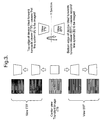
- FIG. 1 shows a cross-section through the known lenticular device which is being used to view images A-G.
- An array of cylindrical lenses 2 is arranged on a transparent substrate 4.
- Each image is segmented into a number of strips, for example 10 and under each lens 2 of the lenticular array, there is a set of image strips corresponding to a particular segmented region of images A-G. Under the first lens the strips will each correspond to the first segment of images A-G and under the next lens the strips will each correspond to the second segment of images A-G and so forth.
- Each lens 2 is arranged to focus in the plane of the strips such that only one strip can be viewed from one viewing position through each lens 2.
- each strip of image D will be seen from straight on whereas on tilting a few degrees off-axis the strips from images C or E will be seen.
- the strips are arranged as slices of an image, i.e. the strips A are all slices from one image, similarly for B, C etc.
- the images could be related or unrelated.
- the simplest device would have two images that would flip between each other as the device is tilted.
- the images could be a series of images that are shifted laterally strip to strip generating a lenticular animation effect so that the image appears to move.
- the change from image to image could give rise to more complex animations (parts of the image change in a quasi-continuous fashion), morphing (one image transforms in small steps to another image) or zooming (an image gets larger or smaller in steps).
- Figure 2 shows the lenticular device in perspective view although for simplicity only two image strips per lens are shown labelled A,B respectively.
- the appearance of the device shown in Figure 2 to the observer is illustrated in Figure 3 .
- TTF top tilted forward
- view BTF bottom tilted forward
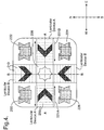
- Figure 4 illustrates a first example according to the invention in which there are two sets of cylindrical microlens arrays which are oriented at 90° to each other and located above respective image strips (in a similar way to Figures 1 and 2 ).
- lenticular device A has microlenses 200 extending in the north-south direction so that, on east-west tilting, about axis B-B it combines with its image strips to produce an image of a moving chevron along line A-A, each device creating a chevron moving in mutually opposite directions shown by arrows 221A,221B.
- Lenticular device B has microlenses 210 extending in the east-west direction so that, on north-south tilting about axis A-A it combines with its image strips to create an image of a moving chevron along line B-B, each device creating a chevron moving in mutually opposite directions.
- lenticular devices A spaced apart along the axis A-A and 2 lenticular devices B spaced apart along the axis B-B. Pairs of lenticular devices A,B abut at respective corners.
- five holographic generating structures 220, 222, 224, 226, 228 are located in the spaces defined between the lenticular devices A,B.
- the respective lenticular animations occur only when the security device is tilted around an axis which is perpendicular to the direction in which the cylindrical lens-lets 200,210 exhibit their periodic variations in curvature.
- the lenticular animation of the chevrons horizontally across the device will occur along the line A-A when the device is tilted around the line B-B.
- the lenticular animation of the chevrons vertically across the device will occur along the line B-B when the device is tilted around the line A-A.
- the animation itself can take place in any direction and is purely dependent on the artwork.
- the holographic generating structures 220-228 in Figure 4 can be in the form of holograms or DOVID image elements.
- the holographic and lenticular devices are in separate areas, however, it should be understood that this example is purely illustrative and for example the holographic generating structures 220-228 could be located in a central band or strip and the lenticular devices A,B could be located in one or more regions on either side.
- the image provided by the lenticular device and the image provided by the holographic generating structures could be integrated into a single image by each providing components of a single image.
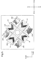
- the cylindrical microlens array and the microimage strips are arranged such that for at least one of the lenticular devices the direction the cylindrical lens-lets exhibit their periodic variations in curvature lies at 45 degrees to the x (line A-A in Figure 4 ) or y- axis (line B-B in Figure 4 ) or any angle in between which may be deemed advantageous.
- the 45 degree angle is particularly advantageous - since documents tend to be tilted only north-south or east-west, the device can appear to move with all tilts.
- Such a device is illustrated in Figure 5 where although the two sets of cylindrical microlens arrays 200,210 are oriented at 90° to each other they are also both orientated at 45° to the x and y axes of the security device. On tilting the device around either the x or y axis both lenticular devices will exhibit an animation, in this case the chevrons from each of the devices will appear to move towards the centre of the device.
- Figure 6 illustrates an example lenticular device suitable for use in the current invention comprising four image strips A-D which are different views of the same image in order to create a lenticular animation effect.
- the image areas of the strips are creating by creating a series of raised regions or bumps in a resin layer 26 provided on a transparent PET spacer layer 24.
- a cylindrical lens array 20 is cast cured or embossed into a resin layer 21 on the layer 24.
- a coloured ink is then transferred onto the raised regions typically using a lithographic, flexographic or gravure process.
- image strips A and B are printed with one colour 27 and image strips C and D are printed with a second colour 28.
- different image elements within one strip or in different strips can be formed by different gratings.
- the difference may be in the pitch of the grating or rotation.
- This can be used to achieve a multicoloured diffractive image which will also exhibit a lenticular optical effect such as an animation.
- a lenticular optical effect such as an animation.
- the image strips creating the chevrons for lenticular device A in the example illustrated in Figure 4 had been created by writing different diffraction tracks for each strip then as the device in Figure 4 is tilted around the line B-B lenticular animation of the chevrons will occur during which the colour of the chevrons will progressively change due to the different diffraction gratings.
- a preferred method for writing such a grating would be to use electron beam writing techniques or dot matrix techniques.
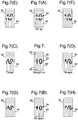
- Figures 7 and 7A-7H illustrate another example according to the invention.
- two lenticular devices 30,40 are provided abutting one another each having a form similar to that shown in Figures 1 to 3 .
- the lenticular device 30 has cylindrical lenses 32 extending horizontally in Figure 7 while the lenticular device 40 has cylindrical lenses extending vertically and thus orthogonal to the lenses 32.
- the image strips under the lenses 32 define an upper half portion 34 of the numeral "10" in such a way that as the lenticular device 30 is tilted about an axis parallel to the lenses 32, the half portion 34 of the symbol "10" will appear to move away or up or towards or down the point of abutment between the lenticular devices. These movements are shown in Figures 7A and 7B respectively.
- image strips are defined representing the lower half portion of the symbol "10" as shown at 44 so that when the device is tilted about the axes of the lenses 42, the lower portion 44 will move to the left or right respectively ( Figures 7C and 7D ).
- the image strips are registered to the lenses but this is not essential.
- Figure 7 also illustrates the effect of tilting both up and to the left or right or down and to the left or right in Figures 7E-7H respectively.
- the image strips are printed as is known while the cylindrical lenses are embossed or cast-cured into a suitable resin layer.
- the image strips can also be formed as a relief structure and a variety of different relief structures suitable for this are shown in Figure 8 .
- Figure 8A illustrates image regions of the strips (IM) in the form of embossed or recessed lines while the non-embossed lines correspond to the non-imaged regions of the strips (NI).
- Figure 8B illustrates image regions of the strips in the form of debossed lines or bumps.
- the relief structures can be in the form of diffraction gratings ( Figure 8C ) or moth-eye/fine pitch gratings ( Figure 8D ).
- inventions 8A and 8B can be further provided with gratings as shown in Figures 8E and 8F respectively.
- Figure 8G illustrates the use of a simple scattering structure providing an achromatic effect.
- the recesses of Figure 8A could be provided with an ink or the debossed regions or bumps could be provided with an ink.
- the latter is shown in Figure 8H where ink layers 100 are provided on bumps 110.
- Figure 8I illustrates the use of an Aztec structure.
- image and non-image areas could be defined by combinations of different elements types, e.g. the image areas could be formed from moth-eye structures whilst the non-image areas could be formed from a grating. Or even the image and non-image areas could be formed by gratings of different pitch or orientation.
- the height or depth of the bumps/recesses is preferably in the range 0.5-10 ⁇ m and more preferably in the range 1-5 ⁇ m.
- Typical widths of the bumps/recesses will be defined by the nature of the artwork but would typically be less than 100 ⁇ m, more preferably less than 50 ⁇ m and even more preferably less than 25 microns.
- the width of the image strip and therefore the width of the bumps or recesses will be dependent on the type of optical effect required for example if the diameter of the focussing elements is 30 ⁇ m then a simple switch effects between two views A and B could be achieved using 15 ⁇ m wide image strips.
- lenticular focussing elements are described with reference to cylindrical lenses, other suitable elements include micro-mirrors.
- the security device of the current invention can be made machine readable by the introduction of detectable materials in any of the layers or by the introduction of separate machine-readable layers.
- Detectable materials that react to an external stimulus include but are not limited to fluorescent, phosphorescent, infrared absorbing, thermochromic, photochromic, magnetic, electrochromic, conductive and piezochromic materials.
- the security device of the current invention may also comprise additional security features such as any desired printed images, metallic layers which may be opaque, semitransparent or screened. Such metallic layers may contain negative or positive indicia created by known demetallisation processes.
- Additional optically variable materials can be included in the security device such as thin film interference elements, liquid crystal material and photonic crystal materials. Such materials may be in the form of filmic layers or as pigmented materials suitable for application by printing.
- a metallic layer can be used to conceal the presence of a machine readable dark magnetic layer.
- a magnetic material When a magnetic material is incorporated into the device the magnetic material can be applied in any design but common examples include the use of magnetic tramlines or the use of magnetic blocks to form a coded structure.
- Suitable magnetic materials include iron oxide pigments (Fe 2 O 3 or Fe 3 O 4 ), barium or strontium ferrites, iron, nickel, cobalt and alloys of these.
- alloys includes materials such as Nickel:Cobalt, Iron:Aluminium:Nickel:Cobalt and the like.
- Flake Nickel materials can be used; in addition Iron flake materials are suitable. Typical nickel flakes have lateral dimensions in the range 5-50 microns and a thickness less than 2 microns. Typical iron flakes have lateral dimensions in the range 10-30 microns and a thickness less than 2 microns.
- a transparent magnetic layer can be incorporated at any position within the device structure.
- Suitable transparent magnetic layers containing a distribution of particles of a magnetic material of a size and distributed in a concentration at which the magnetic layer remains transparent are described in WO03091953 and WO03091952 .
- the security device of the current invention may be incorporated in a security document such that the device is incorporated in a transparent region of the document.
- the security document may have a substrate formed from any conventional material including paper and polymer. Techniques are known in the art for forming transparent regions in each of these types of substrate.
- WO8300659 describes a polymer banknote formed from a transparent substrate comprising an opacifying coating on both sides of the substrate. The opacifying coating is omitted in localised regions on both sides of the substrate to form a transparent region.
- EP1141480 describes a method of making a transparent region in a paper substrate. Other methods for forming transparent regions in paper substrates are described in EP0723501 , EP0724519 , EP1398174 and WO03054297 .
Claims (14)
- Dispositif de sécurité comprenant au moins deux dispositifs lenticulaires (30, 40), chaque dispositif lenticulaire ayant une série d'éléments de focalisation lenticulaires allongés (32) tels que des lentilles ou des micromiroirs cylindriques, situés au-dessus d'ensembles respectifs de bandes d'images (A, B), les directions allongées étant orthogonales, caractérisé en ce que les deux dispositifs lenticulaires (30, 40), quand on les observe dans au moins une condition d'observation, par exemple perpendiculairement, présentent une image reconnaissable à l'oeil nu de l'observateur constituée par des parties d'image (33, 44) venant de chaque dispositif lenticulaire, ces bandes d'image définissant des vues différentes de la partie graphique d'image respective, ce qui fait que, lorsque le dispositif de sécurité est incliné autour d'un axe parallèle à la direction allongée de l'un ou l'autre des dispositifs lenticulaires, la partie d'image respective semble bouger latéralement tandis que l'autre partie d'image reste fixe.
- Dispositif de sécurité selon la revendication 1, dans lequel les deux dispositifs lenticulaires sont disposés de façon adjacente l'un à l'autre et de préférence sont contigus l'un à l'autre.
- Dispositif de sécurité selon la revendication 1 ou la revendication 2, dans lequel l'image reconnaissable consiste en soit un symbole, soit un élément graphique, soit un caractère.
- Dispositif de sécurité selon l'une quelconque des revendications précédentes, dans lequel les bandes d'image (A, B) sont mises en correspondance avec les éléments de focalisation lenticulaires (32).
- Dispositif de sécurité selon l'une quelconque des revendications précédentes, dans lequel les bandes d'image (A, B) sont définies par des encres.
- Dispositif de sécurité selon l'une quelconque des revendications 1 à 4, dans lequel les bandes d'image (A, B) sont définies par une structure en relief, généralement gaufrée ou coulée-polymérisée dans un substrat, cette structure en relief comportant de préférence des structures à réseau de diffraction.
- Dispositif de sécurité selon l'une quelconque des revendications précédentes, dans lequel la largeur de chaque bande d'image (A, B) est moins que 50 microns, de préférence moins que 20 microns, idéalement située dans la plage de 5 à 10 microns.
- Dispositif de sécurité selon l'une quelconque des revendications précédentes, dans lequel la série d'éléments de focalisation lenticulaires a une périodicité située dans la plage de 5 à 200 microns, de préférence de 10 à 60 microns, idéalement de 20 à 40 microns.
- Dispositif de sécurité selon l'une quelconque des revendications précédentes, dans lequel les éléments de focalisation lenticulaires (32) ont été formés par un processus de gaufrage thermique ou de réplication par coulée-polymérisation.
- Article pourvu d'un dispositif de sécurité selon l'une quelconque des revendications précédentes, cet article étant sélectionné de préférence parmi les billets de banque, les chèques, les passeports, les cartes d'identité, les certificats d'authenticité, les timbres fiscaux et d'autres documents pour authentifier la valeur ou l'identité personnelle.
- Article selon la revendication 10, cet article comprenant un substrat avec une partie transparente, sur les côtés opposés duquel les éléments de focalisation lenticulaires et les bandes d'image sont prévus respectivement.
- Procédé de fabrication d'un dispositif de sécurité, ce procédé comprenant la prévision d'au moins deux dispositifs lenticulaires (30, 40), chaque dispositif lenticulaire ayant une série d'éléments de focalisation lenticulaires allongés (32) situés au-dessus d'ensembles respectifs de bandes d'images (A, B), lesdites directions allongées étant orthogonales, caractérisé en ce que les deux dispositifs lenticulaires (30, 40), quand on les observe dans au moins une condition d'observation, par exemple perpendiculairement, présentent une image reconnaissable à l'oeil nu de l'observateur constituée par des parties d'image (34, 44) venant de chaque dispositif lenticulaire, les bandes d'image définissant des vues différentes de la partie d'image respective, ce qui fait que, lorsque le dispositif de sécurité est incliné autour d'un axe parallèle à la direction allongée de l'un ou l'autre des dispositifs lenticulaires, la partie d'image respective semble bouger latéralement tandis que l'autre partie d'image reste fixe.
- Procédé selon la revendication 12, dans lequel les deux dispositifs lenticulaires (30, 40) sont disposés de façon adjacente l'un à l'autre et de préférence sont contigus l'un à l'autre.
- Procédé selon la revendication 12 ou la revendication 13, pour fabriquer un dispositif de sécurité selon l'une quelconque des revendications 1 à 9.
Applications Claiming Priority (3)
| Application Number | Priority Date | Filing Date | Title |
|---|---|---|---|
| US27277109P | 2009-10-30 | 2009-10-30 | |
| GBGB0919109.9A GB0919109D0 (en) | 2009-10-30 | 2009-10-30 | Security device |
| PCT/GB2010/001994 WO2011051669A1 (fr) | 2009-10-30 | 2010-10-27 | Dispositif de sécurité et son procédé de fabrication |
Publications (2)
| Publication Number | Publication Date |
|---|---|
| EP2493699A1 EP2493699A1 (fr) | 2012-09-05 |
| EP2493699B1 true EP2493699B1 (fr) | 2019-06-19 |
Family
ID=41434969
Family Applications (1)
| Application Number | Title | Priority Date | Filing Date |
|---|---|---|---|
| EP10775855.9A Not-in-force EP2493699B1 (fr) | 2009-10-30 | 2010-10-27 | Dispositif de sécurité et et son procédé de fabrication |
Country Status (9)
| Country | Link |
|---|---|
| US (1) | US20120268819A1 (fr) |
| EP (1) | EP2493699B1 (fr) |
| JP (1) | JP5922580B2 (fr) |
| CN (1) | CN102712204A (fr) |
| AU (1) | AU2010311163B2 (fr) |
| GB (1) | GB0919109D0 (fr) |
| IN (1) | IN2012DN02747A (fr) |
| MX (1) | MX2012004483A (fr) |
| WO (1) | WO2011051669A1 (fr) |
Families Citing this family (41)
| Publication number | Priority date | Publication date | Assignee | Title |
|---|---|---|---|---|
| GB201107657D0 (en) * | 2011-05-09 | 2011-06-22 | Rue De Int Ltd | Security device |
| RU2641316C9 (ru) | 2011-08-19 | 2019-03-21 | Визуал Физикс, Ллс | Опционально переводная оптическая система с уменьшенной толщиной |
| DE102011115125B4 (de) | 2011-10-07 | 2021-10-07 | Giesecke+Devrient Currency Technology Gmbh | Herstellung einer mikrooptischen Darstellungsanordnung |
| CA2881826C (fr) | 2012-08-17 | 2021-03-30 | Visual Physics, Llc | Processus de transfert de microstructures sur un substrat final |
| US10173453B2 (en) | 2013-03-15 | 2019-01-08 | Visual Physics, Llc | Optical security device |
| US9873281B2 (en) | 2013-06-13 | 2018-01-23 | Visual Physics, Llc | Single layer image projection film |
| GB201313363D0 (en) * | 2013-07-26 | 2013-09-11 | Rue De Int Ltd | Security devices and method of manufacture |
| GB201313362D0 (en) | 2013-07-26 | 2013-09-11 | Rue De Int Ltd | Security Devices and Methods of Manufacture |
| US10766292B2 (en) | 2014-03-27 | 2020-09-08 | Crane & Co., Inc. | Optical device that provides flicker-like optical effects |
| BR112016021736A2 (pt) | 2014-03-27 | 2017-08-15 | Visual Physics Llc | Dispositivo ótico que produz efeitos óticos de tipo cintilante |
| JP6658525B2 (ja) * | 2014-07-15 | 2020-03-04 | 凸版印刷株式会社 | 樹脂製シート、および、冊子 |
| MX2017000681A (es) | 2014-07-17 | 2018-03-12 | Visual Physics Llc | Un material de lamina polimerica mejorada para su uso en la fabricacion de documentos de seguridad polimericos tales como billetes de banco. |
| KR102497982B1 (ko) * | 2014-09-16 | 2023-02-09 | 크레인 시큐리티 테크놀로지스, 인크. | 보안 렌즈 층 |
| RU2712604C2 (ru) | 2015-02-11 | 2020-01-29 | КРАНЕ и КО., ИНК. | Способ наложения защитного устройства на поверхность подложки |
| GB2536877B (en) | 2015-03-23 | 2017-06-28 | De La Rue Int Ltd | Security device and method of manufacture |
| DE102015005911A1 (de) * | 2015-05-07 | 2016-11-10 | Giesecke & Devrient Gmbh | Optisch variables Sicherheitselement |
| GB2549215B (en) | 2015-06-10 | 2018-07-25 | De La Rue Int Ltd | Security devices and methods of manufacture thereof |
| MA42899A (fr) | 2015-07-10 | 2018-05-16 | De La Rue Int Ltd | Procédés de fabrication de documents de sécurité et de dispositifs de sécurité |
| JP6564279B2 (ja) * | 2015-08-27 | 2019-08-21 | 株式会社トプコン | 標尺及び水準測量方法 |
| JP2017058585A (ja) * | 2015-09-18 | 2017-03-23 | 株式会社エンプラス | 画像表示体、その製造方法および光学部品 |
| GB201520085D0 (en) * | 2015-11-13 | 2015-12-30 | Rue De Int Ltd | Methods of manufacturing image element arrays for security devices |
| KR102514973B1 (ko) * | 2015-12-18 | 2023-03-27 | 비쥬얼 피직스 엘엘씨 | 단일층 이미지 투영 필름 |
| GB2549724B (en) | 2016-04-26 | 2019-12-11 | De La Rue Int Ltd | Security devices and methods of manufacturing image patterns for security devices |
| US10656328B2 (en) * | 2016-04-29 | 2020-05-19 | Nuburu, Inc. | Monolithic visible wavelength fiber laser |
| GB2550168B (en) | 2016-05-11 | 2018-07-25 | De La Rue Int Ltd | Security device and method of manufacture |
| GB2557167B (en) | 2016-09-30 | 2020-03-04 | De La Rue Int Ltd | Security devices |
| KR102489526B1 (ko) | 2017-02-10 | 2023-01-17 | 크레인 앤 코, 인크 | 머신 판독가능 광학적 보안 디바이스 |
| GB2564122B (en) * | 2017-07-04 | 2021-01-13 | De La Rue Int Ltd | Optical devices and methods for their manufacture |
| MX2020007781A (es) * | 2018-01-23 | 2020-11-18 | Multi Color Corp | Etiqueta que incluye una disposición de lentes. |
| NL2020650B1 (en) * | 2018-03-23 | 2019-10-02 | Idemia The Netherlands B V | Security document with array of parallel semi-cylindrical lenses |
| FR3087015B1 (fr) * | 2018-10-08 | 2022-11-11 | Plastic Omnium Cie | Piece de carrosserie comprenant une paroi lenticulaire pour former une image holographique |
| GB2578117B (en) | 2018-10-16 | 2021-06-09 | De La Rue Int Ltd | Security devices and methods for their manufacture |
| GB2578773B (en) | 2018-11-08 | 2022-03-30 | De La Rue Int Ltd | Methods of manufacturing security device components |
| GB2580069B (en) | 2018-12-20 | 2022-06-15 | De La Rue Int Ltd | Security documents and methods of manufacture thereof |
| GB2584597B (en) | 2019-03-28 | 2023-01-18 | De La Rue Int Ltd | Security device and method of manufacture thereof |
| GB2588625B (en) | 2019-10-29 | 2022-12-14 | De La Rue Int Ltd | Method of forming a security device |
| JP2020173448A (ja) * | 2020-06-04 | 2020-10-22 | 株式会社エンプラス | 画像表示体、その製造方法および光学部品 |
| CA3192144A1 (fr) | 2020-09-11 | 2022-03-17 | John Godfrey | Dispositifs de securite et leurs procedes de fabrication |
| GB202101267D0 (en) | 2021-01-29 | 2021-03-17 | De La Rue Int Ltd | Security devices and methods of manufacture thereof |
| WO2023170132A1 (fr) | 2022-03-10 | 2023-09-14 | Basf Se | Laque de coulée pour sérigraphie |
| GB2621154A (en) | 2022-08-03 | 2024-02-07 | De La Rue Int Ltd | Security devices and methods of manufacture thereof |
Family Cites Families (24)
| Publication number | Priority date | Publication date | Assignee | Title |
|---|---|---|---|---|
| US4033059A (en) * | 1972-07-06 | 1977-07-05 | American Bank Note Company | Documents of value including intaglio printed transitory images |
| GB2125337B (en) | 1981-08-24 | 1985-05-01 | Commw Scient Ind Res Org | Improved banknotes and the like |
| DE3609090A1 (de) * | 1986-03-18 | 1987-09-24 | Gao Ges Automation Org | Wertpapier mit darin eingelagertem sicherheitsfaden und verfahren zur herstellung derselben |
| US4869946A (en) * | 1987-12-29 | 1989-09-26 | Nimslo Corporation | Tamperproof security card |
| GB9309673D0 (en) | 1993-05-11 | 1993-06-23 | De La Rue Holographics Ltd | Security device |
| AT401365B (de) | 1993-10-11 | 1996-08-26 | Oesterr Nationalbank | Wertpapier |
| DE4334847A1 (de) | 1993-10-13 | 1995-04-20 | Kurz Leonhard Fa | Wertdokument mit Fenster |
| GB9828770D0 (en) | 1998-12-29 | 1999-02-17 | Rue De Int Ltd | Security paper |
| BR0007172A (pt) * | 1999-09-30 | 2001-09-04 | Koninkl Philips Electronics Nv | Dispositivo lenticular, e, conjunto de dispositivos lenticulares |
| DE10163381A1 (de) | 2001-12-21 | 2003-07-03 | Giesecke & Devrient Gmbh | Sicherheitspapier sowie Verfahren und Vorrichtung zu seiner Herstellung |
| GB0209564D0 (en) | 2002-04-25 | 2002-06-05 | Rue De Int Ltd | Improvements in substrates |
| EP1398174A1 (fr) | 2002-09-10 | 2004-03-17 | Kba-Giori S.A. | Substrat renforcé pour papiers de valeur |
| JP4287131B2 (ja) * | 2002-12-09 | 2009-07-01 | 大日本印刷株式会社 | 真偽判定体 |
| ES2854709T3 (es) | 2003-11-21 | 2021-09-22 | Visual Physics Llc | Sistema de presentación de imágenes y de seguridad micro-óptico |
| US20070273679A1 (en) * | 2004-03-08 | 2007-11-29 | Barton Daniel J | Orientation data collection system |
| EP1747099B2 (fr) | 2004-04-30 | 2017-09-20 | De La Rue International Limited | Reseaux de microlentilles et de micro-images sur des substrats de securite transparents |
| WO2005115119A2 (fr) | 2004-05-25 | 2005-12-08 | Cowan, James, J. | Structure a relief de surface |
| JP2006227081A (ja) * | 2005-02-15 | 2006-08-31 | Sankoo:Kk | レンチキュラー効果印刷物及びその屈折部形成用の成形型 |
| NL1028776C2 (nl) * | 2005-04-14 | 2006-10-20 | Sdu Identification Bv | Identificatie en werkwijze voor het vervaardigen daarvan. |
| DE102005039113A1 (de) * | 2005-08-18 | 2007-02-22 | Zintzmeyer, Jörg | Mikro-Refraktionsbild |
| JP4978102B2 (ja) * | 2006-08-07 | 2012-07-18 | セイコーエプソン株式会社 | 印刷媒体 |
| GB2454752B (en) * | 2007-11-19 | 2012-05-23 | Rue De Int Ltd | Improvements in security devices |
| JP2009255320A (ja) * | 2008-04-14 | 2009-11-05 | Dainippon Printing Co Ltd | 身分証明書 |
| US8351087B2 (en) * | 2009-06-15 | 2013-01-08 | Ecole Polytechnique Federale De Lausanne (Epfl) | Authentication with built-in encryption by using moire parallax effects between fixed correlated s-random layers |
-
2009
- 2009-10-30 GB GBGB0919109.9A patent/GB0919109D0/en not_active Ceased
-
2010
- 2010-10-27 JP JP2012535918A patent/JP5922580B2/ja active Active
- 2010-10-27 EP EP10775855.9A patent/EP2493699B1/fr not_active Not-in-force
- 2010-10-27 US US13/499,386 patent/US20120268819A1/en not_active Abandoned
- 2010-10-27 IN IN2747DEN2012 patent/IN2012DN02747A/en unknown
- 2010-10-27 AU AU2010311163A patent/AU2010311163B2/en not_active Ceased
- 2010-10-27 WO PCT/GB2010/001994 patent/WO2011051669A1/fr active Application Filing
- 2010-10-27 CN CN2010800491766A patent/CN102712204A/zh active Pending
- 2010-10-27 MX MX2012004483A patent/MX2012004483A/es active IP Right Grant
Non-Patent Citations (1)
| Title |
|---|
| None * |
Also Published As
| Publication number | Publication date |
|---|---|
| MX2012004483A (es) | 2012-05-08 |
| US20120268819A1 (en) | 2012-10-25 |
| EP2493699A1 (fr) | 2012-09-05 |
| JP2013509313A (ja) | 2013-03-14 |
| AU2010311163B2 (en) | 2014-09-04 |
| GB0919109D0 (en) | 2009-12-16 |
| AU2010311163A1 (en) | 2012-05-03 |
| CN102712204A (zh) | 2012-10-03 |
| IN2012DN02747A (fr) | 2015-09-18 |
| JP5922580B2 (ja) | 2016-05-24 |
| WO2011051669A1 (fr) | 2011-05-05 |
Similar Documents
| Publication | Publication Date | Title |
|---|---|---|
| EP2493699B1 (fr) | Dispositif de sécurité et et son procédé de fabrication | |
| EP2493698B1 (fr) | Dispositifs de sécurité et procédures de fabrication associées | |
| EP3024662B1 (fr) | Dispositif de sécurité et procédé de fabrication | |
| EP2493700B1 (fr) | Procédé de fabrication d'un dispositif de sécurité | |
| EP2542423B2 (fr) | Dispositif d'agrandissement par effet de moire | |
| EP3174730B1 (fr) | Dispositif de sécurité et son procédé de fabrication | |
| EP3455083B1 (fr) | Dispositif de sécurité et procédé de fabrication | |
| US20130044362A1 (en) | Optical device | |
| AU2015201281A1 (en) | Security device and method of manufacturing the same |
Legal Events
| Date | Code | Title | Description |
|---|---|---|---|
| PUAI | Public reference made under article 153(3) epc to a published international application that has entered the european phase |
Free format text: ORIGINAL CODE: 0009012 |
|
| 17P | Request for examination filed |
Effective date: 20120330 |
|
| AK | Designated contracting states |
Kind code of ref document: A1 Designated state(s): AL AT BE BG CH CY CZ DE DK EE ES FI FR GB GR HR HU IE IS IT LI LT LU LV MC MK MT NL NO PL PT RO RS SE SI SK SM TR |
|
| DAX | Request for extension of the european patent (deleted) | ||
| STAA | Information on the status of an ep patent application or granted ep patent |
Free format text: STATUS: EXAMINATION IS IN PROGRESS |
|
| 17Q | First examination report despatched |
Effective date: 20180328 |
|
| GRAP | Despatch of communication of intention to grant a patent |
Free format text: ORIGINAL CODE: EPIDOSNIGR1 |
|
| STAA | Information on the status of an ep patent application or granted ep patent |
Free format text: STATUS: GRANT OF PATENT IS INTENDED |
|
| INTG | Intention to grant announced |
Effective date: 20190110 |
|
| GRAS | Grant fee paid |
Free format text: ORIGINAL CODE: EPIDOSNIGR3 |
|
| GRAA | (expected) grant |
Free format text: ORIGINAL CODE: 0009210 |
|
| STAA | Information on the status of an ep patent application or granted ep patent |
Free format text: STATUS: THE PATENT HAS BEEN GRANTED |
|
| AK | Designated contracting states |
Kind code of ref document: B1 Designated state(s): AL AT BE BG CH CY CZ DE DK EE ES FI FR GB GR HR HU IE IS IT LI LT LU LV MC MK MT NL NO PL PT RO RS SE SI SK SM TR |
|
| REG | Reference to a national code |
Ref country code: GB Ref legal event code: FG4D |
|
| REG | Reference to a national code |
Ref country code: CH Ref legal event code: EP |
|
| REG | Reference to a national code |
Ref country code: IE Ref legal event code: FG4D |
|
| REG | Reference to a national code |
Ref country code: DE Ref legal event code: R096 Ref document number: 602010059557 Country of ref document: DE |
|
| REG | Reference to a national code |
Ref country code: AT Ref legal event code: REF Ref document number: 1144975 Country of ref document: AT Kind code of ref document: T Effective date: 20190715 |
|
| REG | Reference to a national code |
Ref country code: NL Ref legal event code: FP |
|
| REG | Reference to a national code |
Ref country code: CH Ref legal event code: NV Representative=s name: VALIPAT S.A. C/O BOVARD SA NEUCHATEL, CH |
|
| PG25 | Lapsed in a contracting state [announced via postgrant information from national office to epo] |
Ref country code: NO Free format text: LAPSE BECAUSE OF FAILURE TO SUBMIT A TRANSLATION OF THE DESCRIPTION OR TO PAY THE FEE WITHIN THE PRESCRIBED TIME-LIMIT Effective date: 20190919 Ref country code: LT Free format text: LAPSE BECAUSE OF FAILURE TO SUBMIT A TRANSLATION OF THE DESCRIPTION OR TO PAY THE FEE WITHIN THE PRESCRIBED TIME-LIMIT Effective date: 20190619 Ref country code: AL Free format text: LAPSE BECAUSE OF FAILURE TO SUBMIT A TRANSLATION OF THE DESCRIPTION OR TO PAY THE FEE WITHIN THE PRESCRIBED TIME-LIMIT Effective date: 20190619 Ref country code: SE Free format text: LAPSE BECAUSE OF FAILURE TO SUBMIT A TRANSLATION OF THE DESCRIPTION OR TO PAY THE FEE WITHIN THE PRESCRIBED TIME-LIMIT Effective date: 20190619 Ref country code: HR Free format text: LAPSE BECAUSE OF FAILURE TO SUBMIT A TRANSLATION OF THE DESCRIPTION OR TO PAY THE FEE WITHIN THE PRESCRIBED TIME-LIMIT Effective date: 20190619 |
|
| PGFP | Annual fee paid to national office [announced via postgrant information from national office to epo] |
Ref country code: FR Payment date: 20190913 Year of fee payment: 10 |
|
| REG | Reference to a national code |
Ref country code: LT Ref legal event code: MG4D |
|
| PG25 | Lapsed in a contracting state [announced via postgrant information from national office to epo] |
Ref country code: LV Free format text: LAPSE BECAUSE OF FAILURE TO SUBMIT A TRANSLATION OF THE DESCRIPTION OR TO PAY THE FEE WITHIN THE PRESCRIBED TIME-LIMIT Effective date: 20190619 Ref country code: GR Free format text: LAPSE BECAUSE OF FAILURE TO SUBMIT A TRANSLATION OF THE DESCRIPTION OR TO PAY THE FEE WITHIN THE PRESCRIBED TIME-LIMIT Effective date: 20190920 Ref country code: BG Free format text: LAPSE BECAUSE OF FAILURE TO SUBMIT A TRANSLATION OF THE DESCRIPTION OR TO PAY THE FEE WITHIN THE PRESCRIBED TIME-LIMIT Effective date: 20190919 Ref country code: RS Free format text: LAPSE BECAUSE OF FAILURE TO SUBMIT A TRANSLATION OF THE DESCRIPTION OR TO PAY THE FEE WITHIN THE PRESCRIBED TIME-LIMIT Effective date: 20190619 |
|
| PG25 | Lapsed in a contracting state [announced via postgrant information from national office to epo] |
Ref country code: PT Free format text: LAPSE BECAUSE OF FAILURE TO SUBMIT A TRANSLATION OF THE DESCRIPTION OR TO PAY THE FEE WITHIN THE PRESCRIBED TIME-LIMIT Effective date: 20191021 Ref country code: EE Free format text: LAPSE BECAUSE OF FAILURE TO SUBMIT A TRANSLATION OF THE DESCRIPTION OR TO PAY THE FEE WITHIN THE PRESCRIBED TIME-LIMIT Effective date: 20190619 Ref country code: CZ Free format text: LAPSE BECAUSE OF FAILURE TO SUBMIT A TRANSLATION OF THE DESCRIPTION OR TO PAY THE FEE WITHIN THE PRESCRIBED TIME-LIMIT Effective date: 20190619 Ref country code: RO Free format text: LAPSE BECAUSE OF FAILURE TO SUBMIT A TRANSLATION OF THE DESCRIPTION OR TO PAY THE FEE WITHIN THE PRESCRIBED TIME-LIMIT Effective date: 20190619 Ref country code: SK Free format text: LAPSE BECAUSE OF FAILURE TO SUBMIT A TRANSLATION OF THE DESCRIPTION OR TO PAY THE FEE WITHIN THE PRESCRIBED TIME-LIMIT Effective date: 20190619 |
|
| PGFP | Annual fee paid to national office [announced via postgrant information from national office to epo] |
Ref country code: DE Payment date: 20191015 Year of fee payment: 10 Ref country code: FI Payment date: 20191009 Year of fee payment: 10 Ref country code: NL Payment date: 20191014 Year of fee payment: 10 |
|
| PG25 | Lapsed in a contracting state [announced via postgrant information from national office to epo] |
Ref country code: IT Free format text: LAPSE BECAUSE OF FAILURE TO SUBMIT A TRANSLATION OF THE DESCRIPTION OR TO PAY THE FEE WITHIN THE PRESCRIBED TIME-LIMIT Effective date: 20190619 Ref country code: IS Free format text: LAPSE BECAUSE OF FAILURE TO SUBMIT A TRANSLATION OF THE DESCRIPTION OR TO PAY THE FEE WITHIN THE PRESCRIBED TIME-LIMIT Effective date: 20191019 Ref country code: SM Free format text: LAPSE BECAUSE OF FAILURE TO SUBMIT A TRANSLATION OF THE DESCRIPTION OR TO PAY THE FEE WITHIN THE PRESCRIBED TIME-LIMIT Effective date: 20190619 Ref country code: ES Free format text: LAPSE BECAUSE OF FAILURE TO SUBMIT A TRANSLATION OF THE DESCRIPTION OR TO PAY THE FEE WITHIN THE PRESCRIBED TIME-LIMIT Effective date: 20190619 |
|
| PG25 | Lapsed in a contracting state [announced via postgrant information from national office to epo] |
Ref country code: TR Free format text: LAPSE BECAUSE OF FAILURE TO SUBMIT A TRANSLATION OF THE DESCRIPTION OR TO PAY THE FEE WITHIN THE PRESCRIBED TIME-LIMIT Effective date: 20190619 |
|
| PGFP | Annual fee paid to national office [announced via postgrant information from national office to epo] |
Ref country code: AT Payment date: 20190925 Year of fee payment: 10 Ref country code: CH Payment date: 20191015 Year of fee payment: 10 |
|
| PG25 | Lapsed in a contracting state [announced via postgrant information from national office to epo] |
Ref country code: PL Free format text: LAPSE BECAUSE OF FAILURE TO SUBMIT A TRANSLATION OF THE DESCRIPTION OR TO PAY THE FEE WITHIN THE PRESCRIBED TIME-LIMIT Effective date: 20190619 Ref country code: DK Free format text: LAPSE BECAUSE OF FAILURE TO SUBMIT A TRANSLATION OF THE DESCRIPTION OR TO PAY THE FEE WITHIN THE PRESCRIBED TIME-LIMIT Effective date: 20190619 |
|
| PGFP | Annual fee paid to national office [announced via postgrant information from national office to epo] |
Ref country code: GB Payment date: 20191024 Year of fee payment: 10 |
|
| PG25 | Lapsed in a contracting state [announced via postgrant information from national office to epo] |
Ref country code: IS Free format text: LAPSE BECAUSE OF FAILURE TO SUBMIT A TRANSLATION OF THE DESCRIPTION OR TO PAY THE FEE WITHIN THE PRESCRIBED TIME-LIMIT Effective date: 20200224 Ref country code: MC Free format text: LAPSE BECAUSE OF FAILURE TO SUBMIT A TRANSLATION OF THE DESCRIPTION OR TO PAY THE FEE WITHIN THE PRESCRIBED TIME-LIMIT Effective date: 20190619 |
|
| REG | Reference to a national code |
Ref country code: DE Ref legal event code: R097 Ref document number: 602010059557 Country of ref document: DE |
|
| PLBE | No opposition filed within time limit |
Free format text: ORIGINAL CODE: 0009261 |
|
| STAA | Information on the status of an ep patent application or granted ep patent |
Free format text: STATUS: NO OPPOSITION FILED WITHIN TIME LIMIT |
|
| PG2D | Information on lapse in contracting state deleted |
Ref country code: IS |
|
| PG25 | Lapsed in a contracting state [announced via postgrant information from national office to epo] |
Ref country code: LU Free format text: LAPSE BECAUSE OF NON-PAYMENT OF DUE FEES Effective date: 20191027 |
|
| 26N | No opposition filed |
Effective date: 20200603 |
|
| REG | Reference to a national code |
Ref country code: BE Ref legal event code: MM Effective date: 20191031 |
|
| PG25 | Lapsed in a contracting state [announced via postgrant information from national office to epo] |
Ref country code: SI Free format text: LAPSE BECAUSE OF FAILURE TO SUBMIT A TRANSLATION OF THE DESCRIPTION OR TO PAY THE FEE WITHIN THE PRESCRIBED TIME-LIMIT Effective date: 20190619 Ref country code: BE Free format text: LAPSE BECAUSE OF NON-PAYMENT OF DUE FEES Effective date: 20191031 |
|
| PG25 | Lapsed in a contracting state [announced via postgrant information from national office to epo] |
Ref country code: IE Free format text: LAPSE BECAUSE OF NON-PAYMENT OF DUE FEES Effective date: 20191027 |
|
| REG | Reference to a national code |
Ref country code: DE Ref legal event code: R119 Ref document number: 602010059557 Country of ref document: DE |
|
| PG25 | Lapsed in a contracting state [announced via postgrant information from national office to epo] |
Ref country code: CY Free format text: LAPSE BECAUSE OF FAILURE TO SUBMIT A TRANSLATION OF THE DESCRIPTION OR TO PAY THE FEE WITHIN THE PRESCRIBED TIME-LIMIT Effective date: 20190619 |
|
| REG | Reference to a national code |
Ref country code: CH Ref legal event code: PL Ref country code: FI Ref legal event code: MAE |
|
| REG | Reference to a national code |
Ref country code: NL Ref legal event code: MM Effective date: 20201101 |
|
| REG | Reference to a national code |
Ref country code: AT Ref legal event code: MM01 Ref document number: 1144975 Country of ref document: AT Kind code of ref document: T Effective date: 20201027 |
|
| GBPC | Gb: european patent ceased through non-payment of renewal fee |
Effective date: 20201027 |
|
| PG25 | Lapsed in a contracting state [announced via postgrant information from national office to epo] |
Ref country code: HU Free format text: LAPSE BECAUSE OF FAILURE TO SUBMIT A TRANSLATION OF THE DESCRIPTION OR TO PAY THE FEE WITHIN THE PRESCRIBED TIME-LIMIT; INVALID AB INITIO Effective date: 20101027 Ref country code: MT Free format text: LAPSE BECAUSE OF FAILURE TO SUBMIT A TRANSLATION OF THE DESCRIPTION OR TO PAY THE FEE WITHIN THE PRESCRIBED TIME-LIMIT Effective date: 20190619 Ref country code: NL Free format text: LAPSE BECAUSE OF NON-PAYMENT OF DUE FEES Effective date: 20201101 Ref country code: DE Free format text: LAPSE BECAUSE OF NON-PAYMENT OF DUE FEES Effective date: 20210501 Ref country code: FR Free format text: LAPSE BECAUSE OF NON-PAYMENT OF DUE FEES Effective date: 20201031 Ref country code: FI Free format text: LAPSE BECAUSE OF NON-PAYMENT OF DUE FEES Effective date: 20201027 |
|
| PG25 | Lapsed in a contracting state [announced via postgrant information from national office to epo] |
Ref country code: LI Free format text: LAPSE BECAUSE OF NON-PAYMENT OF DUE FEES Effective date: 20201031 Ref country code: GB Free format text: LAPSE BECAUSE OF NON-PAYMENT OF DUE FEES Effective date: 20201027 Ref country code: CH Free format text: LAPSE BECAUSE OF NON-PAYMENT OF DUE FEES Effective date: 20201031 Ref country code: AT Free format text: LAPSE BECAUSE OF NON-PAYMENT OF DUE FEES Effective date: 20201027 |
|
| REG | Reference to a national code |
Ref country code: AT Ref legal event code: UEP Ref document number: 1144975 Country of ref document: AT Kind code of ref document: T Effective date: 20190619 |
|
| PG25 | Lapsed in a contracting state [announced via postgrant information from national office to epo] |
Ref country code: MK Free format text: LAPSE BECAUSE OF FAILURE TO SUBMIT A TRANSLATION OF THE DESCRIPTION OR TO PAY THE FEE WITHIN THE PRESCRIBED TIME-LIMIT Effective date: 20190619 |