EP2493076A1 - Inductive proximity sensor - Google Patents
Inductive proximity sensor Download PDFInfo
- Publication number
- EP2493076A1 EP2493076A1 EP20120156521 EP12156521A EP2493076A1 EP 2493076 A1 EP2493076 A1 EP 2493076A1 EP 20120156521 EP20120156521 EP 20120156521 EP 12156521 A EP12156521 A EP 12156521A EP 2493076 A1 EP2493076 A1 EP 2493076A1
- Authority
- EP
- European Patent Office
- Prior art keywords
- differential signal
- receiver
- signal
- proximity sensor
- inductive proximity
- Prior art date
- Legal status (The legal status is an assumption and is not a legal conclusion. Google has not performed a legal analysis and makes no representation as to the accuracy of the status listed.)
- Granted
Links
Images


Classifications
-
- H—ELECTRICITY
- H03—ELECTRONIC CIRCUITRY
- H03K—PULSE TECHNIQUE
- H03K17/00—Electronic switching or gating, i.e. not by contact-making and –breaking
- H03K17/94—Electronic switching or gating, i.e. not by contact-making and –breaking characterised by the way in which the control signals are generated
- H03K17/945—Proximity switches
- H03K17/95—Proximity switches using a magnetic detector
- H03K17/952—Proximity switches using a magnetic detector using inductive coils
- H03K17/9525—Proximity switches using a magnetic detector using inductive coils controlled by an oscillatory signal
-
- H—ELECTRICITY
- H03—ELECTRONIC CIRCUITRY
- H03K—PULSE TECHNIQUE
- H03K17/00—Electronic switching or gating, i.e. not by contact-making and –breaking
- H03K17/94—Electronic switching or gating, i.e. not by contact-making and –breaking characterised by the way in which the control signals are generated
- H03K17/945—Proximity switches
- H03K17/95—Proximity switches using a magnetic detector
- H03K17/9502—Measures for increasing reliability
-
- H—ELECTRICITY
- H03—ELECTRONIC CIRCUITRY
- H03K—PULSE TECHNIQUE
- H03K17/00—Electronic switching or gating, i.e. not by contact-making and –breaking
- H03K17/94—Electronic switching or gating, i.e. not by contact-making and –breaking characterised by the way in which the control signals are generated
- H03K17/945—Proximity switches
- H03K17/95—Proximity switches using a magnetic detector
- H03K17/952—Proximity switches using a magnetic detector using inductive coils
- H03K2017/9527—Details of coils in the emitter or receiver; Magnetic detector comprising emitting and receiving coils
Definitions
- the invention relates generally to inductive proximity sensors. More particularly, the invention relates to inductive proximity sensor configurations having improved target detection.
- a proximity sensor may include an evaluator circuit having control circuitry for providing feedback indicative of the presence of a target of interest (e.g., typically a metal).
- inductive proximity sensors may often be used to detect the presence of different targets composed of various metals.
- targets e.g., steel and copper
- inductive proximity sensors are often used in applications where the sensor is required to operate in the presence of a strong external electromagnetic field, such as in the vicinity of resistive welding machines and other equipment. Such external electromagnetic fields may influence the performance of the sensors, such as by causing the ferrite core to saturate, thereby changing the sensitivity of the sensor and causing the output circuitry to malfunction.
- Typical proximity sensors are mounted in a surrounding system, which may be defined as a mechanical system in which the sensor is mounted. As the surrounding system is usually closer than a target of interest, the proximity sensor may sometimes return a fault trigger, where the surrounding system is sensed, rather than the target of interest.
- typical evaluation circuitry may generally use complex feed-forward or synchronous demodulation techniques. Such configurations further increase the complexity and cost of the typical proximity sensor.
- the present invention relates to an inductive proximity sensor having a multiple-receiver coil assembly and an evaluator circuit suitable for receiving a differential signal from the coil assembly.
- the multiple-receiver coil assembly includes at least one transmitter and two anti-connected receivers, In operation, due to inductance coupling between the transmitter and receivers, the two anti-connected receivers have an induced voltage, and the differential signal of the two induced voltages may be analyzed to determine the presence of a target.
- the inductive proximity sensor includes an evaluator circuit which receives the differential signal, determines a change in the differential signal, and determines whether a target is present based on a comparison between the change and a threshold.
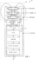
- FIG. 1 is a schematic diagram of an inductive proximity sensor, in accordance with an embodiment of the present techniques
- FIG. 2 is a schematic diagram of an arrangement of a multi-receiver coil structure in the inductive proximity sensor of FIG. 1 , in accordance with an embodiment of the present techniques;
- FIG. 3 is schematic diagram of another arrangement of a multi-receiver coil structure in the inductive proximity sensor of FIG. 1 , in accordance with an embodiment of the present techniques;
- FIG. 4 is a schematic diagram of another arrangement of a multi-receiver coil structure in the inductive proximity sensor of FIG. 1 , in accordance with an embodiment of the present techniques;
- FIG. 5 is a schematic diagram of an evaluator circuit in the inductive proximity sensor of FIG. 1 , in accordance with an embodiment of the present techniques
- FIG. 6 is a schematic diagram of an evaluator circuit having potentiometers in the inductive proximity sensor of FIG. 1 , in accordance with an embodiment of the present techniques;
- FIG. 7 is a schematic diagram of another embodiment of the evaluator circuit in the inductive proximity sensor of FIG. 1 , in accordance with an embodiment of the present techniques
- FIG. 8 is a schematic diagram of another embodiment of the evaluator circuit having potentiometers in the inductive proximity sensor of FIG. 1 , in accordance with an embodiment of the present techniques.
- Typical inductive proximity sensors include a coil assembly having a ferrous core.
- the coil assembly is driven by an oscillator to emit an electromagnetic field.
- a target i.e., an object to be sensed by the proximity sensor, usually composed of metal
- enters a sensing region of the electromagnetic field it increases the impedance of the coil, resulting in a change in oscillation amplitude of the electromagnetic field emitted by the coil.
- the change in oscillation amplitude is detected by an evaluator circuit which may compare the change to a threshold change and trigger an output circuit to indicate the presence of the target.
- Such inductive proximity sensors may have various performance drawbacks. Basing target detection on changes in the coil's impedance may lead to different ranges of detection for different types of targets, as various metals may have varying effects on the coil's impedance. For example, steel and copper may have different eddy-current induction capabilities, and typical inductive proximity sensors may have different sensing distances for each metal. The sensing distance ratio for steel and copper may be relatively large at approximately 1.0:0.3. Large sensing distance ratios between different types of targets may lead to poor performance in certain applications where the proximity sensor may be used to sense targets composed of different metals.
- using changes in coil impedance for target detection may also result in fault triggers (i.e., determining and indicating the presence of a target when no target is actually present).
- proximity sensors are typically mounted in a surrounding system.
- the surrounding system may also have an effect on the impedance of the coil, which may result in changes in the electromagnetic field of the coil assembly, such that the evaluator circuit inaccurately determines that a target is present.
- the proximity sensor may indicate that a target is present when it is not, or that a target is closer than it actually is.
- the ferrous core of typical inductive proximity sensors may also affect the performance of the proximity sensor after time, as the ferrous materials of the core may be easily saturated by strong electromagnetic fields. Therefore, in certain applications, such as those where proximity sensors are used in the vicinity of high electromagnetic fields, such as resistive welding machines, saturation of the ferrous core may result and cause deterioration in the performance of the proximity sensor.
- FIG. 1 is a schematic diagram of one embodiment of an inductive proximity sensor 10 having a multiple receiver coil assembly (multi-receiver coil assembly) 12 and an evaluator circuit 22.
- the multi-receiver coil assembly 12 has at least one transmitter 14 and two receivers 16, 18.
- the transmitter 14 and two receivers 16, 18 may each have a coil shape. These features may also be referred to as the transmitting coil 14 and the receiving coils 16, 18, respectively.
- the transmitter 14 is connected to an oscillator 20 or any other suitable alternating current provider which generates an alternating voltage to cause the transmitter 14 to emit an electromagnetic field.
- the electromagnetic field generated by the transmitter 14 induces a voltage in each of the receivers 16, 18 through inductance coupling.
- the two receivers 16, 18 are anti-connected; that is, the two receivers 16, 18 are connected in a differential coil arrangement.
- One terminal of each of the receiving coils 16, 18 are connected to a common ground, and the other terminal of each coil 16, 18 are connected to two resistors 21 (e.g., to form a bridge circuit) and to the evaluator circuit 22 which detects the voltage differential between the two receivers 16, 18 to determine if a target is detected. If the electromagnetic field emitted by the transmitter 14 is disturbed by an approaching target, the induced voltages in at least one of the two receivers 16, 18 will also change, as the target is typically closer to one of the receivers 16, 18 than the other.
- the inductance changes (also referred to as voltage changes) of the receivers 16, 18 result in a change in their differential signal 32.
- this differential signal 32 passes to the filter 24, an amplifier 26, an AC/DC converter 28, and output circuitry 30 in the evaluator circuit 22.
- the output circuitry 30 of the evaluator circuit 22 may provide an output signal 34 to indicate the presence of a target.
- Embodiments of the present techniques may reduce the sensing distance ratios between different target metals to be detected.
- Target detection is based on the change in the differential signal 32 of the two receivers 16, 18, and so detection is based on change in inductance coupling rather than on change in impedance.
- Inductance coupling changes are generally less dependent on the material of a target in comparison to impedance changes, so different types of target materials are less likely to generate a wide range of changes in inductance coupling in comparison to changes in impedance. Therefore, even in applications where the inductive proximity sensor 10 is used to sense the proximity of different types of targets, the detected change in inductance coupling of the two receivers 16, 18 generally will not vary significantly across targets having different metal compositions.
- the differential coil arrangement of the receivers 16, 18 is also suitable for cancelling out the effects from other objects (e.g., objects that are not the target to be detected).
- the evaluator circuit 22 processes the differential signal 32 to filter out or compensate for inductance changes caused by non-target objects. For instance, while typical inductive proximity sensors often generate fault triggers by mistaking a surrounding system for a detected target, the inductive proximity sensor 10 of the present techniques may be more accurate for detecting only a target of interest.
- the receiving coils 16, 18 are arranged in a certain way such that inductance changes caused by a surrounding system (e.g., mounting hardware of the proximity sensor 10) may be canceled out.
- a surrounding system e.g., mounting hardware of the proximity sensor 10
- the receiver coils 16, 18 may be configured (e.g., by different designs and/or sizes) to cancel out the effects of the surrounding system.
- the multi-receiver coil assembly 12 has a coil configuration without a ferrous core.
- the transmitting coil 14 and receiving coils 16, 18 may each be planar coils on a printed circuit board (PCB) or air-core wound coils.
- the multi-receiver coil assembly 12 uses some combination of planar coils on PCB or air-core wound coils for the transmitting coil 14 and receiving coils 16, 18.
- Such coil configurations typically do not include a ferrous core.
- the inductive proximity sensor 10 may be less susceptible to high electromagnetic fields, and may be less likely to degrade under such operating conditions.
- the transmitter 14 and receivers 16, 18 are arranged in various other configurations.
- the multi-receiver coil assembly 12a has two receivers 16, 18 arranged to be parallel and axially adjacent relative to one another.
- the transmitter 14 may be parallel with and axially adjacent to one of the receivers 18.
- a multi-receiver coil assembly 12b may include the transmitting coil 14 arranged planar to and concentrically within one receiving coil 18.
- the second receiver 16 may be parallel with and axially adjacent to the concentrically arranged receiving coil 14 and transmitting coil 18.
- some embodiments may include a multi-receiver coil assembly 12c having transmitting and receiving coils 14, 16, 18 all concentrically arranged in the same plane.
- the transmitting coil 14 may be concentrically between and planar to the two receiving coils 16, 18.
- an inductive proximity sensor 10 includes a multi-receiver coil assembly 12 having other configurations.
- the multi-receiver coil assembly 12 has multiple transmitters 14, and in some embodiments, the multi-receiver coil assembly 12 has more than two receivers.
- the multi-receiver coil assembly 12 has two transmitters 14 and no receivers. In such configurations, the transmitters 14 may inductively couple, and a differential signal between the two transmitters may be sampled for target detection.
- embodiments of the present techniques also include an evaluator circuit 22 suitable for efficiently processing the differential signal 32 from the anti-connected receivers 16, 18 to detect an approaching target.
- typical inductive proximity sensors generally include complex evaluator circuitry, such as positive feedback circuitry and synchronous demodulation circuitry
- some embodiments of the present techniques include an evaluator circuit 22 suitable for detecting and processing a differential signal 32 from the multi-receiver coil assembly 12 and analyzing a change in the differential signal 32 to determine the presence of a target.
- the evaluator circuit 22 need not include a demodulator or complex circuitry needed for positive feedback. Rather, the evaluator circuit 22 may simply filter and/or amplify a differential signal 32 from a multi-receiver coil assembly 12 to detect a target.
- the evaluator circuit 22a receives the differential signal 32 from the multi-receiver coil assembly 12 and processes the differential signal 32 to determine changes in the differential signal 32 which indicate the presence of a target.
- the resistors 21 are configured such that the differential signal 32 can be measured between the resistors 21.
- the resistors 21 have a resistance (which may either be different or the same) based on the manufacturing tolerance of the coils in the multi-receiver coil assembly 12.
- the resistors 21 are potentiometers 21 having resistances which are adjustable by the output circuitry 30.
- the differential signal 32 is transmitted to a filter 24 to increase the signal-to-noise ratio (SNR) of the differential signal 32.
- the filtered differential signal 32 is then amplified by the amplifier 26, such that changes in the differential signal 32 may be easier to detect.
- the amplified signal is then converted from AC to DC by the converter 28.
- the output circuitry 30 receives the filtered and amplified DC signal to determine whether a target is present.
- the output circuitry 30 compares the change in the sampled differential signal (e.g., in the form of a DC voltage) to a threshold (e.g., threshold voltage). Changes in the differential signal 32 above a certain threshold may indicate the presence of a target.
- the output circuitry 30 includes a microcontroller unit (MCU) 31 which outputs a signal 34 to indicate when a target is detected.
- the output circuitry 30 may include circuitry for further filtering the sampled differential signal, thereby further improving the SNR.
- the evaluator circuit may include potentiometers having resistances adjustable by the MCU of the output circuitry.
- the evaluator circuit 22b includes potentiometers 23 (e.g., in place of the resistors 21 of FIG. 5 ).
- the MCU 31 is configured to adjust the potentiometer 21 based on the sampled differential signal. For example, the MCU 31 may adjust the resistances of the potentiometer 21 to make the differential signal 32 easier to filter, amplify, and/or process.
- the converter 28 may not be necessary.
- the AC signal is converted to a DC voltage by an AC/DC converter 28 and transmitted to the output circuitry 30, and the output circuitry 30 compares the DC voltage with a threshold voltage to determine the presence of a target.
- the AC voltage is directly sampled by the output circuitry 30.
- the MCU 31 in the output circuitry 30 samples the differential signal 32.
- the evaluator circuit 22 may or may not include the converter 30, depending on the configuration of the evaluator circuit 22.
- FIG. 7 is a schematic diagram representing another embodiment of an evaluator circuit 22c.
- the evaluator circuit 22c receives the differential signal 32 from the multi-receiver coil assembly 12.
- the differential signal 32 is transmitted to a mixer 36 which mixes the differential signal 32 with a second signal 37.
- This second signal 37 may be any alternating current generated by a signal generator (e.g., an oscillator), and may typically have a frequency f2 that is different from the frequency f1 of the differential signal 32.
- the frequency f1 of the differential signal 32 may be substantially similar to the oscillation of the receiver coils 16, 18.
- the mixer 36 outputs the mixed signal, represented as having mixed frequencies of f1 + f2 and f1 - f2, to a low pass filter 38, which filters out high frequencies and outputs the remaining low frequencies (represented as f1-f2) of the mixed signal, as lower frequencies are typically more readily converted (e.g., relative to higher frequencies) for sampling.
- the low pass filtered signal is then transmitted to a filter 24 and an amplifier 26 which respectively increase the SNR and amplify the signal before it is transmitted to the output circuitry 30.
- the output circuitry 30 samples the differential signal to determine changes in the differential signal and compares the differential signal changes to a threshold.
- the output circuitry 30 outputs a signal 34 to indicate when a target is detected when the differential signal change is greater than the threshold.
- the evaluator circuit includes potentiometers, and the differential signal is measured from between two or more potentiometers.
- the evaluator circuit 22d illustrated in FIG. 8 includes two potentiometers 23 which are controlled by the MCU 31 of the output circuitry 30.
- the evaluator circuits 22c and 22d may also include an AC/DC converter suitable for converting the differential signal into a discretized (i.e., sampled, digital) differential signal.
- the output circuitry 30 of the evaluator circuit 22 may be different depending on the arrangement of the multi-receiver coil assembly 12. For instance, depending on the expected inductance changes in the receivers 16, 18, the output circuitry may compare the differential signal changes to different thresholds. Furthermore, depending on expected inductance changes from non-target objects (e.g., the surrounding system), the filter 24 may be adjusted to filter out non-target induced changes, In some embodiments, based on known or common targets, other aspects of the evaluator circuit 22 may be adjusted to improve target detection.
Abstract
Description
- The invention relates generally to inductive proximity sensors. More particularly, the invention relates to inductive proximity sensor configurations having improved target detection.
- Conventional inductive proximity sensors are generally known for sensing the presence of targets of interest in a sensing region. Such devices typically include an LC tuned oscillator for producing an oscillating electromagnetic field around a sensing coil. The sensing coil may typically have a ferrous core, which may have a T-shaped or E-shaped cross section. The sensing coil may shape and extend the electromagnetic field surrounding the coil in a sensing direction and/or concentrate or channel the electromagnetic field in other directions, such as behind and to the sides of the coil. A target which enters the sensing region of the proximity sensor may disrupt the electromagnetic field around the sensing coil and change the impedance of the coil sufficiently to alter the oscillating state of the electromagnetic field. A proximity sensor may include an evaluator circuit having control circuitry for providing feedback indicative of the presence of a target of interest (e.g., typically a metal).
- While advances have been made in the design of proximity sensors, such as to improve their sensing range and sensitivity, conventional proximity sensors may not perform consistently in certain applications. For example, inductive proximity sensors may often be used to detect the presence of different targets composed of various metals. However, different targets (e.g., steel and copper) typically have different effects on the impedance of the sensing coil, resulting in different sensing distance ratios for different metals. Furthermore, inductive proximity sensors are often used in applications where the sensor is required to operate in the presence of a strong external electromagnetic field, such as in the vicinity of resistive welding machines and other equipment. Such external electromagnetic fields may influence the performance of the sensors, such as by causing the ferrite core to saturate, thereby changing the sensitivity of the sensor and causing the output circuitry to malfunction. Typical proximity sensors are mounted in a surrounding system, which may be defined as a mechanical system in which the sensor is mounted. As the surrounding system is usually closer than a target of interest, the proximity sensor may sometimes return a fault trigger, where the surrounding system is sensed, rather than the target of interest. Moreover, typical evaluation circuitry may generally use complex feed-forward or synchronous demodulation techniques. Such configurations further increase the complexity and cost of the typical proximity sensor.
- The present invention relates to an inductive proximity sensor having a multiple-receiver coil assembly and an evaluator circuit suitable for receiving a differential signal from the coil assembly. In one embodiment, the multiple-receiver coil assembly includes at least one transmitter and two anti-connected receivers, In operation, due to inductance coupling between the transmitter and receivers, the two anti-connected receivers have an induced voltage, and the differential signal of the two induced voltages may be analyzed to determine the presence of a target. In some embodiments, the inductive proximity sensor includes an evaluator circuit which receives the differential signal, determines a change in the differential signal, and determines whether a target is present based on a comparison between the change and a threshold.
- These and other features, aspects, and advantages of the present invention will become better understood when the following detailed description is read with reference to the accompanying drawings in which like characters represent like parts throughout the drawings, wherein:
-
FIG. 1 is a schematic diagram of an inductive proximity sensor, in accordance with an embodiment of the present techniques; -
FIG. 2 is a schematic diagram of an arrangement of a multi-receiver coil structure in the inductive proximity sensor ofFIG. 1 , in accordance with an embodiment of the present techniques; -
FIG. 3 is schematic diagram of another arrangement of a multi-receiver coil structure in the inductive proximity sensor ofFIG. 1 , in accordance with an embodiment of the present techniques; -
FIG. 4 is a schematic diagram of another arrangement of a multi-receiver coil structure in the inductive proximity sensor ofFIG. 1 , in accordance with an embodiment of the present techniques; -
FIG. 5 is a schematic diagram of an evaluator circuit in the inductive proximity sensor ofFIG. 1 , in accordance with an embodiment of the present techniques; -
FIG. 6 is a schematic diagram of an evaluator circuit having potentiometers in the inductive proximity sensor ofFIG. 1 , in accordance with an embodiment of the present techniques; -
FIG. 7 is a schematic diagram of another embodiment of the evaluator circuit in the inductive proximity sensor ofFIG. 1 , in accordance with an embodiment of the present techniques -
FIG. 8 is a schematic diagram of another embodiment of the evaluator circuit having potentiometers in the inductive proximity sensor ofFIG. 1 , in accordance with an embodiment of the present techniques. - Typical inductive proximity sensors include a coil assembly having a ferrous core. The coil assembly is driven by an oscillator to emit an electromagnetic field. When a target (i.e., an object to be sensed by the proximity sensor, usually composed of metal) enters a sensing region of the electromagnetic field, it increases the impedance of the coil, resulting in a change in oscillation amplitude of the electromagnetic field emitted by the coil. The change in oscillation amplitude is detected by an evaluator circuit which may compare the change to a threshold change and trigger an output circuit to indicate the presence of the target.
- Such inductive proximity sensors may have various performance drawbacks. Basing target detection on changes in the coil's impedance may lead to different ranges of detection for different types of targets, as various metals may have varying effects on the coil's impedance. For example, steel and copper may have different eddy-current induction capabilities, and typical inductive proximity sensors may have different sensing distances for each metal. The sensing distance ratio for steel and copper may be relatively large at approximately 1.0:0.3. Large sensing distance ratios between different types of targets may lead to poor performance in certain applications where the proximity sensor may be used to sense targets composed of different metals.
- Moreover, using changes in coil impedance for target detection may also result in fault triggers (i.e., determining and indicating the presence of a target when no target is actually present). For instance, proximity sensors are typically mounted in a surrounding system. The surrounding system may also have an effect on the impedance of the coil, which may result in changes in the electromagnetic field of the coil assembly, such that the evaluator circuit inaccurately determines that a target is present. As the surrounding system is generally closer to the coil assembly than a target, the proximity sensor may indicate that a target is present when it is not, or that a target is closer than it actually is.
- The ferrous core of typical inductive proximity sensors may also affect the performance of the proximity sensor after time, as the ferrous materials of the core may be easily saturated by strong electromagnetic fields. Therefore, in certain applications, such as those where proximity sensors are used in the vicinity of high electromagnetic fields, such as resistive welding machines, saturation of the ferrous core may result and cause deterioration in the performance of the proximity sensor.
- One or more embodiments of the present techniques include different coil assembly configurations and evaluator circuit configurations which at least partially address such performance shortcomings of typical inductive proximity sensors.
FIG. 1 is a schematic diagram of one embodiment of aninductive proximity sensor 10 having a multiple receiver coil assembly (multi-receiver coil assembly) 12 and anevaluator circuit 22. Themulti-receiver coil assembly 12 has at least onetransmitter 14 and tworeceivers transmitter 14 and tworeceivers coil 14 and thereceiving coils transmitter 14 is connected to anoscillator 20 or any other suitable alternating current provider which generates an alternating voltage to cause thetransmitter 14 to emit an electromagnetic field. - The electromagnetic field generated by the
transmitter 14 induces a voltage in each of thereceivers receivers receivers receiving coils coil evaluator circuit 22 which detects the voltage differential between the tworeceivers transmitter 14 is disturbed by an approaching target, the induced voltages in at least one of the tworeceivers receivers - The inductance changes (also referred to as voltage changes) of the
receivers differential signal 32. In some embodiments, thisdifferential signal 32 passes to thefilter 24, anamplifier 26, an AC/DC converter 28, andoutput circuitry 30 in theevaluator circuit 22. As will be further explained with respect toFIGS. 5 and 6 , theoutput circuitry 30 of theevaluator circuit 22 may provide anoutput signal 34 to indicate the presence of a target. - Embodiments of the present techniques may reduce the sensing distance ratios between different target metals to be detected. Target detection is based on the change in the
differential signal 32 of the tworeceivers inductive proximity sensor 10 is used to sense the proximity of different types of targets, the detected change in inductance coupling of the tworeceivers - Furthermore, in some embodiments, the differential coil arrangement of the
receivers multi-receiver coil assembly 12 and based on known inductance effects of non-target objects, theevaluator circuit 22 processes thedifferential signal 32 to filter out or compensate for inductance changes caused by non-target objects. For instance, while typical inductive proximity sensors often generate fault triggers by mistaking a surrounding system for a detected target, theinductive proximity sensor 10 of the present techniques may be more accurate for detecting only a target of interest. In some embodiments, the receiving coils 16, 18 are arranged in a certain way such that inductance changes caused by a surrounding system (e.g., mounting hardware of the proximity sensor 10) may be canceled out. For example, if a surrounding system were arranged to mount theinductive proximity sensor 10 at a position flush with the surface of thesensor 10, the receiver coils 16, 18 may be configured (e.g., by different designs and/or sizes) to cancel out the effects of the surrounding system. - In one embodiment, the
multi-receiver coil assembly 12 has a coil configuration without a ferrous core. For example, the transmittingcoil 14 and receivingcoils multi-receiver coil assembly 12 uses some combination of planar coils on PCB or air-core wound coils for the transmittingcoil 14 and receivingcoils multi-receiver coil assembly 12 without a ferrous core, theinductive proximity sensor 10 may be less susceptible to high electromagnetic fields, and may be less likely to degrade under such operating conditions. - While the
transmitter 14 is arranged parallel with, axially adjacent to, and between the tworeceivers FIG. 1 , in different embodiments of theinductive proximity sensor 10, thetransmitter 14 andreceivers FIG. 2 , the multi-receiver coil assembly 12a has tworeceivers transmitter 14 may be parallel with and axially adjacent to one of thereceivers 18. In another embodiment represented inFIG. 3 , a multi-receiver coil assembly 12b may include the transmittingcoil 14 arranged planar to and concentrically within one receivingcoil 18. Thesecond receiver 16 may be parallel with and axially adjacent to the concentrically arranged receivingcoil 14 and transmittingcoil 18. Furthermore, as provided inFIG. 4 , some embodiments may include a multi-receiver coil assembly 12c having transmitting and receivingcoils FIG. 4 , the transmittingcoil 14 may be concentrically between and planar to the two receivingcoils - In other embodiments, an
inductive proximity sensor 10 includes amulti-receiver coil assembly 12 having other configurations. Furthermore, in some embodiments, themulti-receiver coil assembly 12 hasmultiple transmitters 14, and in some embodiments, themulti-receiver coil assembly 12 has more than two receivers. In some embodiments, themulti-receiver coil assembly 12 has twotransmitters 14 and no receivers. In such configurations, thetransmitters 14 may inductively couple, and a differential signal between the two transmitters may be sampled for target detection. - In addition to the design of the
multi-receiver coil assembly 12 in theinductive proximity sensor 10, embodiments of the present techniques also include anevaluator circuit 22 suitable for efficiently processing thedifferential signal 32 from theanti-connected receivers evaluator circuit 22 suitable for detecting and processing adifferential signal 32 from themulti-receiver coil assembly 12 and analyzing a change in thedifferential signal 32 to determine the presence of a target. For instance, in some embodiments, theevaluator circuit 22 need not include a demodulator or complex circuitry needed for positive feedback. Rather, theevaluator circuit 22 may simply filter and/or amplify adifferential signal 32 from amulti-receiver coil assembly 12 to detect a target. - Different embodiments of the
evaluator circuit 22 are illustrated inFIGS. 5 and 6 . Beginning first withFIG. 5 , the evaluator circuit 22a receives thedifferential signal 32 from themulti-receiver coil assembly 12 and processes thedifferential signal 32 to determine changes in thedifferential signal 32 which indicate the presence of a target. In some embodiments, theresistors 21 are configured such that thedifferential signal 32 can be measured between theresistors 21. In some embodiments, theresistors 21 have a resistance (which may either be different or the same) based on the manufacturing tolerance of the coils in themulti-receiver coil assembly 12. In other embodiments, as will be described, theresistors 21 arepotentiometers 21 having resistances which are adjustable by theoutput circuitry 30. Thedifferential signal 32 is transmitted to afilter 24 to increase the signal-to-noise ratio (SNR) of thedifferential signal 32. The filtereddifferential signal 32 is then amplified by theamplifier 26, such that changes in thedifferential signal 32 may be easier to detect. The amplified signal is then converted from AC to DC by theconverter 28. - The
output circuitry 30 then receives the filtered and amplified DC signal to determine whether a target is present. In one embodiment, theoutput circuitry 30 compares the change in the sampled differential signal (e.g., in the form of a DC voltage) to a threshold (e.g., threshold voltage). Changes in thedifferential signal 32 above a certain threshold may indicate the presence of a target. In some embodiments, theoutput circuitry 30 includes a microcontroller unit (MCU) 31 which outputs asignal 34 to indicate when a target is detected. In some embodiments, theoutput circuitry 30 may include circuitry for further filtering the sampled differential signal, thereby further improving the SNR. - In some embodiments, the evaluator circuit may include potentiometers having resistances adjustable by the MCU of the output circuitry. For example, as illustrated in
FIG. 6 , the evaluator circuit 22b includes potentiometers 23 (e.g., in place of theresistors 21 ofFIG. 5 ). In some embodiments, theMCU 31 is configured to adjust thepotentiometer 21 based on the sampled differential signal. For example, theMCU 31 may adjust the resistances of thepotentiometer 21 to make thedifferential signal 32 easier to filter, amplify, and/or process. - In different embodiments, the
converter 28 may not be necessary. For example, in some embodiments, as illustrated inFIGS. 5 and 6 , the AC signal is converted to a DC voltage by an AC/DC converter 28 and transmitted to theoutput circuitry 30, and theoutput circuitry 30 compares the DC voltage with a threshold voltage to determine the presence of a target. In other embodiments, the AC voltage is directly sampled by theoutput circuitry 30. For example, in some embodiments, theMCU 31 in theoutput circuitry 30 samples thedifferential signal 32. As such, theevaluator circuit 22 may or may not include theconverter 30, depending on the configuration of theevaluator circuit 22. -
FIG. 7 is a schematic diagram representing another embodiment of an evaluator circuit 22c. The evaluator circuit 22c receives thedifferential signal 32 from themulti-receiver coil assembly 12. Thedifferential signal 32 is transmitted to amixer 36 which mixes thedifferential signal 32 with asecond signal 37. Thissecond signal 37 may be any alternating current generated by a signal generator (e.g., an oscillator), and may typically have a frequency f2 that is different from the frequency f1 of thedifferential signal 32. The frequency f1 of thedifferential signal 32 may be substantially similar to the oscillation of the receiver coils 16, 18. Themixer 36 outputs the mixed signal, represented as having mixed frequencies of f1 + f2 and f1 - f2, to alow pass filter 38, which filters out high frequencies and outputs the remaining low frequencies (represented as f1-f2) of the mixed signal, as lower frequencies are typically more readily converted (e.g., relative to higher frequencies) for sampling. The low pass filtered signal is then transmitted to afilter 24 and anamplifier 26 which respectively increase the SNR and amplify the signal before it is transmitted to theoutput circuitry 30. In one embodiment, theoutput circuitry 30 samples the differential signal to determine changes in the differential signal and compares the differential signal changes to a threshold. In some embodiments, theoutput circuitry 30 outputs asignal 34 to indicate when a target is detected when the differential signal change is greater than the threshold. - As discussed, in some embodiments, the evaluator circuit includes potentiometers, and the differential signal is measured from between two or more potentiometers. For example, the evaluator circuit 22d illustrated in
FIG. 8 includes twopotentiometers 23 which are controlled by theMCU 31 of theoutput circuitry 30. - Furthermore, while the embodiments illustrated in
FIGS. 7 and 8 include anMCU 31 configured to directly sample thedifferential signal 32, in some embodiments, the evaluator circuits 22c and 22d may also include an AC/DC converter suitable for converting the differential signal into a discretized (i.e., sampled, digital) differential signal. - In different embodiments, the
output circuitry 30 of theevaluator circuit 22 may be different depending on the arrangement of themulti-receiver coil assembly 12. For instance, depending on the expected inductance changes in thereceivers filter 24 may be adjusted to filter out non-target induced changes, In some embodiments, based on known or common targets, other aspects of theevaluator circuit 22 may be adjusted to improve target detection. - While only certain features of the invention have been illustrated and described herein, many modifications and changes will occur to those skilled in the art. It is, therefore, to be understood that the appended claims are intended to cover all such modifications and changes as fall within the true spirit of the invention.
The following is a list of further preferred embodiments of the invention: - Embodiment 1: An evaluator circuit configured to detect a target based on a differential signal from a coil assembly of an inductive proximity sensor, wherein the evaluator circuit comprises:
- a filter configured to filter noise from the differential signal;
- an amplifier configured to amplify the differential signal; and
- output circuitry configured to compare a change in a sampled differential signal with a threshold and indicate a detected target when the change in the sampled differential signal is above the threshold.
- Embodiment 2: The evaluator circuit of
embodiment 1, comprising an AC/DC converter configured to convert the differential signal to the sampled differential signal. - Embodiment 3: The evaluator circuit of
embodiment 1, wherein the output circuitry comprises circuitry configured to sample the differential signal to produce the sampled differential signal. - Embodiment 4: The evaluator circuit of
embodiment 1, comprising one or more potentiometers connected to a node from which the differential signal is measured. - Embodiment 5: The evaluator circuit of embodiment 4, wherein the output circuitry comprises a microcontroller unit (MCU) configured to adjust a resistance of the one or more potentiometers to affect the differential signal.
- Embodiment 6: The evaluator circuit of
embodiment 1, comprising a mixer and a low pass filter, wherein the mixer is configured to:- mix the differential signal with a second signal to generate a mixed signal; and
- output the mixed signal to the low pass filter.
- Embodiment 7: The evaluator circuit of embodiment 6, wherein the low pass filter is configured to filter higher frequencies from the mixed signal and output lower frequencies of the mixed signal, wherein the higher frequencies are higher than a threshold, and wherein the lower frequencies are lower than the threshold.
- Embodiment 8: The evaluator circuit of embodiment 6, wherein the output circuitry comprises a microcontroller unit (MCU), and wherein the MCU comprises an additional filter configured to filter the sampled differential signal.
- Embodiment 9: An inductive proximity sensor comprising:
- a multi-receiver coil assembly comprising:
- a first receiver;
- a second receiver arranged in a differential coil arrangement with the first receiver; and
- a transmitter configured to:
- emit an electromagnetic field;
- inductively couple with the first receiver to induce a first voltage on the first receiver; and
- inductively couple with the second receiver to induce a second voltage on the second receiver, wherein the multi-receiver coil assembly is configured to generate a differential signal based on a voltage differential of the first voltage and the second voltage; and
- an evaluator circuit configured to receive the differential signal from the multi-receiver coil assembly, wherein the evaluator circuit comprises:
- a filter configured to filter noise from the differential signal;
- an amplifier configured to amplify the differential signal; and
- an output circuit configured to determine a change in a discretized differential signal and indicate a detected target based on a comparison of the change with a threshold.
- a multi-receiver coil assembly comprising:
- Embodiment 10: The inductive proximity sensor of embodiment 9, wherein the first receiver, the second receiver, and the transmitter each include a planar coil on a printed circuit board (PCB) or an air-wound coil.
- Embodiment 11: The inductive proximity sensor of embodiment 9, wherein the transmitter is parallel with, axially adjacent to, and between the first receiver and the second receiver.
- Embodiment 12: The inductive proximity sensor of embodiment 9, wherein the second receiver is parallel with, axially adjacent to, and between the first receiver and the transmitter.
- Embodiment 13: The inductive proximity sensor of embodiment 9, wherein the transmitter is concentrically within the second receiver, and wherein the first receiver is parallel with and axially adjacent to the transmitter and the second receiver.
- Embodiment 14: The inductive proximity sensor of embodiment 9, wherein the transmitter is concentrically between and planar with the first receiver and the second receiver.
- Embodiment 15: The inductive proximity sensor of embodiment 9, wherein the output circuit comprises a microcontroller unit (MCU) configured to output a signal indicative of a detected target based on the comparison of the change with the threshold.
- Embodiment 16: The inductive proximity sensor of embodiment 9, wherein the evaluator circuit comprises a mixer configured to mix the differential signal with a second signal to generate a mixed signal having high frequencies and low frequencies.
- Embodiment 17: The inductive proximity sensor of
embodiment 16, wherein the evaluator circuit comprises a low pass filter configured to receive the mixed signal, filter out the high frequencies, and output the low frequencies. - Embodiment 18: The inductive proximity sensor of
embodiment 16, comprising a converter configured to convert the differential signal to the discretized differential signal. - Embodiment 19: The inductive proximity sensor of
embodiment 16, wherein the output circuit is configured to sample the differential signal to produce the sampled differential signal. - Embodiment 20: The inductive proximity sensor of
embodiment 16, comprising one or more resistors connected to a node from which the differential signal is measured, wherein a resistor of each of the one or more resistors is suitable for generating the differential signal at the node. - Embodiment 21: A method of detecting a target with an inductive proximity sensor, the method comprising:
- generating an electromagnetic field at a transmitter to induce a voltage on at least two receivers arranged in a differential coil arrangement;
- generating a differential signal from the at least two receivers;
- processing the differential signal to generate a voltage corresponding to a change in the differential signal, wherein processing the differential signal comprises filtering, amplifying, and sampling the differential signal; and
- determining whether a target is detected based only on a comparison between the voltage and a threshold.
- Embodiment 22: The method of
embodiment 21, wherein processing the differential signal further comprises:- mixing the differential signal with a second signal having a different frequency to produce a mixed signal; and
- filtering out high frequencies from the mixed signal.
- Embodiment 23: The method of
embodiment 21, comprising outputting a signal indicative of a detected target when the target is detected.
Claims (15)
- An evaluator circuit configured to detect a target based on a differential signal from a coil assembly of an inductive proximity sensor, wherein the evaluator circuit comprises:a filter configured to filter noise from the differential signal;an amplifier configured to amplify the differential signal; andoutput circuitry configured to compare a change in a sampled differential signal with a threshold and indicate a detected target when the change in the sampled differential signal is above the threshold.
- The evaluator circuit of claim 1, comprising an AC/DC converter configured to convert the differential signal to the sampled differential signal.
- The evaluator circuit of claim 1 or 2, wherein the output circuitry comprises circuitry configured to sample the differential signal to produce the sampled differential signal.
- The evaluator circuit of any one of claims 1 to 3, comprising one or more potentiometers connected to a node from which the differential signal is measured, and/or
wherein the output circuitry comprises a microcontroller unit (MCU) configured to adjust a resistance of the one or more potentiometers to affect the differential signal. - The evaluator circuit of any one of claims 1 to 4, comprising a mixer and a low pass filter, wherein the mixer is configured to:mix the differential signal with a second signal to generate a mixed signal; andoutput the mixed signal to the low pass filter.
- The evaluator circuit of claim 5, wherein the low pass filter is configured to filter higher frequencies from the mixed signal and output lower frequencies of the mixed signal, wherein the higher frequencies are higher than a threshold, and wherein the lower frequencies are lower than the threshold.
- The evaluator circuit of claim 5, wherein the output circuitry comprises a microcontroller unit (MCU), and wherein the MCU comprises an additional filter configured to filter the sampled differential signal.
- An inductive proximity sensor comprising:a multi-receiver coil assembly comprising:a first receiver;a second receiver arranged in a differential coil arrangement with the first receiver; anda transmitter configured to:emit an electromagnetic field;inductively couple with the first receiver to induce a first voltage on the first receiver; andinductively couple with the second receiver to induce a second voltage on the second receiver, wherein the multi-receiver coil assembly is configured to generate a differential signal based on a voltage differential of the first voltage and the second voltage; andan evaluator circuit configured to receive the differential signal from the multi-receiver coil assembly, wherein the evaluator circuit comprises:a filter configured to filter noise from the differential signal;an amplifier configured to amplify the differential signal; andan output circuit configured to determine a change in a discretized differential signal and indicate a detected target based on a comparison of the change with a threshold.
- The inductive proximity sensor of claim 8, wherein the first receiver, the second receiver, and the transmitter each include a planar coil on a printed circuit board (PCB) or an air-wound coil.
- The inductive proximity sensor of claim 8 or 9, wherein the transmitter is parallel with, axially adjacent to, and between the first receiver and the second receiver, or
wherein the second receiver is parallel with, axially adjacent to, and between the first receiver and the transmitter. - The inductive proximity sensor of any one of claims 8 to 10, wherein the transmitter is concentrically within the second receiver, and wherein the first receiver is parallel with and axially adjacent to the transmitter and the second receiver, or
wherein the transmitter is concentrically between and planar with the first receiver and the second receiver, or
wherein the output circuit comprises a microcontroller unit (MCU) configured to output a signal indicative of a detected target based on the comparison of the change with the threshold. - The inductive proximity sensor of any one of claims 8 to 11, wherein the evaluator circuit comprises a mixer configured to mix the differential signal with a second signal to generate a mixed signal having high frequencies and low frequencies.
- The inductive proximity sensor of claim 12, wherein the evaluator circuit comprises a low pass filter configured to receive the mixed signal, filter out the high frequencies, and output the low frequencies, or
comprising a converter configured to convert the differential signal to the discretized differential signal, or
wherein the output circuit is configured to sample the differential signal to produce the sampled differential signal, or
comprising one or more resistors connected to a node from which the differential signal is measured, wherein a resistor of each of the one or more resistors is suitable for generating the differential signal at the node. - A method of detecting a target with an inductive proximity sensor, the method comprising:generating an electromagnetic field at a transmitter to induce a voltage on at least two receivers arranged in a differential coil arrangement;generating a differential signal from the at least two receivers;processing the differential signal to generate a voltage corresponding to a change in the differential signal, wherein processing the differential signal comprises filtering, amplifying, and sampling the differential signal; anddetermining whether a target is detected based only on a comparison between the voltage and a threshold.
- The method of claim 14, wherein processing the differential signal further comprises:mixing the differential signal with a second signal having a different frequency to produce a mixed signal; andfiltering out high frequencies from the mixed signal, orcomprising outputting a signal indicative of a detected target when the target is detected.
Applications Claiming Priority (1)
| Application Number | Priority Date | Filing Date | Title |
|---|---|---|---|
| CN201110046071.1A CN102645673B (en) | 2011-02-22 | 2011-02-22 | Inductive proximity sensor |
Publications (2)
| Publication Number | Publication Date |
|---|---|
| EP2493076A1 true EP2493076A1 (en) | 2012-08-29 |
| EP2493076B1 EP2493076B1 (en) | 2018-08-08 |
Family
ID=45656425
Family Applications (1)
| Application Number | Title | Priority Date | Filing Date |
|---|---|---|---|
| EP12156521.2A Not-in-force EP2493076B1 (en) | 2011-02-22 | 2012-02-22 | Inductive proximity sensor |
Country Status (3)
| Country | Link |
|---|---|
| US (1) | US9007071B2 (en) |
| EP (1) | EP2493076B1 (en) |
| CN (1) | CN102645673B (en) |
Cited By (4)
| Publication number | Priority date | Publication date | Assignee | Title |
|---|---|---|---|---|
| CN104569874A (en) * | 2014-12-30 | 2015-04-29 | 天津大学 | Signal acquisition device based on electromagnetic induction and manufacturing and use method of signal acquisition device |
| WO2016037597A1 (en) * | 2014-09-09 | 2016-03-17 | Balluff Gmbh | Sensor element of an inductive proximity or distance sensor, and method for operating the sensor element |
| US10797696B2 (en) | 2016-03-16 | 2020-10-06 | Senstronic (Societe Par Actions Simplifiee) | Factor 1 inductive sensor device |
| US11567229B2 (en) | 2018-07-20 | 2023-01-31 | Frauscher Sensortechnik GmbH | Detector for detecting electrically conductive material |
Families Citing this family (18)
| Publication number | Priority date | Publication date | Assignee | Title |
|---|---|---|---|---|
| EP3594724B1 (en) * | 2012-11-09 | 2021-07-21 | Elmos Semiconductor SE | Coil for an inductive sensor and circuit for controlling the same |
| US9780780B2 (en) * | 2014-08-22 | 2017-10-03 | Rockwell Automation Technologies, Inc. | Inductive sensing systems and methods based on multiple frequencies |
| US10817925B2 (en) * | 2014-10-08 | 2020-10-27 | Ratermann Manufacturing, Inc. | Gas cylinder inventory signaling apparatus and method |
| US9869729B1 (en) * | 2016-08-30 | 2018-01-16 | Infineon Technologies Ag | Magnetic field sensor circuit in package with means to add a signal from a coil |
| KR102500291B1 (en) * | 2016-09-05 | 2023-02-16 | 삼성전자주식회사 | Communication interface device and display device |
| CN106483526B (en) * | 2016-12-03 | 2023-09-19 | 杭州立方控股股份有限公司 | Non-blind area ultrasonic ranging probe and ranging method |
| US10393908B2 (en) | 2016-12-15 | 2019-08-27 | Rockwell Automation Technologies, Inc. | Bobbin construction and coil winding method |
| US11196416B2 (en) * | 2017-09-27 | 2021-12-07 | Renesas Electronics America Inc. | Inductive proximity switch |
| JP6923849B2 (en) * | 2018-01-29 | 2021-08-25 | オムロン株式会社 | How to change the proximity sensor and detection distance |
| US10921155B2 (en) * | 2018-02-02 | 2021-02-16 | Microsemi Corporation | Multi cycle dual redundant angular position sensing mechanism and associated method of use for precise angular displacement measurement |
| CN108398724A (en) * | 2018-02-09 | 2018-08-14 | 李法利 | waveform detection circuit |
| US10876834B2 (en) * | 2018-05-11 | 2020-12-29 | Schlumberger Technology Corporation | Guidance system for land rig assembly |
| DE102019103670A1 (en) * | 2019-02-13 | 2020-08-13 | Balluff Gmbh | Inductive sensor and method of its operation |
| US20210265871A1 (en) * | 2020-02-20 | 2021-08-26 | Hyundai Motor Company | Object detection for wireless charging system |
| US11888331B2 (en) * | 2020-07-01 | 2024-01-30 | Spark Connected LLC | Sub-surface wireless charging and associated method |
| US11474273B2 (en) | 2020-11-29 | 2022-10-18 | Shlomo Reches | Detector locator system |
| WO2022203740A1 (en) | 2021-03-25 | 2022-09-29 | Microchip Technology Incorporated | Sense coil for inductive rotational-position sensing, and related devices, systems, and methods |
| CN117723792B (en) * | 2024-02-07 | 2024-04-19 | 国网辽宁省电力有限公司 | Real-time reactive compensation detection device based on high-voltage SVG |
Citations (7)
| Publication number | Priority date | Publication date | Assignee | Title |
|---|---|---|---|---|
| US3436649A (en) * | 1964-06-24 | 1969-04-01 | Omron Tateisi Electronics Co | Electrical sensing apparatus for sensing the presence of a conductive or magnetic object with compensation for supply voltage fluctuations |
| US3609527A (en) * | 1969-05-26 | 1971-09-28 | James F Ellis | Noncontacting proximity gage utilizing induced eddy currents,having improved dynamic response and interference discrimination |
| CH532254A (en) * | 1970-12-15 | 1972-12-31 | Baud Bernard | Differential effect eddy current electronic proximity switch |
| JPS5834625A (en) * | 1981-08-25 | 1983-03-01 | Yamatake Honeywell Co Ltd | Multiple output type contactless switch |
| EP0304272A2 (en) * | 1987-08-17 | 1989-02-22 | Sigma Limited | Inductive proximity sensor |
| DE19850749C1 (en) * | 1998-11-04 | 2000-03-30 | Eckart Hiss | Inductive proximity sensor for detecting metal objects; has signal from detector coil and generator coil input to mixer |
| US6657323B2 (en) * | 2000-03-16 | 2003-12-02 | Werner Turck Gmbh & Co. Kg | Electronic proximity switch |
Family Cites Families (8)
| Publication number | Priority date | Publication date | Assignee | Title |
|---|---|---|---|---|
| DE4017843A1 (en) * | 1990-06-02 | 1991-12-05 | Bosch Gmbh Robert | SENSOR CIRCUIT |
| US6304076B1 (en) * | 1999-09-07 | 2001-10-16 | Bei Sensors & Systems Company, Inc. | Angular position sensor with inductive attenuating coupler |
| US6624688B2 (en) * | 2002-01-07 | 2003-09-23 | Intel Corporation | Filtering variable offset amplifer |
| US20030203504A1 (en) * | 2002-04-26 | 2003-10-30 | John Hefti | Diffusion-based system and method for detecting and monitoring activity of biologic and chemical species |
| DE102006011483A1 (en) * | 2005-03-17 | 2006-09-28 | Pepperl + Fuchs Gmbh | Inductive proximity switch uses two mutually surrounding receiving coils to overlap other coil surfaces |
| US8203335B2 (en) * | 2008-03-28 | 2012-06-19 | Infineon Technologies Austria Ag | System and method for an inductive proximity switch on a common substrate |
| US8258777B2 (en) * | 2009-09-04 | 2012-09-04 | Weihua Chen | Inductive proximity sensor |
| US8115498B1 (en) * | 2009-10-02 | 2012-02-14 | The Boeing Company | Proximity sensor interface device and method for its use |
-
2011
- 2011-02-22 CN CN201110046071.1A patent/CN102645673B/en not_active Expired - Fee Related
-
2012
- 2012-02-21 US US13/401,705 patent/US9007071B2/en active Active
- 2012-02-22 EP EP12156521.2A patent/EP2493076B1/en not_active Not-in-force
Patent Citations (7)
| Publication number | Priority date | Publication date | Assignee | Title |
|---|---|---|---|---|
| US3436649A (en) * | 1964-06-24 | 1969-04-01 | Omron Tateisi Electronics Co | Electrical sensing apparatus for sensing the presence of a conductive or magnetic object with compensation for supply voltage fluctuations |
| US3609527A (en) * | 1969-05-26 | 1971-09-28 | James F Ellis | Noncontacting proximity gage utilizing induced eddy currents,having improved dynamic response and interference discrimination |
| CH532254A (en) * | 1970-12-15 | 1972-12-31 | Baud Bernard | Differential effect eddy current electronic proximity switch |
| JPS5834625A (en) * | 1981-08-25 | 1983-03-01 | Yamatake Honeywell Co Ltd | Multiple output type contactless switch |
| EP0304272A2 (en) * | 1987-08-17 | 1989-02-22 | Sigma Limited | Inductive proximity sensor |
| DE19850749C1 (en) * | 1998-11-04 | 2000-03-30 | Eckart Hiss | Inductive proximity sensor for detecting metal objects; has signal from detector coil and generator coil input to mixer |
| US6657323B2 (en) * | 2000-03-16 | 2003-12-02 | Werner Turck Gmbh & Co. Kg | Electronic proximity switch |
Cited By (6)
| Publication number | Priority date | Publication date | Assignee | Title |
|---|---|---|---|---|
| WO2016037597A1 (en) * | 2014-09-09 | 2016-03-17 | Balluff Gmbh | Sensor element of an inductive proximity or distance sensor, and method for operating the sensor element |
| US10516394B2 (en) | 2014-09-09 | 2019-12-24 | Balluff Gmbh | Sensor element of an inductive proximity or distance sensor containing coil arrangement having electrically-conductive shielding with flange completely enclosing the coil arrangement and method for operating the sensor element |
| CN104569874A (en) * | 2014-12-30 | 2015-04-29 | 天津大学 | Signal acquisition device based on electromagnetic induction and manufacturing and use method of signal acquisition device |
| US10797696B2 (en) | 2016-03-16 | 2020-10-06 | Senstronic (Societe Par Actions Simplifiee) | Factor 1 inductive sensor device |
| US11567229B2 (en) | 2018-07-20 | 2023-01-31 | Frauscher Sensortechnik GmbH | Detector for detecting electrically conductive material |
| EP3824323B1 (en) * | 2018-07-20 | 2023-05-03 | Frauscher Sensortechnik GmbH | Detector for detecting electrically conductive material |
Also Published As
| Publication number | Publication date |
|---|---|
| US20120242352A1 (en) | 2012-09-27 |
| CN102645673B (en) | 2017-05-31 |
| US9007071B2 (en) | 2015-04-14 |
| CN102645673A (en) | 2012-08-22 |
| EP2493076B1 (en) | 2018-08-08 |
Similar Documents
| Publication | Publication Date | Title |
|---|---|---|
| US9007071B2 (en) | Inductive proximity sensor | |
| CA2758046C (en) | Metal detector | |
| US5315243A (en) | Detection and discrimination between ferromagnetic and non-ferromagnetic conductive particles in a fluid | |
| US20120098667A1 (en) | Method for monitoring the operation of a metal detection system and metal detection system | |
| WO2017015998A1 (en) | Sensor, method for analysing measurement signal of sensor, and method for detecting object | |
| CN106716836B (en) | Sensor element of an inductive proximity sensor or distance sensor and method for operating the sensor element | |
| CN102870013A (en) | Detection of a metal or magnetic object | |
| JP2009503471A (en) | Distance measuring method and apparatus using capacitive or inductive sensor | |
| US20090045813A1 (en) | Resonant pulse induction metal detector | |
| JP4891349B2 (en) | Inductive proximity switch and method of operation thereof | |
| EP2389564A1 (en) | Method for the inductive generation of an electrical measuring signal and associated sensor device | |
| US9214937B2 (en) | Inductive proximity sensor | |
| JP2009527954A5 (en) | ||
| CN112739988A (en) | Position sensing device and method | |
| US7106052B2 (en) | Inductive proximity switch with differential coil arrangement | |
| US20150042343A1 (en) | Object finder | |
| George et al. | A combined inductive-capacitive proximity sensor and its application to seat occupancy sensing | |
| US20210381853A1 (en) | Position Sensing Apparatus and Method | |
| CN111948438A (en) | Low-cost current sensor | |
| US11567229B2 (en) | Detector for detecting electrically conductive material | |
| EP4124833A1 (en) | Linear inductive position sensor | |
| US20140002069A1 (en) | Eddy current probe | |
| KR101619491B1 (en) | Metal detecting apparatus generating variable frequency according to digital switching | |
| CN113484932A (en) | Anti-interference inductive proximity switch measuring system and method | |
| Aschenbrenner et al. | Contactless high frequency inductive position sensor with DSP read out electronics utilizing band-pass sampling |
Legal Events
| Date | Code | Title | Description |
|---|---|---|---|
| PUAI | Public reference made under article 153(3) epc to a published international application that has entered the european phase |
Free format text: ORIGINAL CODE: 0009012 |
|
| AK | Designated contracting states |
Kind code of ref document: A1 Designated state(s): AL AT BE BG CH CY CZ DE DK EE ES FI FR GB GR HR HU IE IS IT LI LT LU LV MC MK MT NL NO PL PT RO RS SE SI SK SM TR |
|
| AX | Request for extension of the european patent |
Extension state: BA ME |
|
| 17P | Request for examination filed |
Effective date: 20130226 |
|
| 17Q | First examination report despatched |
Effective date: 20150611 |
|
| GRAP | Despatch of communication of intention to grant a patent |
Free format text: ORIGINAL CODE: EPIDOSNIGR1 |
|
| STAA | Information on the status of an ep patent application or granted ep patent |
Free format text: STATUS: GRANT OF PATENT IS INTENDED |
|
| INTG | Intention to grant announced |
Effective date: 20180323 |
|
| RIN1 | Information on inventor provided before grant (corrected) |
Inventor name: QIANG, JACKY JIN Inventor name: XIAOFENG, SEAN GONG Inventor name: FRANK, JIANYONG LIAO |
|
| GRAS | Grant fee paid |
Free format text: ORIGINAL CODE: EPIDOSNIGR3 |
|
| GRAA | (expected) grant |
Free format text: ORIGINAL CODE: 0009210 |
|
| STAA | Information on the status of an ep patent application or granted ep patent |
Free format text: STATUS: THE PATENT HAS BEEN GRANTED |
|
| AK | Designated contracting states |
Kind code of ref document: B1 Designated state(s): AL AT BE BG CH CY CZ DE DK EE ES FI FR GB GR HR HU IE IS IT LI LT LU LV MC MK MT NL NO PL PT RO RS SE SI SK SM TR |
|
| REG | Reference to a national code |
Ref country code: GB Ref legal event code: FG4D |
|
| REG | Reference to a national code |
Ref country code: CH Ref legal event code: EP Ref country code: AT Ref legal event code: REF Ref document number: 1028162 Country of ref document: AT Kind code of ref document: T Effective date: 20180815 |
|
| REG | Reference to a national code |
Ref country code: IE Ref legal event code: FG4D |
|
| REG | Reference to a national code |
Ref country code: DE Ref legal event code: R096 Ref document number: 602012049342 Country of ref document: DE |
|
| REG | Reference to a national code |
Ref country code: NL Ref legal event code: MP Effective date: 20180808 |
|
| REG | Reference to a national code |
Ref country code: LT Ref legal event code: MG4D |
|
| REG | Reference to a national code |
Ref country code: AT Ref legal event code: MK05 Ref document number: 1028162 Country of ref document: AT Kind code of ref document: T Effective date: 20180808 |
|
| PG25 | Lapsed in a contracting state [announced via postgrant information from national office to epo] |
Ref country code: AT Free format text: LAPSE BECAUSE OF FAILURE TO SUBMIT A TRANSLATION OF THE DESCRIPTION OR TO PAY THE FEE WITHIN THE PRESCRIBED TIME-LIMIT Effective date: 20180808 Ref country code: NL Free format text: LAPSE BECAUSE OF FAILURE TO SUBMIT A TRANSLATION OF THE DESCRIPTION OR TO PAY THE FEE WITHIN THE PRESCRIBED TIME-LIMIT Effective date: 20180808 Ref country code: SE Free format text: LAPSE BECAUSE OF FAILURE TO SUBMIT A TRANSLATION OF THE DESCRIPTION OR TO PAY THE FEE WITHIN THE PRESCRIBED TIME-LIMIT Effective date: 20180808 Ref country code: BG Free format text: LAPSE BECAUSE OF FAILURE TO SUBMIT A TRANSLATION OF THE DESCRIPTION OR TO PAY THE FEE WITHIN THE PRESCRIBED TIME-LIMIT Effective date: 20181108 Ref country code: IS Free format text: LAPSE BECAUSE OF FAILURE TO SUBMIT A TRANSLATION OF THE DESCRIPTION OR TO PAY THE FEE WITHIN THE PRESCRIBED TIME-LIMIT Effective date: 20181208 Ref country code: PL Free format text: LAPSE BECAUSE OF FAILURE TO SUBMIT A TRANSLATION OF THE DESCRIPTION OR TO PAY THE FEE WITHIN THE PRESCRIBED TIME-LIMIT Effective date: 20180808 Ref country code: LT Free format text: LAPSE BECAUSE OF FAILURE TO SUBMIT A TRANSLATION OF THE DESCRIPTION OR TO PAY THE FEE WITHIN THE PRESCRIBED TIME-LIMIT Effective date: 20180808 Ref country code: FI Free format text: LAPSE BECAUSE OF FAILURE TO SUBMIT A TRANSLATION OF THE DESCRIPTION OR TO PAY THE FEE WITHIN THE PRESCRIBED TIME-LIMIT Effective date: 20180808 Ref country code: GR Free format text: LAPSE BECAUSE OF FAILURE TO SUBMIT A TRANSLATION OF THE DESCRIPTION OR TO PAY THE FEE WITHIN THE PRESCRIBED TIME-LIMIT Effective date: 20181109 Ref country code: NO Free format text: LAPSE BECAUSE OF FAILURE TO SUBMIT A TRANSLATION OF THE DESCRIPTION OR TO PAY THE FEE WITHIN THE PRESCRIBED TIME-LIMIT Effective date: 20181108 Ref country code: RS Free format text: LAPSE BECAUSE OF FAILURE TO SUBMIT A TRANSLATION OF THE DESCRIPTION OR TO PAY THE FEE WITHIN THE PRESCRIBED TIME-LIMIT Effective date: 20180808 |
|
| PG25 | Lapsed in a contracting state [announced via postgrant information from national office to epo] |
Ref country code: LV Free format text: LAPSE BECAUSE OF FAILURE TO SUBMIT A TRANSLATION OF THE DESCRIPTION OR TO PAY THE FEE WITHIN THE PRESCRIBED TIME-LIMIT Effective date: 20180808 Ref country code: HR Free format text: LAPSE BECAUSE OF FAILURE TO SUBMIT A TRANSLATION OF THE DESCRIPTION OR TO PAY THE FEE WITHIN THE PRESCRIBED TIME-LIMIT Effective date: 20180808 Ref country code: AL Free format text: LAPSE BECAUSE OF FAILURE TO SUBMIT A TRANSLATION OF THE DESCRIPTION OR TO PAY THE FEE WITHIN THE PRESCRIBED TIME-LIMIT Effective date: 20180808 |
|
| PG25 | Lapsed in a contracting state [announced via postgrant information from national office to epo] |
Ref country code: CZ Free format text: LAPSE BECAUSE OF FAILURE TO SUBMIT A TRANSLATION OF THE DESCRIPTION OR TO PAY THE FEE WITHIN THE PRESCRIBED TIME-LIMIT Effective date: 20180808 Ref country code: RO Free format text: LAPSE BECAUSE OF FAILURE TO SUBMIT A TRANSLATION OF THE DESCRIPTION OR TO PAY THE FEE WITHIN THE PRESCRIBED TIME-LIMIT Effective date: 20180808 Ref country code: EE Free format text: LAPSE BECAUSE OF FAILURE TO SUBMIT A TRANSLATION OF THE DESCRIPTION OR TO PAY THE FEE WITHIN THE PRESCRIBED TIME-LIMIT Effective date: 20180808 Ref country code: IT Free format text: LAPSE BECAUSE OF FAILURE TO SUBMIT A TRANSLATION OF THE DESCRIPTION OR TO PAY THE FEE WITHIN THE PRESCRIBED TIME-LIMIT Effective date: 20180808 Ref country code: ES Free format text: LAPSE BECAUSE OF FAILURE TO SUBMIT A TRANSLATION OF THE DESCRIPTION OR TO PAY THE FEE WITHIN THE PRESCRIBED TIME-LIMIT Effective date: 20180808 |
|
| REG | Reference to a national code |
Ref country code: DE Ref legal event code: R097 Ref document number: 602012049342 Country of ref document: DE |
|
| PG25 | Lapsed in a contracting state [announced via postgrant information from national office to epo] |
Ref country code: SK Free format text: LAPSE BECAUSE OF FAILURE TO SUBMIT A TRANSLATION OF THE DESCRIPTION OR TO PAY THE FEE WITHIN THE PRESCRIBED TIME-LIMIT Effective date: 20180808 Ref country code: SM Free format text: LAPSE BECAUSE OF FAILURE TO SUBMIT A TRANSLATION OF THE DESCRIPTION OR TO PAY THE FEE WITHIN THE PRESCRIBED TIME-LIMIT Effective date: 20180808 Ref country code: DK Free format text: LAPSE BECAUSE OF FAILURE TO SUBMIT A TRANSLATION OF THE DESCRIPTION OR TO PAY THE FEE WITHIN THE PRESCRIBED TIME-LIMIT Effective date: 20180808 |
|
| PLBE | No opposition filed within time limit |
Free format text: ORIGINAL CODE: 0009261 |
|
| STAA | Information on the status of an ep patent application or granted ep patent |
Free format text: STATUS: NO OPPOSITION FILED WITHIN TIME LIMIT |
|
| 26N | No opposition filed |
Effective date: 20190509 |
|
| PG25 | Lapsed in a contracting state [announced via postgrant information from national office to epo] |
Ref country code: SI Free format text: LAPSE BECAUSE OF FAILURE TO SUBMIT A TRANSLATION OF THE DESCRIPTION OR TO PAY THE FEE WITHIN THE PRESCRIBED TIME-LIMIT Effective date: 20180808 |
|
| REG | Reference to a national code |
Ref country code: CH Ref legal event code: PL |
|
| PG25 | Lapsed in a contracting state [announced via postgrant information from national office to epo] |
Ref country code: MC Free format text: LAPSE BECAUSE OF FAILURE TO SUBMIT A TRANSLATION OF THE DESCRIPTION OR TO PAY THE FEE WITHIN THE PRESCRIBED TIME-LIMIT Effective date: 20180808 Ref country code: LU Free format text: LAPSE BECAUSE OF NON-PAYMENT OF DUE FEES Effective date: 20190222 |
|
| REG | Reference to a national code |
Ref country code: BE Ref legal event code: MM Effective date: 20190228 |
|
| REG | Reference to a national code |
Ref country code: IE Ref legal event code: MM4A |
|
| PG25 | Lapsed in a contracting state [announced via postgrant information from national office to epo] |
Ref country code: CH Free format text: LAPSE BECAUSE OF NON-PAYMENT OF DUE FEES Effective date: 20190228 Ref country code: LI Free format text: LAPSE BECAUSE OF NON-PAYMENT OF DUE FEES Effective date: 20190228 |
|
| PG25 | Lapsed in a contracting state [announced via postgrant information from national office to epo] |
Ref country code: IE Free format text: LAPSE BECAUSE OF NON-PAYMENT OF DUE FEES Effective date: 20190222 |
|
| PG25 | Lapsed in a contracting state [announced via postgrant information from national office to epo] |
Ref country code: BE Free format text: LAPSE BECAUSE OF NON-PAYMENT OF DUE FEES Effective date: 20190228 |
|
| PG25 | Lapsed in a contracting state [announced via postgrant information from national office to epo] |
Ref country code: TR Free format text: LAPSE BECAUSE OF FAILURE TO SUBMIT A TRANSLATION OF THE DESCRIPTION OR TO PAY THE FEE WITHIN THE PRESCRIBED TIME-LIMIT Effective date: 20180808 |
|
| PGFP | Annual fee paid to national office [announced via postgrant information from national office to epo] |
Ref country code: DE Payment date: 20200121 Year of fee payment: 9 Ref country code: GB Payment date: 20200124 Year of fee payment: 9 |
|
| PG25 | Lapsed in a contracting state [announced via postgrant information from national office to epo] |
Ref country code: MT Free format text: LAPSE BECAUSE OF NON-PAYMENT OF DUE FEES Effective date: 20190222 Ref country code: PT Free format text: LAPSE BECAUSE OF FAILURE TO SUBMIT A TRANSLATION OF THE DESCRIPTION OR TO PAY THE FEE WITHIN THE PRESCRIBED TIME-LIMIT Effective date: 20181208 |
|
| PGFP | Annual fee paid to national office [announced via postgrant information from national office to epo] |
Ref country code: FR Payment date: 20200122 Year of fee payment: 9 |
|
| PG25 | Lapsed in a contracting state [announced via postgrant information from national office to epo] |
Ref country code: CY Free format text: LAPSE BECAUSE OF FAILURE TO SUBMIT A TRANSLATION OF THE DESCRIPTION OR TO PAY THE FEE WITHIN THE PRESCRIBED TIME-LIMIT Effective date: 20180808 |
|
| PG25 | Lapsed in a contracting state [announced via postgrant information from national office to epo] |
Ref country code: HU Free format text: LAPSE BECAUSE OF FAILURE TO SUBMIT A TRANSLATION OF THE DESCRIPTION OR TO PAY THE FEE WITHIN THE PRESCRIBED TIME-LIMIT; INVALID AB INITIO Effective date: 20120222 |
|
| REG | Reference to a national code |
Ref country code: DE Ref legal event code: R119 Ref document number: 602012049342 Country of ref document: DE |
|
| GBPC | Gb: european patent ceased through non-payment of renewal fee |
Effective date: 20210222 |
|
| PG25 | Lapsed in a contracting state [announced via postgrant information from national office to epo] |
Ref country code: DE Free format text: LAPSE BECAUSE OF NON-PAYMENT OF DUE FEES Effective date: 20210901 Ref country code: GB Free format text: LAPSE BECAUSE OF NON-PAYMENT OF DUE FEES Effective date: 20210222 Ref country code: FR Free format text: LAPSE BECAUSE OF NON-PAYMENT OF DUE FEES Effective date: 20210228 |
|
| PG25 | Lapsed in a contracting state [announced via postgrant information from national office to epo] |
Ref country code: MK Free format text: LAPSE BECAUSE OF FAILURE TO SUBMIT A TRANSLATION OF THE DESCRIPTION OR TO PAY THE FEE WITHIN THE PRESCRIBED TIME-LIMIT Effective date: 20180808 |