EP2493050B1 - Parallel connection of electrical storage devices - Google Patents
Parallel connection of electrical storage devices Download PDFInfo
- Publication number
- EP2493050B1 EP2493050B1 EP12001170.5A EP12001170A EP2493050B1 EP 2493050 B1 EP2493050 B1 EP 2493050B1 EP 12001170 A EP12001170 A EP 12001170A EP 2493050 B1 EP2493050 B1 EP 2493050B1
- Authority
- EP
- European Patent Office
- Prior art keywords
- storage device
- switch
- voltage
- electrical
- memory
- Prior art date
- Legal status (The legal status is an assumption and is not a legal conclusion. Google has not performed a legal analysis and makes no representation as to the accuracy of the status listed.)
- Active
Links
- 238000000034 method Methods 0.000 claims description 34
- HBBGRARXTFLTSG-UHFFFAOYSA-N Lithium ion Chemical compound [Li+] HBBGRARXTFLTSG-UHFFFAOYSA-N 0.000 claims description 20
- 229910001416 lithium ion Inorganic materials 0.000 claims description 20
- 239000004020 conductor Substances 0.000 claims 10
- 230000015654 memory Effects 0.000 description 189
- 230000008569 process Effects 0.000 description 14
- 101150039658 Prrc2a gene Proteins 0.000 description 10
- 238000007599 discharging Methods 0.000 description 6
- 239000003990 capacitor Substances 0.000 description 4
- 101150100287 DDX39B gene Proteins 0.000 description 3
- 101150032839 SLC7A9 gene Proteins 0.000 description 3
- KLARSDUHONHPRF-UHFFFAOYSA-N [Li].[Mn] Chemical compound [Li].[Mn] KLARSDUHONHPRF-UHFFFAOYSA-N 0.000 description 3
- 230000007423 decrease Effects 0.000 description 3
- 230000005611 electricity Effects 0.000 description 3
- 230000009467 reduction Effects 0.000 description 3
- 230000001419 dependent effect Effects 0.000 description 2
- 238000010586 diagram Methods 0.000 description 2
- 238000005516 engineering process Methods 0.000 description 2
- 238000011084 recovery Methods 0.000 description 2
- 101150018195 BAG6 gene Proteins 0.000 description 1
- 230000008901 benefit Effects 0.000 description 1
- 230000008859 change Effects 0.000 description 1
- 230000006866 deterioration Effects 0.000 description 1
- 230000003628 erosive effect Effects 0.000 description 1
- 230000002349 favourable effect Effects 0.000 description 1
- 230000006870 function Effects 0.000 description 1
- 238000009434 installation Methods 0.000 description 1
- 238000009413 insulation Methods 0.000 description 1
- 238000002955 isolation Methods 0.000 description 1
- 238000005259 measurement Methods 0.000 description 1
- 230000003071 parasitic effect Effects 0.000 description 1
- 230000001105 regulatory effect Effects 0.000 description 1
- 238000000926 separation method Methods 0.000 description 1
- 238000004904 shortening Methods 0.000 description 1
- 230000003068 static effect Effects 0.000 description 1
Images

Classifications
-
- H—ELECTRICITY
- H02—GENERATION; CONVERSION OR DISTRIBUTION OF ELECTRIC POWER
- H02J—CIRCUIT ARRANGEMENTS OR SYSTEMS FOR SUPPLYING OR DISTRIBUTING ELECTRIC POWER; SYSTEMS FOR STORING ELECTRIC ENERGY
- H02J7/00—Circuit arrangements for charging or depolarising batteries or for supplying loads from batteries
- H02J7/0013—Circuit arrangements for charging or depolarising batteries or for supplying loads from batteries acting upon several batteries simultaneously or sequentially
- H02J7/0024—Parallel/serial switching of connection of batteries to charge or load circuit
-
- H—ELECTRICITY
- H01—ELECTRIC ELEMENTS
- H01M—PROCESSES OR MEANS, e.g. BATTERIES, FOR THE DIRECT CONVERSION OF CHEMICAL ENERGY INTO ELECTRICAL ENERGY
- H01M10/00—Secondary cells; Manufacture thereof
- H01M10/42—Methods or arrangements for servicing or maintenance of secondary cells or secondary half-cells
- H01M10/44—Methods for charging or discharging
- H01M10/441—Methods for charging or discharging for several batteries or cells simultaneously or sequentially
-
- H—ELECTRICITY
- H01—ELECTRIC ELEMENTS
- H01M—PROCESSES OR MEANS, e.g. BATTERIES, FOR THE DIRECT CONVERSION OF CHEMICAL ENERGY INTO ELECTRICAL ENERGY
- H01M10/00—Secondary cells; Manufacture thereof
- H01M10/05—Accumulators with non-aqueous electrolyte
- H01M10/052—Li-accumulators
- H01M10/0525—Rocking-chair batteries, i.e. batteries with lithium insertion or intercalation in both electrodes; Lithium-ion batteries
-
- Y—GENERAL TAGGING OF NEW TECHNOLOGICAL DEVELOPMENTS; GENERAL TAGGING OF CROSS-SECTIONAL TECHNOLOGIES SPANNING OVER SEVERAL SECTIONS OF THE IPC; TECHNICAL SUBJECTS COVERED BY FORMER USPC CROSS-REFERENCE ART COLLECTIONS [XRACs] AND DIGESTS
- Y02—TECHNOLOGIES OR APPLICATIONS FOR MITIGATION OR ADAPTATION AGAINST CLIMATE CHANGE
- Y02E—REDUCTION OF GREENHOUSE GAS [GHG] EMISSIONS, RELATED TO ENERGY GENERATION, TRANSMISSION OR DISTRIBUTION
- Y02E60/00—Enabling technologies; Technologies with a potential or indirect contribution to GHG emissions mitigation
- Y02E60/10—Energy storage using batteries
Definitions
- the invention relates to a method for connecting a first electrical device in parallel according to claim 1.
- non-stationary electrical consumers such as electrical drives
- Typical energy stores for non-stationary applications are electrical batteries, accumulators or capacitors.
- the maximum energy content of a storage device has not only cost aspects but also mechanical aspects. Under certain circumstances, certain dimensions may not be exceeded in order to e.g. in a vehicle and to allow the storage to be transported. Furthermore, the total mass is also limited by requirements derived from handling and transportation.
- the storage is a battery, it is made up of basic units, the battery cells.
- the energy content of a battery cell depends on the cell technology and the cell volume.
- the energy content and the current carrying capacity of the core pack can be designed in proportion to the number of cells.
- a suitable ratio of series connection to parallel connection of the core packs within a battery furthermore makes it possible to adapt the impedance of the battery to the impedance of the consumer, i.e. the battery can be tuned to be able to. also to deliver the maximum required electricity with the required energy content.
- the energy content of the memory can be increased by connecting several batteries in series and / or in parallel.
- the increased system voltage places higher demands on the insulation and on creepage distances and clearances, which the design of the individual battery often does not meet because of their Isolation system is tailored exclusively to the voltage level of individual operation.
- electrical storage devices are equipped with a storage shader. If the switch is deactivated, the accessible memory connections are voltage-free.
- a current flows from the storage device of higher voltage to the storage device of lower voltage after the interconnection of two storage devices, i.e. after the corresponding two storage switches have been closed, which causes a charge equalization until the voltages across both storage devices are equal .
- the amount of current flow is defined by the voltage difference between the two stores and the resistance in series. If two identical memories are connected in parallel, double the internal resistance of a memory is effective with regard to the equalizing current.
- the compensating current leads to switch-on losses if the voltage of the battery to be connected differs from the voltage of the battery already connected or the resulting voltage of the batteries already connected. If the switch of the first memory is closed, there is still no current flow because the differential voltage still drops across the second switch. If the switch of the second memory is now closed, there is a power loss peak until the steady state resistance of the switch is reached, which results as a product of the voltage drop across the switch and the effective compensating current. The switching power dissipation leads to erosion of the switching contacts. The switches must therefore be specified for a maximum switchable current and the character of the load.
- the compensating current causes losses at the effective equivalent resistance of the storage, so that part of the stored energy is converted into heat during the charge and thus voltage equalization process.
- a battery with a safety circuit which has a resistor in the connection between the battery cells and one of the battery poles and wherein a switch is arranged in parallel with the resistor, and the switch is only closed when that between the battery cells and one of the battery poles flowing current falls below a predetermined minimum current.
- the EP 0 871 275 A2 shows a power supply for a laptop or a PC, wherein for a plurality of battery packs charging FETs and discharging FETs are provided, which are switched on or off independently.
- the object of the present invention is to propose a method for the parallel connection of two or more electrical stores and a corresponding circuit which enable the parallel connection of stores with different open circuit voltages while minimizing the stress on the switches involved, the charge equalization between the stores being minimized or completely prevented. At the Interconnection of two equalizing currents flowing through the storage should be avoided or minimized as far as possible.
- Another object is to demonstrate a method and a circuit which allow two electrical memories to be connected in parallel with little or no interruption in power consumption.
- a circuit according to the invention of a first electrical store and a second electrical store is disclosed in claim 10.
- the procedure for supplying the charge is preferably reversed: when the charge is supplied, the electrical connection between the second store and the connection terminals is first established using the second switch and the electrical connection between the first store and the connection terminals is interrupted using the first switch, so that initially only the second one Storage charge is supplied.
- the electrical connection between the first memory and the connection terminals is only established by means of the first switch when the difference between the voltage drop across the connection terminals of the second memory and the open circuit voltage of the first memory is less than a predetermined switch-off differential voltage.
- the instantaneous terminal voltage of the memory or memories, which are already connected to the load, and the open circuit voltage of the memory to be connected next can be detected by means of the measuring devices. These values are compared with one another in the control unit. If these two values meet a predefined condition, in particular if they differ from one another by no more than a predefined switch-on differential voltage or switch-off differential voltage, the control unit controls the switch of the memory to be switched on or off in order to close or open it.
- the circuit according to the invention thus allows the parallel connection of the first or second memory to a common memory or the decoupling of the first or second memory from an existing parallel circuit depending on the terminal voltage and the open circuit voltage of the first or second memory.
- the term storage means a storage for storing electrical energy.
- a memory is understood to mean a battery, an accumulator or a capacitor.
- the term battery should also include accumulators and rechargeable batteries.
- the invention is particularly advantageous for the parallel connection of lithium-ion batteries, in particular lithium-manganese batteries. used because these types of batteries or accumulators have a low internal resistance, so that no use of the invention, high currents could flow when these batteries were connected in parallel.
- the invention is suitable for the parallel connection of memories, in particular batteries or accumulators, with the same nominal voltage.
- connection terminals is understood to mean the connections of the memory via which charge can be drawn or supplied to the memory.
- terminal voltage denotes the voltage applied to these connection terminals.
- a switch is provided in one of the electrical connecting lines between the memory and the connection terminals.
- the switch When the switch is open, that is to say the electrical connection between the memory and one of the connection terminals is interrupted, the voltage drop between the two electrical connecting lines on the memory side of the switch corresponds, that is to say that between the section connecting the memory and the switch to the one electrical connecting line and the other voltage drop, the open circuit voltage of the memory.
- this voltage corresponds to the terminal voltage. Terminal voltage and open circuit voltage can thus be determined with the same measuring device, the switch being closed in the first case and the switch being open in the second case.
- the switch establishes or interrupts the electrical connection between the assigned memory and its connection terminals.
- the switch When the switch is open, the memory and the connection terminal connected to the connecting line with the switch are electrically decoupled from one another, i.e. there is no current-carrying connection. Even parallel to the electrical connection line in which the switch is arranged, there is no electrical connection between the memory and the corresponding connection terminal.
- the switch When the switch is open, the connection between the memory and the connection terminal is therefore completely interrupted.
- there are no diodes arranged in parallel or anti-parallel to the switch such as a parasitic diode, or a resistor, via which current could flow under certain conditions.
- the voltages of the individual stores are equalized by loading the first store, ie the storage associated with the load.
- the voltages of the individual memories are equalized by charging the second memory, which in this case is first connected to the source.
- the voltage adjustment does not take place via a precharge resistor, which could be connected, for example, between the first and the second store, but rather by loading or charging the store connected first to the sink or source.
- neither precharging resistors nor diodes or similar components are provided in parallel with the switch.
- the memory is either connected directly to the connection terminals (when the switch is closed) or completely separated from the connection terminals (when the switch is open). In this way, the power loss is kept as low as possible when connecting memories in parallel.
- the electrical resistance of a memory is called the impedance, whereby the impedance can have both dynamic and static components.
- the impedance In stationary operation, the impedance corresponds to the internal resistance of the memory. Stationary operation means that a constant current is supplied over several milliseconds and the temperature change of the storage that occurs during this time is negligible.
- consumer or load mean an electrical consumer, in particular an electric motor, which is supplied with electrical energy from the store or stores. In a broader sense, however, it can also be a load that does not consume electricity, but instead supplies the storage device with charge. If the latter meaning is meant, it is expressly pointed out below.
- the memories are switched on depending on their open circuit voltages.
- When removing the charge only the first storage with the higher open circuit voltage is removed.
- the adjustment of the terminal voltage of the first memory already connected to the open circuit voltage of the second memory essentially occurs due to the voltage drop across the internal resistance of the first memory connected first.
- the open-circuit voltages are adjusted over time by discharging the first memory.
- this circuit is preferably implemented in that a switch and a voltage measuring device are provided per memory.
- the switch is arranged in one of the electrical connections between the memory and one of the connection terminals of the memory.
- the voltage measuring device measures the voltage between the memory side of the switch, i.e. between the section that connects the memory and the associated switch, and the other connection terminal of the memory, which is connected directly to the memory without the interposition of a switch.
- the voltage measuring device measures the open circuit voltage of the memory. This is ensured by the fact that no further electrical connection line is provided parallel to the electrical connection line having the switch.
- the voltage measuring device measures the terminal voltage of the memory. If no load is connected to the connection terminals, the open circuit voltage and the terminal voltage match.
- the switch-on differential voltages during the discharge process and the switch-on differential voltages during the charging process can be selected independently of one another. Both values can be positive, negative or zero. The closer the differential voltage is to the value zero, the more the equalizing current converges to zero and the less the switch, which realizes the parallel connection, is subjected to less stress.
- the second memory is connected in parallel if the external terminal voltage, that is to say the voltage between the terminals to which the load is connected, has fallen to a value which is the no-load voltage of the second memory plus the amount corresponds to the connection differential voltage.
- the second memory is connected in parallel if the external terminal voltage has dropped to a value which corresponds to the open circuit voltage of the second memory minus the amount of the switch-on differential voltage. The same applies to the connection differential voltage selected during the charging process.
- the parallel connection of two electrical memories takes place optimally when the voltage difference at the time of the parallel switching process is zero or at least minimal.
- the smaller the voltage difference between the energy stores the smaller the voltage drop across the last closing switch and the lower the expected compensating current, so that the reduction in the voltage difference squares with respect to the reduction in switch losses and thus also with regard to the reduction in switch wear affects.
- the storage device with the higher open circuit voltage is first connected to the electrical consumer or the load.
- the open circuit voltage of a memory can be determined when the load is not connected to the memory, for example by measuring the terminal voltage applied to the connection terminals of the memory. Since no current flows without load, there is no voltage drop at the internal resistance or the impedance of the memory, so that the terminal voltage is equal to the open circuit voltage of the memory.
- the open circuit voltage can be determined from the terminal voltage and the voltage dropping across the internal resistance of the memory.
- the latter voltage drop can, for example, be calculated from the current flow when the internal resistance is known.
- a current measuring device is provided for detecting the current flowing from or to the first and / or second memory.
- the load After the load has been connected to the first store and, if necessary, after the load has been switched on, charge is withdrawn from the first store. Depending on the power consumed and the resulting current, a voltage drop occurs at the impedance of the first memory, by which the terminal voltage is reduced compared to the open circuit voltage of the first memory. In this phase, the load is supplied with electrical energy exclusively via the first storage.
- the voltage drop across the connection terminals of the first memory can approach the open circuit voltage of the second memory by less than a predetermined switch-on differential voltage.
- the second memory can be connected in parallel with the first memory with only a low power loss and without great stress on the switches, so that the load follows is supplied with energy from the first and the second storage.
- a maximum permissible current may be defined for the storage tanks. If this is exceeded, there is a risk that the memory will be damaged. It is therefore advantageous to have a controller which ensures that the current drawn from the memories does not exceed the maximum current of the respective memory. This is particularly important in the first phase, in which the electricity is supplied exclusively by the first storage device. It is therefore advantageously monitored that the current does not exceed the maximum current of the connected memories, in particular of the first memory.
- the second memory is connected in parallel to the first memory by closing a switch. Since the switch takes a certain time to close, it is advantageous if the current drawn from the first memory at which the voltage drop across the internal resistance of the first memory has the desired value , is kept constant during the switching process. Since the time required for this is in the millisecond range, a corresponding delay is not noticeable in the drive train of a vehicle, for example when supplying an electric drive.
- the current and the terminal voltage decrease, i.e. the voltage between the terminals to which the load is connected increases. If the terminal voltage again becomes greater than the open circuit voltage of the second memory, it is possible to maintain the parallel connection of the first and second memory as well as to switch off the second memory, i.e. the current-conducting connection between the external connection terminals to which the load is connected , and to interrupt the second memory.
- the second memory is preferably switched off when the terminal voltage differs from the open circuit voltage of the second memory by a specific switch-off differential voltage and / or when the second memory only makes a negligible or no amount to supply the load due to the changing load conditions or if the second store even begins to absorb energy.
- the open circuit voltage is therefore advantageously determined from the terminal voltage and the voltage drop across the internal resistance of the memory.
- the latter voltage drop can, for example, be calculated from the current flow when the internal resistance is known.
- Another possibility of determining the switch-off time of the second memory consists in measuring the current from or to the second memory and then switching off the second memory when this current falls below a predetermined maximum current
- the individual memories are advantageously switched on in a voltage-dependent manner and switched off in a current-dependent manner.
- the second memory is switched on when the difference between the voltage drop across the connection terminals of the first memory already connected to the load and the open circuit voltage of the second memory is less than a predetermined switch-on differential voltage.
- the shutdown i.e. Separation of a memory from the load, preferably carried out depending on the current.
- the second store is then preferably disconnected, i.e. the assigned second switch is opened when the current from or to the second memory falls below a predetermined value.
- signals are exchanged with a load circuit which serves to control or regulate the load which is supplied with charge by the first and / or second memory.
- the signals from the load circuit are used at least in order to keep the current flowing to or from the memory (s) constant while the first or second memory is switched on or off. During the switching operations, the load current is kept constant depending on these signals and possibly depending on other variables.
- the memory is switched on and off at different voltages. This means that the switch-on differential voltage when switching on a memory differs from the switch-off differential voltage when switching off the memory.
- the first memory or the second memory can each have a plurality of memories connected in parallel, which are or were preferably connected in parallel in an analog manner. This means that the method according to the invention can also advantageously be used with more than two memories. First, it is determined which memory has the highest open circuit voltage. In the sense of the invention, this memory is regarded as the first memory and is first switched on and loaded. If the terminal voltage of this first memory deviates from the open circuit voltage of the memory with the second highest open circuit voltage by less than the connection differential voltage, the second memory is switched on.
- the moment is waited at which the common terminal voltage of the first and second memories deviates from the open circuit voltage of the memory with the third highest open circuit voltage by less than the switch-on differential voltage. Then the memory with the third highest open circuit voltage is also connected in parallel. This process can be repeated for any number N of memories.
- the memories which are already connected in parallel can be regarded as the first memory in the sense of the invention, to which the memory to be connected next is additionally connected in parallel as the second memory in the sense of the invention.
- connection differential voltages are preferably selected in each case. This applies to both the unloading and the loading process.
- the N-th memory is connected in parallel whenever the terminal voltage of the N-1 memories already connected in parallel deviates from the open-circuit voltage of the N-th memory by a fixed connection differential voltage.
- the switch-on differential voltage is the same, regardless of which memory is switched on.
- connection differential voltages for the (N-1) connection processes since the internal resistance decreases with each memory connected in parallel, so that the compensating current would increase with a constant differential voltage.
- the connection differential voltage is therefore preferably chosen to be indirectly proportional to the number of memories already connected in parallel.
- the method according to the invention is preferably also used when loading the memories.
- the invention allows simultaneous charging of the first and second memories (and possibly further memories) with a high-performance charger.
- the invention is also advantageously used, for example, in the recovery of braking energy.
- the cut-in differential voltage during the charging process can be selected to be as large as the cut-in differential voltage during the discharge process.
- V d V d ⁇ I. Max * R selected, where I max is the smaller value of the maximum permissible current when switching on or off the second store 2 and the maximum current which may be taken from the first and / or second store 1, 2, and R around the effective resistance after the parallel connection. I max is the smaller value of the maximum permissible switch current and the maximum permissible battery current.
- the value of the cut-in differential voltage is particularly advantageous V d ⁇ 0.1 * I. Max * R chosen. Ideally, when discharging, there is between the terminal voltage of the first memory and the open circuit voltage of the second memory or when charging no voltage difference between the terminal voltage of the second memory and the open circuit voltage of the first memory.
- the invention is particularly suitable for connecting batteries or accumulators in parallel, in particular lithium-ion accumulators, very particularly lithium-manganese accumulators.
- Lithium ion accumulators have a very low internal resistance, so that when such accumulators are connected in parallel, very large compensating currents can flow even with small voltage differences.
- the invention avoids or limits such equalizing currents.
- the circuit according to the invention is advantageously used in electric drives, in particular electric boat drives.
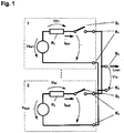
- FIG. 1 the equivalent circuit diagram of the parallel connection of a first lithium-ion battery 1 with further lithium-ion batteries is shown, with the clarity only a second lithium-ion battery 2 is shown in the figure.
- the invention and further advantageous refinements of the invention are described below by way of example using the parallel connection of lithium-ion batteries or lithium-ion accumulators.
- the invention is not limited to lithium-ion batteries and all designs can also be transferred to electrical storage devices of another type.
- the term battery also includes rechargeable batteries and accumulators.
- the lithium-ion batteries 1, 2 each have an open circuit voltage V Bat1 , V Bat2 , and an impedance R 1 , R 2 , across which a voltage V R1 , V R2 drops when the lithium-ion battery 1, 2 is loaded.
- the batteries 1, 2 are each provided with a switch S 1 , S 2 , by means of which one of the connection terminals K 1 , K 2 can be connected to or disconnected from the respective battery 1, 2 in a current-carrying manner.
- the connection terminals K 1 , K 2 are connected to external connections K e , to which an electrical consumer, for example an electric motor, is connected.
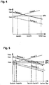
- the straight AP1 in Figure 2 represents the operating point at which the terminal voltage V Te has dropped so far that it corresponds to the open circuit voltage V Bat2 of the second battery 2.
- the connection differential voltage has been chosen to be zero.
- the voltage drop across the switch S 2 is zero and the switch S 2 can be closed without loss of power and without wear. Closing the Switch S 2 only lasts a few milliseconds. During this time, the consumer is controlled so that the flowing current remains constant.
- the second battery 2 does not yet supply any current to the load, since the corresponding current is zero for the current voltage ratio. Only when the load current increases further and thus the voltage V Te further decreases (for example working point AP2) does the current from both batteries 1, 2 increase by the same amount (see the course of the curves "Discharge 1" and "Discharge 2" in Figure 2 ). Since the internal resistance effective with respect to the load was halved by the parallel connection of both lithium-ion batteries 1, 2, the voltage drop per increase in power unit is only half as great as in the system which was operated with only one battery.
- the load current flowing to the consumer is the sum of the two battery currents. Since both lithium-ion batteries 1, 2 continue to be stressed differently, battery 1 is discharged more than battery 2, so that the open circuit voltages of both batteries 1, 2 equalize. The total current that can be supplied by the batteries 1, 2 is higher the further the open circuit voltages of the batteries 1, 2 are matched to one another, since the contribution of the second battery 2 increases proportionally. This adjustment occurs at clamping voltages V Te that are less than or equal to AP1, without charges being transported from battery 1 with a higher open circuit voltage to battery 2 with lower open circuit voltage.
- the method is used analogously for more than two batteries 1, 2, N.
- this is battery 1.
- Battery 1 is therefore first switched on and loaded. If the clamping voltage V Te has fallen to the open circuit voltage V Bat2 of the battery 2 with the second highest voltage, this is switched on. If the load increases further, the moment is waited at which the common clamping voltage V Te corresponds to the open circuit voltage V Bat3 of the battery 3 with the third highest voltage, so that it can also be switched on. This process can be repeated for any number N of batteries.
- this type of parallel connection of several batteries is also possible with non-zero connection differential voltages, but with increased stress on the switches.
- Active batteries are those batteries whose assigned switch is closed and which are electrically conductively connected to the external connections K e . If the power is reduced so that the external clamping voltage rises above one or more open circuit voltages of the already active batteries, the batteries whose open circuit voltage is below the terminal voltage are charged, the other batteries supply the current for this.
- FIG. 4 shows this for the case of two batteries 1, 2 connected in parallel. Both batteries 1, 2 were previously electrically connected to the external connections K e , ie the respective switches S 1 , S 2 were closed. This means that the terminal voltage had in the meantime dropped to at least the value of the open circuit voltage V Bat2 of the accumulator 2. After reducing the power drawn from the consumer, the terminal voltage V Te has risen again to the operating point AP4. The open circuit voltage V Bat2 of the battery 2 is then lower than the external terminal voltage V Te , the open circuit voltage V Bat1 of the battery 1 is higher than the external terminal voltage V Te . The battery 1 then supplies both current for the consumer and for charging the battery 2 and the original energy source battery 2 becomes an energy sink, ie a consumer. This charge equalization between batteries 1, 2 when the power is reduced offers the advantage that the maximum available current is reached more quickly.
- the charge equalization described above while reducing the power also has the disadvantage that additional losses occur as a result of the current flowing from battery 1 to battery 2.
- the faster charge equalization is therefore purchased, for example, when connecting an electric drive with a reduced range. It can therefore also be advantageous to withdraw consumer power and an associated increase in the external terminal voltage to switch off the battery or generally the memory, the open circuit voltage of which is below the external terminal voltage, that is to say to open the associated switch. In this case, after reducing the power, only those memories are connected in parallel and contribute to the power supply to the consumer whose open circuit voltage is greater than the current terminal voltage.
- a hysteresis is provided in order to avoid instability of the system in the area of the switchover point.
- Switching on and switching off the battery 2 or generally the memory does not take place at the same voltage, but at different voltages.
- the battery 2 is then switched on, ie connected in parallel, when the external terminal voltage V Te matches the open circuit voltage V Bat2 of the lithium-ion battery 2. This corresponds to the working point 5 in Figure 5 .
- the battery 2 is only switched off when the terminal voltage V Te is a certain value above the open circuit voltage V Bat2 of the lithium-ion battery 2. In the example according to Figure 5 this is the case with a terminal voltage corresponding to operating point 6.
- the terminal voltage V Te must therefore at least reach the open circuit voltage V Bat2 plus a certain switch-off differential voltage.
- the hysteresis can also be achieved, for example, in that the connection voltage is below the open circuit voltage of the memory to be switched on and the disconnection differential voltage is at the open circuit voltage of the memory to be switched off.
- the switch-on differential voltage when switching on the second memory 2 is negative and the switch-off differential voltage when switching off the second memory 2 is zero.
- the hysteresis is selected to be as small as possible and the hysteresis voltage difference is placed symmetrically around the open circuit voltage of the memory 2 to be switched on or off, so that the connection below the open circuit voltage and the disconnection above the open circuit voltage of the / memory 2 to be deactivated takes place.
- the switch-on differential voltage when switching on the second memory 2 and the switch-off differential voltage when switching off the second memory 2 preferably have the same amount, but are negative in the case of switching on or positive if the second memory 2 is switched off Figure 5 the hysteresis voltage difference corresponds to the difference of the voltages in the operating points AP5 and AP6. It is switched on in the working point AP5 and switched off in the working point AP6.
- the open circuit voltage can only be determined when the battery is not loaded. If the battery is removed from the charge or if the battery is charged, the open circuit voltage changes. This changes the optimal working point for switching off. To ensure that the switch current does not exceed the permissible limits when it is switched off, it makes sense to use a battery model to calculate the changing open circuit voltage when the battery is under load.
- the open circuit voltage of the battery to be switched off is preferably calculated using a battery model.
- the switching off of the switches can also be carried out via the differential voltage based on the measurement of the battery current.
- the switching off preferably takes place when the current through the switch to be actuated is zero or close to zero.
- the switching on and off of a current hysteresis should follow. Assuming that a motor current in which the battery absorbs energy, i.e. the battery is charged, counted positively or has a positive sign, the closing of the switch of the second memory takes place at lower current values than the opening of the switch.
- the switch is preferably closed and opened symmetrically to the zero current value.
- the battery with the lower energy is switched off when its current has become motorized by a certain value, ie when the battery begins to absorb energy, which happens when the open circuit voltage of the Battery is below the external clamping voltage.
- this procedure is changed in such a way that the battery with the higher charge is switched off when its current begins to regenerate by a certain value, ie the battery begins to supply energy.
- the circuit of the first electrical store and of the second electrical store advantageously has a current measuring device per store for detecting the current flowing from or to the store.
- the current determined by the current measuring device serves as a criterion for switching off the second memory.
- the current measuring device measures the sign of the current, that is to say it determines whether the current flows to the second memory or is drawn off from the second memory.
- the second memory is decoupled from the connection terminals.
- the amount of current from the current measuring device is also advantageously measured and the shutdown of the second memory is also regulated as a function of the amount of current.
- the second store can then be separated from the first store and the consumer when a certain minimum current flows from the first store to the second store.
- the second store then does not work more motor, but generator.
- the memory to be switched off is switched off at a specific motor current value.
Description
Die Erfindung betrifft ein Verfahren zum Parallelschalten eines ersten elektrischen nach Anspruch 1.The invention relates to a method for connecting a first electrical device in parallel according to
Die Nutzbarkeit nicht stationärer elektrischer Verbraucher, wie zum Beispiel elektrischer Antriebe, hängt wesentlich von der Kapazität des nutzbaren Speichers elektrischer Energie ab. Typische Energiespeicher für nicht stationäre Anwendungen sind elektrische Batterien, Akkumulatoren oder Kondensatoren.The usability of non-stationary electrical consumers, such as electrical drives, depends largely on the capacity of the usable storage of electrical energy. Typical energy stores for non-stationary applications are electrical batteries, accumulators or capacitors.
Für diese Klasse von Energiespeichem ist charakteristisch, dass der Ladezustand im unbelasteten Zustand mit einer bestimmten Klemmenspannung korreliert. Bei gleicher Speichertechnologie und gleichem Ladezustand korreliert das Volumen des Speichers linear mit der gespeicherten Energiemenge, das heißt je größer der Speicher, desto größer ist die darin gespeicherte Energie.It is characteristic of this class of energy stores that the state of charge correlates with a certain terminal voltage in the unloaded state. At the same Storage technology and the same state of charge correlate the volume of the storage linearly with the amount of energy stored, i.e. the larger the storage, the greater the energy stored in it.
Der maximale Energieinhalt eines Speichers hat neben Kostenaspekten auch mechanische Aspekte. Es dürfen unter Umständen bestimmte Abmessungen nicht überschritten werden, um den Einbau z.B. in einem Fahrzeug und den Transport des Speichers zu ermöglichen. Desweiteren sind auch der Gesamtmasse durch Erfordernisse, die sich aus der Handhabung und dem Transport ableiten, Grenzen gesetzt.The maximum energy content of a storage device has not only cost aspects but also mechanical aspects. Under certain circumstances, certain dimensions may not be exceeded in order to e.g. in a vehicle and to allow the storage to be transported. Furthermore, the total mass is also limited by requirements derived from handling and transportation.
Übersteigt der Gesamtenergiebedarf die Grenzen eines Speichers, die sich aus den Abmessungen und der Masse ableiten, müssen mehrere Speicher zusammengeschaltet werden. Die Notwendigkeit der Zusammenschaltung mehrerer Speicher zu einem großen Speicher kann sich auch aus dem verfügbaren Einbauraum ableiten.If the total energy requirement exceeds the limits of a store, which are derived from the dimensions and the mass, several stores must be interconnected. The necessity of interconnecting several memories to form a large memory can also be derived from the available installation space.
Handelt es sich beim Speicher um eine Batterie, ist diese aus Grundeinheiten, den Batteriezellen, aufgebaut. Der Energieinhalt einer Batteriezelle hängt von der Zellentechnologie und dem Zellenvolumen ab. Durch geeignete Wahl der Anzahl der Zellen und deren Zusammenschaltung zu sogenannten Core Packs kann der Energieinhalt und die Stromtragfähigkeit des Core Packs proportional zur Anzahl der Zellen gestaltet werden.If the storage is a battery, it is made up of basic units, the battery cells. The energy content of a battery cell depends on the cell technology and the cell volume. By a suitable choice of the number of cells and their interconnection to form so-called core packs, the energy content and the current carrying capacity of the core pack can be designed in proportion to the number of cells.
Durch ein geeignetes Verhältnis von Reihen- zu Parallelschaltung der Core Packs innerhalb einer Batterie ist desweiteren die Anpassung der Impedanz der Batterie an die Impedanz des Verbrauchers möglich, d.h. die Batterie kann so abgestimmt werden, dass sie in der Lage ist. auch den maximal benötigten Strom bei erforderlichem Energieinhalt zu liefern.A suitable ratio of series connection to parallel connection of the core packs within a battery furthermore makes it possible to adapt the impedance of the battery to the impedance of the consumer, i.e. the battery can be tuned to be able to. also to deliver the maximum required electricity with the required energy content.
Die Erhöhung des Energieinhaltes des Speichers kann durch Reihenschaltung und/oder Parallelschaltung mehrerer Batterien vorgenommen werden. Bei Reihenschaltung mehrerer Batterien ergeben sich jedoch durch die erhöhte Systemspannung höhere Anforderungen an die Isolation und an Kriech- und Luftstrecken, denen die Ausführung der Einzelbatterie häufig nicht entspricht, da deren Isolationssystem ausschließlich auf das Spannungsniveau des Einzelbetriebs abgestimmt ist.The energy content of the memory can be increased by connecting several batteries in series and / or in parallel. When several batteries are connected in series, however, the increased system voltage places higher demands on the insulation and on creepage distances and clearances, which the design of the individual battery often does not meet because of their Isolation system is tailored exclusively to the voltage level of individual operation.
Die Parallelschaltung mehrerer Batterien wird daher bei begrenzter Spannungsfestigkeit der Einzelbatterie oder der anzuschließenden Verbraucher als geeignetere Maßnahme zur Erhöhung des Energieinhaltes des Speichers betrachtet. Dies gilt auch bei Speichern bestehend aus Akkumulatoren oder Kondensatoren.The parallel connection of several batteries is therefore considered to be a more suitable measure for increasing the energy content of the storage when the individual battery or the consumers to be connected are of limited dielectric strength. This also applies to storage systems consisting of accumulators or capacitors.
Zur Erfüllung verschiedener Sicherheitsanforderungen sind elektrische Speicher mit einem Speicherschatter ausgestattet. Ist der Schalter deaktiviert, sind die zugängigen Speicheranschlüsse spannungsfrei.To meet various security requirements, electrical storage devices are equipped with a storage shader. If the switch is deactivated, the accessible memory connections are voltage-free.
Bei der Parallelschaltung von elektrischen Speichern werden Anschlüsse gleicher Polarität miteinander verbunden. Das ist unproblematisch, solange bei N Speichern mindestens N-1 Speicherschalter geöffnet sind.When electrical memories are connected in parallel, connections of the same polarity are connected to one another. This is not a problem as long as at least N-1 memory switches are open for N memories.
Für die Zeit, in denen die Speicher nicht mit der gemeinsamen Sammelschiene verbunden sind, kann sich ihre Spannungslage unterschiedlich entwickeln. Ursachen hierfür können zum Beispiel das separate Laden über unterschiedliche Zeiträume oder auch die unterschiedliche Eigenentladung bei Nichtbenutzen des Speichers über einen längeren Zeitraum sein.For the time when the storage devices are not connected to the common busbar, their voltage levels can develop differently. The reasons for this can be, for example, the separate charging over different periods or the different self-discharge when the storage is not used for a longer period.
Sind die Spannungen der Speicher unterschiedlich, fließt nach dem Zusammenschalten von zwei Speichern, das heißt nach dem Schließen der entsprechenden zwei Speicherschalter, ein Strom vom Speicher höherer Spannung zum Speicher niedrigerer Spannung, der solange einen Ladungsausgleich bewirkt, bis die Spannungen über beiden Speichern gleich sind. Dies gilt unter der Annahme, dass keine Last an die parallel geschalteten Speicher angeschlossen wurde, über der die Spannung kleiner als die Leerlaufspannung des Speichers mit der kleineren Ladung ist. Die Höhe des Stromflusses wird definiert durch die Spannungsdifferenz zwischen beiden Speichern und dem in Reihe liegenden Widerstand. Im Falle der Parallelschaltung zweier gleicher Speicher ist bezüglich des Ausgleichstromes der doppelte Innenwiderstand eines Speichers wirksam.If the voltages of the storage devices are different, a current flows from the storage device of higher voltage to the storage device of lower voltage after the interconnection of two storage devices, i.e. after the corresponding two storage switches have been closed, which causes a charge equalization until the voltages across both storage devices are equal . This applies on the assumption that no load has been connected to the parallel-connected storage device above which the voltage is less than the open circuit voltage of the storage device with the smaller charge. The amount of current flow is defined by the voltage difference between the two stores and the resistance in series. If two identical memories are connected in parallel, double the internal resistance of a memory is effective with regard to the equalizing current.
Der Ausgleichsstrom führt bei N parallel geschalteten Speichern an N-1 Speicherschaltern zu Einschaltverlusten, falls sich die Spannung der zuzuschaltenden Batterie von der Spannung der bereits zugeschalteten Batterie bzw. der resultierenden Spannung der bereits zugeschalteten Batterien unterscheidet. Wird der Schalter des ersten Speichers geschlossen, findet noch kein Stromfluss statt, da die Differenzspannung noch über dem zweiten Schalter abfällt. Wird nun der Schalter des zweiten Speichers geschlossen, kommt es bis zum Erreichen des stationären Durchlasswiderstandes des Schalters zu einer Verlustleistungsspitze, die sich als Produkt von Spannungsabfall über dem Schalter und wirksamem Ausgleichsstrom ergibt. Durch die auftretende Schaltverlustleistung kommt es zur Erosion der Schaltkontakte. Die Schalter müssen daher für einen maximal zu schaltenden Strom und den Charakter der Last spezifiziert werden. Der Ausgleichsstrom bewirkt am wirksamen Ersatzwiderstand der Speicher Verluste, so dass ein Teil der gespeicherten Energie während des Vorgangs des Ladungs- und damit Spannungsausgleichs in Wärme umgewandelt wird.In the case of N memories connected in parallel on N-1 memory switches, the compensating current leads to switch-on losses if the voltage of the battery to be connected differs from the voltage of the battery already connected or the resulting voltage of the batteries already connected. If the switch of the first memory is closed, there is still no current flow because the differential voltage still drops across the second switch. If the switch of the second memory is now closed, there is a power loss peak until the steady state resistance of the switch is reached, which results as a product of the voltage drop across the switch and the effective compensating current. The switching power dissipation leads to erosion of the switching contacts. The switches must therefore be specified for a maximum switchable current and the character of the load. The compensating current causes losses at the effective equivalent resistance of the storage, so that part of the stored energy is converted into heat during the charge and thus voltage equalization process.
Wenn zwei Lithium-Mangan-Batterien beispielsweise einen Innenwiderstand von je 1 mOhm haben und sich bei der Parallelschaltung dieser Batterien deren Batteriespannungen um beispielsweise 10 Volt unterscheidet, so fließt aufgrund des sehr geringen Innenwiderstands ein Ausgleichsstrom von 5000 A, der ein hohes Gefahrenpotential darstellen kann.If, for example, two lithium-manganese batteries have an internal resistance of 1 mOhm each, and when these batteries are connected in parallel, their battery voltages differ by, for example, 10 volts, a compensating current of 5000 A flows due to the very low internal resistance, which can represent a high hazard potential.
Aus der
Die
In der
Aufgabe vorliegender Erfindung ist es, ein Verfahren zur Parallelschaltung von zwei oder mehr elektrischen Speichern und eine entsprechende Schaltung vorzuschlagen, welche das Parallelschalten von Speichern unterschiedlicher Leerlaufspannung bei minimierter Beanspruchung der beteiligten Schalter ermöglichen, wobei der Ladungsausgleich zwischen den Speichern minimiert oder völlig verhindert wird. Beim Zusammenschalten zweier Speicher fließende Ausgleichsströme sollen vermieden oder möglichst auf ein Minimum begrenzt werden.The object of the present invention is to propose a method for the parallel connection of two or more electrical stores and a corresponding circuit which enable the parallel connection of stores with different open circuit voltages while minimizing the stress on the switches involved, the charge equalization between the stores being minimized or completely prevented. At the Interconnection of two equalizing currents flowing through the storage should be avoided or minimized as far as possible.
Eine weitere Aufgabe ist es, ein Verfahren und eine Schaltung aufzuzeigen, welche eine Parallelschaltung zweier elektrischer Speicher ohne oder mit nur geringer Unterbrechung der Leistungsentnahme erlauben.Another object is to demonstrate a method and a circuit which allow two electrical memories to be connected in parallel with little or no interruption in power consumption.
Alle oder zumindest ein Teil dieser Aufgaben werden durch ein Verfahren nach Anspruch 1 gelöst. Hierdurch wird zum Beispiel bei Ladungsentnahme die elektrische Verbindung zwischen dem ersten Speicher und den Anschlussklemmen mittels des ersten Schalters hergestellt und die elektrische Verbindung zwischen dem zweiten Speicher und den Anschlussklemmen mittels des zweiten Schalters unterbrochen wird, so dass zunächst nur dem ersten Speicher Ladung entnommen wird, und dass die elektrische Verbindung zwischen dem zweiten Speicher und den Anschlussklemmen mittels des zweiten Schalters hergestellt wird, wenn die Differenz der an den Anschlussklemmen des ersten Speichers abfallenden Spannung und der Leerlaufspannung des zweiten Speichers weniger als eine vorgegebene Zuschalt-Differenzspannung beträgt.All or at least part of these tasks are solved by a method according to
Eine erfindungsgemäße Schaltung eines ersten elektrischen Speichers und eines zweiten elektrischen Speichers wird in Anspruch 10 offenbart.A circuit according to the invention of a first electrical store and a second electrical store is disclosed in claim 10.
Vorzugsweise wird bei Ladungszufuhr genau umgekehrt vorgegangen: Bei Ladungszufuhr wird zunächst die elektrische Verbindung zwischen dem zweiten Speicher und den Anschlussklemmen mittels des zweiten Schalters hergestellt und die elektrische Verbindung zwischen dem ersten Speicher und den Anschlussklemmen mittels des ersten Schalters unterbrochen, so dass zunächst nur dem zweiten Speicher Ladung zugeführt wird. Die elektrische Verbindung zwischen dem ersten Speicher und den Anschlussklemmen wird mittels des ersten Schalters erst dann hergestellt, wenn die Differenz der an den Anschlussklemmen des zweiten Speichers abfallenden Spannung und der Leerlaufspannung des ersten Speichers weniger als eine vorgegebene Abschalt-Differenzspannung beträgt.The procedure for supplying the charge is preferably reversed: when the charge is supplied, the electrical connection between the second store and the connection terminals is first established using the second switch and the electrical connection between the first store and the connection terminals is interrupted using the first switch, so that initially only the second one Storage charge is supplied. The electrical connection between the first memory and the connection terminals is only established by means of the first switch when the difference between the voltage drop across the connection terminals of the second memory and the open circuit voltage of the first memory is less than a predetermined switch-off differential voltage.
Mittels der Messgeräte können die momentane Klemmenspannung des oder der Speicher, die bereits mit der Last verbunden sind, und die Leerlaufspannung des als nächstes zuzuschaltenden Speichers erfasst werden. Diese Werte werden in der Steuereinheit miteinander verglichen. Wenn diese beiden Werte eine vorgegebene Bedingung erfüllen, insbesondere wenn diese voneinander um nicht mehr als eine vorgegebene Zuschalt-Differenzspannung oder Abschalt-Differenzspannung abweichen, steuert die Steuereinheit den Schalter des zuzuschaltenden oder abzuschaltenden Speichers an, um diesen zu schließen oder zu öffnen. Die erfindungsgemäße Schaltung erlaubt damit die Parallelschaltung des ersten oder zweiten Speichers zu einem gemeinsamen Speicher oder die Abkopplung des ersten oder zweiten Speichers aus einer bestehenden Parallelschaltung in Abhängigkeit von der Klemmenspannung und der Leerlaufspannung des ersten oder zweiten Speichers. Mit dem Begriff Speicher ist im Folgenden ein Speicher zur Speicherung elektrischer Energie gemeint. Insbesondere wird unter einem Speicher eine Batterie, ein Akkumulator oder ein Kondensator verstanden. Entsprechend dem allgemeinen Sprachgebrauch soll im Rahmen dieser Anmeldung der Begriff Batterie auch Akkumulatoren und wiederaufladbare Batterien umfassen. Die Erfindung wird mit besonderem Vorteil zur Parallelschaltung von Lithium-Ionen-Akkumulatoren, insbesondere Lithium-Mangan-Akkumulatoren. eingesetzt, da diese Batterien- bzw. Akkumulatorentypen einen geringen Innenwiderstand aufweisen, so dass ohne Einsatz der Erfindung bei der Parallelschaltung dieser Batterien/Akkumulatoren hohe Ströme fließen könnten. Insbesondere eignet sich die Erfindung zur Parallelschaltung von Speichern, insbesondere Batterien oder Akkumulatoren, mit gleicher Nennspannung.The instantaneous terminal voltage of the memory or memories, which are already connected to the load, and the open circuit voltage of the memory to be connected next can be detected by means of the measuring devices. These values are compared with one another in the control unit. If these two values meet a predefined condition, in particular if they differ from one another by no more than a predefined switch-on differential voltage or switch-off differential voltage, the control unit controls the switch of the memory to be switched on or off in order to close or open it. The circuit according to the invention thus allows the parallel connection of the first or second memory to a common memory or the decoupling of the first or second memory from an existing parallel circuit depending on the terminal voltage and the open circuit voltage of the first or second memory. In the following, the term storage means a storage for storing electrical energy. In particular, a memory is understood to mean a battery, an accumulator or a capacitor. According to the general usage in the context of this application, the term battery should also include accumulators and rechargeable batteries. The invention is particularly advantageous for the parallel connection of lithium-ion batteries, in particular lithium-manganese batteries. used because these types of batteries or accumulators have a low internal resistance, so that no use of the invention, high currents could flow when these batteries were connected in parallel. In particular, the invention is suitable for the parallel connection of memories, in particular batteries or accumulators, with the same nominal voltage.
Unter dem Begriff Anschlussklemmen werden die Anschlüsse des Speichers verstanden, über die dem Speicher Ladung entnommen oder zugeführt werden kann. Der Begriff Klemmenspannung kennzeichnet die an diesen Anschlussklemmen anliegende Spannung.The term connection terminals is understood to mean the connections of the memory via which charge can be drawn or supplied to the memory. The term terminal voltage denotes the voltage applied to these connection terminals.
Erfindungsgemäß ist in einer der elektrischen Verbindungsleitungen zwischen dem Speicher und den Anschlussklemmen ein Schalter vorgesehen. Wenn der Schalter geöffnet ist, das heißt die elektrische Verbindung zwischen dem Speicher und einer der Anschlussklemmen unterbrochen ist, entspricht die zwischen den beiden elektrischen Verbindungsleitungen speicherseitig des Schalters abfallende Spannung, das heißt die zwischen dem den Speicher und den Schalter verbindenden Teilstück der einen elektrischen Verbindungsleitung und der anderen elektrischen Verbindungsleitung abfallende Spannung, der Leerlaufspannung des Speichers. Bei geschlossenem Schalter entspricht diese Spannung der Klemmenspannung. Klemmenspannung und Leerlaufspannung können also mit demselben Messgerät bestimmt werden, wobei im ersten Fall der Schalter geschlossen, im zweiten Fall der Schalter geöffnet ist.According to the invention, a switch is provided in one of the electrical connecting lines between the memory and the connection terminals. When the switch is open, that is to say the electrical connection between the memory and one of the connection terminals is interrupted, the voltage drop between the two electrical connecting lines on the memory side of the switch corresponds, that is to say that between the section connecting the memory and the switch to the one electrical connecting line and the other voltage drop, the open circuit voltage of the memory. When the switch is closed, this voltage corresponds to the terminal voltage. Terminal voltage and open circuit voltage can thus be determined with the same measuring device, the switch being closed in the first case and the switch being open in the second case.
Der Schalter stellt die elektrische Verbindung zwischen dem zugeordneten Speicher und dessen Anschlussklemmen her oder unterbricht diese. Bei geöffnetem Schalter sind der Speicher und die an die Verbindungsleitung mit dem Schalter angeschlossene Anschlussklemme elektrisch voneinander entkoppelt, d.h. es besteht keine stromleitende Verbindung. Auch parallel zu der elektrischen Verbindungsleitung, in der der Schalter angeordnet ist, besteht keine elektrische Verbindung zwischen dem Speicher und der entsprechenden Anschlussklemme. Bei geöffnetem Schalter ist daher die Verbindung zwischen dem Speicher und der Anschlussklemme komplett unterbrochen. Insbesondere sind keine parallel oder anti-parallel zu dem Schalter angeordnete Diode, wie zum Beispiel eine parasitäre Diode, oder ein Widerstand vorgesehen, über die unter bestimmten Voraussetzungen Strom fließen könnte.The switch establishes or interrupts the electrical connection between the assigned memory and its connection terminals. When the switch is open, the memory and the connection terminal connected to the connecting line with the switch are electrically decoupled from one another, i.e. there is no current-carrying connection. Even parallel to the electrical connection line in which the switch is arranged, there is no electrical connection between the memory and the corresponding connection terminal. When the switch is open, the connection between the memory and the connection terminal is therefore completely interrupted. In particular, there are no diodes arranged in parallel or anti-parallel to the switch, such as a parasitic diode, or a resistor, via which current could flow under certain conditions.
Erfindungswesentlich ist es, dass bei Ladungsentnahme die Angleichung der Spannungen der einzelnen Speicher durch Belastung des ersten Speichers, d.h. des zuerst mit der Last verbundenen Speichers, herbeigeführt wird. Umgekehrt erfolgt beim Laden der Speicher die Angleichung der Spannungen der einzelnen Speicher durch Ladung des zweiten Speichers, der in diesem Fall zuerst mit der Quelle verbunden wird. Die Spannungsangleichung erfolgt nicht über einen Vorladewiderstand, der beispielsweise zwischen den ersten und den zweiten Speicher geschaltet werden könnte, sondern durch Belastung oder Ladung des zuerst mit der Senke oder Quelle verbundenen Speichers. Erfindungsgemäß sind parallel zu dem Schalter weder Vorladewiderstände noch Dioden oder ähnliche Bauteile vorgesehen. Der Speicher wird entweder direkt mit den Anschlussklemmen verbunden (bei geschlossenem Schalter) oder völlig von den Anschlussklemmen getrennt (bei geöffnetem Schalter). Auf diese Weise wird die Verlustleistung bei der Parallelschaltung von Speichern möglichst niedrig gehalten.It is essential to the invention that when the charge is withdrawn, the voltages of the individual stores are equalized by loading the first store, ie the storage associated with the load. Conversely, when the memories are loaded, the voltages of the individual memories are equalized by charging the second memory, which in this case is first connected to the source. The voltage adjustment does not take place via a precharge resistor, which could be connected, for example, between the first and the second store, but rather by loading or charging the store connected first to the sink or source. According to the invention, neither precharging resistors nor diodes or similar components are provided in parallel with the switch. The memory is either connected directly to the connection terminals (when the switch is closed) or completely separated from the connection terminals (when the switch is open). In this way, the power loss is kept as low as possible when connecting memories in parallel.
Als Impedanz eines Speichers wird dessen elektrischer Widerstand bezeichnet, wobei die Impedanz sowohl dynamische als auch statische Anteile besitzen kann. Im stationären Betrieb entspricht die Impedanz dem Innenwiderstand des Speichers. Stationärer Betrieb bedeutet hierbei, dass über mehrere Millisekunden ein konstanter Strom geliefert wird und die in dieser Zeit auftretende Temperaturänderung des Speichers vernachlässigbar ist.The electrical resistance of a memory is called the impedance, whereby the impedance can have both dynamic and static components. In stationary operation, the impedance corresponds to the internal resistance of the memory. Stationary operation means that a constant current is supplied over several milliseconds and the temperature change of the storage that occurs during this time is negligible.
Unter den Begriffen Verbraucher oder Last wird ein elektrischer Verbraucher, insbesondere ein elektrischer Motor, verstanden, der aus dem oder den Speichern mit elektrischer Energie versorgt wird. Im weiteren Sinn kann es sich aber auch um eine Last handeln, die keinen Strom verbraucht, sondern die dem oder den Speichern Ladung zuführt. Sofern letztere Bedeutung gemeint ist, wird im Folgenden ausdrücklich darauf hingewiesen.The terms consumer or load mean an electrical consumer, in particular an electric motor, which is supplied with electrical energy from the store or stores. In a broader sense, however, it can also be a load that does not consume electricity, but instead supplies the storage device with charge. If the latter meaning is meant, it is expressly pointed out below.
Beispielsweise werden die Speicher in Abhängigkeit von ihren Leerlaufspannungen zugeschaltet. Bei Ladungsentnahme wird zunächst nur dem ersten Speicher mit der höheren Leerlaufspannung Ladung entnommen. Die Angleichung der Klemmenspannung des bereits zugeschalteten ersten Speichers an die Leerlaufspannung des zweiten Speichers passiert im Wesentlichen durch den Spannungsabfall über dem Innenwiderstand des zuerst zugeschalteten ersten Speichers. Für den Fall, dass der Laststrom nicht hoch genug ist, um einen hinreichenden Spannungsabfall zu bewirken, kommt es über die Zeit zu einem Angleichen der Leerlaufspannungen durch Entladen des ersten Speichers.For example, the memories are switched on depending on their open circuit voltages. When removing the charge, only the first storage with the higher open circuit voltage is removed. The adjustment of the terminal voltage of the first memory already connected to the open circuit voltage of the second memory essentially occurs due to the voltage drop across the internal resistance of the first memory connected first. In the event that the load current is not high enough to get one To cause a sufficient voltage drop, the open-circuit voltages are adjusted over time by discharging the first memory.
In der Praxis wird diese Schaltung vorzugsweise dadurch realisiert, dass pro Speicher ein Schalter und ein Spannungsmessgerät vorgesehen sind. Der Schalter ist in einer der elektrischen Verbindungen zwischen dem Speicher und einer der Anschlussklemmen des Speichers angeordnet. Das Spannungsmessgerät misst die Spannung zwischen der Speicherseite des Schalters, d.h. zwischen dem Teilstück, welches den Speicher und den zugehörigen Schalter verbindet, und der anderen Anschlussklemme des Speichers, die direkt ohne Zwischenschaltung eines Schalters mit dem Speicher verbunden ist. Wenn der Schalter geöffnet ist und damit der entsprechende Speicher von den bzw. von einer der Anschlussklemmen getrennt ist, misst das Spannungsmessgerät die Leerlaufspannung des Speichers. Dies wird dadurch gewährleistet, dass parallel zu der den Schalter aufweisenden elektrischen Verbindungsleitung keine weitere elektrische Verbindungsleitung vorgesehen ist. Wenn der Schalter geschlossen ist, misst das Spannungsmessgerät die Klemmenspannung des Speichers. Wenn keine Last an die Anschlussklemmen angeschlossen ist, stimmen Leerlaufspannung und Klemmenspannung überein.In practice, this circuit is preferably implemented in that a switch and a voltage measuring device are provided per memory. The switch is arranged in one of the electrical connections between the memory and one of the connection terminals of the memory. The voltage measuring device measures the voltage between the memory side of the switch, i.e. between the section that connects the memory and the associated switch, and the other connection terminal of the memory, which is connected directly to the memory without the interposition of a switch. When the switch is open and the corresponding memory is separated from or from one of the connection terminals, the voltage measuring device measures the open circuit voltage of the memory. This is ensured by the fact that no further electrical connection line is provided parallel to the electrical connection line having the switch. When the switch is closed, the voltage measuring device measures the terminal voltage of the memory. If no load is connected to the connection terminals, the open circuit voltage and the terminal voltage match.
Die Zuschalt-Differenzspannungen beim Entladevorgang und die Zuschalt-Differenzspannungen beim Ladevorgang können unabhängig voneinander gewählt werden. Beide Werte können sowohl positiv, negativ als auch Null sein. Je weiter die Zuschalt-Differenzspannung dem Wert Null angenähert wird, umso weiter konvergiert auch der Ausgleichstrom gegen Null und umso geringer ist die Beanspruchung des Schalters, der das Parallelschalten realisiert. Beim Entladen wird im Fall einer positiven Zuschalt-Differenzspannung der zweite Speicher parallel geschaltet, wenn die äußere Klemmenspannung, d.h. die Spannung zwischen den Klemmen, an die die Last angeschlossen ist, auf einen Wert gefallen ist, der der Leerlaufspannung des zweiten Speichers plus dem Betrag der Zuschalt-Differenzspannung entspricht. Umgekehrt wird bei einer negativen Zuschalt-Differenzspannung der zweite Speicher parallel geschaltet, wenn die äußere Klemmenspannung auf einen Wert gefallen ist, der der Leerlaufspannung des zweiten Speichers minus dem Betrag der Zuschalt-Differenzspannung entspricht. Für die beim Ladevorgang gewählte Zuschalt-Differenzspannung gilt Entsprechendes.The switch-on differential voltages during the discharge process and the switch-on differential voltages during the charging process can be selected independently of one another. Both values can be positive, negative or zero. The closer the differential voltage is to the value zero, the more the equalizing current converges to zero and the less the switch, which realizes the parallel connection, is subjected to less stress. When discharging, in the case of a positive switch-on differential voltage, the second memory is connected in parallel if the external terminal voltage, that is to say the voltage between the terminals to which the load is connected, has fallen to a value which is the no-load voltage of the second memory plus the amount corresponds to the connection differential voltage. Conversely, with a negative switch-on differential voltage, the second memory is connected in parallel if the external terminal voltage has dropped to a value which corresponds to the open circuit voltage of the second memory minus the amount of the switch-on differential voltage. The same applies to the connection differential voltage selected during the charging process.
Das Parallelschalten zweier elektrischer Speicher erfolgt dann optimal, wenn der Spannungsunterschied zum Zeitpunkt des Parallelschaltvorganges Null oder zumindest minimal ist. Je kleiner der Spannungsunterschied zwischen den Energiespeichern ist, umso kleiner ist der Spannungsabfall über dem zuletzt schließenden Schalter und umso geringer ist auch der zu erwartende Ausgleichsstrom, so dass sich die Verringerung des Spannungsunterschiedes quadratisch bezüglich der Reduzierung der Schalterverluste und damit auch bezüglich der Reduzierung des Schalterverschleißes auswirkt.The parallel connection of two electrical memories takes place optimally when the voltage difference at the time of the parallel switching process is zero or at least minimal. The smaller the voltage difference between the energy stores, the smaller the voltage drop across the last closing switch and the lower the expected compensating current, so that the reduction in the voltage difference squares with respect to the reduction in switch losses and thus also with regard to the reduction in switch wear affects.
Beim Parallelschalten zweier elektrischer Speicher wird erfindungsgemäß zunächst der Speicher mit der höheren Leerlaufspannung an den elektrischen Verbraucher bzw. die Last angeschlossen.When two electrical storage devices are connected in parallel, the storage device with the higher open circuit voltage is first connected to the electrical consumer or the load.
Die Ermittlung der Leerlaufspannung eines Speichers kann bei nicht mit dem Speicher verbundener Last beispielsweise durch Messung der an den Anschlussklemmen des Speichers anliegenden Klemmenspannung erfolgen. Da ohne Last kein Strom fließt, kommt es am Innenwiderstand bzw. an der Impedanz des Speichers zu keinem Spannungsabfall, so dass die Klemmenspannung gleich der Leerlaufspannung des Speichers ist.The open circuit voltage of a memory can be determined when the load is not connected to the memory, for example by measuring the terminal voltage applied to the connection terminals of the memory. Since no current flows without load, there is no voltage drop at the internal resistance or the impedance of the memory, so that the terminal voltage is equal to the open circuit voltage of the memory.
Ist der Speicher mit einer Last verbunden, kann die Leerlaufspannung aus der Klemmenspannung und der über dem Innenwiderstand des Speichers abfallenden Spannung bestimmt werden. Letzterer Spannungsabfall kann beispielsweise bei Kenntnis des Innenwiderstandes aus dem momentanen Stromfluss errechnet werden. In einer bevorzugten Ausführungsform ist daher ein Strommessgerät zur Erfassung des von oder zu dem ersten und/oder zweiten Speicher fließenden Stroms vorgesehen.If the memory is connected to a load, the open circuit voltage can be determined from the terminal voltage and the voltage dropping across the internal resistance of the memory. The latter voltage drop can, for example, be calculated from the current flow when the internal resistance is known. In a preferred embodiment, therefore, a current measuring device is provided for detecting the current flowing from or to the first and / or second memory.
Nach dem Anschließen der Last an den ersten Speicher und gegebenenfalls nach dem Einschalten der Last wird dem ersten Speicher Ladung entzogen. Je nach aufgenommener Leistung und daraus resultierendem Strom tritt an der Impedanz des ersten Speichers ein Spannungsabfall auf, um den sich die Klemmenspannung gegenüber der Leerlaufspannung des ersten Speichers vermindert. In dieser Phase wird die Last ausschließlich über den ersten Speicher mit elektrischer Energie versorgt.After the load has been connected to the first store and, if necessary, after the load has been switched on, charge is withdrawn from the first store. Depending on the power consumed and the resulting current, a voltage drop occurs at the impedance of the first memory, by which the terminal voltage is reduced compared to the open circuit voltage of the first memory. In this phase, the load is supplied with electrical energy exclusively via the first storage.
Neben der Annäherung der Klemmenspannung des ersten Speichers an die Leerlaufspannung des zweiten Speichers durch den Spannungsabfall über dem Innenwiderstand des ersten Speichers wird auch erreicht, dass sich der erste Speicher, der den Strom liefert, entlädt, so dass sich die Leerlaufspannungen des ersten und des zweiten Speichers mit der Zeit angleichen.In addition to the approximation of the terminal voltage of the first memory to the open circuit voltage of the second memory due to the voltage drop across the internal resistance of the first memory, it is also achieved that the first memory, which supplies the current, discharges, so that the open circuit voltages of the first and the second Align memory over time.
Wird der erste Speicher hinreichend hoch belastet, d.h. es wird dem ersten Speicher genügend Strom entnommen, kann sich die an den Anschlussklemmen des ersten Speichers abfallende Spannung an die Leerlaufspannung des zweiten Speichers um weniger als eine vorgegebene Zuschalt-Differenzspannung annähern.If the first storage is loaded sufficiently high, i.e. sufficient current is drawn from the first memory, the voltage drop across the connection terminals of the first memory can approach the open circuit voltage of the second memory by less than a predetermined switch-on differential voltage.
Wenn sich die Klemmenspannung des ersten Speichers und die Leerlaufspannung des zweiten Speichers bis auf die Zuschalt-Differenzspannung angeglichen haben, kann der zweite Speicher mit nur geringer Verlustleistung und ohne größere Belastung der Schalter parallel zum ersten Speicher geschaltet werden, so dass die Last in der Folge mit Energie aus dem ersten und dem zweiten Speicher versorgt wird.If the terminal voltage of the first memory and the open circuit voltage of the second memory have equalized up to the switch-on differential voltage, the second memory can be connected in parallel with the first memory with only a low power loss and without great stress on the switches, so that the load follows is supplied with energy from the first and the second storage.
Für die Speicher ist unter Umständen ein maximal zulässiger Strom definiert. Wird dieser überschritten, besteht die Gefahr, dass der Speicher geschädigt wird. Von Vorteil Ist daher eine Steuerung vorgesehen, welche dafür sorgt, dass der aus den Speichern abgezogene Strom den maximalen Strom des jeweiligen Speichers nicht übersteigt. Dies ist insbesondere in der ersten Phase, in der der Strom ausschließlich vom ersten Speicher geliefert wird, von Bedeutung. Von Vorteil wird daher überwacht, dass der Strom nicht den Maximalstrom der angeschlossenen Speicher, insbesondere des ersten Speichers, überschreitet.A maximum permissible current may be defined for the storage tanks. If this is exceeded, there is a risk that the memory will be damaged. It is therefore advantageous to have a controller which ensures that the current drawn from the memories does not exceed the maximum current of the respective memory. This is particularly important in the first phase, in which the electricity is supplied exclusively by the first storage device. It is therefore advantageously monitored that the current does not exceed the maximum current of the connected memories, in particular of the first memory.
Der zweite Speicher wird durch Schließen eines Schalters parallel zum ersten Speicher geschaltet Da der Schalter für den Schließvorgang eine bestimmte Zeit benötigt, ist es günstig, wenn der aus dem ersten Speicher abgezogene Strom, bei dem der Spannungsabfall am Innenwiderstand des ersten Speichers den gewünschten Wert hat, während des Schaltvorgangs konstant gehalten wird. Da die hierfür benötigte Zeit im Millisekundenbereich liegt, ist beispielsweise bei der Versorgung eines elektrischen Antriebs eine entsprechende Verzögerung Im Antriebsstrang eines Fahrzeuges nicht spürbar.The second memory is connected in parallel to the first memory by closing a switch. Since the switch takes a certain time to close, it is advantageous if the current drawn from the first memory at which the voltage drop across the internal resistance of the first memory has the desired value , is kept constant during the switching process. Since the time required for this is in the millisecond range, a corresponding delay is not noticeable in the drive train of a vehicle, for example when supplying an electric drive.
Bei weiterer Erhöhung des Laststromes wird auch dem zweiten Speicher Ladung entzogen. Unter der Annahme identischer Speicher mit gleichen Temperaturen und gleichem Erholungszustand nimmt der Strom aus dem ersten Speicher um den gleichen Betrag zu wie der Strom aus dem zweiten Speicher. Beide Speicher werden aber weiterhin unterschiedlich stark beansprucht, so dass der erste Speicher stärker als der zweite Speicher entladen wird und sich die Leerlaufspannungen beider Speicher angleichen.If the load current is increased further, charge is also withdrawn from the second store. Assuming identical stores with the same temperatures and the same state of recovery, the current from the first store increases by the same amount as the current from the second store. However, both stores are still used to different extents, so that the first store is discharged more than the second store and the open circuit voltages of both stores equalize.
Bei Reduzierung der Verbraucherleistung sinkt der Strom und die Klemmenspannung, d.h. die Spannung zwischen den Anschlussklemmen, an die die Last angeschlossen ist, erhöht sich. Wenn die Klemmenspannung wieder größer als die Leerlaufspannung des zweiten Speichers wird, ist es sowohl möglich, die Parallelschaltung von erstem und zweitem Speicher beizubehalten als auch den zweiten Speicher abzuschalten, das heißt, die stromleitende Verbindung zwischen den äußeren Anschlussklemmen, an die die Last angeschlossen ist, und dem zweiten Speicher zu unterbrechen. Das Abschalten des zweiten Speichers erfolgt vorzugsweise dann, wenn die Klemmenspannung sich um eine bestimmte Abschalt-Differenzspannung von der Leerlaufspannung des zweiten Speichers unterscheidet und/oder wenn der zweite Speicher aufgrund der sich ändernden Lastverhältnisse nur noch einen vernachlässigenden oder keinen Betrag zur Speisung der Last leistet oder wenn der zweite Speicher sogar beginnt, Energie aufzunehmen.When the consumer power is reduced, the current and the terminal voltage decrease, i.e. the voltage between the terminals to which the load is connected increases. If the terminal voltage again becomes greater than the open circuit voltage of the second memory, it is possible to maintain the parallel connection of the first and second memory as well as to switch off the second memory, i.e. the current-conducting connection between the external connection terminals to which the load is connected , and to interrupt the second memory. The second memory is preferably switched off when the terminal voltage differs from the open circuit voltage of the second memory by a specific switch-off differential voltage and / or when the second memory only makes a negligible or no amount to supply the load due to the changing load conditions or if the second store even begins to absorb energy.
Da der zweite Speicher in dieser Situation mit der Last verbunden ist, kann dessen Leerlaufspannung nicht direkt gemessen werden. Die Leerlaufspannung wird daher von Vorteil aus der Klemmenspannung und der über dem Innenwiderstand des Speichers abfallenden Spannung bestimmt. Letzterer Spannungsabfall kann beispielsweise bei Kenntnis des Innenwiderstandes aus dem momentanen Stromfluss errechnet werden.Since the second memory is connected to the load in this situation, its open circuit voltage cannot be measured directly. The open circuit voltage is therefore advantageously determined from the terminal voltage and the voltage drop across the internal resistance of the memory. The latter voltage drop can, for example, be calculated from the current flow when the internal resistance is known.
Eine andere Möglichkeit, den Abschaltzeitpunkt des zweiten Speichers zu bestimmen, besteht darin, den Strom von bzw. zu dem zweiten Speicher zu messen und den zweiten Speicher dann abzuschalten, wenn dieser Strom einen vorgegebenen Maximalstrom unterschreitetAnother possibility of determining the switch-off time of the second memory consists in measuring the current from or to the second memory and then switching off the second memory when this current falls below a predetermined maximum current
Auch beim Abschalten ist es günstig, den Strom während des Abschaltens des zweiten Speichers konstant zu halten.Even when switching off, it is advantageous to keep the current constant while switching off the second store.
Das Abschalten eines Speichers wird jedoch frühestens dann stattfinden, wenn der Gesamtstrom den zulässigen Strom eines einzelnen Schalters bzw. Speichers nicht mehr übersteigt. Eine zeitige Abschaltung des zweiten Speichers unmittelbar nachdem die Klemmenspannung die Leerlaufspannung des zweiten Speichers überschritten hat verhindert Verluste, die aus dem Ladungsausgleich zwischen den Speichern resultieren würden.However, switching off a memory will only take place at the earliest when the total current no longer exceeds the permissible current of an individual switch or memory. A timed shutdown of the second memory immediately after the terminal voltage has exceeded the open circuit voltage of the second memory prevents losses that would result from the charge equalization between the memories.
Von Vorteil erfolgt die Zuschaltung der einzelnen Speicher spannungsabhängig und deren Abschaltung stromabhängig. Der zweite Speicher wird dann zugeschaltet, wenn die Differenz der an den Anschlussklemmen des ersten mit der Last bereits verbundenen Speichers abfallenden Spannung und der Leerlaufspannung des zweiten Speichers weniger als eine vorgegebene Zuschalt-Differenzspannung beträgt. Umgekehrt wird die Abschaltung, d.h. Trennung eines Speichers von der Last, vorzugsweise stromabhängig durchgeführt. Bei Lastreduzierung wird der zweite Speicher vorzugsweise dann abgetrennt, d.h. der zugeordnete zweite Schalter wird geöffnet, wenn der Strom von bzw. zu dem zweiten Speicher einen vorgegebenen Wert unterschreitet.The individual memories are advantageously switched on in a voltage-dependent manner and switched off in a current-dependent manner. The second memory is switched on when the difference between the voltage drop across the connection terminals of the first memory already connected to the load and the open circuit voltage of the second memory is less than a predetermined switch-on differential voltage. Conversely, the shutdown, i.e. Separation of a memory from the load, preferably carried out depending on the current. When the load is reduced, the second store is then preferably disconnected, i.e. the assigned second switch is opened when the current from or to the second memory falls below a predetermined value.
In einer weiteren bevorzugten Ausführungsform werden Signale mit einer Lastschaltung ausgetauscht, welche zur Steuerung oder Regelung der Last dient, die von dem ersten und/oder zweiten Speicher mit Ladung versorgt wird. Die Signale von der Lastschaltung werden zumindest mitgenutzt, um während des Zu- oder Abschaltens des ersten oder zweiten Speichers den zu oder von den Speicher(n) fließenden Strom konstant zu halten. Während der Schaltvorgänge wird der Laststrom in Abhängigkeit von diesen Signalen und gegebenenfalls in Abhängigkeit von weiteren Größen konstant gehalten.In a further preferred embodiment, signals are exchanged with a load circuit which serves to control or regulate the load which is supplied with charge by the first and / or second memory. The signals from the load circuit are used at least in order to keep the current flowing to or from the memory (s) constant while the first or second memory is switched on or off. During the switching operations, the load current is kept constant depending on these signals and possibly depending on other variables.
Um eine Instabilität des Systems im Bereich des Umschaltpunktes zu vermeiden, ist es günstig, eine Hysterese vorzusehen. Zuschaltung und Abschaltung des Speichers werden bei unterschiedlichen Spannungen durchgeführt. Das heißt die Zuschalt-Differenzspannung beim Zuschalten eines Speichers unterscheidet sich von der Abschalt-Differenzspannung beim Abschalten des Speichers.In order to avoid instability of the system in the area of the switchover point, it is expedient to provide a hysteresis. The memory is switched on and off at different voltages. This means that the switch-on differential voltage when switching on a memory differs from the switch-off differential voltage when switching off the memory.
Der erste Speicher oder der zweite Speicher können jeweils mehrere parallel geschaltete Speicher aufweisen, die vorzugsweise in analoger Weise parallelgeschaltet werden oder wurden. Das heißt, das erfindungsgemäße Verfahren kann auch mit Vorteil bei mehr als zwei Speichern angewendet werden. Zuerst wird ermittelt, welcher Speicher die höchste Leerlaufspannung hat. Dieser Speicher wird im Sinne der Erfindung als erster Speicher angesehen und zuerst eingeschaltet und belastet. Weicht die Klemmenspannung dieses ersten Speichers um weniger als die Zuschalt-Differenzspannung von der Leerlaufspannung des Speichers mit der zweithöchsten Leerlaufspannung ab, wird der zweite Speicher eingeschaltet.The first memory or the second memory can each have a plurality of memories connected in parallel, which are or were preferably connected in parallel in an analog manner. This means that the method according to the invention can also advantageously be used with more than two memories. First, it is determined which memory has the highest open circuit voltage. In the sense of the invention, this memory is regarded as the first memory and is first switched on and loaded. If the terminal voltage of this first memory deviates from the open circuit voltage of the memory with the second highest open circuit voltage by less than the connection differential voltage, the second memory is switched on.
Bei weiter steigender Belastung wird der Augenblick abgewartet, zu dem die gemeinsame Klemmenspannung von erstem und zweitem Speicher von der Leerlaufspannung des Speichers mit der dritthöchsten Leerlaufspannung um weniger als die Zuschalt-Differenzspannung abweicht. Dann wird auch der Speicher mit der dritthöchsten Leerlaufspannung parallel geschaltet. Dieses Verfahren kann für eine beliebige Anzahl N von Speichern wiederholt werden. Die bereits parallel geschalteten Speicher können hierbei als erster Speicher im Sinne der Erfindung angesehen werden, denen der als nächstes zuzuschaltende Speicher als zweiter Speicher im Sinne der Erfindung zusätzlich parallel geschaltet wird.If the load increases further, the moment is waited at which the common terminal voltage of the first and second memories deviates from the open circuit voltage of the memory with the third highest open circuit voltage by less than the switch-on differential voltage. Then the memory with the third highest open circuit voltage is also connected in parallel. This process can be repeated for any number N of memories. The memories which are already connected in parallel can be regarded as the first memory in the sense of the invention, to which the memory to be connected next is additionally connected in parallel as the second memory in the sense of the invention.
Bei mehreren parallel zu schaltenden Speichern werden vorzugsweise jeweils identische Zuschalt-Differenzspannungen gewählt. Dies gilt sowohl für den Entlade- als auch für den Ladevorgang. Die Parallelschaltung des N-ten Speichers erfolgt jeweils dann, wenn die Klemmenspannung der bereits parallelgeschalteten N-1 Speicher um eine feste Zuschalt-Differenzspannung von der Leerlaufspannung des N-ten Speichers abweicht. Die Zuschalt-Differenzspannung ist dabei dieselbe, unabhängig davon, welcher Speicher zugeschaltet wird. Es ist aber auch möglich, für die (N-1) Zuschaltvorgänge unterschiedliche Zuschalt-Differenzspannungen zu wählen, da mit jedem parallelgeschalteten Speicher der Innenwiderstand abnimmt, so dass der Ausgleichsstrom bei gleichbleibender Differenzspannung zunehmen würde. Bevorzugt wird deshalb die Zuschalt-Differenzspannung indirekt proportional zur Anzahl der bereits parallelgeschalteten Speicher gewählt.If there are several memories to be connected in parallel, identical connection differential voltages are preferably selected in each case. This applies to both the unloading and the loading process. The N-th memory is connected in parallel whenever the terminal voltage of the N-1 memories already connected in parallel deviates from the open-circuit voltage of the N-th memory by a fixed connection differential voltage. The switch-on differential voltage is the same, regardless of which memory is switched on. However, it is also possible to choose different connection differential voltages for the (N-1) connection processes, since the internal resistance decreases with each memory connected in parallel, so that the compensating current would increase with a constant differential voltage. The connection differential voltage is therefore preferably chosen to be indirectly proportional to the number of memories already connected in parallel.
Das erfindungsgemäße Verfahren wird vorzugsweise auch beim Laden der Speicher eingesetzt. Die Erfindung erlaubt zum Beispiel das gleichzeitige Laden des ersten und des zweiten Speichers (und gegebenenfalls weiterer Speicher) mit einem Ladegerät hoher Leistung. Von Vorteil wird die Erfindung beispielsweise auch bei einer Rückgewinnung von Bremsenergie eingesetzt. Die obigen im Zusammenhang mit dem Entladen der Speicher gemachten Aussagen gelten in analoger Weise, wobei sich die Reihenfolge der Zuschaltung der Speicher umdreht. Beim Laden wird zunächst nur der Speicher mit der kleinsten Leerlaufspannung geladen. Wenn die Klemmenspannung des an das Ladegerät angeschlossenen Speichers um weniger als eine vorgegebene Zuschalt-Differenzspannung von der Leerlaufspannung des Speichers mit der nächsthöheren Leerlaufspannung abweicht, wird auch dieser Speicher parallel geschaltet und beide Speicher werden geladen.The method according to the invention is preferably also used when loading the memories. For example, the invention allows simultaneous charging of the first and second memories (and possibly further memories) with a high-performance charger. The invention is also advantageously used, for example, in the recovery of braking energy. The above statements made in connection with the unloading of the memories apply in an analogous manner, the sequence of the connection of the memories being reversed. When loading, only the memory with the lowest open circuit voltage is initially loaded. If the terminal voltage of the memory connected to the charger deviates from the open circuit voltage of the memory with the next higher open circuit voltage by less than a predetermined connection differential voltage, this memory is also connected in parallel and both memories are loaded.
Die Zuschalt-Differenzspannung beim Ladevorgang kann genauso groß gewählt werden wie die Zuschalt-Differenzspannung beim Entladevorgang. Es ist aber auch möglich, unterschiedliche Zuschalt-Differenzspannungen beim Laden und Entladen vorzusehen, um den Charakteristika des Lade- und Entladevorgangs besser gerecht zu werden.The cut-in differential voltage during the charging process can be selected to be as large as the cut-in differential voltage during the discharge process. However, it is also possible to provide different switch-on differential voltages during charging and discharging in order to better meet the characteristics of the charging and discharging process.
Das Parallelschalten zweier elektrischer Speicher erfolgt dann optimal, wenn der Spannungsunterschied zum Zeitpunkt des Parallelschaltvorganges minimal ist. Es wird daher eine Zuschalt-Differenzspannung Vd von ![]()
![]()
Mit besonderem Vorteil wird der Wert der Zuschalt-Differenzspannung zu ![]()
![]()
Die Erfindung eignet sich insbesondere zur Parallelschaltung von Batterien oder Akkumulatoren, insbesondere Lithium-Ionen-Akkumulatoren, ganz besonders Lithium-Mangan-Akkumulatoren. Lithium-Ionen-Akkumulatoren besitzen einen sehr niedrigen Innenwiderstand, so dass bei der Parallelschaltung solcher Akkumulatoren auch bei geringen Spannungsdifferenzen sehr große Ausgleichsströme fließen können. Die Erfindung vermeidet solche Ausgleichsströme bzw. begrenzt diese.The invention is particularly suitable for connecting batteries or accumulators in parallel, in particular lithium-ion accumulators, very particularly lithium-manganese accumulators. Lithium ion accumulators have a very low internal resistance, so that when such accumulators are connected in parallel, very large compensating currents can flow even with small voltage differences. The invention avoids or limits such equalizing currents.
Die erfindungsgemäße Schaltung wird mit Vorteil In elektrischen Antrieben, insbesondere elektrischen Bootsantrieben, eingesetzt.The circuit according to the invention is advantageously used in electric drives, in particular electric boat drives.
Die Erfindung sowie weitere Einzelheiten der Erfindung werden im Folgenden anhand von in den Zeichnungen schematisch dargestellten Ausführungsbeispielen näher erläutert. Hierbei zeigen:
Figur 1- das Ersatzschaltbild einer Parallelschaltung mehrerer Lithium-Ionen-Batterien,
Figur 2- die U-I-Kennlinien bei der erfindungsgemäßen Parallelschaltung zweier Lithium-Ionen-Batterien,
- Figur 3
- die U-I-Kennlinien bei der erfindungsgemäßen Parallelschaltung dreier Lithium-Ionen-Batterien und
- Fig. 4, 5
- die Kennlinien bei Nutzung einer Hysterese.
- Figure 1
- the equivalent circuit diagram of a parallel connection of several lithium-ion batteries,
- Figure 2
- the UI characteristics in the parallel connection according to the invention of two lithium-ion batteries,
- Figure 3
- the UI characteristics for the parallel connection according to the invention of three lithium-ion batteries and
- 4, 5
- the characteristic curves when using a hysteresis.
Allen Figuren werden folgende vereinfachende Annahmen zugrundegelegt, um das Wesen der Erfindung besser darstellen zu können: Die Impedanzen bzw. Innenwiderstände sowie die Leerlaufspannungen der Speicher sind über die betrachteten Arbeitspunkte konstant. Die Erfindung ist aber nicht auf diesen Fall beschränkt.All figures are based on the following simplifying assumptions in order to better represent the essence of the invention: The impedances or internal resistances and the open circuit voltages of the memories are constant over the operating points under consideration. However, the invention is not restricted to this case.
In
Die Lithium-Ionen-Batterien 1, 2 besitzen Jeweils eine Leerlaufspannung VBat1, VBat2, und eine Impedanz R1, R2, über der bei Belastung der Lithium-Ionen-Batterie 1, 2 eine Spannung VR1, VR2 abfällt. Die Batterien 1, 2 sind mit je einem Schalter S1, S2 versehen, mittels derer eine der Anschlussklemmen K1, K2 mit der jeweiligen Batterie 1, 2 stromleitend verbunden oder von dieser getrennt werden kann. Die Anschlussklemmen K1, K2 sind mit äußeren Anschlüssen Ke verbunden, an die ein elektrischer Verbraucher, beispielsweise ein Elektromotor, angeschlossen ist.The lithium-
Für die folgenden Betrachtungen wird davon ausgegangen, dass die Leerlaufspannung VBat1 der ersten Batterie 1 größer ist als die Leerlaufspannung VBat2 der zweiten Batterie 2.For the following considerations, it is assumed that the open circuit voltage V Bat1 of the
Zunächst wird nur Schalter S1 geschlossen, so dass der Verbraucher ausschließlich aus der ersten Batterie 1 mit Energie versorgt wird. Die Klemmenspannung VTe an den äußeren Anschlüssen Ke entspricht der Spannung an den Anschlussklemmen K1 der ersten Batterie 1. Mit steigendem Strom fällt die Klemmenspannung VTe an den äußeren Anschlüssen Ke ab. Die mit "Discharge 1" bezeichnete Kurve in
Die Gerade AP1 in
Im Arbeitspunkt AP1 liefert die zweite Batterie 2 noch keinen Strom in die Last, da der korrespondierende Strom für das aktuelle Spannungsverhältnis Null ist. Erst bei weiterer Erhöhung des Laststromes und damit weiter sinkender Spannung VTe (beispielsweise Arbeitspunkt AP2) nimmt der Strom aus beiden Batterien 1, 2 um den gleichen Betrag zu (siehe Verlauf der Kurven "Discharge 1" und "Discharge 2" in
Der zum Verbraucher fließende Laststrom ergibt sich als Summe der beiden Batterieströme. Da beide Lithium-Ionen-Batterien 1, 2 weiterhin unterschiedlich beansprucht werden, wird Batterie 1 stärker entladen als Batterie 2, so dass sich die Leerlaufspannungen beider Batterien 1, 2 angleichen. Der von den Batterien 1, 2 lieferbare Gesamtstrom ist umso höher, je weiter die Leerlaufspannungen der Batterien 1, 2 einander angeglichen sind, da der Beitrag der zweiten Batterie 2 proportional steigt. Diese Angleichung passiert bei Klemmspannungen VTe, die kleiner oder gleich AP1 sind, ohne dass hierfür Ladungen von der Batterie 1 mit höherer Leerlaufspannung zur Batterie 2 mit niedrigerer Leerlaufspannung transportiert werden.The load current flowing to the consumer is the sum of the two battery currents. Since both lithium-
Das Verfahren wird analog bei mehr als zwei Batterien 1, 2, N angewendet. Hier wird ebenfalls zuerst ermittelt, welche Batterie die höchste Leerlaufspannung VBat hat. In
In ![]()
![]()
Solange die externe Klemmspannung VTe unterhalb der kleinsten Leerlaufspannung der aktiven Batterien 1, 2, N liegt, liefern alle Batterien 1, 2, N ausschließlich in die Last Strom. Als aktive Batterien werden diejenigen Batterien bezeichnet, deren zugeordneter Schalter geschlossen ist und die mit den äußeren Anschlüssen Ke elektrisch leitend verbunden sind. Wird die Leistung zurückgenommen, so dass die externe Klemmspannung über eine oder mehrere Leerlaufspannungen der bereits aktiven Batterien ansteigt, werden die Batterien, deren Leerlaufspannung unterhalb der Klemmenspannung liegt, geladen, die anderen Batterien liefern den Strom hierfür.As long as the external clamping voltage V Te is below the lowest open circuit voltage of the
Der oben beschriebene Ladungsausgleich bei Reduzierung der Leistung hat aber auch den Nachteil, dass durch den von Batterie 1 zu Batterie 2 fließenden Strom zusätzliche Verluste entstehen. Der schnellere Ladungsausgleich wird daher beispielsweise bei Anschluss eines elektrischen Antriebs mit reduzierter Reichweite erkauft. Es kann deshalb auch vorteilhaft sein, nach einer Rücknahme der Verbraucherleistung und einem damit verbundenen Anstieg der äußeren Klemmenspannung die Batterie oder allgemein den Speicher, dessen Leerlaufspannung unterhalb der äußeren Klemmenspannung liegt, abzuschalten, das heißt den zugehörigen Schalter zu öffnen. In diesem Fall sind nach einer Reduzierung der Leistung nur noch diejenigen Speicher parallel geschaltet und tragen zur Stromversorgung des Verbrauchers bei, deren Leerlaufspannung größer als die momentane Klemmenspannung ist.However, the charge equalization described above while reducing the power also has the disadvantage that additional losses occur as a result of the current flowing from
Um eine Instabilität des Systems im Bereich des Umschaltpunktes zu vermeiden, ist eine Hysterese vorgesehen. Zuschaltung und Abschaltung der Batterie 2 bzw. allgemein des Speichers erfolgen nicht bei derselben Spannung, sondern bei unterschiedlichen Spannungen. So wird beispielsweise die Batterie 2 dann zugeschaltet, d.h. parallel geschaltet, wenn die äußere Klemmenspannung VTe mit der Leerlaufspannung VBat2 der Lithium-Ionen-Batterie 2 übereinstimmt. Dies entspricht dem Arbeitspunkt 5 in
Die Hysterese kann beispielsweise auch dadurch erreicht werden, dass die Zuschaltspannung unterhalb der Leerlaufspannung des zuzuschaltenden Speichers und die Abschalt-Differenzspannung bei der Leerlaufspannung des abzuschaltenden Speichers liegt. In diesem Fall ist die Zuschalt-Differenzspannung beim Zuschalten des zweiten Speichers 2 negativ und die Abschalt-Differenzspannung beim Abschalten des zweiten Speichers 2 gleich Null.The hysteresis can also be achieved, for example, in that the connection voltage is below the open circuit voltage of the memory to be switched on and the disconnection differential voltage is at the open circuit voltage of the memory to be switched off. In this case, the switch-on differential voltage when switching on the
Sehr günstige Verhältnisse erhält man, wenn die Hysterese so klein wie möglich gewählt wird und die Hysteresspannungsdifferenz symmetrisch um die Leerlaufspannung des zu- bzw. abzuschaltenden Speichers 2 gelegt wird, so dass das Zuschalten unterhalb der Leerlaufspannung und das Abschalten oberhalb der Leerlaufspannung des zu aktivierenden/zu deaktivierenden Speichers 2 stattfindet. Die Zuschalt-Differenzspannung beim Zuschalten des zweiten Speichers 2 und die Abschalt-Differenzspannung beim Abschalten des zweiten Speichers 2 besitzen vorzugsweise denselben Betrag, sind aber negativ im Falle des Zuschaltens bzw positiv im Falle des Abschaltens des zweiten Speichers 2. Im Beispiel nach
Die Leerlaufspannung kann nur bei unbelasteter Batterie ermittelt werden. Wird der Batterie Ladung entnommen, oder wird der Batterie Ladung zugeführt, ändert sich die Leerlaufspannung. Damit ändert sich der optimale Arbeitspunkt für das Abschalten. Um sicherzustellen, dass der Schalterstrom beim Abschalten die zulässigen Grenzen nicht überschreitet, ist es sinnvoll, die sich ändernde Leerlaufspannung im belasteten Zustand der Batterie mit einem Batteriemodell zu berechnen. Die Leerlaufspannung der abzuschaltenden Batterie wird vorzugsweise unter Verwendung eines Batteriemodells berechnet.The open circuit voltage can only be determined when the battery is not loaded. If the battery is removed from the charge or if the battery is charged, the open circuit voltage changes. This changes the optimal working point for switching off. To ensure that the switch current does not exceed the permissible limits when it is switched off, it makes sense to use a battery model to calculate the changing open circuit voltage when the battery is under load. The open circuit voltage of the battery to be switched off is preferably calculated using a battery model.
Die Steuerung des Abschaltens der Schalter kann alternativ zur oben beschriebenen Methode über die Differenzspannung auch basierend auf der Messung des Batteriestromes vorgenommen werden, Das Ausschalten findet bevorzugt dann statt, wenn der Strom durch den zu betätigenden Schalter Null oder nahe Null ist. Mit Rücksicht auf die Stabilität der Systemzustände soll das Ein- und Ausschalten einer Stromhysterese folgen. Unter der Annahme das ein motorischer Strom, bei dem die Batterie Energie aufnimmt, d.h. die Batterie wird geladen, positiv gezählt wird bzw. ein positives Vorzeichen hat, findet das Schließen des Schalters des zweiten Speichers bei kleineren Stromwerten statt als das Öffnen des Schalters. Bevorzugt werden Schließen und Öfnnen des Schalters symmetrisch zum Stromwert Null stattfinden. Bei diesem Vorgehen wird im Falle der Lieferung von Energie an den Verbraucher die Batterie mit der niedrigeren Energie dann abgeschaltet, wenn ihr Strom um einen bestimmten Wert motorisch geworden ist, d.h., wenn die Batterie beginnt Energie aufzunehmen, was dann passiert, wenn die Leerlaufspannung der Batterie unterhalb der äußeren Klemmspannung liegt.As an alternative to the method described above, the switching off of the switches can also be carried out via the differential voltage based on the measurement of the battery current. The switching off preferably takes place when the current through the switch to be actuated is zero or close to zero. With regard to the stability of the system states, the switching on and off of a current hysteresis should follow. Assuming that a motor current in which the battery absorbs energy, i.e. the battery is charged, counted positively or has a positive sign, the closing of the switch of the second memory takes place at lower current values than the opening of the switch. The switch is preferably closed and opened symmetrically to the zero current value. With this procedure, in the case of supplying energy to the consumer, the battery with the lower energy is switched off when its current has become motorized by a certain value, ie when the battery begins to absorb energy, which happens when the open circuit voltage of the Battery is below the external clamping voltage.
Beim Laden wird dieses Verfahren dahingehend geändert, dass die Batterie mit der höheren Ladung dann abgeschaltet wird, wenn deren Strom um einen bestimmten Wert beginnt generatorisch zu werden, d.h. die Batterie beginnnt Energie zu liefern.When charging, this procedure is changed in such a way that the battery with the higher charge is switched off when its current begins to regenerate by a certain value, ie the battery begins to supply energy.
Die Schaltung des ersten elektrischen Speichers und des zweiten elektrischen Speichers weist hierzu von Vorteil pro Speicher ein Strommessgerät zur Erfassung des von oder zu dem Speicher fließenden Stroms auf. Als Kriterium für das Abschalten des zweiten Speichers dient der von dem Strommessgerät bestimmte Strom. Das Strommessgerät misst das Vorzeichen des Stroms, das heißt, es ermittelt, ob der Strom zu dem zweiten Speicher fließt oder von dem zweiten Speicher abgezogen wird. Je nachdem, ob der zweite Speicher motorisch oder generatorisch arbeitet, wird der zweite Speicher von den Anschlussklemmen abgekoppelt. Von Vorteil wird zusätzlich der Betrag des Stroms von dem Strommmessgerät gemessen und das Abschalten des zweiten Speichers auch in Abhängigkeit vom Strombetrag geregelt.For this purpose, the circuit of the first electrical store and of the second electrical store advantageously has a current measuring device per store for detecting the current flowing from or to the store. The current determined by the current measuring device serves as a criterion for switching off the second memory. The current measuring device measures the sign of the current, that is to say it determines whether the current flows to the second memory or is drawn off from the second memory. Depending on whether the second memory works as a motor or a generator, the second memory is decoupled from the connection terminals. The amount of current from the current measuring device is also advantageously measured and the shutdown of the second memory is also regulated as a function of the amount of current.
Bei motorischer Last, das heißt wenn ein Verbraucher oder eine Last mit Strom versorgt werden, kann der zweite Speicher dann von dem ersten Speicher und dem Verbraucher getrennt werden, wenn ein bestimmter Mindeststrom vom ersten Speicher zu dem zweiten Speicher fließt Der zweite Speicher arbeitet dann nicht mehr motorisch, sondern generatorisch. Umgekehrt findet bei einer generatorischen Last das Abschalten des abzuschaltenden Speichers bei einem bestimmten motorischen Stromwert statt.In the case of a motor load, that is to say when a consumer or a load is supplied with current, the second store can then be separated from the first store and the consumer when a certain minimum current flows from the first store to the second store. The second store then does not work more motor, but generator. Conversely, in the case of a generator load, the memory to be switched off is switched off at a specific motor current value.
Claims (11)
- Method for connecting in parallel a first electrical storage device (1), in particular a battery, preferably a lithium-ion battery, and a second electrical storage device (2), in particular a battery, preferably a lithium-ion battery,- wherein the first electrical storage device and the second electrical storage device each have an open-circuit voltage (UBat1, UBat2) and an impedance (R1 or R2)- wherein the first electrical storage device (1) is connected to connection terminals (Ke) via two first electrical conductors for charge withdrawal or charge supply, wherein a first switch (S1) is provided in one of the first electrical conductors, and wherein the electrical connection between the first storage device (1) and one of the connection terminals (Ke) can be established or interrupted by means of the first switch (S1),- wherein the second electrical storage device (2) is connected to the connecting terminals (Ke) via two second electrical conductors, wherein a second switch (S2) is provided in one of the second electrical conductors, and wherein the electrical connection between the second storage device (2) and one of the connecting terminals (Ke) can be established or interrupted by means of the second switch (S2),- wherein the open-circuit voltage UBat1 of the first storage device (1) is greater than the open-circuit voltage UBat2 of the second storage device (2),
wherein,
when charge is withdrawn, the electrical connection between the first storage device (1) and the connection terminals (Ke) is established by means of the first switch (S1) and the electrical connection between the second storage device (2) and the connection terminals (Ke) is interrupted by means of the second switch (S2), so that initially only charge is withdrawn from the first storage device (1), and in that the electrical connection between the second storage device (2) and the connection terminals (Ke) is established by means of the second switch (S2) when the difference between the voltage dropped at the connection terminals of the first storage device (1) and the open-circuit voltage (UBat2) of the second storage device (2) is less than a predetermined switch-on differential voltage (Vd),
characterised in that
for the switch-on differential voltage (Vd) applies:
- Method according to claim 1, characterised in that when charge is supplied, the electrical connection between the second storage device (2) and the connection terminals (Ke) is established by means of the second switch (S2) and the electrical connection between the first storage device (1) and the connection terminals (Ke) is interrupted by means of the first switch (S1), so that charge is initially supplied only to the second storage device (2), and in that the electrical connection between the first storage device (1) and the connection terminals (Ke) is established by means of the first switch (S1) when the difference between the voltage dropped at the connection terminals of the second storage device (2) and the open-circuit voltage UBat1 of the first storage device (1) is less than a predetermined switch-on differential voltage.
- Method according to claim 1 or 2, characterized in that the first or the second storage device (1, 2) comprises several storage devices connected in parallel.
- Method according to one of claims 1 to 3, characterized in that when more than two storage devices (1, 2) are connected in parallel, the switch-on differential voltage is adapted to the impedance of the storage devices.
- Method according to one of claims 1 to 4, characterised in that a connection differential voltage of the same amount is selected for the supply of charge and for the removal of charge.
- Method according to one of claims 1 to 5, characterized in that the second storage device (2) is disconnected from the first storage device (1) and from the load when the voltage measured at the connection terminals (Ke) differs from the open-circuit voltage UBat2 of the second storage device (2) by less than a predetermined switch-off differential voltage, wherein the switch-off differential voltage differs from the switch-on differential voltage.
- Method according to claim 6, characterized in that the switch-off voltage is greater than the switch-on voltage when the charge is withdrawn and that the switch-off voltage is less than the switch-on voltage when the charge is supplied.
- Method according to one of claims 1 to 7, characterised in that when charge is withdrawn from the first storage device (1), the second storage device (2) is disconnected from the first storage device (1) and from the consumer if the current to/from the second storage device (2) does not exceed a certain amount.
- Method according to claims 6 to 8, characterized in that the switch-off of the second storage device (2) within the switch-off differential voltage only takes place when the total current no longer exceeds the permissible current of the first storage device (1).
- Circuit of a first electric storage device (1) and a second electric storage device (2), wherein the first electric storage device (1) and the second electric storage device (2) each have an open-circuit voltage (UBat1, UBat2) and an impedance (R1 or R2), wherein the first electrical storage device (1) is connected to connection terminals (Ke) via two first electrical conductors for charge withdrawal or charge supply, wherein a first switch (S1) is provided in one of the first electrical conductors, which is arranged to interrupt or establish the electrical connection between the first storage device (1) and the connection terminals (Ke), wherein the second electrical storage device (2) is connected to the connection terminals (Ke) via two second electrical conductors, wherein a second switch (S2) is provided in one of the second electrical conductors, which is arranged to interrupt or establish the electrical connection between the second storage device (2) and the connecting terminals (Ke), wherein a first measuring device is provided for detecting the voltage applied between the two first electrical conductors on the storage device side of the first switch (S1) and wherein a second measuring device being provided for detecting the voltage applied between the two second electrical conductors on the storage device side of the second switch (S2), wherein the first and the second measuring device are connected to a control unit, which comprises a comparison unit for comparing the detected voltages and a control of the first and/or second switch (S1, S2) depending on the comparison,
wherein the control unit is arranged, in the event of charge withdrawal and in the event of differing open-circuit voltages (UBat1, UBat2), to initially connect conductively only the switch (S1, S2) of the storage device (1, 2) with the higher open-circuit voltage (UBat1, UBat2), and
is further arranged, if the difference between the voltage dropped at the connection terminals of the connected storage device (1, 2) and the open-circuit voltage (UBat2, UBat1) of the other storage device (2, 1) is less than a predetermined switch-on differential voltage (Vd), to also connect conductively the switch (S2, S1) of the storage device (2, 1) with the lower open-circuit voltage (UBat2, UBat1),
characterised in that
for the switch-on differential voltage (Vd) applies:
- Circuit according to claim 10, characterized in that a current measuring device is provided for detecting the current flowing from or to the first and/or second storage device (1, 2).
Priority Applications (1)
| Application Number | Priority Date | Filing Date | Title |
|---|---|---|---|
| EP12001170.5A EP2493050B1 (en) | 2011-02-23 | 2012-02-22 | Parallel connection of electrical storage devices |
Applications Claiming Priority (2)
| Application Number | Priority Date | Filing Date | Title |
|---|---|---|---|
| EP11001501A EP2493047A1 (en) | 2011-02-23 | 2011-02-23 | Parallel connection of electrical storage devices |
| EP12001170.5A EP2493050B1 (en) | 2011-02-23 | 2012-02-22 | Parallel connection of electrical storage devices |
Publications (3)
| Publication Number | Publication Date |
|---|---|
| EP2493050A2 EP2493050A2 (en) | 2012-08-29 |
| EP2493050A3 EP2493050A3 (en) | 2014-07-23 |
| EP2493050B1 true EP2493050B1 (en) | 2020-07-08 |
Family
ID=44279781
Family Applications (2)
| Application Number | Title | Priority Date | Filing Date |
|---|---|---|---|
| EP11001501A Withdrawn EP2493047A1 (en) | 2011-02-23 | 2011-02-23 | Parallel connection of electrical storage devices |
| EP12001170.5A Active EP2493050B1 (en) | 2011-02-23 | 2012-02-22 | Parallel connection of electrical storage devices |
Family Applications Before (1)
| Application Number | Title | Priority Date | Filing Date |
|---|---|---|---|
| EP11001501A Withdrawn EP2493047A1 (en) | 2011-02-23 | 2011-02-23 | Parallel connection of electrical storage devices |
Country Status (2)
| Country | Link |
|---|---|
| US (1) | US9853465B2 (en) |
| EP (2) | EP2493047A1 (en) |
Families Citing this family (10)
| Publication number | Priority date | Publication date | Assignee | Title |
|---|---|---|---|---|
| JP6260106B2 (en) * | 2013-04-25 | 2018-01-17 | 株式会社Gsユアサ | Power storage device |
| DE102016007937A1 (en) * | 2016-06-29 | 2018-01-04 | Man Truck & Bus Ag | Technology for operating a traction energy storage system |
| DE102017212486A1 (en) * | 2017-07-20 | 2019-01-24 | Continental Automotive Gmbh | High-voltage vehicle electrical system, motor vehicle and method for operating a high-voltage vehicle electrical system |
| DE102017212505B4 (en) * | 2017-07-20 | 2022-11-17 | Vitesco Technologies GmbH | Method for economical operation of a motor vehicle and motor vehicle |
| DE102017212496B4 (en) * | 2017-07-20 | 2023-06-22 | Vitesco Technologies GmbH | High-voltage rechargeable battery device and method for operating a high-voltage rechargeable battery device |
| DE102017216486A1 (en) * | 2017-09-18 | 2019-03-21 | Robert Bosch Gmbh | Electrical parallel connection of a plurality of electrical energy storage |
| DE102017123184A1 (en) * | 2017-10-05 | 2019-04-11 | Lisa Dräxlmaier GmbH | Apparatus and method for charging an electrical energy storage system |
| CN110474395A (en) * | 2019-08-27 | 2019-11-19 | 常州格力博有限公司 | Electric system |
| CN112467811B (en) * | 2019-09-06 | 2023-04-07 | 华为技术有限公司 | Double-battery voltage balancing method and double-battery voltage balancing circuit |
| CN114498803B (en) * | 2021-07-21 | 2023-03-24 | 荣耀终端有限公司 | Charging and discharging circuit and electronic equipment |
Citations (1)
| Publication number | Priority date | Publication date | Assignee | Title |
|---|---|---|---|---|
| US20040155627A1 (en) * | 2003-02-11 | 2004-08-12 | Stanesti Vlad Popescu | Selector circuit for power management in multiple battery systems |
Family Cites Families (13)
| Publication number | Priority date | Publication date | Assignee | Title |
|---|---|---|---|---|
| EP0736828A3 (en) * | 1995-04-06 | 1997-11-12 | Seiko Epson Corporation | Battery driven electronic apparatus and method of controlling power supply in the apparatus |
| FR2735624B1 (en) * | 1995-06-16 | 1997-09-05 | Smh Management Services Ag | CHARGER FOR ELECTRIC ENERGY ACCUMULATOR |
| EP0871275A3 (en) * | 1997-04-08 | 1999-12-01 | Sony Corporation | Battery pack unit, control method therefor, electronic equipment driven by power supplied from the same battery pack unit, and recording medium on which program for controlling the same battery pack unit is recorded |
| US6329796B1 (en) * | 2000-07-25 | 2001-12-11 | O2 Micro International Limited | Power management circuit for battery systems |
| US6462434B1 (en) * | 2000-12-15 | 2002-10-08 | Hewlett-Packard Company | Power supply isolation circuit and method |
| US20070107767A1 (en) * | 2005-11-16 | 2007-05-17 | Arizona Public Service Company | DC power-generation system and integral control apparatus therefor |
| EP1811591A1 (en) * | 2006-01-20 | 2007-07-25 | Torqeedo GmbH | Battery |
| US8212412B1 (en) * | 2007-11-30 | 2012-07-03 | Northern Power Systems Utility Scale, Inc. | Energy storage connection system |
| JP5155701B2 (en) * | 2008-03-12 | 2013-03-06 | 富士重工業株式会社 | Vehicle power supply |
| US7915859B2 (en) * | 2008-05-07 | 2011-03-29 | Lg Electronics Inc. | Apparatus and method for controlling power |
| GB0822781D0 (en) * | 2008-12-15 | 2009-01-21 | Applied Sweepers Ltd | Battery connection system |
| TWI390821B (en) * | 2009-02-10 | 2013-03-21 | Chroma Ate Inc | Battery charging and discharging apparatus and method |
| JP2011072153A (en) * | 2009-09-28 | 2011-04-07 | Sanyo Electric Co Ltd | Vehicular power supply device, vehicle equipped with the same, and method for equalizing capacity of power vehicular supply device |
-
2011
- 2011-02-23 EP EP11001501A patent/EP2493047A1/en not_active Withdrawn
-
2012
- 2012-02-22 US US13/402,622 patent/US9853465B2/en active Active
- 2012-02-22 EP EP12001170.5A patent/EP2493050B1/en active Active
Patent Citations (1)
| Publication number | Priority date | Publication date | Assignee | Title |
|---|---|---|---|---|
| US20040155627A1 (en) * | 2003-02-11 | 2004-08-12 | Stanesti Vlad Popescu | Selector circuit for power management in multiple battery systems |
Also Published As
| Publication number | Publication date |
|---|---|
| EP2493050A3 (en) | 2014-07-23 |
| US20120217932A1 (en) | 2012-08-30 |
| US9853465B2 (en) | 2017-12-26 |
| EP2493047A1 (en) | 2012-08-29 |
| EP2493050A2 (en) | 2012-08-29 |
Similar Documents
| Publication | Publication Date | Title |
|---|---|---|
| EP2493050B1 (en) | Parallel connection of electrical storage devices | |
| EP1811592B1 (en) | Battery | |
| EP3017521B1 (en) | Device and method for charge equalization of an energy accumulator arrangement | |
| DE102017222965A1 (en) | Control device, control system, electrical storage device and computer readable medium | |
| DE10151656A1 (en) | Voltage balancing device and method | |
| EP2909057A2 (en) | Energy storage device and method for the operation thereof | |
| EP4052321B1 (en) | Method for charging and/or discharging a rechargeable energy store | |
| DE102009001670A1 (en) | Charging method and charging system | |
| WO2011083051A2 (en) | Power supply device | |
| DE102016007479A1 (en) | Method and device for charging a battery cell and method for providing a charging current intensity map | |
| DE102010061025A1 (en) | Apparatus for parallel connection of two energy units of motor vehicle, has electrical switching apparatus that connects energy units in parallel and connects to electrical consumer unit | |
| DE202016105015U1 (en) | Storage system for storing electrical energy | |
| DE102017002113A1 (en) | Submarine and method of operating a propulsion system of a submarine | |
| DE112019005193T5 (en) | ELECTRIC STORAGE SYSTEM | |
| DE102010045515A1 (en) | Method for charging a battery of a motor vehicle | |
| DE102019108579A1 (en) | Method and device for cell voltage equalization of battery cells of multi-cell energy storage | |
| EP2684275A1 (en) | Storage device for storing electrical energy and method for operating a storage device | |
| EP1417727B1 (en) | Method and device for carrying out an automatic charge state compensation | |
| EP3079223B1 (en) | Battery system for electrical connection to a component | |
| DE102013215628A1 (en) | Method for battery diagnosis | |
| DE102018210979B4 (en) | Multi-voltage battery device and multi-voltage vehicle electrical system for a motor vehicle | |
| DE10150376A1 (en) | Arrangement for balancing charge state of accumulators connected in series, has capacitor that can be alternately connected to individual accumulators to exchange charge via switches | |
| DE102012020544A1 (en) | Device for charging two serially connected battery cells of energy storage i.e. battery, has charging devices connected with battery cells of energy storage and connected with power supply independent of state of charge of cells | |
| AT524263B1 (en) | Battery device with switchable battery modules | |
| DE102022109869A1 (en) | Method for charging a rechargeable energy storage device |
Legal Events
| Date | Code | Title | Description |
|---|---|---|---|
| PUAI | Public reference made under article 153(3) epc to a published international application that has entered the european phase |
Free format text: ORIGINAL CODE: 0009012 |
|
| AK | Designated contracting states |
Kind code of ref document: A2 Designated state(s): AL AT BE BG CH CY CZ DE DK EE ES FI FR GB GR HR HU IE IS IT LI LT LU LV MC MK MT NL NO PL PT RO RS SE SI SK SM TR |
|
| AX | Request for extension of the european patent |
Extension state: BA ME |
|
| RAP1 | Party data changed (applicant data changed or rights of an application transferred) |
Owner name: TORQEEDO GMBH |
|
| PUAL | Search report despatched |
Free format text: ORIGINAL CODE: 0009013 |
|
| AK | Designated contracting states |
Kind code of ref document: A3 Designated state(s): AL AT BE BG CH CY CZ DE DK EE ES FI FR GB GR HR HU IE IS IT LI LT LU LV MC MK MT NL NO PL PT RO RS SE SI SK SM TR |
|
| AX | Request for extension of the european patent |
Extension state: BA ME |
|
| RIC1 | Information provided on ipc code assigned before grant |
Ipc: H01M 10/0525 20100101ALI20140616BHEP Ipc: H02J 7/00 20060101AFI20140616BHEP Ipc: H01M 10/44 20060101ALI20140616BHEP |
|
| 17P | Request for examination filed |
Effective date: 20150121 |
|
| RBV | Designated contracting states (corrected) |
Designated state(s): AL AT BE BG CH CY CZ DE DK EE ES FI FR GB GR HR HU IE IS IT LI LT LU LV MC MK MT NL NO PL PT RO RS SE SI SK SM TR |
|
| STAA | Information on the status of an ep patent application or granted ep patent |
Free format text: STATUS: EXAMINATION IS IN PROGRESS |
|
| 17Q | First examination report despatched |
Effective date: 20170321 |
|
| GRAP | Despatch of communication of intention to grant a patent |
Free format text: ORIGINAL CODE: EPIDOSNIGR1 |
|
| STAA | Information on the status of an ep patent application or granted ep patent |
Free format text: STATUS: GRANT OF PATENT IS INTENDED |
|
| INTG | Intention to grant announced |
Effective date: 20200131 |
|
| GRAS | Grant fee paid |
Free format text: ORIGINAL CODE: EPIDOSNIGR3 |
|
| GRAA | (expected) grant |
Free format text: ORIGINAL CODE: 0009210 |
|
| STAA | Information on the status of an ep patent application or granted ep patent |
Free format text: STATUS: THE PATENT HAS BEEN GRANTED |
|
| AK | Designated contracting states |
Kind code of ref document: B1 Designated state(s): AL AT BE BG CH CY CZ DE DK EE ES FI FR GB GR HR HU IE IS IT LI LT LU LV MC MK MT NL NO PL PT RO RS SE SI SK SM TR |
|
| REG | Reference to a national code |
Ref country code: GB Ref legal event code: FG4D Free format text: NOT ENGLISH |
|
| REG | Reference to a national code |
Ref country code: AT Ref legal event code: REF Ref document number: 1289506 Country of ref document: AT Kind code of ref document: T Effective date: 20200715 Ref country code: CH Ref legal event code: EP |
|
| REG | Reference to a national code |
Ref country code: DE Ref legal event code: R096 Ref document number: 502012016195 Country of ref document: DE |
|
| REG | Reference to a national code |
Ref country code: IE Ref legal event code: FG4D Free format text: LANGUAGE OF EP DOCUMENT: GERMAN |
|
| REG | Reference to a national code |
Ref country code: CH Ref legal event code: NV Representative=s name: VALIPAT S.A. C/O BOVARD SA NEUCHATEL, CH |
|
| REG | Reference to a national code |
Ref country code: DK Ref legal event code: T3 Effective date: 20200928 |
|
| REG | Reference to a national code |
Ref country code: NL Ref legal event code: FP |
|
| REG | Reference to a national code |
Ref country code: SE Ref legal event code: TRGR |
|
| REG | Reference to a national code |
Ref country code: LT Ref legal event code: MG4D |
|
| PG25 | Lapsed in a contracting state [announced via postgrant information from national office to epo] |
Ref country code: BG Free format text: LAPSE BECAUSE OF FAILURE TO SUBMIT A TRANSLATION OF THE DESCRIPTION OR TO PAY THE FEE WITHIN THE PRESCRIBED TIME-LIMIT Effective date: 20201008 Ref country code: ES Free format text: LAPSE BECAUSE OF FAILURE TO SUBMIT A TRANSLATION OF THE DESCRIPTION OR TO PAY THE FEE WITHIN THE PRESCRIBED TIME-LIMIT Effective date: 20200708 Ref country code: FI Free format text: LAPSE BECAUSE OF FAILURE TO SUBMIT A TRANSLATION OF THE DESCRIPTION OR TO PAY THE FEE WITHIN THE PRESCRIBED TIME-LIMIT Effective date: 20200708 Ref country code: GR Free format text: LAPSE BECAUSE OF FAILURE TO SUBMIT A TRANSLATION OF THE DESCRIPTION OR TO PAY THE FEE WITHIN THE PRESCRIBED TIME-LIMIT Effective date: 20201009 Ref country code: NO Free format text: LAPSE BECAUSE OF FAILURE TO SUBMIT A TRANSLATION OF THE DESCRIPTION OR TO PAY THE FEE WITHIN THE PRESCRIBED TIME-LIMIT Effective date: 20201008 Ref country code: LT Free format text: LAPSE BECAUSE OF FAILURE TO SUBMIT A TRANSLATION OF THE DESCRIPTION OR TO PAY THE FEE WITHIN THE PRESCRIBED TIME-LIMIT Effective date: 20200708 Ref country code: PT Free format text: LAPSE BECAUSE OF FAILURE TO SUBMIT A TRANSLATION OF THE DESCRIPTION OR TO PAY THE FEE WITHIN THE PRESCRIBED TIME-LIMIT Effective date: 20201109 Ref country code: HR Free format text: LAPSE BECAUSE OF FAILURE TO SUBMIT A TRANSLATION OF THE DESCRIPTION OR TO PAY THE FEE WITHIN THE PRESCRIBED TIME-LIMIT Effective date: 20200708 |
|
| PG25 | Lapsed in a contracting state [announced via postgrant information from national office to epo] |
Ref country code: IS Free format text: LAPSE BECAUSE OF FAILURE TO SUBMIT A TRANSLATION OF THE DESCRIPTION OR TO PAY THE FEE WITHIN THE PRESCRIBED TIME-LIMIT Effective date: 20201108 Ref country code: PL Free format text: LAPSE BECAUSE OF FAILURE TO SUBMIT A TRANSLATION OF THE DESCRIPTION OR TO PAY THE FEE WITHIN THE PRESCRIBED TIME-LIMIT Effective date: 20200708 Ref country code: LV Free format text: LAPSE BECAUSE OF FAILURE TO SUBMIT A TRANSLATION OF THE DESCRIPTION OR TO PAY THE FEE WITHIN THE PRESCRIBED TIME-LIMIT Effective date: 20200708 Ref country code: RS Free format text: LAPSE BECAUSE OF FAILURE TO SUBMIT A TRANSLATION OF THE DESCRIPTION OR TO PAY THE FEE WITHIN THE PRESCRIBED TIME-LIMIT Effective date: 20200708 |
|
| REG | Reference to a national code |
Ref country code: DE Ref legal event code: R097 Ref document number: 502012016195 Country of ref document: DE |
|
| PG25 | Lapsed in a contracting state [announced via postgrant information from national office to epo] |
Ref country code: EE Free format text: LAPSE BECAUSE OF FAILURE TO SUBMIT A TRANSLATION OF THE DESCRIPTION OR TO PAY THE FEE WITHIN THE PRESCRIBED TIME-LIMIT Effective date: 20200708 Ref country code: CZ Free format text: LAPSE BECAUSE OF FAILURE TO SUBMIT A TRANSLATION OF THE DESCRIPTION OR TO PAY THE FEE WITHIN THE PRESCRIBED TIME-LIMIT Effective date: 20200708 Ref country code: SM Free format text: LAPSE BECAUSE OF FAILURE TO SUBMIT A TRANSLATION OF THE DESCRIPTION OR TO PAY THE FEE WITHIN THE PRESCRIBED TIME-LIMIT Effective date: 20200708 Ref country code: RO Free format text: LAPSE BECAUSE OF FAILURE TO SUBMIT A TRANSLATION OF THE DESCRIPTION OR TO PAY THE FEE WITHIN THE PRESCRIBED TIME-LIMIT Effective date: 20200708 |
|
| PLBE | No opposition filed within time limit |
Free format text: ORIGINAL CODE: 0009261 |
|
| STAA | Information on the status of an ep patent application or granted ep patent |
Free format text: STATUS: NO OPPOSITION FILED WITHIN TIME LIMIT |
|
| PG25 | Lapsed in a contracting state [announced via postgrant information from national office to epo] |
Ref country code: AL Free format text: LAPSE BECAUSE OF FAILURE TO SUBMIT A TRANSLATION OF THE DESCRIPTION OR TO PAY THE FEE WITHIN THE PRESCRIBED TIME-LIMIT Effective date: 20200708 |
|
| 26N | No opposition filed |
Effective date: 20210409 |
|
| PG25 | Lapsed in a contracting state [announced via postgrant information from national office to epo] |
Ref country code: SK Free format text: LAPSE BECAUSE OF FAILURE TO SUBMIT A TRANSLATION OF THE DESCRIPTION OR TO PAY THE FEE WITHIN THE PRESCRIBED TIME-LIMIT Effective date: 20200708 |
|
| PG25 | Lapsed in a contracting state [announced via postgrant information from national office to epo] |
Ref country code: SI Free format text: LAPSE BECAUSE OF FAILURE TO SUBMIT A TRANSLATION OF THE DESCRIPTION OR TO PAY THE FEE WITHIN THE PRESCRIBED TIME-LIMIT Effective date: 20200708 |
|
| PG25 | Lapsed in a contracting state [announced via postgrant information from national office to epo] |
Ref country code: MC Free format text: LAPSE BECAUSE OF FAILURE TO SUBMIT A TRANSLATION OF THE DESCRIPTION OR TO PAY THE FEE WITHIN THE PRESCRIBED TIME-LIMIT Effective date: 20200708 |
|
| REG | Reference to a national code |
Ref country code: BE Ref legal event code: MM Effective date: 20210228 |
|
| PG25 | Lapsed in a contracting state [announced via postgrant information from national office to epo] |
Ref country code: LU Free format text: LAPSE BECAUSE OF NON-PAYMENT OF DUE FEES Effective date: 20210222 |
|
| PG25 | Lapsed in a contracting state [announced via postgrant information from national office to epo] |
Ref country code: IE Free format text: LAPSE BECAUSE OF NON-PAYMENT OF DUE FEES Effective date: 20210222 |
|
| PG25 | Lapsed in a contracting state [announced via postgrant information from national office to epo] |
Ref country code: BE Free format text: LAPSE BECAUSE OF NON-PAYMENT OF DUE FEES Effective date: 20210228 |
|
| REG | Reference to a national code |
Ref country code: DE Ref legal event code: R081 Ref document number: 502012016195 Country of ref document: DE Owner name: TORQEEDO GMBH, DE Free format text: FORMER OWNER: TORQEEDO GMBH, 82205 GILCHING, DE |
|
| PGFP | Annual fee paid to national office [announced via postgrant information from national office to epo] |
Ref country code: NL Payment date: 20230216 Year of fee payment: 12 |
|
| PGFP | Annual fee paid to national office [announced via postgrant information from national office to epo] |
Ref country code: FR Payment date: 20230221 Year of fee payment: 12 Ref country code: DK Payment date: 20230220 Year of fee payment: 12 Ref country code: CH Payment date: 20230307 Year of fee payment: 12 Ref country code: AT Payment date: 20230217 Year of fee payment: 12 |
|
| PG25 | Lapsed in a contracting state [announced via postgrant information from national office to epo] |
Ref country code: HU Free format text: LAPSE BECAUSE OF FAILURE TO SUBMIT A TRANSLATION OF THE DESCRIPTION OR TO PAY THE FEE WITHIN THE PRESCRIBED TIME-LIMIT; INVALID AB INITIO Effective date: 20120222 Ref country code: CY Free format text: LAPSE BECAUSE OF FAILURE TO SUBMIT A TRANSLATION OF THE DESCRIPTION OR TO PAY THE FEE WITHIN THE PRESCRIBED TIME-LIMIT Effective date: 20200708 |
|
| PGFP | Annual fee paid to national office [announced via postgrant information from national office to epo] |
Ref country code: SE Payment date: 20230216 Year of fee payment: 12 Ref country code: IT Payment date: 20230217 Year of fee payment: 12 Ref country code: GB Payment date: 20230220 Year of fee payment: 12 Ref country code: DE Payment date: 20230216 Year of fee payment: 12 |
|
| P01 | Opt-out of the competence of the unified patent court (upc) registered |
Effective date: 20230613 |
|
| PGFP | Annual fee paid to national office [announced via postgrant information from national office to epo] |
Ref country code: NL Payment date: 20240219 Year of fee payment: 13 |
|
| PGFP | Annual fee paid to national office [announced via postgrant information from national office to epo] |
Ref country code: AT Payment date: 20240220 Year of fee payment: 13 |