EP2492886A1 - Method and light signal assembly control system for controlling light signal assemblies - Google Patents
Method and light signal assembly control system for controlling light signal assemblies Download PDFInfo
- Publication number
- EP2492886A1 EP2492886A1 EP12156341A EP12156341A EP2492886A1 EP 2492886 A1 EP2492886 A1 EP 2492886A1 EP 12156341 A EP12156341 A EP 12156341A EP 12156341 A EP12156341 A EP 12156341A EP 2492886 A1 EP2492886 A1 EP 2492886A1
- Authority
- EP
- European Patent Office
- Prior art keywords
- decision
- traffic
- time
- phase
- green
- Prior art date
- Legal status (The legal status is an assumption and is not a legal conclusion. Google has not performed a legal analysis and makes no representation as to the accuracy of the status listed.)
- Withdrawn
Links
Images


Classifications
-
- G—PHYSICS
- G08—SIGNALLING
- G08G—TRAFFIC CONTROL SYSTEMS
- G08G1/00—Traffic control systems for road vehicles
- G08G1/07—Controlling traffic signals
- G08G1/081—Plural intersections under common control
-
- G—PHYSICS
- G08—SIGNALLING
- G08G—TRAFFIC CONTROL SYSTEMS
- G08G1/00—Traffic control systems for road vehicles
- G08G1/07—Controlling traffic signals
Definitions
- the invention relates to a method and a traffic signal control system for controlling traffic light systems at one or more signalized nodes in a control area.
- it relates to a method in which all road users, such as private transport, public and private transport, as well as pedestrians and cyclists can be taken into account depending on the traffic situation, and allows an optimization of the traffic flow at the signaled nodes in a control area with regard to the selection of the relevant Manipulated variables, such as the phase sequence, the rotation time selection, the green time distribution and the offset time calculation.
- the method can also be used for the planning optimization of such methods on the basis of previously determined traffic data.
- Traffic control systems of the more complex type are now used on busy roads, especially on highways and in highly frequented inner-city routes such as ring roads and major city streets. They usually have a large number of traffic control actuators. This is understood as meaning all traffic control instruments which pass on traffic rules and traffic information to traffic participants by means of signaling. In particular, this includes traffic light systems, traffic signs that variably or statically display such rules and instructions, but also instruments such as traffic information or traffic control via remote control of navigation systems.
- Municipal traffic control systems are mainly on it via an urban traffic management system to effectively control or direct urban traffic flows via a traffic signal system.
- off-site, especially motorway traffic control systems usually have a significantly larger number of different actuators for controlling traffic flows.
- actuators include, but are not limited to, variable traffic control indicators that may represent speed limits, overtaking bans, speed bids, safety alerts, weather information, and other distance or environmental indicators.
- Inner and extra urban traffic control systems also often have directional arrows that can lock or unlock certain lanes for traffic or indicate a necessary lane change.
- diversions can be signposted and congestion can be seen, which can include mobile displays in addition to permanently installed scoreboards.
- the release time is adjusted to the current needs of the incoming vehicles after the selected minimum release time or after reaching an earliest time in circulation.
- the release time may be extended until the measured time gap is at least as large as a predetermined timeout threshold or until the longest committed release time or time limit is reached in the recirculating signal.
- threshold values for canceling the release time are also defined.
- the evaluation of the measured values is done separately for each lane.
- the original occupancy rate is smoothed using a compensation procedure. If necessary, a compensation factor for rising and falling tendencies of the original values is used.
- the number of vehicles standing in front of red is compared with the time gaps in current traffic.
- a limit curve is defined, which assigns a fixed time gap value to a fixed number of waiting vehicles, up to which the current release time is still extended.
- the green-time calculation can be done on an urgency basis.
- the number of vehicles standing in front of red is compared here with the time gaps and additionally with the occupancy in current traffic. Again, thresholds are used.
- US 2009/0322561 A1 describes a method for controlling signaling systems based on data from the current traffic situation and its development over time.
- the method includes the calculation of the green time required to resolve a backlog.
- WO 2010/040649 A2 describes a traffic adaptive network controller and method for optimizing the control parameters based on a genetic algorithm.
- DE 10 2005 023 742 B4 describes a method for controlling a traffic network using a selection of signal groups, a variation of green times, a variation of switching points and a selection of control strategies.
- a simple example of a model-based method is a green time estimation method in which the utilization level of a current signal group is compared with the utilization level of an enemy red signal group.
- the advantage of a separate optimization in independent optimization processes is that the optimization complexity of the individual optimizations is reduced to such an extent that they are no longer NP-complete and the system optimum of the optimization respective individual task can not be found in finite time.
- model-based methods for green time optimization which perform the green time distribution in units of time, e.g. second increments. This reduces the complexity of the optimization to only one dimension, namely the green time to be distributed.
- These can in turn be divided into methods that require a number of iterations to find a solution in order to approximate the optimal solution taking into account boundary conditions, and methods that achieve the optimal green time distribution in an iteration.
- An iteration here means that each time unit to be distributed has been distributed once. An iteration therefore consists of a number of sub-iterations corresponding to the number of time units to be distributed.
- Procedures for green time distribution with only one iteration for green time distribution are, for example, the "Motion 2.x” and “Motion 3.x” methods. Due to the simple calculation method, these require a lower computing time and boundary conditions can be met more easily, but they also have disadvantages. In particular, they can not handle all signal constellations, e.g. Signal overlaps including an inner multi-phase, optimally take into account, and compliance with the rules is not transparent, i. This procedure also has a black box character. An inner multi-phase is given when two signal groups are released together and also one of the two signal groups in the flow and the other of the two signal groups is enabled in the wake.
- the round trip time selection in the signaled nodes and the entire control range affects the performance of the signaled nodes.
- a change in the cycle time is associated with switching losses, if the traffic control systems have a mixed centralized and decentralized architecture. This is due to the fact that in the control units of these systems must be switched between different signal plans. The switching losses result from the fact that the signaled nodes must be synchronized. However, due to the synchronization, they change their wave position. This usually leads to additional holding of road users during the switchover.
- the round trip time can be determined by means of an evaluation of waiting times and holding in the coordinated overall system in accordance with a holistic optimization.
- the disadvantage of this is that the choice of the orbital period is less comprehensible and subject to fluctuations due to the dependence on the coordination.
- the round trip time selection based on the critical signal group ie the signal group in a control range, which has the highest utilization.
- the orbital time selection is thus interpretable, but still subject to strong fluctuations. This is partly due to the fact that the traffic demand on the signal groups can vary greatly, and secondly because the most heavily used signal group in the control area can change rapidly. This method is used for example in "Motion 4.x".
- the distribution of green times to the respective signal groups of the individual signalized nodes is carried out by means of a candidate selection method according to a number of predetermined decision criteria, preferably several different decision criteria.
- An advantage of this general method is that the round trip time depends on the utilization levels of all signal groups of a signaled node. This is a spatial averaging.
- a node is defined as an area in traffic on which hostile traffic flows meet, in particular intersect or terminate. Examples of such nodes are intersections, pedestrian crossings, junctions, etc.
- a signaling system in particular a traffic signal system.
- the term light signal is not limited to light signals, but it is also possible that the light signals are supplemented by other signals such as acoustic signals. Therefore, these are also named as signalers below.
- acoustic and optical signals are often used in combination, for example, to facilitate the use of visually impaired people or to achieve by a double signaling increased attention among road users.
- a control area usually comprises more than one signaled node and serves to control the traffic streams at two or more nodes consecutive in the traffic flow.
- the control areas serve to increase the traffic flow in this.
- a "green-wave circuit" is then spoken of, which basically represents an optimal case of traffic control.
- a simple embodiment of such a traffic control selects the pre-defined signal programs and thus also the cycle time in a control area daytime-dependent, since the traffic flows usually vary greatly with the time of day. For example, there is often a heavy traffic in the morning in the direction of the city center, while in the evening the traffic flows in the opposite direction, ie out of town.
- a control area can include an entire city, a part of a city or just main traffic arteries or their parts.
- a traffic-dependent distribution of the green times to the respective lane groups or signal groups of the individual signalized nodes is sought in the inventive method instead of the daytime-dependent selection of signal programs.
- the distribution of green times which will be explained in more detail below, a method is used, which can respond to variable traffic flows relatively quickly.
- a signal group is understood according to the invention a group of light signals, each having identical signaling. For example, in multi-lane roadways next to side-mounted signalers often signalers are mounted on the lanes, each representing a signal generator on the road with a side signal generator a signal group. Generally speaking, one always speaks of signal groups, even if there is only one signal generator.
- Lane groups are groups of lanes that have homogeneous signaling, that is each lane is controlled by the same signal groups. Not signal Disseminated Lanes of a node access are also combined to lane groups to which no signal is assigned. Signal groups can also be assigned as main signal groups to several lane groups. In addition to a main signal group, a lane group can also be assigned an additional signal, so that the lane groups then do not differ in the main signal group but in the additional signal group. By way of example, a node access may have three lanes, two of which are straight ahead and one right.
- the two lanes straight ahead is a dreifeldiges main signal with full discs to be sorted, themaschineabbiegefahrstMail the same dreifeldige main signal and in addition a zweeldiges additional signal withratiabbiegepfeilen.
- the lane groups are not explicitly defined in the German-language literature, but they are defined in the "Highway Capacity Manual", which among other things defines traffic signal planning and care in the USA.
- the green time distribution is performed by a specific candidate selection method in which a candidate, for example a specific phase of a signaled node or a special signal group, is specifically selected for the respective green time interval to be awarded on the basis of predetermined decision criteria in a simple and, in particular, comprehensible manner.
- a phase in the sense of the invention is a specific signaling state of a specific node, which is defined by released signal groups.
- the selection is made for each decision criterion with the aid of an exclusion method, in which more and more candidates fall out due to their previously determined decision value by a predetermined grid.
- the procedure becomes for a further decision criterion on the basis of the remaining candidates continued until only one candidate for the green time interval to be distributed remains. This is then assigned the green time and the process starts again from the beginning for the next green time interval to be distributed.
- an improvement of the traffic flow to be controlled i. an improvement of the traffic quality at the nodes
- this candidate selection process has a high degree of transparency and traceability compared to the previous methods.
- the targeted selection of a single remaining candidate based on one or more decision criteria increases the transparency and traceability of the control in comparison to the previously used procedures, which usually regulated the green-time distribution on the basis of complex decision trees. Often, however, due to a lack of systematics, no clear selection of a single candidate was possible.
- the data transmission interface, the traffic data processing unit and the data transfer interface both as a standalone hardware and / or software components executed as well as be integrated together within an electro-technical processor module. They may be implemented in whole or in part on a computer of a traffic control system.
- the überewed- or the data transfer interface can be designed both as hardware in the form of input and output sockets or wireless interfaces of a device as well as in the form of software or as a combination of hardware and software components. Interfaces, for example, in the form of pure software interfaces and directly take over data from a control system, for example, if the light signal control device is arranged on the same computer as the control system. The interfaces can continue to be combined as an input / output interface.
- the structure of the traffic signal control system in the form of software has the advantage of a quick and cost-effective implementation.
- a computer program product which can be loaded directly into a processor of the computer device and has program code means in order to carry out all the steps of the inventive method described above is preferably used.
- Such a software component can not be implemented only in a central control center. Instead, it can also be present, for example, in a decentralized conductor, ie a control unit which controls a plurality of adjacent nodes at a higher level, for example as a master control unit, in particular if no control center is present.
- a control unit which controls a plurality of adjacent nodes at a higher level, for example as a master control unit, in particular if no control center is present.
- the local use in the control unit is possible if the circulation time of the control areas is specified from the outside, or if the control unit may run in any round trip.
- the traffic signal system control system according to the invention or the computer program product can also be designed according to the dependent claims for the method.
- the entire green time interval to be distributed can basically be assigned completely to a signal group.
- a second green-time distribution is advantageous in terms of computational requirements and integration into existing systems.
- the method according to the invention allows the use of several decision criteria, which can be taken into account in the candidate selection.
- the method according to the invention has, among other things, the advantage over the previous methods that it can be decided relatively quickly and easily which candidate receives the green time to be distributed.
- the green times can be phase-oriented or barrier-group-oriented be distributed.
- Phase-oriented means, for example, that it is determined which phase or the signal groups assigned to it are enabled for a long time, ie "green”.
- Lock group-oriented means that in a first step, it is calculated which lock group is needed most of the time and, in a second step, which of the signal groups contained in the lock group requires the most time.
- a blocking group consists of time-sequentially released signal groups, which are hostile to each other.
- one or more decision tuples are determined for each decision criterion for each phase or blocking group.
- a decision tuple consists of a reference object of the decision criterion, for example a specific signal group, and an associated decision value, which can be determined for example by predetermined arithmetic operations for each reference object.
- the method can make the distribution of the green times on the individual phases or blocking groups by selecting the most favorable phase or blocking group by the above-explained candidate selection process is run so long until in a decision criterion only one candidate is left.
- the decision tuples for each phase or lock group may be input to a decision matrix.
- This decision matrix can then be processed in rows or columns until the phase or blocking group is found which receives the respective green time interval.
- the black box character of the previous method is resolved, which is often a major obstacle for customers to use adaptive traffic control method.
- the decision matrices of the individual decision steps are logged for the purpose of transparency and relatively easily evaluated and can be interpreted. Users can later evaluate the recorded or logged matrices line by line.
- Another advantage of this method is that the computation time compared to the previous methods, for example compared to the gradient descent method, is significantly shorter.
- a decision tree could also be used in which the decision tuples are represented as branches in the decision tree. This is then progressively processed according to the same principles as the matrix. For example, in each decision node of the decision tree, the remaining candidates are decided. A simple embodiment comparable to a decision matrix would have a simple chain of decision nodes at which the remaining candidates are determined. Each decision node corresponds to one row of the decision matrix. As a result, a selection procedure would also be possible here in which, after several branching steps, only one candidate would remain, to which the respective green time interval would then be allocated.
- the minimum phase duration, minimum signal group duration, maximum phase duration, maximum signal group duration, lane group performance or free green distribution, number of released signal groups, or instantaneous phase duration are preferably used as predetermined decision criteria.
- the decision criteria are particularly preferably prioritized in the sequence given above, in order to achieve a suitable adaptive traffic control of the signalized nodes in a control range, in which boundary conditions can be met selectively and likewise different signal constellations can be taken into account.
- the number of released signal groups of a phase can also be used, for example, to achieve the most uniform possible green-time distribution for arbitrary multiple applications, such as double-strokes, in which a signal group in one revolution receives "green" twice or more times.
- the performance of the lane groups is a decision criterion, it may preferably be weighted differently for the allocation of the green time for the distribution of the green time for the allocation of the free green, as soon as the performance of the respective node is reached. This can be achieved for certain lane groups a greater release time. This increased release time, in turn, can be used to advantage by offset time optimization to enhance the green wave to major corridors, e.g. to prevent traffic from shifting to residential areas.
- the performance of the lane groups may also be determined by means of a degree of utilization or a performance index of the signal groups assigned to the lane groups, for example according to Webster (1958).
- C is the orbital period, q the traffic volume, x the load factor and ⁇ the green time component of the orbital period.
- Those skilled in the art are aware of further loss time related quality criteria based on queuing models. These can be roughly distinguished into deterministic and stochastic queue models. Also approximate solutions, both Consider deterministic behavior as well as stochastic behavior are known, such as from Kimber, RH & Hollis, M., 1979. Traffic Lanes and Delays at Road Interjunctions, TRRL Report LR 909, Transport and Road Research Library, Crowthorne ,
- a green time distribution for determining a node cycle time of the respective signalized nodes in a control range is made. Thereafter, in a second or later step, the previously determined node cycle times are used to select a control range cycle time of the entire control range.
- control area round trip time can be adjusted in time, especially for a rapid increase in traffic volume, e.g. during the morning or evening traffic peaks.
- a timer is a counter that counts the number of times an event should or should be changed again until the node cycle time and / or the rule area cycle time are changed.
- Such an event may be, for example, that at a node because of an overload actually a longer node cycle time should be present, as it currently exists, or that could be switched back to a shorter node cycle time, ie it is a kind of "orbital change -Anppsereignis ".
- a timer may be taken into account, during which a lower node and / or closed loop roundtrip time must at least be present for it to be implemented in the next steps of the control method, i. before switching to the new node round trip time or closed loop round trip time.
- a similar timer can be used for higher round trip times.
- timers may be used to ensure that a round trip time, i. a node round-trip time or a closed-loop cycle time must be present for a certain time before it can be changed to a higher or a lower node round-trip time or closed-loop cycle time. This may also depend on whether the orbital period in the meter intervals has previously increased or decreased.
- a hysteresis element can be used.
- a hysteresis member predetermined or arbitrary limits are used in combination with or in place of the timing elements for decision making.
- this closed loop round trip time can only be switched to a lower closed loop round trip time if the minimum node roundtrip limit is significantly lower than that which must have been exceeded previously.
- a blocking group method can also be used for the control range circulation time selection.
- the trend is even better to consider than working with the phase-oriented selection process.
- the minimum possible node cycle times in the blocking group method are significantly lower than by means of the phase-oriented green-time distribution, because the blocking group method neither takes into account the duration of the phase transitions nor minimum phase duration nor other boundary conditions, except the intermediate times between hostile signal groups.
- This combination of a phase-based green time distribution method for determining the respective node cycle times and the blocking group method for determining the trend of the minimum node cycle times a prediction value for the minimum node cycle time is determined, resulting in proactively higher round-trip times for the control area just in the morning peak.
- a sufficient level of transparency is maintained by the forecast for each node and its phase sequences can be logged with their characteristics. Thus, a good acceptance of the traffic planners is to be expected.
- the number of signaled nodes to be considered in a control range can be chosen to be planning, so that for the traffic subordinate or uncritical nodes, for example minor intersections or junctions on secondary lines, are irrelevant, since the non-selected nodes not included in the orbital time selection.
- Another example of an uncritical node would be, for example, a pedestrian crossing with a double attack, which would become computationally relevant if both accusations were active in each round. However, this is not the case in times of low pedestrian traffic.
- FIG. 1 an example of a signaled node is shown in a control area.
- This signalized node is an example of a node with two lane groups FG1 (straight ahead traffic) and FG2 (right turn) from the south.
- the lane group FG1 for the straight-ahead traffic is signaled by means of the main signal group SG1.
- the right-turn lane group (lane group FG2) is also signaled by means of the main signal group SG1 and by means of an additional signal group SG2.
- the signaling of this lane group thus comprises two signal groups.
- the main signal group is usually executed as a three-field signal generator with full discs, the additional signal for right turn as doubly signal with arrows to the right.
- This schematic representation of a signaled node is shown in detail only for the lane groups from the south.
- the lane groups from the north as well as from the east and west can be executed analogously or otherwise signaled.
- two lane groups with the main signal or additional signal can be signaled from the north, while only one lane group with one signal group is signaled from the east and west.
- Further traffic routes with one or more lane groups and corresponding signal groups are known to the person skilled in the art.
- a control area may include one or more such signalized nodes, each having different lane groups FG and signal groups SG. In a control range, this makes it possible not only to control the traffic light systems at one node, but also to tune the traffic light system control at several successively signaled nodes of a control area in such a way that that an improvement in the flow of traffic throughout the control area is achieved. It would be optimal if a so-called "green wave circuit" could be achieved on the routes with the highest traffic volume.
- the offset time is the time at which the phase sequences of signal groups are offset from one another at two consecutive signaled nodes. This calculation is supported by means of the method according to the invention for controlling traffic light systems at one or more such signalized nodes in a control range. More specifically, in the coordination of two nodes, the phase length of certain phases may be targeted by a certain amount of time, e.g. a few seconds, to improve the traffic flow and its degree of coordination over both signaled nodes.
- the traffic data processing unit uses the inventive method for determining the light signal control data.
- an exemplary embodiment of such a method will be explained in more detail.
- here is an improved and very transparent method for the distribution of green times on the respective phases explained.
- phase-oriented green time distribution method can also be replaced by a blocking group-oriented method, for example.
- a plurality of computation steps or arithmetic operations are carried out successively in which, for example, an interval determined by the method according to the invention is extended by a specific time interval, here for example one second, before the procedure is run through again for the next time interval. These repetitions are performed until a previously determined closed-loop time, which is the same for all the signalized nodes in the control area, is reached. Then the cycle is completed and another cycle begins in which the same computation steps or arithmetic operations are also repeated again. As a result, no phase shift occurs.
- a decision matrix is set up in which all phases of a signaled node are plotted in columns.
- exemplary decision matrices are shown which are used in the method according to the invention. The candidate selection process is divided into several steps:
- FIG. 3 there are two columns per phase.
- the left column contains the value of the decision criterion W, the right column the reference object of the decision criterion.
- the two values of the columns of a phase are also called decision tuples, as they remain connected in all steps of the selection process.
- the reference object is the number of the identifying signal group SG, if the decision criterion lane group oriented (eg performance) or signal group oriented (eg minimum signal group periods), or the number of the respective phase, if the decision criterion is phase-oriented. Which decision criteria lane group-oriented and which are phase-oriented, results from the further description of the embodiment.
- a lane group is a group of lanes that are identically signaled. Is a lane group next to a main signal still assigned an additional signal, such as in the lane group FG2 in FIG. 1 , the number of the additional signal is used for referencing.
- the recognition number EK references the type of the decision criterion.
- the decision matrix used in this embodiment is constructed of blocks of different types of decision criteria, which are sorted according to their given priority. These are entered line by line in the matrix. Initially, the block with the highest priority decision criterion is entered, followed by the blocks with the lower priority decision criteria in descending order. Each block can be divided into one or more lines. The number of lines depends on the respective decision criterion and, if necessary, is explained in more detail in the description of the individual decision criteria. In the FIGS. 3 to 6 are not all Blocks shown, because the matrices are otherwise too big. Therefore, for reasons of clarity, all blocks have been omitted, which need not be taken into account in each case specifically explained in the figure decision.
- the result for the instantaneous minimum phase duration C min (p, n) is a negative value, which is then entered in the matrix in the column of the respective phase. Otherwise, a positive value would result, but instead the default value 99 is entered in the matrix.
- the result for the current minimum signal group duration C min (s, n) is a negative value, which is then entered in the matrix in the column of the respective phase and in the decision tuple for the respective signal group. Otherwise, a positive value would result, but instead the default value 99 is entered in the matrix.
- the maximum phase duration C max (p, n) results in a value greater than or equal to 100, which is then taken over into the matrix. Otherwise, a value of less than 99 would result, but instead the default value 99 is entered in the matrix.
- the maximum signal group duration C max (s, n) results in a value greater than or equal to 100, which is then entered in the matrix in the column of the respective phase and in the decision tuple for the respective signal group becomes. Otherwise, a value of less than 99 would result, but instead the default value 99 is entered in the matrix.
- the green times of the signal groups are added.
- the obtained values for the decision criterion of the green time reserve C res are in turn entered as decision tuple ET for each of the phases in the respective rows of the matrix.
- the recognition number for the decision criterion is 5 (see decision matrix in FIG. 3 ).
- the decision criterion of the green time reserve C res can also be omitted and replaced by the decision criterion for free green C free (not shown in the figures). This is used instead of the green time reserve decision criterion if the decision values of the performance for all lane groups or the green time reserve are greater than or equal to zero.
- the free green of a signaled node can be defined as the difference between the control range round trip time and the minimum necessary node round trip time of the phase sequence of the respective signaled node.
- the detection number for the free green is 6.
- the phase factor fac (p) can be parameterized per phase. If a lane group is released in several phases, then the phase-related green time reserve of the lane group is different in different phases. The same applies to competing or enemy lane groups. As a result, the free green can be assigned to specific phases by means of parameterization of the phase factor fac (p).
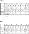
- the sixth block (see eg FIG. 5 ) consists of a line for preferential distribution of the green to phases with more signal groups.
- the phase which includes the pedestrian signals is preferably extended.
- the recognition number for the decision criterion of the number of signal groups is 7.
- the entries of the columns within the blocks for each phase are sorted separately in ascending order. That is, the decision tuples in each phase are resorted, starting with the lowest value and ending with the highest value. Lines that are then only assigned the values 99 are deleted.
- the resorted decision matrix FIG. 3 is in FIG. 4 shown. How to see there is, the decision matrix simplifies significantly, as some of the lines have already been eliminated.
- the order of the blocks themselves determines the sequence and importance, i. the priority, the different types of decision criteria.
- phase durations and signal group durations are adhered to, which are fixed boundary conditions. For example, pedestrians can be given enough time to reach the opposite side of the road. Also, the required clearance times and switching times for the signalized node are maintained here.
- the next priority is the maximum phase durations and signal group durations. Consequently, it is also possible that by observing the minimum conditions, the maximum conditions of individual phases or signal groups can be violated.
- Another priority is the performance and the free green. By observing the minimum and maximum conditions, individual signal groups may not reach their capacity.
- the phases with the highest number of signal groups are preferred.
- the phases with the lowest Phase duration are preferred. This is a decision criterion, especially for multiple applications.
- the above decision criteria are processed sequentially, ie in the order of their priorities. Since the lines in which all decision values were 99 have been deleted, it may happen that some blocks are omitted before the decision-making and are no longer to be considered in this step. Therefore, it may also be that all boundary conditions such as the minimum conditions and maximum conditions of the first four blocks are not used for the decision. This is for example in the in FIG. 4
- the decision matrix shown in the case. Here is the first, relevant block the green time reserve.
- the decision making in the next row proceeds on the basis of these two phases. Analogously, this is done in three or more equivalent phases. If in the next line one of these phases is the one with the lowest value, the decision-making process ends in this phase.
- the second receives the phase that comes first within the phase sequence.
- the method results in a clear candidate selection over a decision path with decreasing priority of the decision criteria.
- the special feature of this procedure is the clear transparency, which is given by the high system of the candidate selection procedure. So you can even read on the basis of the logged matrixes even at a later time, which phase has received on the basis of which decision criterion the respective green time interval.
- a second embodiment is in FIG. 5 shown.
- phase P1 is allocated the second. It should be noted that the phases P3 to P5 have already been excluded in the first row of the decision matrix and all other rows of this matrix had no influence on the further selection procedure. This also applies if a value is smaller than in phase P1 or P2.
- FIG. 6 Another embodiment is in FIG. 6 shown.
- FIG. 6 1 shows a decision matrix in which, in addition to the block for distributing the green time reserves C res of the lane group groups, a priority block with the boundary condition of the maximum signal group duration C max (i, n) is used for decision-making.
- a priority block with the boundary condition of the maximum signal group duration C max (i, n) is used for decision-making.
- the phase 2 from the further decision making.
- phase P1 receives here the additional green time of 1 second, because this with respect to the remaining phase P1, P3, P4 and P5 the smallest value in the line 2 of the decision matrix, the block for the green time reserve C res having.
- this time the decision ends after the second line, because a candidate was found.
- the decision matrix can be replaced by a corresponding decision tree that enables reliable candidate selection based on the same systematic decision criteria as defined for the matrix and a corresponding priority list.
- Such a tree can be particularly advantageous if the decision-making can no longer be linearly described.
- a control unit controls a plurality of sub-nodes, which indeed run in a signal program and are thus switched simultaneously, for example, but which allow parallel phase sequences within the sub-nodes.
Abstract
Description
Die Erfindung betrifft ein Verfahren und ein Lichtsignalanlagen-Steuerungssystem zur Steuerung von Lichtsignalanlagen für den Straßenverkehr an einem oder mehreren signalisierten Knoten in einem Regelbereich. Insbesondere betrifft sie ein Verfahren, bei dem alle Verkehrsteilnehmer, wie der Individualverkehr, der öffentliche und private Nahverkehr, sowie Fußgänger und Radfahrer in Abhängigkeit der Verkehrssituation berücksichtigt werden können, und erlaubt eine Optimierung des Verkehrsflusses an signalisierten Knoten in einem Regelbereich hinsichtlich der Auswahl der relevanten Stellgrößen, wie zum Beispiel der Phasenfolge, der Umlaufzeitwahl, der Grünzeitverteilung und der Versatzzeitberechnung. Das Verfahren kann aber auch für die planerische Optimierung solcher Verfahren auf Basis von vorab ermittelten Verkehrsdaten eingesetzt werden.The invention relates to a method and a traffic signal control system for controlling traffic light systems at one or more signalized nodes in a control area. In particular, it relates to a method in which all road users, such as private transport, public and private transport, as well as pedestrians and cyclists can be taken into account depending on the traffic situation, and allows an optimization of the traffic flow at the signaled nodes in a control area with regard to the selection of the relevant Manipulated variables, such as the phase sequence, the rotation time selection, the green time distribution and the offset time calculation. However, the method can also be used for the planning optimization of such methods on the basis of previously determined traffic data.
Verkehrssteuerungssysteme der komplexeren Art werden heute auf vielbefahrenen Straßen, speziell auf Autobahnen und in stark frequentierten innerörtlichen Strecken wie beispielsweise Ring- und Einfallstraßen von Großstädten, verwendet. Sie weisen üblicherweise eine Vielzahl von Verkehrssteuerungs-Aktuatoren auf. Hierunter werden alle Verkehrsregelungsinstrumente verstanden, die durch Signalgebung an Verkehrsteilnehmer Verkehrsregeln und Verkehrshinweise weitergeben. Insbesondere fallen darunter also Lichtsignalanlagen, Verkehrszeichen, die variabel oder statisch solche Regeln und Hinweise anzeigen, jedoch auch Instrumente wie der Verkehrsfunk oder die Verkehrsregelung über Ferneinfluss auf Navigationssysteme.Traffic control systems of the more complex type are now used on busy roads, especially on highways and in highly frequented inner-city routes such as ring roads and major city streets. They usually have a large number of traffic control actuators. This is understood as meaning all traffic control instruments which pass on traffic rules and traffic information to traffic participants by means of signaling. In particular, this includes traffic light systems, traffic signs that variably or statically display such rules and instructions, but also instruments such as traffic information or traffic control via remote control of navigation systems.
Zwischen der innerörtlichen Anwendung und der außerörtlichen Anwendung ergeben sich hierbei deutliche Unterschiede. Städtische Verkehrssteuerungssysteme stellen vor allem darauf ab, über eine Steuerung von Lichtsignalanlagen durch ein urbanes Verkehrsmanagement-System innerstädtische Verkehrsflüsse effektiv zu steuern bzw. zu leiten. Dagegen weisen außer-örtliche, speziell Autobahnverkehrssteuerungssysteme, üblicherweise eine deutlich größere Anzahl unterschiedlicher Aktuatoren zur Steuerung von Verkehrsflüssen auf. Hierunter zählen unter anderem variable Verkehrsregelungsanzeigen, die Geschwindigkeitsbegrenzungen, Überholverbote, Geschwindigkeitsgebote, Sicherheitswarnungen, Wetterinformationen und andere strecken- bzw. umweltrelevante Anzeigen darstellen können.There are clear differences between the local application and the non-local application. Municipal traffic control systems are mainly on it via an urban traffic management system to effectively control or direct urban traffic flows via a traffic signal system. In contrast, off-site, especially motorway traffic control systems, usually have a significantly larger number of different actuators for controlling traffic flows. These include, but are not limited to, variable traffic control indicators that may represent speed limits, overtaking bans, speed bids, safety alerts, weather information, and other distance or environmental indicators.
Inner- wie außerstädtische Verkehrsleitsysteme weisen außerdem oft Richtungspfeile auf, die bestimmte Fahrstreifen für einen Verkehr sperren bzw. freigeben können oder einen notwendigen Fahrspurwechsel anzeigen. Zusätzlich hierzu können Umleitungen ausgeschildert und Staugefahren angezeigt werden, weshalb sie neben fest installierten Anzeigetafeln auch mobile Anzeigen umfassen können.Inner and extra urban traffic control systems also often have directional arrows that can lock or unlock certain lanes for traffic or indicate a necessary lane change. In addition to this, diversions can be signposted and congestion can be seen, which can include mobile displays in addition to permanently installed scoreboards.
Verfahren für die Steuerung von Lichtsignalanlagen für den Straßenverkehr in Abhängigkeit vom Verkehrsaufkommen sind bekannt und gewinnen zunehmend an Bedeutung. Dabei wird häufig die Grünzeit bemessen, d.h. eine bedarfsgerechte Anpassung der Freigabezeit (= Grünzeit) ermittelt. Dabei wird zur verkehrsabhängigen Freigabezeitanpassung bisher vorwiegend mit Zeitlücken zwischen den Fahrzeugen und Belegungsgraden in den Zufahrten zu den Knotenpunkten gearbeitet, wobei häufig feste Schwellenwerte definiert werden. Das Über- bzw. Unterschreiten dieser Schwellenwerte, oder auch Kombinationen dieser Eingangsgrößen, führen zum Abschalten oder Verlängern des laufenden Verkehrsstroms. Bei der Freigabezeitanpassung mittels Zeitlückenmessung werden über einen Detektor in der Knotenpunktzufahrt die zeitlichen Abstände aufeinanderfolgender Fahrzeuge eines Fahrzeugstroms als Zeitlücke gemessen. Die Freigabezeit wird nach Ablauf der gewählten minimalen Freigabezeit oder nach Erreichen eines frühesten Zeitpunktes im Umlauf dem aktuellen Bedarf der zufließenden Fahrzeuge angepasst. Die Freigabezeit kann so lange verlängert werden, bis die gemessene Zeitlücke mindestens so groß ist wie ein vorgegebener Zeitlückenschwellenwert oder bis die längste festgelegte Freigabezeit oder der späteste Verlängerungszeitpunkt im Signalumlauf erreicht wird.Methods for the control of traffic light systems as a function of the traffic volume are known and are becoming increasingly important. In this case, the green time is often measured, ie a needs-based adjustment of the release time (= green time) determined. In this case, traffic-dependent release time adaptation has hitherto mainly dealt with time gaps between the vehicles and occupancy levels in the access roads to the junctions, with fixed threshold values frequently being defined. Exceeding or undershooting these threshold values, or even combinations of these input variables, leads to switching off or extending the current traffic flow. In the release time adjustment by means of time gap measurement, the time intervals between successive vehicles of a vehicle current are measured as a time gap via a detector in the node approach. The release time is adjusted to the current needs of the incoming vehicles after the selected minimum release time or after reaching an earliest time in circulation. The release time may be extended until the measured time gap is at least as large as a predetermined timeout threshold or until the longest committed release time or time limit is reached in the recirculating signal.
Bei der Freigabezeitanpassung mittels Belegungsgradmessung werden ebenfalls Schwellenwerte für den Abbruch der Freigabezeit definiert. Die Auswertung der Messwerte erfolgt getrennt für jeden Fahrstreifen. Der Originalbelegungsgrad wird mit Hilfe eines Ausgleichsverfahrens geglättet. Gegebenenfalls wird je ein Ausgleichsfaktor für ansteigende und abfallende Tendenzen der Originalwerte verwendet.With the release time adjustment via occupancy rate measurement, threshold values for canceling the release time are also defined. The evaluation of the measured values is done separately for each lane. The original occupancy rate is smoothed using a compensation procedure. If necessary, a compensation factor for rising and falling tendencies of the original values is used.
Bei der so genannten "Volume-Density-Method" wird die Anzahl der vor Rot stehenden Fahrzeuge mit den Zeitlücken im laufenden Verkehr verglichen. Dabei wird eine Grenzwertkurve definiert, die einer festen Anzahl wartender Fahrzeuge einen Festzeitlückenwert zuweist, bis zu dem die laufende Freigabezeit noch verlängert wird. In einer erweiterten Methode kann die Grünzeitbemessung nach Dringlichkeit erfolgen. Die Anzahl der vor Rot stehenden Fahrzeuge wird hier mit den Zeitlücken und zusätzlich mit der Belegung im laufenden Verkehr verglichen. Auch hier werden Schwellenwerte verwendet.In the so-called "Volume Density Method", the number of vehicles standing in front of red is compared with the time gaps in current traffic. A limit curve is defined, which assigns a fixed time gap value to a fixed number of waiting vehicles, up to which the current release time is still extended. In an advanced method, the green-time calculation can be done on an urgency basis. The number of vehicles standing in front of red is compared here with the time gaps and additionally with the occupancy in current traffic. Again, thresholds are used.
In der
Ein einfaches Beispiel eines modellbasierten Verfahrens ist ein Grünzeitbemessungsverfahren, bei dem der Auslastungsgrad einer laufenden Signalgruppe mit dem Auslastungsgrad einer feindlichen, auf Rot stehenden Signalgruppe verglichen wird.A simple example of a model-based method is a green time estimation method in which the utilization level of a current signal group is compared with the utilization level of an enemy red signal group.
Jedoch haben alle diese Verfahren ihre Grenzen, insbesondere hinsichtlich der algorithmischen Ansätze auf Grund fehlender oder zu einfacher Steuerungsmodelle. Weitere Grenzen ergeben sich aus einer starken Einschränkung von verkehrlich relevanten Steuerungsszenarien, z.B. dass eine Signalgruppe wenn sie in mehreren Phasen hintereinander auftritt nur in der letzten Phase verlängert werden kann, nicht aber in der ersten Phase, worunter ggf. andere Signalgruppen die als zweit wichtigste zusätzliches Grün benötigen würden dieses nicht bekommen.However, all of these methods have their limitations, especially in terms of algorithmic approaches due to missing or too simple control models. Further limits result from a strong restriction of traffic relevant control scenarios, eg that a signal group, if it occurs in several phases one behind the other, can only be extended in the last phase, but not in the first phase, among which possibly other signal groups would need the second most important additional green do not get this.
Neuere Ansätze optimieren die Grünzeitverteilung, Umlaufzeitwahl und Versatzzeitoptimierung sowie ggf. die Auswahl der Phasenfolge in einem geschlossenen Steuerungsmodell gleichzeitig beziehungsweise parallel. Nachteilig hiervon ist, dass das Optimierungsproblem NP vollständig ist, d.h. mit bekannten nicht heuristischen Optimierungsverfahren das Systemoptimum nicht in endlicher Zeit gefunden werden kann. Daher muss auf heuristische Optimierungsverfahren zurückgegriffen werden, wie zum Beispiel "Simulated Anealing" oder Tabusuche oder genetische Algorithmen wie von Braun in "Ein echtzeitfähiger Evolutionärer Algorithmus zur netzweiten Optimierung der Lichtsignalsteuerung" beschrieben.More recent approaches optimize the green time distribution, round-trip time selection and offset time optimization as well as possibly the selection of the phase sequence in a closed control model simultaneously or in parallel. The disadvantage of this is that the optimization problem NP is complete, i. with known non-heuristic optimization methods, the system optimum can not be found in finite time. Therefore, it is necessary to resort to heuristic optimization methods, such as "Simulated Anealing" or taboo search or genetic algorithms as described by Braun in "A Real-Time Evolutionary Algorithm for Network-Wide Optimization of Traffic Light Control".
Jedoch haben auch diese Verfahren ihre Grenzen, insbesondere hinsichtlich der benötigten Rechenzeit sowie der Anzahl der zu berücksichtigten Stellgrößen, und ebenso algorithmische Grenzen auf Grund der Komplexität der Verfahren und dem Umstand, dass das Finden des Systemoptimums nicht garantiert werden kann. So werden in den vorstehend aufgeführten Verfahren die jeweiligen Stellgrößen, wie die Phasenfolge, die Umlaufzeitwahl, die Grünzeitverteilung und die Versatzzeitberechung, gemeinsam oder getrennt voneinander optimiert.However, these methods also have their limitations, in particular with regard to the required computing time and the number of manipulated variables to be taken into account, as well as algorithmic limits due to the complexity of the methods and the fact that finding the system optimum can not be guaranteed. Thus, in the methods listed above, the respective manipulated variables, such as the phase sequence, the round trip time selection, the green time distribution and the offset time calculation, are optimized jointly or separately from one another.
Im Gegensatz zur parallelen beziehungsweise gleichzeitigen Optimierung in einem Optimierungsverfahren besteht der Vorteil einer getrennten Optimierung in eigenständigen zeitlich in der Regel hintereinander ausgeführten Optimierungsverfahren darin, dass die Optimierungskomplexität der einzelnen Optimierungen so reduziert wird, dass sie nicht mehr NP-vollständig sind und dass das Systemoptimum der jeweiligen Einzelaufgabe nicht in endlicher Zeit gefunden werden kann.In contrast to the parallel or simultaneous optimization in an optimization method, the advantage of a separate optimization in independent optimization processes, which are generally consecutive in time, is that the optimization complexity of the individual optimizations is reduced to such an extent that they are no longer NP-complete and the system optimum of the optimization respective individual task can not be found in finite time.
Ein Beispiel für ein solches, aus Einzeloptimierungen bestehendes Verfahren, das zur Grünzeitoptimierung ein Gradientenabstiegsverfahren verwendet, ist das von Siemens entwickelte Verfahren, das auch unter dem Namen "Motion 4.x" bekannt ist. Da jedoch in der Grünzeitverteilung mehrere Stellgrößen, nämlich die Grünzeitanteile der Phasen, optimiert werden ergibt sich immer noch ein mehrdimensionaler Lösungsraum. Die Lösung muss daher in mehreren Verfahrensschritten mittels Iterationen optimiert werden. Dies führt generell zu einer langen Rechenzeit. Zudem ist das Verfahren wenig transparent (so genannter Blackboxcharakter) und Randbedingungen können in Form zusätzlicher Zielfunktionsterme nur bedingt berücksichtigt werden.An example of such a process consisting of individual optimizations which uses a gradient descent method for green time optimization is the method developed by Siemens, which is also known under the name "Motion 4.x". However, since several manipulated variables, namely the green-time components of the phases, are optimized in the green-time distribution, there is still a multidimensional solution space. The solution must therefore be optimized in several process steps by means of iterations. This generally leads to a long computing time. In addition, the process is not very transparent (so-called black box character) and boundary conditions can be considered only to a limited extent in the form of additional target function terms.
Neben diesem Verfahren sind modellbasierte Verfahren zur Grünzeitoptimierung bekannt, die die Grünzeitverteilung in Zeiteinheiten durchführen, z.B. sekundenweise. Dadurch reduziert sich die Komplexität der Optimierung auf nur eine Dimension, nämlich die der zu verteilenden Grünzeit. Diese lassen sich wiederum in Verfahren einteilen, die zur Findung einer Lösung mehrere Iterationen benötigen, um sich der optimalen Lösung unter Berücksichtigung von Randbedingungen anzunähern, und in Verfahren, die die optimale Grünzeitverteilung in einer Iteration erreichen. Eine Iteration bedeutet dabei, dass jede zu verteilende Zeiteinheit einmal verteilt worden ist. Eine Iteration besteht also aus einer Anzahl von Unteriterationen entsprechend der Anzahl der zu verteilenden Zeiteinheiten.Besides this method, model-based methods for green time optimization are known which perform the green time distribution in units of time, e.g. second increments. This reduces the complexity of the optimization to only one dimension, namely the green time to be distributed. These can in turn be divided into methods that require a number of iterations to find a solution in order to approximate the optimal solution taking into account boundary conditions, and methods that achieve the optimal green time distribution in an iteration. An iteration here means that each time unit to be distributed has been distributed once. An iteration therefore consists of a number of sub-iterations corresponding to the number of time units to be distributed.
Beispiele für Verfahren mit mehreren Iterationen sind das so genannte Sperrgruppenverfahren, in dem feindliche Signalgruppen gesucht werden, sowie das Verfahren nach dem Handbuch für die Bemessung von Straßenverkehrslagen (HBS). Diese Verfahren mit mehreren Iterationen benötigen jedoch erheblichen und vorab nicht bestimmbaren Rechenzeitbedarf, sind ebenfalls wenig transparent (Blackboxcharakter), Randbedingungen können meist nur implizit berücksichtigt werden, und die Verfahren unterliegen oft auch algorithmischen Einschränkungen, z.B. bezüglich der unterstützten Signalkonfigurationen.Examples of methods with multiple iterations are the so-called lock group method, in which enemy signal groups are searched, and the method according to the Manual for the design of road traffic situations (HBS). However, these methods with multiple iterations require considerable and previously unidentifiable computing time, are also not very transparent (black box character), boundary conditions can usually only be considered implicitly, and the procedures Often also subject to algorithmic restrictions, eg with regard to the supported signal configurations.
Verfahren zur Grünzeitverteilung mit nur einer Iteration zur Grünzeitverteilung sind zum Beispiel die Verfahren "Motion 2.x" und "Motion 3.x". Diese benötigen auf Grund der einfachen Berechnungsweise eine niedrigere Rechenzeit und Randbedingungen können einfacher eingehalten werden, besitzen aber auch Nachteile. Insbesondere können sie nicht alle Signalkonstellationen, wie z.B. Signalüberlappungen einschließlich einer inneren Mehrphasigkeit, optimal berücksichtigen, und die Einhaltung der Regeln ist nicht transparent, d.h. auch dieses Verfahren hat einen Blackboxcharakter. Eine innere Mehrphasigkeit ist gegeben, wenn zwei Signalgruppen gemeinsam freigegeben werden und zudem die eine der beiden Signalgruppen im Vorlauf und die andere der beiden Signalgruppen im Nachlauf freigegeben wird.Procedures for green time distribution with only one iteration for green time distribution are, for example, the "Motion 2.x" and "Motion 3.x" methods. Due to the simple calculation method, these require a lower computing time and boundary conditions can be met more easily, but they also have disadvantages. In particular, they can not handle all signal constellations, e.g. Signal overlaps including an inner multi-phase, optimally take into account, and compliance with the rules is not transparent, i. This procedure also has a black box character. An inner multi-phase is given when two signal groups are released together and also one of the two signal groups in the flow and the other of the two signal groups is enabled in the wake.
Neben den vorstehend beschriebenen Verfahren zur Grünzeitverteilung in solchen Verkehrssteuerungssystemen beeinflusst die Umlaufzeitwahl in den signalisierten Knoten und dem gesamten Regelbereich die Leistungsfähigkeit der signalisierten Knoten. So ist grundsätzlich eine Änderung der Umlaufzeit mit Umschaltverlusten verbunden, wenn die Verkehrssteuerungssysteme eine gemischt zentrale und dezentrale Architektur haben. Dies liegt daran, dass in den Steuergeräten dieser Systeme zwischen unterschiedlichen Signalplänen umgeschaltet werden muss. Die Umschaltverluste ergeben sich dadurch, dass die signalisierten Knoten synchronisiert werden müssen. Auf Grund der Synchronisation ändern sie jedoch ihre Wellenlage. Dies führt in der Regel zu zusätzlichen Halten von Verkehrsteilnehmern während der Umschaltung.In addition to the above-described methods for green time distribution in such traffic control systems, the round trip time selection in the signaled nodes and the entire control range affects the performance of the signaled nodes. Thus, in principle, a change in the cycle time is associated with switching losses, if the traffic control systems have a mixed centralized and decentralized architecture. This is due to the fact that in the control units of these systems must be switched between different signal plans. The switching losses result from the fact that the signaled nodes must be synchronized. However, due to the synchronization, they change their wave position. This usually leads to additional holding of road users during the switchover.
So sind zur Ermittlung der Umlaufzeit verschiedene Verfahren bekannt, die hier zum Verständnis kurz erläutert werden sollen.Thus, various methods are known for determining the circulation time, which will be briefly explained here for understanding.
In einem beispielhaften Verfahren kann die Umlaufzeit mittels einer Bewertung von Wartezeiten und Halten im koordinierten Gesamtsystem entsprechend einer ganzheitlichen Optimierung ermittelt werden. Der Nachteil hiervon ist, dass die Wahl der Umlaufzeit wenig nachvollziehbar und auf Grund der Abhängigkeit von der Koordinierung Schwankungen unterworfen ist.In an exemplary method, the round trip time can be determined by means of an evaluation of waiting times and holding in the coordinated overall system in accordance with a holistic optimization. The disadvantage of this is that the choice of the orbital period is less comprehensible and subject to fluctuations due to the dependence on the coordination.
In einem weiteren Verfahren beruht die Umlaufzeitwahl auf der kritischen Signalgruppe, also der Signalgruppe in einem Regelbereich, die den höchsten Ausnutzungsgrad besitzt. Die Umlaufzeitwahl ist dadurch interpretierbar, aber immer noch starken Schwankungen unterworfen. Dies liegt zum einen daran, dass die Verkehrsnachfrage an den Signalgruppen starke Schwankungen besitzen kann, und zum anderen daran, dass sich die am stärksten ausgelastete Signalgruppe in dem Regelbereich schnell ändern kann. Dieses Verfahren wird zum Beispiel in "Motion 4.x" verwendet.In another method, the round trip time selection based on the critical signal group, ie the signal group in a control range, which has the highest utilization. The orbital time selection is thus interpretable, but still subject to strong fluctuations. This is partly due to the fact that the traffic demand on the signal groups can vary greatly, and secondly because the most heavily used signal group in the control area can change rapidly. This method is used for example in "Motion 4.x".
Es ist daher eine Aufgabe der vorliegenden Erfindung, eine verbesserte Alternative zu den bisherigen Verkehrssteuerungsverfahren sowie ein Lichtsignalanlagen-Steuerungssystem hierfür zu schaffen.It is therefore an object of the present invention to provide an improved alternative to the previous traffic control methods and a traffic signal control system therefor.
Diese Aufgabe wird zum einen durch ein Steuerungsverfahren nach Anspruch 1 und zum anderen durch ein Lichtsignalanlagen-Steuerungssystem nach Anspruch 14 gelöst.This object is achieved on the one hand by a control method according to
Bei dem erfindungsgemäßen Verfahren zur Steuerung von Lichtsignalanlagen für den Straßenverkehr an einem oder mehreren signalisierten Knoten in einem Regelbereich erfolgt die Verteilung von Grünzeiten auf die jeweiligen Signalgruppen der einzelnen signalisierten Knoten mittels eines Kandidatenauswahlverfahrens gemäß einer Anzahl von vorgegebenen Entscheidungskriterien, vorzugsweise mehreren verschiedenen Entscheidungskriterien.In the method according to the invention for controlling traffic light systems at one or more signalized nodes in a control area, the distribution of green times to the respective signal groups of the individual signalized nodes is carried out by means of a candidate selection method according to a number of predetermined decision criteria, preferably several different decision criteria.
Das erfindungsgemäße Verfahren kann hierfür auf einer allgemeinen Methode zur Grünzeitverteilung aufbauen, in der eine gemeinsame Umlaufzeit eines Regelbereiches, die so genannte Regelbereichs-Umlaufzeit, bei der Grünzeitverteilung eines jeden signalisierten Knotens als Basis genommen wird. Der grundsätzliche Ablauf dieser allgemeinen Methode besteht aus den folgenden drei Schritten:
- 1. Berechnung der minimalen Umlaufzeit je Knoten bezüglich Randbedingungen und Auslastung für alle Knoten des Regelbereichs;
- 2.Auswahl der gemeinsamen Umlaufzeit des Regelbereichs;
- 3. Grünzeitverteilung für alle signalisierten Knoten für die gewählte Umlaufzeit des Regelbereichs gemäß dem vorstehend erläuterten Verfahren mit einer Iteration.
- 1. Calculation of the minimum round trip per node in terms of boundary conditions and utilization for all nodes of the control area;
- 2.selection of the common cycle time of the control area;
- 3. Green time distribution for all signalized nodes for the selected round trip time of the control range according to the method explained above with an iteration.
Ein Vorteil dieser allgemeinen Methode ist, dass die Umlaufzeit von den Auslastungsgraden aller Signalgruppen eines signalisierten Knotens abhängt. Damit erfolgt eine räumliche Mittelung.An advantage of this general method is that the round trip time depends on the utilization levels of all signal groups of a signaled node. This is a spatial averaging.
Ein Knoten ist erfindungsgemäß als ein Bereich im Straßenverkehr definiert, an dem sich feindliche Verkehrsströme treffen, insbesondere kreuzen oder einmünden. Beispiele solcher Knoten sind Kreuzungen, Fußgängerüberwege, Einmündungen etc. Man spricht von einem signalisierten Knoten, wenn ein oder mehrere Verkehrsströme an diesem Knoten durch eine Signalanlage, insbesondere eine Lichtsignalanlage, gesteuert werden. Hierbei ist der Begriff Lichtsignal nicht nur auf Lichtzeichen beschränkt, sondern es ist auch möglich, dass die Lichtzeichen durch weitere Signale wie zum Beispiel akustische Signale ergänzt werden. Deshalb werden diese nachstehend auch als Signalgeber benannt. Gerade im Bereich der Fußgängersignale werden häufig akustische und optische Signale in Kombination eingesetzt, um zum Beispiel sehbehinderten Personen die Benutzung zu erleichtern bzw. um durch eine doppelte Signalisierung eine erhöhte Aufmerksamkeit bei den Verkehrsteilnehmern zu erzielen.According to the invention, a node is defined as an area in traffic on which hostile traffic flows meet, in particular intersect or terminate. Examples of such nodes are intersections, pedestrian crossings, junctions, etc. One speaks of a signalized node when one or more traffic streams are controlled at this node by a signaling system, in particular a traffic signal system. Here, the term light signal is not limited to light signals, but it is also possible that the light signals are supplemented by other signals such as acoustic signals. Therefore, these are also named as signalers below. Especially in the field of pedestrian signals acoustic and optical signals are often used in combination, for example, to facilitate the use of visually impaired people or to achieve by a double signaling increased attention among road users.
Ein Regelbereich umfasst gewöhnlich mehr als einen signalisierten Knoten und dient dazu, die Verkehrsströme an zwei oder mehreren im Verkehrsstrom hintereinander liegenden Knoten zu steuern. Insbesondere dienen die Regelbereiche dazu, den Verkehrsfluss in diesem zu erhöhen. Häufig wird dann auch von einer "Grüne-Welle-Schaltung" gesprochen, die grundsätzlich einen optimalen Fall einer Verkehrssteuerung darstellt. Eine einfache Ausführungsform einer solchen Verkehrssteuerung wählt die vorab festgelegten Signalprogramme und damit auch die Umlaufzeit in einem Regelbereich tageszeitabhängig, da die Verkehrsströme für gewöhnlich stark mit der Tageszeit variieren. Zum Beispiel kommt es morgens häufig zu einem starken Verkehrsaufkommen in Richtung Stadtmitte, während sich die Verkehrsströme gegen Abend in die entgegengesetzte Richtung, das heißt stadtauswärts, umkehren. Ein Regelbereich kann dabei eine ganze Stadt, einen Teil einer Stadt oder aber auch nur Hauptverkehrsadern oder deren Teile umfassen.A control area usually comprises more than one signaled node and serves to control the traffic streams at two or more nodes consecutive in the traffic flow. In particular, the control areas serve to increase the traffic flow in this. Often, a "green-wave circuit" is then spoken of, which basically represents an optimal case of traffic control. A simple embodiment of such a traffic control selects the pre-defined signal programs and thus also the cycle time in a control area daytime-dependent, since the traffic flows usually vary greatly with the time of day. For example, there is often a heavy traffic in the morning in the direction of the city center, while in the evening the traffic flows in the opposite direction, ie out of town. A control area can include an entire city, a part of a city or just main traffic arteries or their parts.
Um eine Verbesserung bzw. Optimierung des Verkehrsflusses in einem Regelbereich zu erzielen, wird in dem erfindungsgemäßen Verfahren anstelle der tageszeitabhängigen Auswahl von Signalprogrammen eine verkehrsabhängige Verteilung der Grünzeiten auf die jeweiligen Fahrstreifengruppen beziehungsweise Signalgruppen der einzelnen signalisierten Knoten angestrebt. Dabei wird bei der Verteilung der Grünzeiten, die nachstehend detaillierter erläutert wird, eine Methode eingesetzt, die auf variable Verkehrsströme relativ schnell reagieren kann. Als eine Signalgruppe wird erfindungsgemäß eine Gruppe von Lichtsignalen, die jeweils identische Signalisierungen besitzen verstanden. Zum Beispiel werden bei mehrstreifigen Fahrbahnen neben seitlich angebrachten Signalgebern oft auch Signalgeber über den Fahrbahnen angebracht, wobei jeweils ein Signalgeber über der Fahrbahn mit einem seitlichen Signalgeber eine Signalgruppe darstellen. Verallgemeinert spricht man immer von Signalgruppen, auch wenn es nur einen Signalgeber gibt. Fahrstreifengruppen sind Gruppen von Fahrstreifen, die eine homogene Signalisierung besitzen, das heißt jeder Fahrstreifen wird von denselben Signalgruppen gesteuert. Nichtsignalsierte Fahrstreifen einer Knotenzufahrt werden auch zu Fahrstreifengruppen zusammengefasst, denen kein Signal zugeordnet ist. Signalgruppen können als Hauptsignalgruppen auch mehreren Fahrstreifengruppen zugeordnet sein. Neben einer Hauptsignalgruppe kann einer Fahrstreifengruppe auch ein Zusatzsignal zugeordnet sein, so dass sich die Fahrstreifengruppen dann zwar nicht durch die Hauptsignalgruppe aber durch die Zusatzsignalgruppe unterscheiden. Beispielhaft kann eine Knotenzufahrt drei Fahrstreifen besitzen, von denen zwei geradeaus und einer nach rechts geführt wird. Den beiden Fahrstreifen geradeaus ist ein dreifeldiges Hauptsignal mit Vollscheiben zu geordnet, dem Rechtsabbiegefahrstreifen dasselbe dreifeldige Hauptsignal und zusätzlich ein zweifeldiges Zusatzsignal mit Rechtsabbiegepfeilen. Daraus ergeben sich zwei Fahrstreifengruppen. Die Erste bestehend aus zwei Fahrstreifen gerade aus, denen nur das Hauptsignal zugeordnet ist. Die Zweite bestehend aus dem Fahrstreifen nach rechts, dem das Hauptsignal und das Zusatzsignal zugeordnet ist. Die Fahrstreifengruppen sind in der deutschsprachigen Literatur nicht explizit definiert, wohl aber im "Highway Capacity Manual", das unter anderem die Lichtsignalplanung und Versorgung in den USA definiert.In order to achieve an improvement or optimization of the traffic flow in a control range, a traffic-dependent distribution of the green times to the respective lane groups or signal groups of the individual signalized nodes is sought in the inventive method instead of the daytime-dependent selection of signal programs. Here, the distribution of green times, which will be explained in more detail below, a method is used, which can respond to variable traffic flows relatively quickly. As a signal group is understood according to the invention a group of light signals, each having identical signaling. For example, in multi-lane roadways next to side-mounted signalers often signalers are mounted on the lanes, each representing a signal generator on the road with a side signal generator a signal group. Generally speaking, one always speaks of signal groups, even if there is only one signal generator. Lane groups are groups of lanes that have homogeneous signaling, that is each lane is controlled by the same signal groups. Not signal Disseminated Lanes of a node access are also combined to lane groups to which no signal is assigned. Signal groups can also be assigned as main signal groups to several lane groups. In addition to a main signal group, a lane group can also be assigned an additional signal, so that the lane groups then do not differ in the main signal group but in the additional signal group. By way of example, a node access may have three lanes, two of which are straight ahead and one right. The two lanes straight ahead is a dreifeldiges main signal with full discs to be sorted, the Rechtsabbiegefahrstreifen the same dreifeldige main signal and in addition a zweeldiges additional signal with Rechtsabbiegepfeilen. This results in two lane groups. The first consisting of two lanes straight from which only the main signal is assigned. The second consisting of the lane to the right, to which the main signal and the additional signal is assigned. The lane groups are not explicitly defined in the German-language literature, but they are defined in the "Highway Capacity Manual", which among other things defines traffic signal planning and care in the USA.
Die Grünzeitverteilung erfolgt durch ein spezielles Kandidatenauswahlverfahren, in dem ein Kandidat, zum Beispiel eine spezielle Phase eines signalisierten Knotens oder eine spezielle Signalgruppe, für das jeweilige zu vergebende Grünzeitintervall anhand von vorgegebenen Entscheidungskriterien auf einfache und insbesondere nachvollziehbare Weise gezielt ausgewählt wird. Eine Phase im Sinne der Erfindung ist ein bestimmter Signalisierungszustand eines bestimmten Knotens, welcher durch freigegebene Signalgruppen definiert ist. Erfindungsgemäß erfolgt die Auswahl für jedes Entscheidungskriterium mit Hilfe eines Ausschlussverfahrens, bei dem immer mehr Kandidaten auf Grund ihres vorab ermittelten Entscheidungswertes durch ein vorgegebenes Raster herausfallen. Sollte beim Durchlaufen des Verfahrens für ein Entscheidungskriterium keine eindeutige Auswahl möglich sein, wird das Verfahren für ein weiteres Entscheidungskriterium anhand der verbliebenen Kandidaten fortgesetzt, bis lediglich nur noch ein Kandidat für das zu verteilende Grünzeitintervall übrigbleibt. Diesem wird dann die Grünzeit zugeordnet und das Verfahren beginnt von vorne für das nächste zu verteilende Grünzeitintervall.The green time distribution is performed by a specific candidate selection method in which a candidate, for example a specific phase of a signaled node or a special signal group, is specifically selected for the respective green time interval to be awarded on the basis of predetermined decision criteria in a simple and, in particular, comprehensible manner. A phase in the sense of the invention is a specific signaling state of a specific node, which is defined by released signal groups. According to the invention, the selection is made for each decision criterion with the aid of an exclusion method, in which more and more candidates fall out due to their previously determined decision value by a predetermined grid. If no clear selection is possible when going through the procedure for a decision criterion, the procedure becomes for a further decision criterion on the basis of the remaining candidates continued until only one candidate for the green time interval to be distributed remains. This is then assigned the green time and the process starts again from the beginning for the next green time interval to be distributed.
Durch die Auswahl eines einzigen Kandidaten in dem erfindungsgemäß verwendeten Kandidatenauswahlverfahren mittels der vorstehend erläuterten, gezielten Auswahl anhand von einem oder mehreren Entscheidungskriterien kann unter anderem eine Verbesserung des zu steuernden Verkehrsflusses, d.h. eine Verbesserung der verkehrlichen Qualität an den Knoten, erzielt werden. Außerdem hat dieses Kandidatenauswahlverfahren eine hohe Transparenz und Nachvollziehbarkeit gegenüber den bisherigen Verfahren. Insbesondere die gezielte Auswahl eines einzigen verbleibenden Kandidaten anhand von einem oder mehreren Entscheidungskriterien erhöht die Transparenz und Nachvollziehbarkeit der Steuerung im Vergleich zu den bisher eingesetzten Verfahren, die meist auf Basis von komplexen Entscheidungsbäumen die Grünzeitverteilung regelten. Häufig war jedoch auf Grund einer fehlenden Systematik bisher keine eindeutige Auswahl eines einzigen Kandidaten möglich.By selecting a single candidate in the candidate selection method used according to the invention by means of the above-explained targeted selection on the basis of one or more decision criteria, an improvement of the traffic flow to be controlled, i. an improvement of the traffic quality at the nodes, can be achieved. In addition, this candidate selection process has a high degree of transparency and traceability compared to the previous methods. In particular, the targeted selection of a single remaining candidate based on one or more decision criteria increases the transparency and traceability of the control in comparison to the previously used procedures, which usually regulated the green-time distribution on the basis of complex decision trees. Often, however, due to a lack of systematics, no clear selection of a single candidate was possible.
Ein erfindungsgemäßes Lichtsignalanlagen-Steuerungssystem für die Verkehrssteuerung an einem oder mehreren signalisierten Knoten in einem Regelbereich weist dementsprechend zumindest folgende Komponenten auf:
- eine Datenübermittlungsschnittstelle zur Übernahme von Verkehrsdaten aus einer Verkehrsüberwachungseinrichtung,
- eine Verkehrsdaten-Verarbeitungseinheit zur Ermittlung von Lichtsignalanlagen-Steuerungsdaten,
- eine Datenübergabeschnittstelle für die Lichtsignalanlagen-Steuerungsdaten an eine Lichtsignalanlagen-Steuerungseinheit. Die Verkehrsdaten-Verarbeitungseinheit ist dabei so ausgebildet, dass eine Verteilung von Grünzeiten auf Signalgruppen von einzelnen signalisierten Knoten unter Verwendung eines Kandidatenauswahlverfahrens gemäß vorgegebenen Entscheidungskriterien erfolgt.
- a data transmission interface for transferring traffic data from a traffic monitoring device,
- a traffic data processing unit for detecting traffic signal control data,
- a data transfer interface for the traffic signal control data to a traffic signal control unit. The traffic data processing unit is designed so that a distribution of green times on signal groups of individual signalized node below Use of a candidate selection process according to predetermined decision criteria takes place.
In einem derartigen Lichtsignalanlagen-Steuerungssystem können die Datenübermittlungsschnittstelle, die Verkehrsdaten-Verarbeitungseinheit und die Datenübergabeschnittstelle sowohl als allein stehende Einzelkomponenten hardware- und/oder softwaretechnisch ausgeführt als auch gemeinsam innerhalb eines elektrotechnischen Prozessorbausteins integriert sein. Sie können ganz oder teilweise auf einem Rechner eines Verkehrssteuerungssystems realisiert sein. Außerdem können die Datenübernahme- bzw. die Datenübergabeschnittstelle sowohl als Hardware in Form von Eingangs- bzw. Ausgangsbuchsen bzw. drahtlosen Schnittstellen eines Gerätes ausgebildet sein als auch in Form von Software bzw. als Kombination von Hard- und Software-Komponenten. Schnittstellen können beispielsweise in Form von reinen Software-Schnittstellen auch direkt Daten von einem Steuerungssystem übernehmen, wenn beispielsweise die Lichtsignal-Steuerungseinrichtung auf dem gleichen Rechner wie das Steuerungssystem angeordnet ist. Die Schnittstellen können weiterhin kombiniert gemeinsam als Input-/Output-Schnittstelle ausgebildet sein.In such a traffic signal control system, the data transmission interface, the traffic data processing unit and the data transfer interface both as a standalone hardware and / or software components executed as well as be integrated together within an electro-technical processor module. They may be implemented in whole or in part on a computer of a traffic control system. In addition, the Datenübernahme- or the data transfer interface can be designed both as hardware in the form of input and output sockets or wireless interfaces of a device as well as in the form of software or as a combination of hardware and software components. Interfaces, for example, in the form of pure software interfaces and directly take over data from a control system, for example, if the light signal control device is arranged on the same computer as the control system. The interfaces can continue to be combined as an input / output interface.
Der Aufbau des Lichtsignalanlagen-Steuerungssystems in Form von Software hat den Vorteil einer schnellen und kostengünstigen Realisierung. Daher wird zur Durchführung des erfindungsgemäßen Verfahrens bevorzugt ein Computerprogrammprodukt verwendet, welches direkt in einen Prozessor der Rechnereinrichtung ladbar ist und Programmcode-Mittel aufweist, um alle Schritte des vorstehend beschriebenen erfindungsgemäßen Verfahrens auszuführen.The structure of the traffic signal control system in the form of software has the advantage of a quick and cost-effective implementation. For carrying out the method according to the invention, therefore, a computer program product which can be loaded directly into a processor of the computer device and has program code means in order to carry out all the steps of the inventive method described above is preferably used.
Eine solche Softwarekomponente kann nicht nur in einer zentralen Steuerungszentrale implementiert werden. Sondern sie kann zum Beispiel auch in einem dezentralen Dirigenten, d.h. einem Steuergerät, das mehrere benachbarte Knoten übergeordnet steuert, z.B. als Mastersteuergerät, vorhanden sein, insbesondere falls keine Steuerungszentrale vorhanden ist. Daneben ist auch die lokale Verwendung im Steuergerät möglich, wenn die Umlaufzeit des Regelbereichen von außen vorgegeben wird, oder wenn das Steuergerät in beliebigen Umlaufzeiten laufen darf.Such a software component can not be implemented only in a central control center. Instead, it can also be present, for example, in a decentralized conductor, ie a control unit which controls a plurality of adjacent nodes at a higher level, for example as a master control unit, in particular if no control center is present. In addition, the local use in the control unit is possible if the circulation time of the control areas is specified from the outside, or if the control unit may run in any round trip.
Weitere besonders vorteilhafte Ausgestaltungen und Weiterbildungen des erfindungsgemäßen Verfahrens ergeben sich auch aus den abhängigen Ansprüchen sowie der nachfolgenden Beschreibung. Dabei können das erfindungsgemäße Lichtsignalanlagen-Steuerungssystem oder das Computerprogrammprodukt auch entsprechend den abhängigen Ansprüchen zum Verfahren ausgebildet sein.Further particularly advantageous embodiments and developments of the method according to the invention will become apparent from the dependent claims and the following description. In this case, the traffic signal system control system according to the invention or the computer program product can also be designed according to the dependent claims for the method.
Das gesamte zu verteilende Grünzeitintervall kann grundsätzlich komplett an eine Signalgruppe vergeben werden. In einer bevorzugten Ausführungsform des erfindungsgemäßen Verfahrens erfolgt aber die Verteilung der Grünzeiten in vorgegebenen Zeitabschnitten, insbesondere bevorzugt sekundenweise, so dass zweckmäßige Grünzeit- bzw. Freigabeintervalle erhalten werden. Eine sekundenweise Grünzeitverteilung ist hinsichtlich des Rechenbedarfs und der Integration in bestehende Systeme vorteilhaft.The entire green time interval to be distributed can basically be assigned completely to a signal group. In a preferred embodiment of the method according to the invention, however, the distribution of green times in predetermined periods of time, particularly preferably in seconds, so that appropriate green-time or release intervals are obtained. A second green-time distribution is advantageous in terms of computational requirements and integration into existing systems.
Das erfindungsgemäße Verfahren ermöglicht den Einsatz von mehreren Entscheidungskriterien, die bei der Kandidatenauswahl berücksichtigt werden können. Dabei ist es vorteilhaft, den einzelnen Entscheidungskriterien Prioritäten zuzuordnen, um dann in dem Verfahren zur Verteilung der Grünzeiten die Entscheidungskriterien gemäß den ihnen zugeordneten Prioritäten systematisch abzuarbeiten. Durch den Einsatz von mehreren Entscheidungskriterien und durch ein entsprechendes Priorisieren hat das erfindungsgemäße Verfahren gegenüber den bisherigen Verfahren unter anderem den Vorteil, dass relativ schnell und einfach entschieden werden kann, welcher Kandidat die zu verteilende Grünzeit erhält.The method according to the invention allows the use of several decision criteria, which can be taken into account in the candidate selection. In this case, it is advantageous to assign priorities to the individual decision criteria in order then to systematically process the decision criteria in accordance with the priorities assigned to them in the method for distributing the green times. By using a plurality of decision criteria and by prioritizing it, the method according to the invention has, among other things, the advantage over the previous methods that it can be decided relatively quickly and easily which candidate receives the green time to be distributed.
Gemäß einer bevorzugten Ausführungsform des erfindungsgemäßen Verfahrens können die Grünzeiten phasenorientiert oder sperrgruppenorientiert verteilt werden. "Phasenorientiert" heißt zum Beispiel, dass ermittelt wird, welche Phase beziehungsweise die ihr zugeordneten Signalgruppen wie lange freigegeben werden, d.h. "Grün" erhält. "Sperrgruppenorientiert" heißt, dass in einem ersten Schritt berechnet wird, welche Sperrgruppe am meisten Zeit benötigt und in einem zweiten Schritt berechnet wird, welche in der Sperrgruppe enthaltene Signalgruppe am meisten Zeit benötigt. Eine Sperrgruppe besteht aus zeitlich nacheinander freigegebenen Signalgruppen, die zueinander feindlich sind.According to a preferred embodiment of the method according to the invention, the green times can be phase-oriented or barrier-group-oriented be distributed. "Phase-oriented" means, for example, that it is determined which phase or the signal groups assigned to it are enabled for a long time, ie "green". "Lock group-oriented" means that in a first step, it is calculated which lock group is needed most of the time and, in a second step, which of the signal groups contained in the lock group requires the most time. A blocking group consists of time-sequentially released signal groups, which are hostile to each other.
In dem Verfahren werden hierfür für jedes Entscheidungskriterium zu jeder Phase bzw. Sperrgruppe ein oder mehrere Entscheidungstupel, bevorzugt 2-Tupel, bestimmt. Ein Entscheidungstupel besteht aus einem Bezugsobjekt des Entscheidungskriteriums, beispielsweise einer bestimmten Signalgruppe, und einem dazugehörigen Entscheidungswert, der zum Beispiel durch vorgegebene Rechenoperationen für jedes Bezugsobjekt ermittelt werden kann. Mit Hilfe der Entscheidungstupel kann das Verfahren die Verteilung der Grünzeiten auf die einzelnen Phasen bzw. Sperrgruppen durch eine Auswahl der günstigsten Phase bzw. Sperrgruppe vornehmen, indem das vorstehend erläuterte Kandidatenauswahlverfahren so lange durchlaufen wird, bis in einem Entscheidungskriterium nur noch ein Kandidat übriggeblieben ist.In the method, one or more decision tuples, preferably 2-tuples, are determined for each decision criterion for each phase or blocking group. A decision tuple consists of a reference object of the decision criterion, for example a specific signal group, and an associated decision value, which can be determined for example by predetermined arithmetic operations for each reference object. With the help of the decision tuple, the method can make the distribution of the green times on the individual phases or blocking groups by selecting the most favorable phase or blocking group by the above-explained candidate selection process is run so long until in a decision criterion only one candidate is left.
Bei der vorstehenden Verfahrensführung können zum Beispiel für jedes Entscheidungskriterium die Entscheidungstupel für jede Phase bzw. Sperrgruppe in eine Entscheidungsmatrix eingegeben werden. Diese Entscheidungsmatrix kann dann Zeilen- bzw. Spaltenweise abgearbeitet werden, bis die Phase oder Sperrgruppe gefunden ist, die das jeweilige Grünzeitintervall bekommt. Dadurch wird insbesondere der Blackboxcharakter der bisherigen Verfahren aufgelöst, der häufig bei Kunden ein Haupthindernisgrund ist, adaptive Verkehrssteuerungsverfahren einzusetzen. Von Vorteil ist es auch, dass die Entscheidungsmatrizen der einzelnen Entscheidungsschritte zum Zwecke der Transparenz mitgeloggt und relativ einfach ausgewertet und interpretiert werden können. So können die Anwender die mitgeschriebenen bzw. mitgeloggten Matrizen später Zeile für Zeile auswerten.In the above procedure, for example, for each decision criterion, the decision tuples for each phase or lock group may be input to a decision matrix. This decision matrix can then be processed in rows or columns until the phase or blocking group is found which receives the respective green time interval. As a result, in particular the black box character of the previous method is resolved, which is often a major obstacle for customers to use adaptive traffic control method. It is also advantageous that the decision matrices of the individual decision steps are logged for the purpose of transparency and relatively easily evaluated and can be interpreted. Users can later evaluate the recorded or logged matrices line by line.
Ein weiterer Vorteil dieser Methode liegt darin, dass die Rechenzeit im Vergleich zu den bisherigen Verfahren, zum Beispiel gegenüber den Gradientenabstiegsverfahren, deutlich kürzer ist.Another advantage of this method is that the computation time compared to the previous methods, for example compared to the gradient descent method, is significantly shorter.
Als denkbare Alternative zur Entscheidungsmatrix könnte auch ein Entscheidungsbaum verwendet werden, in dem die Entscheidungstupel als Verzweigungen in dem Entscheidungsbaum dargestellt werden. Dieser wird dann schrittweise nach den gleichen Prinzipien wie die Matrix abgearbeitet. So wird zum Beispiel in jedem Entscheidungsknoten des Entscheidungsbaumes über die noch verbleibenden Kandidaten entschieden. Eine einfache mit einer Entscheidungsmatrix vergleichbare Ausführungsform hätte eine einfache Kette von Entscheidungsknoten, an denen jeweils die noch verbleibenden Kandidaten bestimmt werden. Jeder Entscheidungsknoten entspricht einer Zeile der Entscheidungsmatrix. Als Ergebnis wäre auch hier wieder ein Auswahlverfahren möglich in dem nach mehreren Verzweigungsschritten nur noch ein Kandidat übrigbleiben würde, dem dann das jeweilige Grünzeitintervall zugeteilt werden würde.As a possible alternative to the decision matrix, a decision tree could also be used in which the decision tuples are represented as branches in the decision tree. This is then progressively processed according to the same principles as the matrix. For example, in each decision node of the decision tree, the remaining candidates are decided. A simple embodiment comparable to a decision matrix would have a simple chain of decision nodes at which the remaining candidates are determined. Each decision node corresponds to one row of the decision matrix. As a result, a selection procedure would also be possible here in which, after several branching steps, only one candidate would remain, to which the respective green time interval would then be allocated.
In den vorstehenden Verfahren werden bevorzugt als vorgegebene Entscheidungskriterien die minimale Phasendauer, minimale Signalgruppendauer, maximale Phasendauer, maximale Signalgruppendauer, Leistungsfähigkeit der Fahrstreifengruppen bzw. Verteilung von freiem Grün, Zahl der freigegebenen Signalgruppen oder die augenblickliche Phasendauer verwendet. Die Entscheidungskriterien werden besonders bevorzugt in der vorstehend angegebenen Reihenfolge priorisiert, um eine zweckmäßige adaptive Verkehrssteuerung der signalisierten Knoten in einem Regelbereich zu erzielen, in der Randbedingungen gezielt eingehalten und ebenso verschiedene Signalkonstellationen berücksichtigt werden können.In the above methods, the minimum phase duration, minimum signal group duration, maximum phase duration, maximum signal group duration, lane group performance or free green distribution, number of released signal groups, or instantaneous phase duration are preferably used as predetermined decision criteria. The decision criteria are particularly preferably prioritized in the sequence given above, in order to achieve a suitable adaptive traffic control of the signalized nodes in a control range, in which boundary conditions can be met selectively and likewise different signal constellations can be taken into account.
Um zum Beispiel Fußgängerphasen zu bevorzugen, kann es deshalb zweckmäßig sein, die Zahl der freigegebenen Signalgruppen einer Phase als Entscheidungskriterium mit heranzuziehen. Die augenblickliche Phasendauer kann zum Beispiel auch dazu benutzt werden, um eine möglichst gleichmäßige Grünzeitverteilung bei beliebigen Mehrfachanwürfen wie zum Beispiel Doppelanwürfen, in denen eine Signalgruppe in einem Umlauf zweimal oder mehrfach "Grün" erhält, zu erreichen.For example, in order to favor pedestrian phases, it may therefore be appropriate to use the number of released signal groups of a phase as a decision criterion. The instantaneous phase duration can also be used, for example, to achieve the most uniform possible green-time distribution for arbitrary multiple applications, such as double-strokes, in which a signal group in one revolution receives "green" twice or more times.
Falls die Leistungsfähigkeit der Fahrstreifengruppen ein Entscheidungskriterium ist, kann diese zur Vergabe des freien Grün vorzugsweise je Phase zur Verteilung der Grünzeit unterschiedlich gewichtet werden, sobald die Leistungsfähigkeit des jeweiligen Knotens erreicht ist. Damit kann für bestimmte Fahrstreifengruppen eine größere Freigabezeit erreicht werden. Diese erhöhte Freigabezeit wiederum kann von der Versatzzeitoptimierung vorteilhaft verwendet werden, um die grüne Welle auf Hauptkorridoren zu verbessern, z.B. um zu vermeiden, dass sich Verkehr in Wohngebiete verlagert.If the performance of the lane groups is a decision criterion, it may preferably be weighted differently for the allocation of the green time for the distribution of the green time for the allocation of the free green, as soon as the performance of the respective node is reached. This can be achieved for certain lane groups a greater release time. This increased release time, in turn, can be used to advantage by offset time optimization to enhance the green wave to major corridors, e.g. to prevent traffic from shifting to residential areas.
Alternativ dazu kann die Leistungsfähigkeit der Fahrstreifengruppen auch mittels eines Auslastungsgrades oder eines Performanceindex der den Fahrstreifengruppen zugeordneten Signalgruppen, z.B. nach Webster (1958), bestimmt werden. Webster verwendet als zu minimierendes Optimierungsziel die Wartezeit d. Diese errechnet sich nach Webster zu: 
C ist die Umlaufzeit, q die Verkehrsstärke, x der Auslastungsgrad und λ der Grünzeitanteil an der Umlaufzeit. Dem Fachmann sind weitere verlustzeitbezogene Gütekriterien bekannt, die auf Warteschlangenmodellen basieren. Diese können grob in deterministische und stochastische Warteschlangenmodelle unterschieden werden. Auch Näherungslösungen, die sowohl deterministisches Verhalten als auch stochastisches Verhalten berücksichtigen sind bekannt, wie z.B. aus
In einer Ausführungsform des erfindungsgemäßen Verfahrens wird in einem ersten Schritt eine Grünzeitverteilung zur Bestimmung einer Knoten-Umlaufzeit der jeweiligen signalisierten Knoten in einem Regelbereich vorgenommen. Danach werden in einem zweiten oder späteren Schritt die zuvor ermittelten Knoten-Umlaufzeiten zur Wahl einer Regelbereich-Umlaufzeit des gesamten Regelbereiches herangezogen.In one embodiment of the method according to the invention, in a first step, a green time distribution for determining a node cycle time of the respective signalized nodes in a control range is made. Thereafter, in a second or later step, the previously determined node cycle times are used to select a control range cycle time of the entire control range.
Bei dieser Verfahrensführung kann zur Ermittlung der Knoten- bzw. Regelbereich-Umlaufzeit ein Trend einer minimalen Knoten-Umlaufzeitwahl und/oder Regelbereich-Umlaufzeitwahl berücksichtigt werden. Somit kann die Regelbereich-Umlaufzeit rechtzeitig angepasst werden, insbesondere für einen schnellen Anstieg der Verkehrsstärke, z.B. während der morgendlichen bzw. abendlichen Verkehrsspitzen.In this procedure, a trend of a minimum node round trip time selection and / or control range round trip time selection can be taken into account for determining the node or control range round trip time. Thus, the control area round trip time can be adjusted in time, especially for a rapid increase in traffic volume, e.g. during the morning or evening traffic peaks.
Alternativ dazu oder in Kombination kann ein Zeitglied berücksichtigt werden. Ein Zeitglied ist ein Zähler, der zählt, wie oft ein Ereignis bis die Knoten-Umlaufzeit und/oder die Regelbereich-Umlaufzeit wieder geändert werden sollte oder darf. Ein solches Ereignis kann z.B. darin bestehen, dass an einem Knotenpunkt wegen einer Überlastung eigentlich eine längere Knoten-Umlaufzeit anliegen müsste, als sie aktuell vorliegt, oder dass auf eine kürzere Knoten-Umlaufzeit zurückgeschaltet werden könnte, d.h. es handelt sich um eine Art "Umlaufzeitwechsel-Anforderungsereignis". Hierbei gibt es hemmende Zähler, die aussagen, ob in eine neue Regelbereich-Umlaufzeit hinein gewechselt werden darf, und es gibt sperrende Zähler, die aussagen, ob aus einer aktuellen Regelbereich-Umlaufzeit heraus gewechselt werden darf.Alternatively, or in combination, a timer may be considered. A timer is a counter that counts the number of times an event should or should be changed again until the node cycle time and / or the rule area cycle time are changed. Such an event may be, for example, that at a node because of an overload actually a longer node cycle time should be present, as it currently exists, or that could be switched back to a shorter node cycle time, ie it is a kind of "orbital change -Anforderungsereignis ". There are inhibiting counters that indicate whether it is allowed to change into a new control range round trip time, and there are blocking counters that indicate whether it is permissible to switch out of a current control range round trip time.
Bevorzugt kann zum Beispiel bei der Ermittlung der Knoten-Umlaufzeit und/oder der Regelbereich-Umlaufzeit ein Zeitglied berücksichtigt werden, währenddessen eine niedrigere Knoten-und/oder Regelbereich-Umlaufzeit mindestens anstehen muss, damit diese in den nächsten Schritten des Steuerungsverfahrens implementiert wird, d.h. bevor in die neue Knoten-Umlaufzeit bzw. Regelbereich-Umlaufzeit umgeschaltet wird. Dadurch kann erreicht werden, dass eine Anpassung der entsprechenden Umlaufzeit nur erfolgen darf, wenn eine niedrigere Umlaufzeit mindestens während eines vorgegebenen Zeitintervalls, z.B. während der letzten n Minuten (n = 10-20, 12-18, oder 14-16, insbesondere n = 15) ausreichend war. Ein ähnliches Zeitglied kann für höhere Umlaufzeiten verwendet werden. Weitere Zeitglieder können verwendet werden um sicherzustellen, dass eine Umlaufzeit, d.h. eine Knoten-Umlaufzeit bzw. eine Regelbereich-Umlaufzeit, eine bestimmte Zeit anstehen muss bevor sie in eine höhere oder eine niedrigere Knoten-Umlaufzeit bzw. Regelbereich-Umlaufzeit geändert werden darf. Dies ist gegebenenfalls auch davon abhängig, ob die Umlaufzeit in den Zählerintervallen zuvor gestiegen oder gefallen ist.For example, in determining the node round trip time and / or the closed loop round trip time, a timer may be taken into account, during which a lower node and / or closed loop roundtrip time must at least be present for it to be implemented in the next steps of the control method, i. before switching to the new node round trip time or closed loop round trip time. As a result, it may be achieved that an adaptation of the corresponding round trip time may only take place if a lower round trip time has elapsed, at least during a predetermined time interval, e.g. during the last n minutes (n = 10-20, 12-18, or 14-16, especially n = 15) was sufficient. A similar timer can be used for higher round trip times. Other timers may be used to ensure that a round trip time, i. a node round-trip time or a closed-loop cycle time must be present for a certain time before it can be changed to a higher or a lower node round-trip time or closed-loop cycle time. This may also depend on whether the orbital period in the meter intervals has previously increased or decreased.
Alternativ oder zusätzlich kann ein Hystereseglied verwendet werden. Bei einem Hystereseglied werden vorgegebene oder frei wählbare Grenzwerte in Kombination mit oder anstelle der Zeitglieder zur Entscheidungsfindung verwendet.Alternatively or additionally, a hysteresis element can be used. For a hysteresis member, predetermined or arbitrary limits are used in combination with or in place of the timing elements for decision making.
Wurde beispielsweise eine höhere Regelbereich-Umlaufzeit bei Überschreiten eines Grenzwerts für die minimale Knotenumlaufzeit gewählt, kann von dieser Regelbereich-Umlaufzeit erst dann in eine niedrigere Regelbereich-Umlaufzeit geschalten werden, wenn ein Grenzwert für die minimale Knotenumlaufzeit unterschritten wird, der deutlich niedriger als der ist der zuvor überschritten werden hat müssen.If, for example, a higher control range round trip time has been selected when a minimum node round trip limit value is exceeded, this closed loop round trip time can only be switched to a lower closed loop round trip time if the minimum node roundtrip limit is significantly lower than that which must have been exceeded previously.
Der Vorteil ist, dass die üblichen Schwankungen in der Verkehrsnachfrage nicht zu Schwankungen in der Umlaufzeit führen. Deshalb kann eine einfachere Gesamtabstimmung im Regelbereich erreicht werden, was den Verkehrsfluss in der Regel erhöht.The advantage is that the usual fluctuations in traffic demand do not lead to fluctuations in the orbital period. Therefore, a simpler overall vote in the control area be achieved, which usually increases the flow of traffic.
Alternativ zu der vorstehenden Verfahrensführung kann für die Regelbereich-Umlaufzeitwahl auch ein Sperrgruppenverfahren eingesetzt werden. Damit ist zum Teil der Trend noch besser zu berücksichtigen, als wenn man hierfür mit dem phasenorientierten Auswahlverfahren arbeitet. Dies liegt daran, dass die minimal möglichen Knotenumlaufzeiten beim Sperrgruppenverfahren deutlich geringer sind als mittels der phasenorientierten Grünzeitverteilung, weil das Sperrgruppenverfahren weder die Dauer der Phasenübergänge noch minimale Phasendauern noch sonstige Randbedingungen berücksichtigt außer die Zwischenzeiten zwischen feindlichen Signalgruppen. Durch diese Kombination eines phasenbasierten Grünzeitverteilungsverfahrens zur Ermittlung der jeweiligen Knoten-Umlaufzeiten und dem Sperrgruppenverfahren zur Ermittlung des Trends der minimalen Knotenumlaufzeiten wird ein Prognosewert für die minimale Knotenumlaufzeit ermittelt, wodurch sich gerade in der Morgenspitze proaktiv höhere Umlaufzeiten für den Regelbereich ergeben. Zudem ist auch mit dieser Erweiterung noch ein auseichender Grad an Transparenz gewahrt, indem die Prognose für jeden Knoten und seine Phasenfolgen mit ihren Kenngrößen geloggt werden kann. Somit ist mit einer guten Akzeptanz bei den Verkehrsplanern zu rechnen.As an alternative to the above procedure, a blocking group method can also be used for the control range circulation time selection. Thus, the trend is even better to consider than working with the phase-oriented selection process. This is due to the fact that the minimum possible node cycle times in the blocking group method are significantly lower than by means of the phase-oriented green-time distribution, because the blocking group method neither takes into account the duration of the phase transitions nor minimum phase duration nor other boundary conditions, except the intermediate times between hostile signal groups. This combination of a phase-based green time distribution method for determining the respective node cycle times and the blocking group method for determining the trend of the minimum node cycle times, a prediction value for the minimum node cycle time is determined, resulting in proactively higher round-trip times for the control area just in the morning peak. In addition, even with this extension, a sufficient level of transparency is maintained by the forecast for each node and its phase sequences can be logged with their characteristics. Thus, a good acceptance of the traffic planners is to be expected.
Bei der Wahl der Regelbereich-Umlaufzeit kann die Zahl der zu berücksichtigenden signalisierten Knoten in einem Regelbereich planerisch gewählt werden, so dass für den Verkehr untergeordnete oder unkritische Knoten, zum Beispiel kleinere Kreuzungen oder Einmündungen an Nebenstrecken, nicht relevant werden, da die nicht auswählten Knoten nicht mit in die Umlaufzeitwahl einfließen. Ein weiteres Beispiel für einen unkritischen Knoten wäre z.B. ein Fußgängerüberweg mit Doppelanwurf, der rechnerisch relevant werden würde, wenn beide Anwürfe in jedem Umlauf aktiv wären. Dies ist aber gerade in Zeiten mit geringem Fußgängeraufkommen nicht der Fall.In the selection of the control range round trip time, the number of signaled nodes to be considered in a control range can be chosen to be planning, so that for the traffic subordinate or uncritical nodes, for example minor intersections or junctions on secondary lines, are irrelevant, since the non-selected nodes not included in the orbital time selection. Another example of an uncritical node would be, for example, a pedestrian crossing with a double attack, which would become computationally relevant if both accusations were active in each round. However, this is not the case in times of low pedestrian traffic.
Die Erfindung wird im Folgenden unter Hinweis auf die beigefügten Figuren anhand von Ausführungsbeispielen noch einmal näher erläutert. Dabei sind in den verschiedenen Figuren gleiche Komponenten mit identischen Bezugsziffern versehen. Es zeigen:
- FIG 1
- ein Beispiel für einen signalisierten Knoten mit einer Hauptsignalgruppe SG1 und einer Zusatzsignalgruppe SG2 für die jeweiligen Fahrstreifengruppen FG1 bzw. FG2,
- FIG 2
- ein Schaltbild eines erfindungsgemäßen Lichtsignalanlagen-
Steuerungssystems 1 mit einerDatenübermittlungsschnittstelle 10, einer Verkehrsdaten-Verarbeitungseinheit 20 und einer Datenübergabeschnittstelle 30, - FIG 3
- ein Beispiel für eine phasenbasierte Entscheidungsmatrix mit einem Entscheidungskriterium, hier einem Block zur Verteilung von Grünzeitreserven Cres von Fahrstreifengruppen, welche in dem erfindungsgemäßen Verfahren ausgewertet wird, wobei im ersten Schritt des Verfahrens in die Entscheidungsmatrix für jede der fünf Phasen P1 bis P5 Entscheidungstupel ET aus einem Entscheidungswert W und dem Bezugsobjekt, hier der dazugehörigen Signalgruppe SG1 bis SG7, eingetragen werden,
- FIG 4
- die gemäß den Richtlinien des erfindungsgemäßen Verfahrens im zweiten Schritt neu sortierte Entscheidungsmatrix aus
FIG 3 , - FIG 5
- ein weiteres Beispiel einer Entscheidungsmatrix, in der neben dem Block zur Verteilung der Grünzeitreserven Cres der Fahrstreifengruppen mit fünf Phasen P1 bis P5 und sieben Signalgruppen SG1 bis SG7 zwei weitere Blöcke mit den Entscheidungskriterien Zahl der Signalgruppen Cped(n) in jeder Phase bzw. die augenblickliche Phasendauer Cdouble zur Entscheidungsfindung herangezogen werden,
- FIG 6
- ein weiteres Beispiel einer Entscheidungsmatrix, in der neben dem Block zur Verteilung der Grünzeitreserven Cres der Fahrstreifengruppen mit fünf Phasen P1 bis P5 und sieben Signalgruppen SG1 bis SG7 ein vorrangiger Block mit Randbedingungen (Cmax(i,n)) zur Entscheidungsfindung herangezogen wird,
- FIG. 1
- an example of a signalized node with a main signal group SG1 and an additional signal group SG2 for the respective lane groups FG1 and FG2, respectively,
- FIG. 2
- a circuit diagram of a traffic signal
system control system 1 according to the invention with adata transmission interface 10, a trafficdata processing unit 20 and adata transfer interface 30, - FIG. 3
- an example of a phase-based decision matrix with a decision criterion, here a block for the distribution of green time reserves C res of lane groups, which is evaluated in the inventive method, wherein in the first step of the method in the decision matrix for each of the five phases P1 to P5 decision tuple ET from a decision value W and the reference object, here the associated signal group SG1 to SG7, are entered,
- FIG. 4
- the decision matrix newly sorted according to the guidelines of the method according to the invention in the second step
FIG. 3 . - FIG. 5
- a further example of a decision matrix, in addition to the block for the distribution of the green time reserves C res of the lane groups with five phases P1 to P5 and seven signal groups SG1 to SG7 two more blocks with the decision criteria number of signal groups C ped (n) in each phase or the instantaneous phase duration C double is used for decision-making,
- FIG. 6
- another example of a decision matrix, in addition to the block for the distribution of the green time reserves C res of the lane groups with five phases P1 to P5 and seven signal groups SG1 to SG7 a priority block with boundary conditions (C max (i, n)) is used for decision-making,
In
Diese schematische Darstellung eines signalisierten Knotens ist nur für die Fahrstreifengruppen aus südlicher Richtung detailliert gezeigt. Die Fahrstreifengruppen aus nördlicher sowie aus östlicher und westlicher Richtung können analog ausgeführt oder aber auch anderweitig signalisiert sein. Zum Beispiel wäre es möglich, dass aus nördlicher Richtung ebenfalls zwei Fahrstreifengruppen mit Haupt- bzw. Zusatzsignal signalisiert sind, während aus östlicher und westlicher Richtung jeweils nur eine Fahrstreifengruppe mit einer Signalgruppe signalisiert wird. Weitere Verkehrsführungen mit einer oder mehreren Fahrstreifengruppen und entsprechenden Signalgruppen sind dem Fachmann bekannt.This schematic representation of a signaled node is shown in detail only for the lane groups from the south. The lane groups from the north as well as from the east and west can be executed analogously or otherwise signaled. For example, it would be possible for two lane groups with the main signal or additional signal to be signaled from the north, while only one lane group with one signal group is signaled from the east and west. Further traffic routes with one or more lane groups and corresponding signal groups are known to the person skilled in the art.
Ein Regelbereich kann einen oder mehrere solcher signalisierten Knoten umfassen, die jeweils verschiedene Fahrstreifengruppen FG und Signalgruppen SG aufweisen. In einem Regelbereich ist es dadurch möglich, die Lichtsignalanlagen nicht nur an einem Knoten zu steuern, sondern auch die Lichtsignalanlagen-Steuerung an mehreren hintereinander folgenden signalisierten Knoten eines Regelbereiches derart abzustimmen, dass eine Verbesserung des Verkehrsflusses im gesamten Regelbereich erreicht wird. Optimal wäre hierbei, wenn auf den Strecken mit dem höchsten Verkehrsaufkommen eine so genannte "Grüne-Welle-Schaltung" erzielt werden könnte.A control area may include one or more such signalized nodes, each having different lane groups FG and signal groups SG. In a control range, this makes it possible not only to control the traffic light systems at one node, but also to tune the traffic light system control at several successively signaled nodes of a control area in such a way that that an improvement in the flow of traffic throughout the control area is achieved. It would be optimal if a so-called "green wave circuit" could be achieved on the routes with the highest traffic volume.
Hierfür ist eine Optimierung der Versatzzeiten entscheidend. Die Versatzzeit ist hierbei die Zeit, mit welcher die Phasenfolgen von Signalgruppen an zwei aufeinander folgenden signalisierten Knoten zueinander versetzt sind. Diese Berechnung wird mit Hilfe des erfindungsgemäßen Verfahrens zur Steuerung von Lichtsignalanlagen an einem oder mehreren solcher signalisierten Knoten in einem Regelbereich unterstützt. Genauer gesagt, kann bei der Koordinierung zweier Knoten die Phasenlänge von bestimmten Phasen gezielt um eine gewisse Zeitspanne, z.B. einige Sekunden, verlängert werden, um den Verkehrsfluss und seinen Koordinierungsgrad über beide signalisierten Knoten zu verbessern.Optimizing the offset times is crucial for this. The offset time is the time at which the phase sequences of signal groups are offset from one another at two consecutive signaled nodes. This calculation is supported by means of the method according to the invention for controlling traffic light systems at one or more such signalized nodes in a control range. More specifically, in the coordination of two nodes, the phase length of certain phases may be targeted by a certain amount of time, e.g. a few seconds, to improve the traffic flow and its degree of coordination over both signaled nodes.
Hierfür sind in einem erfindungsgemäßen Lichtsignalanlagen-Steuerungssystem 1, wie es in der
eine Datenübermittlungsschnittstelle 10 zur Übernahme von Verkehrsdaten aus einer Verkehrsüberwachungseinrichtung 15,- eine Verkehrsdaten-
Verarbeitungseinheit 20 zur Ermittlung von Lichtsignalanlagen-Steuerungsdaten, insbesondere zur Ermittlung der minimalen Knoten-Umlaufzeit, der Regelbereich-Umlaufzeit und der Versatzberechnung für alle signalisierten Knoten des Regelbereichs, und eine Datenübergabeschnittstelle 30 zur Übergabe der zuvor ermittelten Lichtsignalanlagen-Steuerungsdaten an eine Lichtsignalanlagen-Steuerungseinheit 35.
- a
data transmission interface 10 for transferring traffic data from atraffic monitoring device 15, - a traffic
data processing unit 20 for determining traffic signal control data, in particular for determining the minimum node cycle time, the control area cycle time and the offset calculation for all signalized nodes of the control area, and - a
data transfer interface 30 for transferring the previously determined traffic signal control data to a trafficsignal control unit 35.
Die Verkehrsdaten-Verarbeitungseinheit verwendet das erfindungsgemäße Verfahren zur Ermittlung der Lichtsignal-Steuerungsdaten. Im Folgenden soll ein Ausführungsbeispiel für ein solches Verfahren näher erläutert werden. Insbesondere wird hier eine verbesserte und sehr transparente Methode zur Verteilung der Grünzeiten auf die jeweiligen Phasen erläutert. Ein solches phasenorientiertes Grünzeitverteilungsverfahren kann aber auch, wie schon vorstehend erläutert worden ist, zum Beispiel durch ein sperrgruppenorientiertes Verfahren ersetzt werden.The traffic data processing unit uses the inventive method for determining the light signal control data. In the following, an exemplary embodiment of such a method will be explained in more detail. In particular, here is an improved and very transparent method for the distribution of green times on the respective phases explained. However, as already explained above, such a phase-oriented green time distribution method can also be replaced by a blocking group-oriented method, for example.
In dem Verfahren werden hintereinander mehrere Rechenschritte bzw. Rechenoperationen durchgeführt, in denen zum Beispiel intervallweise eine durch das erfindungsgemäße Verfahren bestimmte Phase um ein bestimmtes Zeitintervall, hier zum Beispiel eine Sekunde, verlängert wird, bevor das Verfahren für das nächste Zeitintervall erneut durchlaufen wird. Diese Wiederholungen werden so lange durchgeführt, bis eine zuvor ermittelte Regelbereichs-Umlaufzeit, die für alle signalisierten Knoten in dem Regelbereich gleich ist, erreicht wird. Dann ist der Zyklus abgeschlossen und ein weiterer Zyklus beginnt, in dem ebenso wieder die gleichen Rechenschritte bzw. Rechenoperationen wiederholt werden. Dadurch tritt keine Phasenverschiebung auf.In the method, a plurality of computation steps or arithmetic operations are carried out successively in which, for example, an interval determined by the method according to the invention is extended by a specific time interval, here for example one second, before the procedure is run through again for the next time interval. These repetitions are performed until a previously determined closed-loop time, which is the same for all the signalized nodes in the control area, is reached. Then the cycle is completed and another cycle begins in which the same computation steps or arithmetic operations are also repeated again. As a result, no phase shift occurs.
Um bestimmen zu können, welche Phase verlängert wird, wird eine Entscheidungsmatrix aufgestellt, in der alle Phasen eines signalisierten Knotens spaltenweise aufgetragen werden. In den
Wie aus
In der in
Eine Fahrstreifengruppe ist eine Gruppe von Fahrstreifen, die identisch signalisiert wird. Ist einer Fahrstreifengruppe neben einem Hauptsignal noch ein Zusatzsignal zugeordnet, wie zum Beispiel bei der Fahrstreifengruppe FG2 in 
C = Zahl der Spalten einer Entscheidungsmatrix,
P = Zahl der Phasen.A lane group is a group of lanes that are identically signaled. Is a lane group next to a main signal still assigned an additional signal, such as in the lane group FG2 in
C = number of columns of a decision matrix,
P = number of phases.
Die in diesem Ausführungsbeispiel eingesetzte Entscheidungsmatrix ist aus Blöcken von unterschiedlichen Arten von Entscheidungskriterien aufgebaut, die nach ihrer vorgegebenen Priorität sortiert sind. Diese werden zeilenweise in die Matrix eingetragen. Am Anfang wird der Block mit dem Entscheidungskriterium mit höchster Priorität eingetragen, gefolgt von den Blöcken mit den Entscheidungskriterien mit geringerer Priorität in absteigender Reihenfolge. Jeder Block kann in eine oder mehrere Zeilen unterteilt sein. Die Zahl der Zeilen hängt vom jeweiligen Entscheidungskriterium ab und wird gegebenenfalls bei der Beschreibung der einzelnen Entscheidungskriterien näher erläutert. In den
Der erste Block kann z.B. aus einer Zeile mit dem Entscheidungskriterium Cmin für die minimalen Phasendauern bestehen (in den 
- Cmin =
- minimale Phasendauer, [s]
- dact =
- aktuelle Grünzeit, [s]
- dmin =
- minimale Grünzeit, [s]
- n =
- augenblicklicher Zeitschritt
- p =
- Phase.
- C min =
- minimum phase duration, [s]
- dact =
- current green time, [s]
- d min =
- minimal green time, [s]
- n =
- instantaneous time step
- p =
- Phase.
Werden die Minimalkriterien nicht eingehalten, so ergibt sich für die augenblickliche minimale Phasendauer Cmin(p,n) ein negativer Wert, der dann in der Matrix in der Spalte der jeweiligen Phase eingetragen wird. Andernfalls würde sich ein positiver Wert ergeben, anstelle dessen aber der Standardwert 99 in die Matrix eingetragen wird.If the minimum criteria are not met, the result for the instantaneous minimum phase duration C min (p, n) is a negative value, which is then entered in the matrix in the column of the respective phase. Otherwise, a positive value would result, but instead the
Der zweite Block kann z.B. aus bis zu S Zeilen für minimale Signalgruppendauern bestehen (in den 
- Cmin(s,n) =
- minimale Signalgruppendauer, [s]
- dact =
- aktuelle Grünzeit, [s]
- dmin =
- minimale Grünzeit, [s]
- s =
- Nummer der Signalgruppe
- n =
- augenblicklicher Zeitschritt.
- C min (s, n) =
- minimum signal group duration, [s]
- dact =
- current green time, [s]
- d min =
- minimal green time, [s]
- s =
- Number of the signal group
- n =
- instantaneous time step.
Werden die Minimalkriterien nicht eingehalten, so ergibt sich für die augenblickliche minimale Signalgruppendauer Cmin(s,n) ein negativer Wert, der dann in der Matrix in der Spalte der jeweiligen Phase und in dem Entscheidungstupel für die jeweilige Signalgruppe eingetragen wird. Andernfalls würde sich ein positiver Wert ergeben, anstelle dessen aber der Standardwert 99 in die Matrix eingetragen wird.If the minimum criteria are not met, the result for the current minimum signal group duration C min (s, n) is a negative value, which is then entered in the matrix in the column of the respective phase and in the decision tuple for the respective signal group. Otherwise, a positive value would result, but instead the
Der dritte Block kann aus einer Zeile mit dem Entscheidungskriterium Cmax für die maximalen Phasendauern bestehen (in den 
- Cmax =
- maximale Phasendauer, [s]
- dact =
- aktuelle Grünzeit, [s]
- dmax =
- maximale Grünzeit, [s]
- n =
- augenblicklicher Zeitschritt
- p =
- Phase.
- C max =
- maximum phase duration, [s]
- dact =
- current green time, [s]
- d max =
- maximum green time, [s]
- n =
- instantaneous time step
- p =
- Phase.
Werden die Maximalkriterien nicht oder gerade noch eingehalten, so ergibt sich für die maximale Phasendauer Cmax(p,n) ein Wert größer oder gleich 100, der dann in die Matrix übernommen wird. Andernfalls würde sich ein Wert kleiner 99 ergeben, anstelle dessen aber der Standardwert 99 in die Matrix eingetragen wird.If the maximum criteria are not or only just kept, the maximum phase duration C max (p, n) results in a value greater than or equal to 100, which is then taken over into the matrix. Otherwise, a value of less than 99 would result, but instead the
Der vierte Block (siehe z.B. ![]()
- Cmax(s,n) =
- maximale Signalgruppendauer, [s]
- dact =
- aktuelle Grünzeit, [s]
- dmin =
- minimale Grünzeit, [s]
- s =
- Nummer der Signalgruppe
- n =
- augenblicklicher Zeitschritt.
- C max (s, n) =
- maximum signal group duration, [s]
- dact =
- current green time, [s]
- d min =
- minimal green time, [s]
- s =
- Number of the signal group
- n =
- instantaneous time step.
Werden die Maximalkriterien nicht oder gerade noch eingehalten, so ergibt sich für die maximale Signalgruppendauer Cmax(s,n) ein Wert größer oder gleich 100, der dann in der Matrix in der Spalte der jeweiligen Phase und in dem Entscheidungstupel für die jeweilige Signalgruppe eingetragen wird. Andernfalls würde sich ein Wert kleiner 99 ergeben, anstelle dessen aber der Standardwert 99 in die Matrix eingetragen wird.If the maximum criteria are not or just kept, the maximum signal group duration C max (s, n) results in a value greater than or equal to 100, which is then entered in the matrix in the column of the respective phase and in the decision tuple for the respective signal group becomes. Otherwise, a value of less than 99 would result, but instead the
Der fünfte Block (siehe 
- Cres =
- Grünzeitreserve
- dact =
- aktuelle Grünzeit, [s]
- dnec =
- notwendige Grünzeit, [s]
- 1 =
- Fahrstreifengruppe
- n =
- augenblicklicher Zeitschritt.
- C res =
- Green time reserve
- dact =
- current green time, [s]
- d nec =
- necessary green time, [s]
- 1 =
- lane group
- n =
- instantaneous time step.
Die notwendige Grünzeit dnec berechnet sich zu: 
- dnec =
- notwendige Grünzeit, [s]
- q(l) =
- effektive Verkehrsaufkommen, [Fahrzeuge/h]
- tc(n) =
- augenblickliche Umlaufzeit, [s]
- cap(l) =
Kapazität der Fahrstreifengruppe 1- sat(l) =
Auslastungsgrad der Fahrstreifengruppe 1, [Fahrzeuge/h].
- d nec =
- necessary green time, [s]
- q (l) =
- effective traffic, [vehicles / h]
- tc (n) =
- current orbital period, [s]
- cap (l) =
- Capacity of
lane group 1 - sat (l) =
- Degree of utilization of
lane group 1, [vehicles / h].
Besitzt eine Fahrstreifengruppe mehr als eine Signalgruppe, so werden die Grünzeiten der Signalgruppen addiert. Die erhaltenen Werte für das Entscheidungskriterium der Grünzeitreserve Cres werden wiederum als Entscheidungstupel ET für jede der Phasen in die jeweiligen Zeilen der Matrix eingetragen. Die Erkennungszahl für das Entscheidungskriterium ist 5 (vgl. Entscheidungsmatrix in
Jedoch kann das Entscheidungskriterium der Grünzeitreserve Cres auch wegfallen und durch das Entscheidungskriterium für Freies Grün Cfree (nicht in den Figuren dargestellt) ersetzt werden. Dieses wird anstelle des Entscheidungskriteriums für die Grünzeitreserve verwendet, wenn die Entscheidungswerte der Leistungsfähigkeit für alle Fahrstreifengruppen bzw. die Grünzeitreserve größer oder gleich null sind. Das Freie Grün eines signalisierten Knotens kann als die Differenz zwischen der Regelbereichs-Umlaufzeit und der minimalen notwendigen Knoten-Umlaufzeit der Phasenfolge des jeweiligen signalisierten Knotens definiert werden. Die Erkennungszahl für das Freie Grün ist 6.However, the decision criterion of the green time reserve C res can also be omitted and replaced by the decision criterion for free green C free (not shown in the figures). This is used instead of the green time reserve decision criterion if the decision values of the performance for all lane groups or the green time reserve are greater than or equal to zero. The free green of a signaled node can be defined as the difference between the control range round trip time and the minimum necessary node round trip time of the phase sequence of the respective signaled node. The detection number for the free green is 6.
Die Vergabe des Freien Grün Cfree wird nach folgender Gleichung berechnet: 
- Cfree =
- Freies Grün, [s]
- dact =
- aktuelle Grünzeit, [s]
- dnec =
- notwendige Grünzeit, [s]
- fac (p) =
- Phasenfaktor für Phase p
- l =
- Fahrstreifengruppe
- n =
- augenblicklicher Zeitschritt.
- C free =
- Free Green, [s]
- dact =
- current green time, [s]
- d nec =
- necessary green time, [s]
- fac (p) =
- Phase factor for phase p
- l =
- lane group
- n =
- instantaneous time step.
Der Phasenfaktor fac(p) ist je Phase parametrierbar. Wird eine Fahrstreifengruppe in mehreren Phasen freigegeben, so ist die phasenbezogene Grünzeitreserve der Fahrstreifengruppe in unterschiedlichen Phasen unterschiedlich. Entsprechendes gilt auch für konkurrierende bzw. feindliche Fahrstreifengruppen. Dadurch kann das Freie Grün mittels Parametrierung des Phasenfaktors fac(p) gezielt bestimmten Phasen zugeordnet werden.The phase factor fac (p) can be parameterized per phase. If a lane group is released in several phases, then the phase-related green time reserve of the lane group is different in different phases. The same applies to competing or enemy lane groups. As a result, the free green can be assigned to specific phases by means of parameterization of the phase factor fac (p).
Der sechste Block (siehe z.B.
Dieses Entscheidungskriterium für die Zahl der Signalgruppen, auch Entscheidungskriterium für die Fußgängerphasen genannt, wird mit Cped gekennzeichnet und kann folgendermaßen berechnet werden: 
- Cped =
- Entscheidungskriterium für die Zahl der Phasen
- S(p) =
- Zahl der in Phase p freigegebenen Signalgruppen
- n =
- augenblicklicher Zeitschritt.
- C ped =
- Decision criterion for the number of phases
- S (p) =
- Number of signal groups released in phase p
- n =
- instantaneous time step.
Der siebte Block (siehe z.B. ![]()
- Cdouble =
- Entscheidungskriterium für die augenblickliche Phasendauer, [s]
- d(p,n) =
- augenblickliche Phasendauer der Phase p, [s]
- n =
- augenblicklicher Zeitschritt.
- C double =
- Decision criterion for the current phase duration, [s]
- d (p, n) =
- instantaneous phase duration of phase p, [s]
- n =
- instantaneous time step.
Insgesamt ergeben sich aus den sieben Blöcken einer erfindungsgemäß eingesetzten Entscheidungsmatrix bis zu R Zeilen, mit R = 2S + L + 4.Overall, from the seven blocks of a decision matrix used according to the invention, up to R rows result, with R = 2S + L + 4.
Entscheidungswerte, die für eine Phase nicht relevant sind oder nicht existieren, werden mit dem Wert 99 eingetragen. Damit sind in jeder Spalte (Phase) zu jeder Zeile entsprechende Entscheidungstupel festgelegt, die im nächsten Schritt dann zur Verteilung der Grünzeit auf eine Phase verwendet werden.Decision values that are not relevant or do not exist for a phase are entered with the
Im nächsten Schritt des Auswahlverfahrens auf Basis einer Entscheidungsmatrix, wie sie in
Bei dem Umsortieren der Entscheidungstupel ist zu beachten, dass die Reihenfolge der Blöcke nicht geändert wird, sondern dieses Umsortieren nur für jeden Block separat durchgeführt wird.When reordering the decision tuples, it should be noted that the order of the blocks is not changed, but this re-sorting is performed separately for each block only.
Die Reihenfolge der Blöcke selber bestimmt die Abfolge und die Wichtigkeit, d.h. die Priorität, der unterschiedlichen Arten von Entscheidungskriterien.The order of the blocks themselves determines the sequence and importance, i. the priority, the different types of decision criteria.
Das heißt, dass primär die minimalen Phasendauern und Signalgruppendauern eingehalten werden, die fixe Randbedingungen sind. So kann zum Beispiel den Fußgängern genügend Zeit eingeräumt werden, die gegenüberliegende Straßenseite zu erreichen. Auch werden hier die erforderlichen Räumzeiten und Umschaltzeiten für den signalisierten Knoten eingehalten.This means that primarily the minimum phase durations and signal group durations are adhered to, which are fixed boundary conditions. For example, pedestrians can be given enough time to reach the opposite side of the road. Also, the required clearance times and switching times for the signalized node are maintained here.
Als nächste Priorität werden die maximalen Phasendauern und Signalgruppendauern eingehalten. Folglich ist es auch möglich, dass durch die Einhaltung der Minimalbedingungen die Maximalbedingungen einzelner Phasen oder Signalgruppen verletzt werden können.The next priority is the maximum phase durations and signal group durations. Consequently, it is also possible that by observing the minimum conditions, the maximum conditions of individual phases or signal groups can be violated.
Als weitere Priorität wird die Leistungsfähigkeit bzw. das Freie Grün berücksichtigt. Durch die Einhaltung der Minimal- und Maximalbedingungen erreichen gegebenenfalls einzelne Signalgruppen nicht ihre Leistungsfähigkeit.Another priority is the performance and the free green. By observing the minimum and maximum conditions, individual signal groups may not reach their capacity.
Falls danach die Phase noch nicht eindeutig feststeht, werden die Phasen mit der höchsten Signalgruppenzahl (z.B. die Fußgängerphasen) bevorzugt.If, thereafter, the phase is not yet clear, the phases with the highest number of signal groups (e.g., pedestrian phases) are preferred.
Als eine weitere - beim hier erläuterten Ausführungsbeispiel die letzte - Priorität können die Phasen mit der geringsten Phasendauer bevorzugt werden. Dies ist insbesondere bei Mehrfachanwürfen ein Entscheidungskriterium.As another - in the embodiment explained here the last - priority, the phases with the lowest Phase duration are preferred. This is a decision criterion, especially for multiple applications.
Im dritten Schritt werden die vorstehenden Entscheidungskriterien der Reihe nach, d.h. in der Reihenfolge ihrer Prioritäten, abgearbeitet. Da die Zeilen, in denen alle Entscheidungswerte 99 waren, gestrichen worden sind, kann es dazu kommen, dass manche Blöcke vor der Entscheidungsfindung schon wegfallen und in diesem Schritt nicht mehr zu beachten sind. Deshalb kann es auch sein, dass alle Randbedingungen wie die Minimalbedingungen und Maximalbedingungen der ersten vier Blöcke nicht zur Entscheidung herangezogen werden. Dies ist zum Beispiel in der in
Die Entscheidungsfindung erfolgt dann zeilenweise, und zwar wird nach dem kleinsten Wert der Zeile gesucht. Gibt es schon in der ersten Zeile nur genau eine Phase, der alleine der kleinste Entscheidungswert zugewiesen worden ist, dann ist die Entscheidungsfindung schon nach der ersten Zeile abgeschlossen.Decision-making is then done line by line, searching for the smallest value of the line. If there is only one phase in the first line, which alone has been assigned the smallest decision value, then the decision-making process is completed after the first line.
Gibt es hingegen zwei Phasen, denen der kleinste Wert zugewiesen worden ist, dann geht die Entscheidungsfindung in der nächsten Zeile auf Basis dieser zwei Phasen weiter. Analog wird dies bei drei oder mehreren gleichwertigen Phasen durchgeführt. Ist in der nächsten Zeile dann eine von diesen Phasen die mit dem kleinsten Wert, dann endet die Entscheidungsfindung in dieser Phase.On the other hand, if there are two phases assigned the smallest value, then the decision making in the next row proceeds on the basis of these two phases. Analogously, this is done in three or more equivalent phases. If in the next line one of these phases is the one with the lowest value, the decision-making process ends in this phase.
Wenn immer noch keine Entscheidung gefunden worden ist, geht man in die nächste Zeile, bis nur eine Phase gefunden worden ist, die in einer der nachfolgenden Zeilen den kleinsten Entscheidungswert zugewiesen bekommen hat. Sollten alle Zeilen eines Entscheidungskriteriums abgearbeitet sein, ohne dass eine Entscheidung über dieses Auswahlverfahren gefallen ist, wird im nächsten Block mit dem Entscheidungskriterium niedrigerer Priorität nach dem gleichen Schema weiter gearbeitet.If no decision has yet been found, go to the next line until only one phase has been found that has been assigned the lowest decision value on any of the following lines. If all the lines of a decision criterion have been processed without a decision having been made on this selection procedure, In the next block, the decision criterion of lower priority is continued according to the same scheme.
Gibt es nach der letzten Zeile immer noch mehrere Kandidaten, so erhält die Sekunde die Phase, die innerhalb der Phasenfolge als erstes kommt. Somit führt das Verfahren zu einer eindeutigen Kandidatenauswahl über einen Entscheidungspfad mit fallender Priorität der Entscheidungskriterien. Das Besondere an diesem Verfahren ist die klare Transparenz, die durch die hohe Systematik des Kandidatenauswahlverfahrens gegeben ist. So kann man anhand der mitgeloggten Matrizen sogar zu einem späteren Zeitpunkt noch herauslesen, welche Phase auf Grund welches Entscheidungskriteriums das jeweilige Grünzeitintervall bekommen hat.If there are still several candidates after the last line, the second receives the phase that comes first within the phase sequence. Thus, the method results in a clear candidate selection over a decision path with decreasing priority of the decision criteria. The special feature of this procedure is the clear transparency, which is given by the high system of the candidate selection procedure. So you can even read on the basis of the logged matrixes even at a later time, which phase has received on the basis of which decision criterion the respective green time interval.
Das vorstehend detaillierter erläuterte Kandidatenauswahlverfahren auf Basis einer Entscheidungsmatrix kann man auch durch den folgenden Algorithmus für die Grünzeitverteilung definieren:
- 1. Initialisiere die Signalgruppendauern etc. entsprechend der Länge der Phasenübergänge und der minimalen Phasendauern entsprechend der Versorgung.
- 2. Iterativ je zu verteilender Zeiteinheit, in dem Beispiel je Sekunde:
- 2.1 Berechne die notwendige Grünzeit und Reserve je Fahrstreifengruppe.
- 2.2 Ermittle die Entscheidungsmatrix.
- 2.3 Gib die Sekunde der Phase, die sie entsprechend der Entscheidungsmatrix am meisten benötigt.
- 2.4 Erhöhe die Grünzeit der in der Phase enthaltenen Signalgruppen um eins.
- 1. Initialize the signal group periods etc. according to the length of the phase transitions and the minimum phase durations corresponding to the supply.
- 2. iterative per time unit to be distributed, in the example per second:
- 2.1 Calculate the required green time and reserve per lane group.
- 2.2 Determine the decision matrix.
- 2.3 Give the second of the phase it most needed according to the decision matrix.
- 2.4 Increase the green time of the signal groups contained in the phase by one.
Die Entscheidungsfindung mittels der Entscheidungsmatrix (Schritt 2.3 des vorstehenden Algorithmus) funktioniert so:
- 1. Initialisierung: Alle Phasen der Phasenfolge sind mögliche Kandidaten zur Vergabe der Sekunde.
- 2. Bis nur noch ein Kandidat übrig ist oder alle Zeilen abgearbeitet sind:
- 2.1 Nimm die nächste Zeile der Entscheidungsmatrix.
- 2.2 Ermittle den kleinsten Entscheidungswert der Zeile.
- 2.3 Ermittle aus der bisherigen Kandidatenmenge die Phasen, die den kleinsten Entscheidungswert besitzen; diese Phasen sind die neue Kandidatenmenge.
- 1. Initialization: All phases of the phase sequence are possible candidates for awarding the second.
- 2. Until only one candidate is left or all lines have been processed:
- 2.1 Take the next line of the decision matrix.
- 2.2 Determine the smallest decision value of the line.
- 2.3 Determine from the previous candidate set the phases that have the lowest decision value; these phases are the new candidate set.
Ein zweites Ausführungsbeispiel ist in
In der Entscheidungsmatrix in
Demnach bekommt in diesem Ausführungsbeispiel letztendlich die Phase P1 die Sekunde zugeteilt. Hierbei ist anzumerken, dass die Phasen P3 bis P5 schon in der ersten Zeile der Entscheidungsmatrix ausgeschlossen wurden und alle übrigen Zeilen dieser Matrix auf das weitere Auswahlverfahren keinen Einfluss mehr hatten. Dies gilt auch, wenn ein Wert kleiner als in Phase P1 oder P2 wäre.Accordingly, in this embodiment, finally, the phase P1 is allocated the second. It should be noted that the phases P3 to P5 have already been excluded in the first row of the decision matrix and all other rows of this matrix had no influence on the further selection procedure. This also applies if a value is smaller than in phase P1 or P2.
Ein weiteres Ausführungsbeispiel ist in
Aus Zeile 2 geht damit hervor, dass die Phase P1 hier die zusätzliche Grünzeit von 1 Sekunde erhält, weil diese bezüglich der restlichen Phase P1, P3, P4 und P5 den kleinsten Wert in der Zeile 2 der Entscheidungsmatrix, dem Block für die Grünzeitreserve Cres aufweist. Somit endet diesmal die Entscheidung schon nach der zweiten Zeile, da ein Kandidat gefunden wurde.From
Es wird abschließend noch einmal darauf hingewiesen, dass es sich bei dem vorhergehend detailliert beschriebenen Verfahren sowie bei dem dargestellten Lichtsignalanlagen-Steuerungssystem lediglich um Ausführungsbeispiele handelt, welche vom Fachmann in verschiedenster Weise modifiziert werden können, ohne den Bereich der Erfindung zu verlassen. Insbesondere kann die Entscheidungsmatrix durch einen entsprechenden Entscheidungsbaum ersetzt werden, der auf Basis der gleichen systematischen Entscheidungskriterien, wie sie für die Matrix definiert wurden, sowie einer entsprechenden Prioritätsliste eine zuverlässige Kandidatenauswahl ermöglicht. Ein solcher Baum kann insbesondere dann von Vorteil sein, wenn sich die Entscheidungsfindung nicht mehr linear beschreiben lässt. Ein solcher Fall könnte dann eintreten, wenn ein Steuergerät mehrere Teilknoten steuert, die zwar in einem Signalprogramm laufen und damit z.B. gleichzeitig umgeschaltet werden, die aber innerhalb der Teilknoten parallele Phasenfolgen erlauben. Die Optimierung dieser parallelen Phasenfolgen könnten in parallelen Zweigen des Entscheidungsbaumes optimiert werden. Alternativ könnte ein solcher Fall auch mittels mehrerer Entscheidungsmatrizen abgebildet werden, die aber jeweils abhängig voneinander abgearbeitet werden müssen um sicherzustellen, dass die Lösungen für die Teilknoten zueinander konsistent sind und in einem Signalprogramm implementiert werden können. Weiterhin schließt die Verwendung der unbestimmten Artikel "ein" bzw. "eine" nicht aus, dass die betreffenden Merkmale auch mehrfach vorhanden sein können. Außerdem können "Einheiten" aus einer oder mehreren, auch räumlich verteilt angeordneten Komponenten bestehen.It is finally pointed out once again that the method described above in detail as well as in the illustrated traffic signal control system are merely exemplary embodiments which can be modified by the person skilled in many different ways without departing from the scope of the invention. In particular, the decision matrix can be replaced by a corresponding decision tree that enables reliable candidate selection based on the same systematic decision criteria as defined for the matrix and a corresponding priority list. Such a tree can be particularly advantageous if the decision-making can no longer be linearly described. Such a case could occur if a control unit controls a plurality of sub-nodes, which indeed run in a signal program and are thus switched simultaneously, for example, but which allow parallel phase sequences within the sub-nodes. The optimization of these parallel phase sequences could be optimized in parallel branches of the decision tree. Alternatively, such a case could also be mapped by means of a plurality of decision matrices, which, however, each have to be processed independently of one another in order to ensure that the solutions for the subnodes are consistent with one another are and can be implemented in a signal program. Furthermore, the use of the indefinite article "on" or "one" does not exclude that the characteristics in question may also be present multiple times. In addition, "units" can consist of one or more, even spatially distributed components.
Claims (15)
wobei die Verkehrsdaten-Verarbeitungseinheit (20) so ausgebildet ist, dass eine Verteilung von Grünzeiten auf Signalgruppen (SG) der einzelnen signalisierten Knoten unter Verwendung eines Kandidatenauswahlverfahrens gemäß einer Anzahl von vorgegebenen Entscheidungskriterien erfolgt.
wherein the traffic data processing unit (20) is arranged to distribute green times to signal groups (SG) of the individual signalized nodes using a candidate selection method according to a number of predetermined decision criteria.
Applications Claiming Priority (1)
| Application Number | Priority Date | Filing Date | Title |
|---|---|---|---|
| DE102011004841A DE102011004841A1 (en) | 2011-02-28 | 2011-02-28 | Method and traffic signal control system for controlling traffic lights |
Publications (1)
| Publication Number | Publication Date |
|---|---|
| EP2492886A1 true EP2492886A1 (en) | 2012-08-29 |
Family
ID=45656289
Family Applications (1)
| Application Number | Title | Priority Date | Filing Date |
|---|---|---|---|
| EP12156341A Withdrawn EP2492886A1 (en) | 2011-02-28 | 2012-02-21 | Method and light signal assembly control system for controlling light signal assemblies |
Country Status (2)
| Country | Link |
|---|---|
| EP (1) | EP2492886A1 (en) |
| DE (1) | DE102011004841A1 (en) |
Families Citing this family (2)
| Publication number | Priority date | Publication date | Assignee | Title |
|---|---|---|---|---|
| DE102015217529B4 (en) | 2015-09-14 | 2018-09-20 | Siemens Aktiengesellschaft | Method for controlling a signal system of a traffic control |
| DE102021208015A1 (en) | 2021-07-26 | 2023-01-26 | Universität Paderborn Körperschaft des Öffentlichen Rechts | Traffic control system for controlling traffic lights |
Citations (6)
| Publication number | Priority date | Publication date | Assignee | Title |
|---|---|---|---|---|
| WO1997034274A1 (en) | 1996-03-12 | 1997-09-18 | Siemens Aktiengesellschaft | Fuzzy logic-assisted traffic-responsive control system for traffic light systems |
| US20020116118A1 (en) * | 1999-12-17 | 2002-08-22 | Stallard Charlie Monroe | Generalized adaptive signal control method and system |
| US20090322561A1 (en) | 2008-06-04 | 2009-12-31 | Roads And Traffic Authority Of New South Wales | Traffic signals control system |
| WO2010040649A2 (en) | 2008-10-08 | 2010-04-15 | Gevas Software Systementwicklung Und Verkehrsinformatik Gmbh | Traffic-adaptive network control and method for optimizing the control parameters |
| DE102005023742B4 (en) | 2005-05-17 | 2010-08-05 | Eidgenössische Technische Hochschule (ETH) | A method of coordinating networked check-in processes or controlling the transport of mobile units within a network |
| EP2261876A1 (en) * | 2009-05-27 | 2010-12-15 | Siemens Aktiengesellschaft | Device and method for switching signal programs |
-
2011
- 2011-02-28 DE DE102011004841A patent/DE102011004841A1/en not_active Ceased
-
2012
- 2012-02-21 EP EP12156341A patent/EP2492886A1/en not_active Withdrawn
Patent Citations (7)
| Publication number | Priority date | Publication date | Assignee | Title |
|---|---|---|---|---|
| WO1997034274A1 (en) | 1996-03-12 | 1997-09-18 | Siemens Aktiengesellschaft | Fuzzy logic-assisted traffic-responsive control system for traffic light systems |
| EP0886845A1 (en) | 1996-03-12 | 1998-12-30 | Siemens Aktiengesellschaft | Fuzzy logic-assisted traffic-responsive control system for traffic light systems |
| US20020116118A1 (en) * | 1999-12-17 | 2002-08-22 | Stallard Charlie Monroe | Generalized adaptive signal control method and system |
| DE102005023742B4 (en) | 2005-05-17 | 2010-08-05 | Eidgenössische Technische Hochschule (ETH) | A method of coordinating networked check-in processes or controlling the transport of mobile units within a network |
| US20090322561A1 (en) | 2008-06-04 | 2009-12-31 | Roads And Traffic Authority Of New South Wales | Traffic signals control system |
| WO2010040649A2 (en) | 2008-10-08 | 2010-04-15 | Gevas Software Systementwicklung Und Verkehrsinformatik Gmbh | Traffic-adaptive network control and method for optimizing the control parameters |
| EP2261876A1 (en) * | 2009-05-27 | 2010-12-15 | Siemens Aktiengesellschaft | Device and method for switching signal programs |
Non-Patent Citations (4)
| Title |
|---|
| HUANG, BO ET AL.: "Modeling of urban traffic systems based on fluid stochastic petri nets", IEEE FOURTH INTERNATIONAL CONFERENCE ON NATURAL COMPUTATION, October 2008 (2008-10-01), pages 149 - 153 |
| KIMBER, R.H.; HOLLIS, M.: "Traffic queues and delay at road interjunctions", TRRL REPORT LR 909, TRANSPORT AND ROAD RESEARCH LIBRARY, 1979 |
| PENG XIAOHONG ET AL: "Two-Stage Fuzzy Logic Controller Based on Adjustable Phase Sequence for Urban Traffic Intersection", MEASURING TECHNOLOGY AND MECHATRONICS AUTOMATION, 2009. ICMTMA '09. INTERNATIONAL CONFERENCE ON, IEEE, PISCATAWAY, NJ, USA, 11 April 2009 (2009-04-11), pages 610 - 613, XP031511743, ISBN: 978-0-7695-3583-8, DOI: 10.1109/ICMTMA.2009.394 * |
| XIAOHONG, PENG ET AL.: "Two- stage fuzzy logic controller based on adjustable phase sequence for urban traffic intersection", IEEE INTERNATIONAL CONFERENCE ON MEASURING TECHNOLOGY AND MECHATRONICS AUTOMATION, April 2009 (2009-04-01), pages 610 - 613, XP031511743, DOI: doi:10.1109/ICMTMA.2009.394 |
Also Published As
| Publication number | Publication date |
|---|---|
| DE102011004841A1 (en) | 2012-08-30 |
Similar Documents
| Publication | Publication Date | Title |
|---|---|---|
| DE69913944T2 (en) | Methods and means for network control of traffic | |
| EP2329476B1 (en) | Method for optimisation of traffic controlling at a signalized node in a road network | |
| DE102005023742B4 (en) | A method of coordinating networked check-in processes or controlling the transport of mobile units within a network | |
| EP3611710B1 (en) | Traffic flow simulator | |
| DE112017007882T5 (en) | VEHICLE AND NAVIGATION SYSTEM | |
| DE102017213350A1 (en) | Method for predicting a switching time of a signal group of a signaling system | |
| DE102013000385A1 (en) | Method for determining travel route proposal for upcoming trip, involves providing description of particular traffic event together with typical environment feature given during particular traffic event | |
| EP3356766A1 (en) | Method for updating an electronic card of a vehicle | |
| DE102019211098B4 (en) | Method, device and computer program for determining a traffic light phase of a traffic light of a traffic light system | |
| DE10108611A1 (en) | Simulation and prediction method for individual motor vehicle movement within a road network, by separation of macroscopic modeling from microscopic or individual vehicle modeling | |
| DE102012214164B3 (en) | Method for dynamically controlling light signal plant, involves computing parameters of circuit diagram in light signal plant based on position data and permissible velocity interval or time window of vehicle | |
| DE102015202434B4 (en) | Method and device for the dynamic control of a signal system | |
| EP2492886A1 (en) | Method and light signal assembly control system for controlling light signal assemblies | |
| EP2161698B1 (en) | Method for coordinating light signal-controlled nodes in a street network | |
| DE19940957C2 (en) | Traffic forecasting method for a traffic network with traffic-regulated network nodes | |
| DE102012210454A1 (en) | Method for providing data for electronic horizon for e.g. navigation apparatus of motor car, involves merging parameters from group of vehicles to data packet for electronic horizon when group of vehicles, comprises two other vehicles | |
| DE2411716A1 (en) | TRAFFIC CONTROL SYSTEM | |
| DE102021208015A1 (en) | Traffic control system for controlling traffic lights | |
| EP3084746B1 (en) | Method for controlling a light signal system and light signal system control system | |
| DE19841457B4 (en) | Method for determining a traffic-dependent signal program for signal groups of traffic signal systems | |
| EP2413302A1 (en) | Method for traffic management of a street | |
| EP2466531A1 (en) | Method for generating navigation fields and method and device for dynamic route planning | |
| DE10359037A1 (en) | Modelling and simulation of road traffic conditions is based upon a road network model base upon road sections | |
| DE102019207807A1 (en) | Method for decentralized coordination of driving maneuvers of at least two motor vehicles, computer program product and motor vehicle | |
| DE102016204808A1 (en) | Method for traffic flow control and traffic management system |
Legal Events
| Date | Code | Title | Description |
|---|---|---|---|
| PUAI | Public reference made under article 153(3) epc to a published international application that has entered the european phase |
Free format text: ORIGINAL CODE: 0009012 |
|
| AK | Designated contracting states |
Kind code of ref document: A1 Designated state(s): AL AT BE BG CH CY CZ DE DK EE ES FI FR GB GR HR HU IE IS IT LI LT LU LV MC MK MT NL NO PL PT RO RS SE SI SK SM TR |
|
| AX | Request for extension of the european patent |
Extension state: BA ME |
|
| RAP1 | Party data changed (applicant data changed or rights of an application transferred) |
Owner name: SIEMENS AKTIENGESELLSCHAFT |
|
| 17P | Request for examination filed |
Effective date: 20130228 |
|
| RAP1 | Party data changed (applicant data changed or rights of an application transferred) |
Owner name: SIEMENS AKTIENGESELLSCHAFT |
|
| GRAP | Despatch of communication of intention to grant a patent |
Free format text: ORIGINAL CODE: EPIDOSNIGR1 |
|
| INTG | Intention to grant announced |
Effective date: 20180119 |
|
| INTG | Intention to grant announced |
Effective date: 20180119 |
|
| STAA | Information on the status of an ep patent application or granted ep patent |
Free format text: STATUS: THE APPLICATION IS DEEMED TO BE WITHDRAWN |
|
| 18D | Application deemed to be withdrawn |
Effective date: 20180530 |