EP2492678B1 - Probenzufuhrvorrichtung für ein ionenmobilitätsspektrometer, verfahren zu seiner verwendung und ionenmobilitätsspektrometer - Google Patents
Probenzufuhrvorrichtung für ein ionenmobilitätsspektrometer, verfahren zu seiner verwendung und ionenmobilitätsspektrometer Download PDFInfo
- Publication number
- EP2492678B1 EP2492678B1 EP11778785.3A EP11778785A EP2492678B1 EP 2492678 B1 EP2492678 B1 EP 2492678B1 EP 11778785 A EP11778785 A EP 11778785A EP 2492678 B1 EP2492678 B1 EP 2492678B1
- Authority
- EP
- European Patent Office
- Prior art keywords
- sample
- component
- sample feeding
- inlet
- internal cavity
- Prior art date
- Legal status (The legal status is an assumption and is not a legal conclusion. Google has not performed a legal analysis and makes no representation as to the accuracy of the status listed.)
- Active
Links
Images



Classifications
-
- G—PHYSICS
- G01—MEASURING; TESTING
- G01N—INVESTIGATING OR ANALYSING MATERIALS BY DETERMINING THEIR CHEMICAL OR PHYSICAL PROPERTIES
- G01N27/00—Investigating or analysing materials by the use of electric, electrochemical, or magnetic means
- G01N27/62—Investigating or analysing materials by the use of electric, electrochemical, or magnetic means by investigating the ionisation of gases, e.g. aerosols; by investigating electric discharges, e.g. emission of cathode
- G01N27/622—Ion mobility spectrometry
Definitions
- the present invention relates to an ion mobility detecting technique. More particularly, the present invention relates to a sample feeding device for an ion mobility spectrometer and a method for detecting solid and gaseous samples using the sample feeding device. In addition, the present invention also relates to an ion mobility spectrometer having the sample feeding device.
- detectors for safety inspection mainly detect harmful substances such as explosives and narcotics by an ion mobility spectrometry.
- detectors comprise a sample feeding device.
- the sample feeding device can gasify and desorb solid particles or gas entering into the device.
- the gasified sample molecules are then introduced into an ionization region by air flow. After that, the ionized sample molecules enter into a drift region.
- the molecules are identified based on their drift time in the drift region.
- the actual sample feeding devices are classified as both a gaseous sample feeding device and a solid sample feeding device.
- a sample collecting paper or a sample collecting rod is provided for the solid sample feeding device. Trace residual substance is collected by wiping a surface of an object under inspection with the collecting paper, and then the collecting paper or the sample collecting rod is inserted into the solid sample feeding device, and thereby information about the residual substance on the surface of the object is obtained through detection.
- the gaseous sample feeding device directly extracts gas released by an object under inspection to detect substance.
- An early commercially available detector typically has function of feeding only one type of sample, for example SMITH's desktop lonscan_5000DT only having solid sample feeding function.
- Sample feeding devices with both gaseous and solid sample feeding ability are commercially available.
- a portion of patents has been applied to the product, for example SABER EXV, SABER 4000, and MMTD of SMTH, whose characteristic is to employ two separate sample feeding inlets.
- SABER 4000 The disadvantage of SABER 4000 is that the volume of the sample feeding device is large, and occupies one fifth space of the detector.
- the sample feeding device in the desktop detector generally only has the solid sample feeding ability.
- the ion mobility spectrometer has a built-in concentrating device so as to simplify its arrangement and operation procedure; and on the other hand, the detector can sensitively and conveniently detect trace level of the residual solid on the object under inspection and gas with an extremely low concentration.
- US 2008/121797 A1 describes an ion mobility spectrometer system for chemical detection in the field.
- the system allows: a high throughput operation, an interface to new ionization methods, and an interface to a mass spectrometer.
- This document further describes a sample feeding device for an ion mobility spectrometer.
- the sample feeding device comprises a removable sample holder for introducing a solid sample, which can be vaporized by a heating plate.
- a gaseous sample can be independently introduced via an inlet.
- US 2005/133716 A1 describes a system for control of ion species behavior in a time-varying filter field of an ion mobility-based spectrometer to improve species identification for explosives detection.
- an object of the present invention is to solve at least one of the above problems and defects in the prior art.
- a sample feeding device for an ion mobility spectrometer, which is adapted to guide a sample to be detected into an inlet of a drift tube of the ion mobility spectrometer.
- This sample feeding device can feed both gaseous sample and solid sample. Since the sample feeding device only has one sample feeding inlet, the design of the sample feeding device is simplified, and the volume of the corresponding device becomes relatively small. Therefore, this sample feeding device is capable of applying in both portable detectors and desktop detectors.
- the sample feeding device comprises: a solid sample feeding component, a sample inlet component, an attachment component, and a gaseous sample feeding component.
- the solid sample feeding component has an internal cavity defined therein, the internal cavity including a channel, one end of the solid sample feeding component is communicated with the sample inlet component through the internal cavity, while the other end of the solid sample feeding component is adapted to communicate with the inlet of the ion drift tube through the attachment component;
- the gaseous sample feeding component comprises a body and an external attachment component, the body has a gas channel therein, and the external attachment component includes an inlet hole which is communicated with the gas channel, wherein when the external attachment component is fitted with the sample inlet component, the body is inserted into the internal cavity, so that a channel of the solid sample feeding component is closed, while only the gas channel of the gaseous sample feeding component is adapted to communicate with the inlet of the drift tube of the ion mobility spectrometer.
- the sample inlet component comprises a guide groove and a photo diode.
- the photo diode detects the sample and then sends a trigger signal.
- the sample feeding device further comprises a semi-permeable membrane component, which comprises a suction hole, a mounting, a locking hoop and a semi-permeable membrane, wherein a position of the suction hole of the semi-permeable membrane component corresponds to that of a suction hole of a suction component, and the locking hoop has an annular outer periphery.
- the semi-permeable membrane is secured to the mounting by the annular outer periphery and an outer surface of the locking hoop is sealed against the suction component.
- the internal cavity is in a flat shape, a central portion of the internal cavity is in the form of arc and two ends of the internal cavity on both side of the central portion are in the form of square.
- the body of the gaseous sample feeding component has a cylindrical shape.
- the flat-like shape has a height between 1 and 10 mm, and a width between 15 and 50mm.
- the sample feeding device further comprises a suction component, which is attached to the attachment component, thereby forming a suction gas flow in order to remove the gaseous sample not entering into the inlet of the drift tube by suction.
- a method of guiding a solid sample to be detected by using the sample feeding device of the ion mobility spectrometer comprising: detaching the gaseous sample feeding component; inserting the solid sample into the internal cavity of the solid sample feeding component through the guide groove of the sample inlet component; sending out a trigger signal by the photo diode after the photo diode detects the solid sample to start a heating component disposed outside the internal cavity and the ion mobility spectrometer; vaporizing the solid sample in the internal cavity, and guiding the vaporized solid sample into the inlet of the drift tube of the ion mobility spectrometer through the internal cavity; and detecting the sample within the ion mobility spectrometer.
- a method of guiding a gaseous sample to be detected by using the sample feeding device of the ion mobility spectrometer comprising: inserting the gaseous sample feeding component; sucking the gaseous sample to be detected into the body of the gaseous sample feeding component through an gas inlet; guiding the gaseous sample to be detected into the inlet of the drift tube of the ion mobility spectrometer through the gas channel of the gaseous sample feeding component; and detecting the sample within the ion mobility spectrometer.
- the present invention further provides an ion mobility spectrometer, comprising: a drift tube adapted to ionize and drift the sample to be detected which is guided into the ion mobility spectrometer; and the sample feeding device adapted to guide the sample to be detected into the inlet of the drift tube.
- a sample feeding device 10 includes: a solid sample feeding component 100, a sample inlet component 200, a attachment component 300, and a gaseous sample feeding component 500.
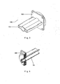
- the solid sample feeding component 100 has an internal cavity 101 (shown in figure 3 in detail) defined therein. One end of the solid sample feeding component 100 is communicated with the sample inlet component 200 through the internal cavity 101, while the other end of the solid sample feeding component 100 is communicated with an inlet 400 of an ion drift tube through the attachment component 300.
- the gaseous sample feeding component 500 includes a body 501 and an external attachment component 502 (as shown in figure 5 in detail).
- the body 501 has a gas channel 503 therein, and the external attachment component 502 includes an inlet hole 504 which is communicated with the gas channel 503.
- the external attachment component 502 is fitted with the sample inlet component 200, the body 501 is inserted into the internal cavity 101, so that a channel of the solid sample feeding component 100 is closed, while only the gas channel 503 of the gaseous sample feeding component 500 is communicated with the inlet 400 of the drift tube of the ion mobility spectrometer.
- FIG 2 it shows the sample inlet component 200.
- the sample inlet component 200 includes a guide groove 201 and a photo diode 202.
- the photo diode 202 detects the sample and then sends a trigger signal.
- an installation hole 203 may be disposed in the sample inlet component.
- the sample inlet component 200 is assembled with other components by the installation hole 203.
- a person skilled in the art also can assemble the sample inlet component with other components by using other conventional means.
- the guide groove 201 has a relatively large opening, so that the collecting paper is easily inserted into the solid sample inlet component 200.
- a radiator is disposed at the photo diode 202, so that the photo diode 202 always operates at a relative low temperature for ensuring the detector performance.
- the internal cavity 101 is in a flat-like shape. Specifically, a central portion of the internal cavity 101 is in the form of arc and two ends of the internal cavity on both sides of the central portion are in the form of square.
- the body 501 of the gaseous sample feeding component 500 is cylindrical. In this way, it can ensure that solid sample feeding efficiency is not affected and the gaseous sample feeding function can also be performed.
- the flat-like shape has a height between 1 and 10 mm, and a width between 15 and 50mm. In the present embodiment, the flat-like shape has a height of 3mm and a width of 22 mm.
- FIGS 6 and 7 are schematic views showing a suction component 600 and a semi-permeable membrane 700, respectively.
- the suction component 600 includes suction holes 601.
- the suction component 600 is attached to the attachment component 300, thereby forming a suction gas flow in order to remove the gaseous sample not entering into the inlet of the drift tube by suction.
- the arrangement and construction of the suction component are described herein only as an example, and thus the person skilled in the art can employ any other conventional technical means in the art to remove the gaseous sample not entering into the inlet of the drift tube by suction.
- the sample feeding device of the present invention also includes a semi-permeable membrane disposed between the inlet 400 of the drift tube and the end of the channel of the internal cavity.
- the semi-permeable membrane can be disposed on the semi-permeable membrane component 700 as shown in figure 7 .
- the semi-permeable membrane component 700 includes suction holes 701 of which a position correspond to a position of the suction holes 601 of the suction component.
- the semi-permeable membrane component 700 further includes auxiliary components such as a mounting 702, and a locking hoop 703 to support and secure the semi-permeable membrane.
- the mounting 702 is made of metal material, and employs aluminium plated with nickel in the present embodiment.
- the locking hoop 703 is made of fluorine rubber (or medical-grade silicone rubber), which is resistant to high temperature and does not emit gaseous foreign substance. Since the material of locking hoop 703 can be resistant to high temperature, i.e. the fluorine rubber is resistant to high temperature of 250°C, it does not adhere to the metal surface.
- the annular outer periphery is capable of securing the soft semi-permeable membrane onto the mounting 702, while ensuring the tightness. It is ensured that the interior of the drift tube is sealed by sealing an outer planar surface of the locking hoop 703 against the suction component 600. A high-temperature state of the semi-permeable membrane is obtained by heat conducted from the sample inlet and the drift tube. It should be understood that the arrangement and construction of the semi-permeable membrane are described herein only as an example, and thus the person skilled in the art can employ any other conventional technical means in the art to achieve this function.
- a recess of the suction component 600 is used to house the semi-permeable membrane component 700.
- a gas flow in front of the semi-permeable membrane is pumped out by two suction holes 601.
- the sample feeding device of the present invention also includes auxiliary components such as an upper cover 800, stay plates 901 and 902, an attachment member 903, and a bottom plate 904 for supporting and attaching.
- the sample feeding device 10 is attached to the drift tube by the attachment member 903.
- sealing devices are disposed between the semi-permeable membrane component and the fixation sample feeding component, the gaseous sample feeding component as well as the inlet of the drift tube to achieve the air-tightness. Since the person skilled in the art can design and produce those components by the conventional technical means in the art, in combination with the practical situation, and those components are not a main part of the present invention, these are not described in detail.
- the solid sample feeding component 100 has the function of quickly heating sample.
- heating components are disposed outside the internal cavity, for example by winding the heating filaments, so that the internal cavity 101 is always kept at a high temperature.
- the sample is vaporized by using laser in the internal cavity 101 for an instant.
- the electrically heating filaments are employed and the internal cavity 101 is surrounded by thermal insulation material, so that the temperature of the solid sample feeding component 100 is kept at 180°C all the time.
- a surface of metal component in the gas path passing the gas is polished or plated with nickel, so that the surface is smooth, thereby reducing the absorption of the gas by the metal component.
- the detecting steps are as follows: the gaseous sample to be detected is input into the body 501 of the gaseous sample feeding component 500 through the gas inlet 504; the gaseous sample to be detected is guided into the inlet 400 of the drift tube of the ion mobility spectrometer through the gas channel of the gaseous sample feeding component 500; and the gaseous sample is detected in the ion mobility spectrometer.
- the gaseous sample feeding component 500 is kept at a high temperature since the gaseous sample feeding component 500 is located in the high-temperature internal cavity 101.
- the process of detecting the sample to be detected by the ion mobility spectrometer including the above sample feeding device includes the following steps:
- the gaseous sample feeding component 500 When performing gaseous sample feeding function, the gaseous sample feeding component 500 is inserted into the solid sample feeding component 100, and the channel of the solid sample feeding component 100 is closed, while only the gas channel of the gaseous sample feeding component 500 acts. Under the action of a high speed suction gas flow, the gaseous sample reaches the semi-permeable membrane after passing through the channel of the gaseous sample feeding component 500. Similarly, a gas flow mass which runs at a high speed and has a large surface area, is formed in the front of the semi-permeable membrane. The sample penetrating through the semi-permeable membrane enters into the ionization region and the drift region so as to be analyzed, thereby obtaining the information about the substance component.
Landscapes
- Chemical & Material Sciences (AREA)
- Physics & Mathematics (AREA)
- Life Sciences & Earth Sciences (AREA)
- Chemical Kinetics & Catalysis (AREA)
- Electrochemistry (AREA)
- Health & Medical Sciences (AREA)
- Spectroscopy & Molecular Physics (AREA)
- Analytical Chemistry (AREA)
- Biochemistry (AREA)
- General Health & Medical Sciences (AREA)
- General Physics & Mathematics (AREA)
- Immunology (AREA)
- Pathology (AREA)
- Sampling And Sample Adjustment (AREA)
- Other Investigation Or Analysis Of Materials By Electrical Means (AREA)
Claims (10)
- Eine Probenzuführvorrichtung für ein lonenmobilitätsspektrometer, die angepasst ist, um eine zu erfassende Probe in einen Einlass (400) einer Driftröhre des lonenmobilitätsspektrometers zu leiten, die eine Feststoffprobenzuführkomponente (400) und eine Gasprobenzuführkomponente (500) aufweist, dadurch gekennzeichnet, dass die Probenzuführvorrichtung (10) ferner folgende Merkmale aufweist:eine Probeneinlasskomponente (200);eine Befestigungskomponente (300), wobei die Feststoffprobenzuführkomponente (100) einen darin definierten Innenhohlraum (101) aufweist, wobei der Innenhohlraum (101) einen Kanal umfasst, ein Ende der Feststoffprobenzuführkomponente (100) mit der Probeneinlasskomponente (200) durch den Innenhohlraum (101) kommuniziert, während das andere Ende der Feststoffprobenzuführkomponente (100) angepasst ist, um mit dem Einlass (400) der Ionendriftröhre durch die Befestigungskomponente (300) zu kommunizieren; und dadurch dassdie Gasprobenzuführkomponente (500) einen Körper (501) und eine externe Befestigungskomponente (502) aufweist, wobei der Körper (501) einen Gaskanal (503) darin aufweist, und die externe Befestigungskomponente (502) ein Einlassloch (504) umfasst, das mit dem Gaskanal (503) kommuniziert, wobei, wenn die externe Befestigungskomponente (502) mit der Probeneinlasskomponente (200) versehen ist, der Körper (501) in den Innenhohlraum (101) eingefügt wird, so dass der Kanal der Feststoffprobenzuführkomponente (100) geschlossen ist, und nur der Gaskanal (503) der Gasprobenzuführkomponente (500) angepasst ist, um mit dem Einlass (400) der Driftröhre des lonenmobilitätsspektrometers zu kommunizieren.
- Die Probenzuführvorrichtung gemäß Anspruch 1, dadurch gekennzeichnet dass:die Probeneinlasskomponente (200) eine Führungsrille (201) und eine Fotodiode (202) aufweist, und die Führungsrille (201) konfiguriert ist, um eine Feststoffprobenlage zu leiten, damit dieselbe in den Innenhohlraum (101) eindringt, und die Fotodiode (202) konfiguriert ist, um die Probe zu erfassen und dann ein Auslösesignal zu senden.
- Die Probenzuführvorrichtung gemäß Anspruch 1 oder 2, dadurch gekennzeichnet dass:die Probenzuführvorrichtung (10) ferner eine semipermeable Membrankomponente (700) aufweist, die ein Saugloch (701), eine Befestigung (702), einen Verriegelungsbügel (703) und eine semipermeable Membran aufweist,wobei eine Position des Sauglochs (701) einer Position eines Sauglochs (601) einer Saugkomponente (600) entspricht, der Verriegelungsbügel (703) einen ringförmigen Außenumfang aufweist, die semipermeable Membran durch den ringförmigen Außenumfang an der Befestigung (702) gesichert ist, und eine Außenoberfläche des Verriegelungsbügels (703) gegen die Saugkomponente (600) abgedichtet ist.
- Die Probenzuführvorrichtung gemäß Anspruch 1, dadurch gekennzeichnet dass:der Innenhohlraum (101) eine flache Form aufweist, ein mittlerer Abschnitt des Innenhohlraums (101) in der Form eines Bogens ist und zwei Enden des Innenhohlraums (101) auf beiden Seiten des mittleren Abschnitts in der Form eines Quadrats sind.
- Die Probenzuführvorrichtung gemäß Anspruch 4, dadurch gekennzeichnet dass:der Innenhohlraum (101) eine Höhe zwischen 1 und 10 mm und eine Breite zwischen 15 und 50 mm aufweist.
- Die Probenzuführvorrichtung gemäß Anspruch 5, dadurch gekennzeichnet dass:der Körper (501) der Gasprobenzuführkomponente (500) in einer zylindrischen Form ist.
- Die Probenzuführvorrichtung gemäß Anspruch 1, dadurch gekennzeichnet dass:die Probenzuführvorrichtung ferner eine Saugkomponente (600) aufweist, die an der Befestigungskomponente (300) befestigt ist, und die Saugkomponente (600) konfiguriert ist, um einen Sauggasfluss zu bilden, um die Gasprobe zu entfernen, die nicht durch Saugen in den Einlass (400) der Driftröhre eindringt.
- Ein Verfahren zum Leiten einer zu erfassenden Feststoffprobe durch Verwenden der Probenzuführvorrichtung gemäß Anspruch 2, das folgende Schritte aufweist:Lösen der Gasprobenzuführkomponente (500) von der Probeneinlasskomponente (200);Einfügen einer Feststoffprobe in den Innenhohlraum (101) der Feststoffprobenzuführkomponente (100) durch die Führungsrille (201) der Probeneinlasskomponente (200);Aussenden eines Auslösesignals durch eine Fotodiode (202) nachdem die Fotodiode (202) die Feststoffprobe erfasst, um eine Heizkomponente zu starten, die außerhalb des Innenhohlraums (101) und des lonenmobilitätsspektrometers angeordnet ist;Verdampfen der Feststoffprobe in dem Innenhohlraum (101) und Leiten der verdampften Feststoffprobe in den Einlass (400) der Driftröhre des lonenmobilitätsspektrometers durch den Innenhohlraum (101); undErfassen der Probe in dem lonenmobilitätsspektrometer.
- Ein Verfahren zum Leiten einer zu erfassenden Gasprobe durch Verwenden der Probenzuführvorrichtung gemäß Anspruch 1, das folgende Schritte aufweist:Einfügen der Gasprobenzuführkomponente (500) in die Probeneinlasskomponente (200);Eingeben einer zu erfassenden Gasprobe in den Körper (501) der Gasprobenzuführkomponente (500) durch einen Gaseinlass;Leiten der zu erfassenden Gasprobe in den Einlass (400) der Driftröhre des Ionenmobilitätsspektrometers durch den Gaskanal (503) der Gasprobenzuführkomponente (500); undErfassen der Probe in dem Ionenmobilitätsspektrometer.
- Ein lonenmobilitätsspektrometer, das folgende Merkmale aufweist:eine Driftröhre, die angepasst ist, um eine zu erfassende Probe, die in das lonenmobilitätsspektrometer geleitet wird, zu ionisieren und zu driften; undein Probenzuführvorrichtung gemäß einem der Ansprüche 1 bis 7, die angepasst ist, um die zu erfassende Probe in einen Einlass (400) der Driftröhre zu leiten.
Priority Applications (1)
| Application Number | Priority Date | Filing Date | Title |
|---|---|---|---|
| PL11778785T PL2492678T3 (pl) | 2010-12-31 | 2011-04-27 | Urządzenie próbkujące dla spektrometru ruchliwości jonów, sposób jego stosowania i spektrometr ruchliwości jonów zawierający urządzenie próbkujące |
Applications Claiming Priority (2)
| Application Number | Priority Date | Filing Date | Title |
|---|---|---|---|
| CN201010624243.4A CN102565181B (zh) | 2010-12-31 | 2010-12-31 | 用于离子迁移谱仪的进样装置及其使用方法和离子迁移谱仪 |
| PCT/CN2011/073390 WO2012088809A1 (zh) | 2010-12-31 | 2011-04-27 | 用于离子迁移谱仪的进样装置、其使用方法及包括它的离子迁移谱仪 |
Publications (3)
| Publication Number | Publication Date |
|---|---|
| EP2492678A1 EP2492678A1 (de) | 2012-08-29 |
| EP2492678A4 EP2492678A4 (de) | 2013-08-21 |
| EP2492678B1 true EP2492678B1 (de) | 2015-07-08 |
Family
ID=45638241
Family Applications (1)
| Application Number | Title | Priority Date | Filing Date |
|---|---|---|---|
| EP11778785.3A Active EP2492678B1 (de) | 2010-12-31 | 2011-04-27 | Probenzufuhrvorrichtung für ein ionenmobilitätsspektrometer, verfahren zu seiner verwendung und ionenmobilitätsspektrometer |
Country Status (5)
| Country | Link |
|---|---|
| US (1) | US8362422B2 (de) |
| EP (1) | EP2492678B1 (de) |
| CN (2) | CN103698387B (de) |
| PL (1) | PL2492678T3 (de) |
| WO (1) | WO2012088809A1 (de) |
Families Citing this family (5)
| Publication number | Priority date | Publication date | Assignee | Title |
|---|---|---|---|---|
| GB201314252D0 (en) * | 2013-08-08 | 2013-09-25 | Smiths Detection Watford Ltd | Apparatus and method |
| CN106996892A (zh) * | 2017-03-28 | 2017-08-01 | 四川出入境检验检疫局检验检疫技术中心 | 食品接触片材特定迁移试验采样浸泡装置 |
| CN111220688A (zh) * | 2018-11-26 | 2020-06-02 | 中国科学院大连化学物理研究所 | 一种带有固液气进样装置的离子迁移谱仪 |
| CN110208039B (zh) * | 2019-06-27 | 2021-12-10 | 山东安准智能科技有限公司 | 一种取样器、快速加热进样系统及快速检测方法 |
| CN112103171B (zh) * | 2020-09-18 | 2023-10-13 | 中国科学院空天信息创新研究院 | 被动进样装置及应用 |
Family Cites Families (19)
| Publication number | Priority date | Publication date | Assignee | Title |
|---|---|---|---|---|
| US5053343A (en) * | 1985-02-15 | 1991-10-01 | Environmental Technologies Group, Inc. | Selective ionization of gas constituents using electrolytic reactions |
| EP0458622A3 (en) * | 1990-05-22 | 1992-01-22 | Barringer Technologies Inc. | Method and apparatus for collection and analysis of desquamated skin particulates or other tissue |
| US7129482B2 (en) * | 1999-07-21 | 2006-10-31 | Sionex Corporation | Explosives detection using differential ion mobility spectrometry |
| US6888128B2 (en) * | 2002-02-15 | 2005-05-03 | Implant Sciences Corporation | Virtual wall gas sampling for an ion mobility spectrometer |
| JP3673789B2 (ja) | 2003-03-31 | 2005-07-20 | 株式会社日立製作所 | 気化ガス検出方法および気化ガス検出装置 |
| US7071465B2 (en) * | 2003-10-14 | 2006-07-04 | Washington State University Research Foundation | Ion mobility spectrometry method and apparatus |
| US7388195B2 (en) * | 2004-09-30 | 2008-06-17 | Charles Stark Draper Laboratory, Inc. | Apparatus and systems for processing samples for analysis via ion mobility spectrometry |
| US7943901B2 (en) * | 2006-11-28 | 2011-05-17 | Excellims Corporation | Practical ion mobility spectrometer apparatus and methods for chemical and/or biological detection |
| CN2927049Y (zh) | 2006-02-21 | 2007-07-25 | 公安部第三研究所 | 气化物质离子迁移率定性分析装置 |
| CN101113969B (zh) * | 2006-07-27 | 2010-05-12 | 中国科学院大连化学物理研究所 | 一种固体、液体样品的进样装置 |
| CN101210910B (zh) * | 2006-12-31 | 2011-03-09 | 同方威视技术股份有限公司 | 气体过滤缓冲一体装置 |
| CN201130166Y (zh) | 2007-08-10 | 2008-10-08 | 上海新漫传感技术研究发展有限公司 | 可用于离子迁移率谱仪的多功能进样装置 |
| CN104849342B (zh) * | 2007-12-27 | 2019-07-30 | 同方威视技术股份有限公司 | 离子迁移谱仪及其方法 |
| CN101728208B (zh) * | 2008-10-20 | 2012-09-26 | 同方威视技术股份有限公司 | 双极性离子迁移谱仪的离子门及方法 |
| CN101752176B (zh) * | 2008-12-17 | 2012-02-08 | 中国科学院大连化学物理研究所 | 一种阵列式离子迁移管 |
| CN201561956U (zh) * | 2009-06-05 | 2010-08-25 | 中国科学院上海应用物理研究所 | 离子迁移谱仪 |
| CN102033100B (zh) * | 2009-09-25 | 2013-03-13 | 同方威视技术股份有限公司 | 使用掺杂剂的离子迁移谱仪(ims)的检测系统及检测方法 |
| CN101819179B (zh) * | 2010-04-01 | 2012-12-12 | 公安部第三研究所 | 一种单管双腔吸气试纸双进样正负离子迁移谱双测管 |
| CN202002909U (zh) * | 2010-12-31 | 2011-10-05 | 同方威视技术股份有限公司 | 用于离子迁移谱仪的进样装置和离子迁移谱仪 |
-
2010
- 2010-12-31 CN CN201310689311.9A patent/CN103698387B/zh active Active
- 2010-12-31 CN CN201010624243.4A patent/CN102565181B/zh active Active
-
2011
- 2011-04-27 US US13/142,500 patent/US8362422B2/en active Active
- 2011-04-27 EP EP11778785.3A patent/EP2492678B1/de active Active
- 2011-04-27 PL PL11778785T patent/PL2492678T3/pl unknown
- 2011-04-27 WO PCT/CN2011/073390 patent/WO2012088809A1/zh not_active Ceased
Also Published As
| Publication number | Publication date |
|---|---|
| PL2492678T3 (pl) | 2015-12-31 |
| US8362422B2 (en) | 2013-01-29 |
| CN102565181B (zh) | 2014-04-09 |
| WO2012088809A1 (zh) | 2012-07-05 |
| CN103698387A (zh) | 2014-04-02 |
| CN102565181A (zh) | 2012-07-11 |
| EP2492678A4 (de) | 2013-08-21 |
| CN103698387B (zh) | 2016-03-23 |
| EP2492678A1 (de) | 2012-08-29 |
| US20120168616A1 (en) | 2012-07-05 |
Similar Documents
| Publication | Publication Date | Title |
|---|---|---|
| JP6042965B2 (ja) | 試料導入装置 | |
| CN109755097B (zh) | 一种四极杆质谱仪及其使用方法 | |
| US8304716B2 (en) | Sampling device for ion migration spectrometer and method for using the same, and ion migration spectrometer | |
| US8161830B2 (en) | Method, apparatus, and system for integrated vapor and particulate sampling | |
| US8362422B2 (en) | Sample feeding device for ion mobility spectrometer, method of using the same and ion mobility spectrometer | |
| JP4303499B2 (ja) | 化学剤の探知装置 | |
| US10665446B2 (en) | Surface layer disruption and ionization utilizing an extreme ultraviolet radiation source | |
| RU2759819C2 (ru) | Система впускного потока для пробоотборника | |
| CN106525523B (zh) | 一种用于离子迁移谱仪的热解析进样器 | |
| EP1724575A1 (de) | Gasüberwachungsvorrichtung | |
| EP2520922B1 (de) | Probeneinführungsvorrichtung für ein spurenerkennungsmessgerät und spurenerkennungsmessgerät mit der probeneinführungsvorrichtung | |
| JP3787116B2 (ja) | 化学剤の探知方法 | |
| KR102583117B1 (ko) | 분석 기기에 입자 함유 샘플을 도입하기 위한 시스템 및 사용 방법 | |
| EP2423663B1 (de) | Spurennachweisvorrichtung und analyseverfahren dafür | |
| WO2015159714A1 (ja) | 質量分析装置および質量分析装置に用いられるカートリッジ | |
| CN110873753B (zh) | 一种分离全血样品中气相游离丙泊酚的富集方法 | |
| KR20250005222A (ko) | 검출기 유입구 및 방법 | |
| US7270020B2 (en) | Instrument assemblies and analysis methods | |
| CN113945431A (zh) | 一种痕量物质取样装置、分析系统及取样方法 | |
| JP2009047710A (ja) | 化学剤の探知方法 | |
| RU2305282C2 (ru) | Десорбер для детектора с разделением ионов по подвижности | |
| HK1172083B (en) | Sample injection device for ion mobility spectrometer, ion mobility spectrometer, and method for operating such an ion mobility spectrometer | |
| HK1172083A (en) | Sample injection device for ion mobility spectrometer, ion mobility spectrometer, and method for operating such an ion mobility spectrometer | |
| JP2005166373A (ja) | 飛行時間型質量分析装置および該装置を備えた固形試料不純物分析装置 | |
| HK1172149B (en) | Sampling device for ion migration spectrometer and method for using the same, and ion migration spectrometer |
Legal Events
| Date | Code | Title | Description |
|---|---|---|---|
| PUAI | Public reference made under article 153(3) epc to a published international application that has entered the european phase |
Free format text: ORIGINAL CODE: 0009012 |
|
| 17P | Request for examination filed |
Effective date: 20111114 |
|
| AK | Designated contracting states |
Kind code of ref document: A1 Designated state(s): AL AT BE BG CH CY CZ DE DK EE ES FI FR GB GR HR HU IE IS IT LI LT LU LV MC MK MT NL NO PL PT RO RS SE SI SK SM TR |
|
| R17P | Request for examination filed (corrected) |
Effective date: 20111114 |
|
| R17P | Request for examination filed (corrected) |
Effective date: 20111114 |
|
| RIC1 | Information provided on ipc code assigned before grant |
Ipc: H01J 49/04 20060101ALI20130218BHEP Ipc: H01J 49/40 20060101AFI20130218BHEP Ipc: G01N 27/64 20060101ALI20130218BHEP |
|
| REG | Reference to a national code |
Ref country code: DE Ref legal event code: R079 Ref document number: 602011017741 Country of ref document: DE Free format text: PREVIOUS MAIN CLASS: G01N0027640000 Ipc: H01J0049400000 |
|
| A4 | Supplementary search report drawn up and despatched |
Effective date: 20130722 |
|
| RIC1 | Information provided on ipc code assigned before grant |
Ipc: H01J 49/04 20060101ALI20130716BHEP Ipc: H01J 49/40 20060101AFI20130716BHEP Ipc: G01N 27/64 20060101ALI20130716BHEP |
|
| DAX | Request for extension of the european patent (deleted) | ||
| 17Q | First examination report despatched |
Effective date: 20140606 |
|
| GRAP | Despatch of communication of intention to grant a patent |
Free format text: ORIGINAL CODE: EPIDOSNIGR1 |
|
| INTG | Intention to grant announced |
Effective date: 20150126 |
|
| GRAS | Grant fee paid |
Free format text: ORIGINAL CODE: EPIDOSNIGR3 |
|
| GRAA | (expected) grant |
Free format text: ORIGINAL CODE: 0009210 |
|
| AK | Designated contracting states |
Kind code of ref document: B1 Designated state(s): AL AT BE BG CH CY CZ DE DK EE ES FI FR GB GR HR HU IE IS IT LI LT LU LV MC MK MT NL NO PL PT RO RS SE SI SK SM TR |
|
| REG | Reference to a national code |
Ref country code: GB Ref legal event code: FG4D |
|
| REG | Reference to a national code |
Ref country code: AT Ref legal event code: REF Ref document number: 735967 Country of ref document: AT Kind code of ref document: T Effective date: 20150715 Ref country code: CH Ref legal event code: EP |
|
| REG | Reference to a national code |
Ref country code: IE Ref legal event code: FG4D |
|
| REG | Reference to a national code |
Ref country code: DE Ref legal event code: R096 Ref document number: 602011017741 Country of ref document: DE |
|
| REG | Reference to a national code |
Ref country code: AT Ref legal event code: MK05 Ref document number: 735967 Country of ref document: AT Kind code of ref document: T Effective date: 20150708 |
|
| REG | Reference to a national code |
Ref country code: NL Ref legal event code: MP Effective date: 20150708 |
|
| REG | Reference to a national code |
Ref country code: LT Ref legal event code: MG4D |
|
| REG | Reference to a national code |
Ref country code: PL Ref legal event code: T3 |
|
| PG25 | Lapsed in a contracting state [announced via postgrant information from national office to epo] |
Ref country code: LT Free format text: LAPSE BECAUSE OF FAILURE TO SUBMIT A TRANSLATION OF THE DESCRIPTION OR TO PAY THE FEE WITHIN THE PRESCRIBED TIME-LIMIT Effective date: 20150708 Ref country code: FI Free format text: LAPSE BECAUSE OF FAILURE TO SUBMIT A TRANSLATION OF THE DESCRIPTION OR TO PAY THE FEE WITHIN THE PRESCRIBED TIME-LIMIT Effective date: 20150708 Ref country code: GR Free format text: LAPSE BECAUSE OF FAILURE TO SUBMIT A TRANSLATION OF THE DESCRIPTION OR TO PAY THE FEE WITHIN THE PRESCRIBED TIME-LIMIT Effective date: 20151009 Ref country code: NO Free format text: LAPSE BECAUSE OF FAILURE TO SUBMIT A TRANSLATION OF THE DESCRIPTION OR TO PAY THE FEE WITHIN THE PRESCRIBED TIME-LIMIT Effective date: 20151008 Ref country code: LV Free format text: LAPSE BECAUSE OF FAILURE TO SUBMIT A TRANSLATION OF THE DESCRIPTION OR TO PAY THE FEE WITHIN THE PRESCRIBED TIME-LIMIT Effective date: 20150708 |
|
| PG25 | Lapsed in a contracting state [announced via postgrant information from national office to epo] |
Ref country code: PT Free format text: LAPSE BECAUSE OF FAILURE TO SUBMIT A TRANSLATION OF THE DESCRIPTION OR TO PAY THE FEE WITHIN THE PRESCRIBED TIME-LIMIT Effective date: 20151109 Ref country code: SE Free format text: LAPSE BECAUSE OF FAILURE TO SUBMIT A TRANSLATION OF THE DESCRIPTION OR TO PAY THE FEE WITHIN THE PRESCRIBED TIME-LIMIT Effective date: 20150708 Ref country code: ES Free format text: LAPSE BECAUSE OF FAILURE TO SUBMIT A TRANSLATION OF THE DESCRIPTION OR TO PAY THE FEE WITHIN THE PRESCRIBED TIME-LIMIT Effective date: 20150708 Ref country code: AT Free format text: LAPSE BECAUSE OF FAILURE TO SUBMIT A TRANSLATION OF THE DESCRIPTION OR TO PAY THE FEE WITHIN THE PRESCRIBED TIME-LIMIT Effective date: 20150708 Ref country code: IS Free format text: LAPSE BECAUSE OF FAILURE TO SUBMIT A TRANSLATION OF THE DESCRIPTION OR TO PAY THE FEE WITHIN THE PRESCRIBED TIME-LIMIT Effective date: 20151108 Ref country code: HR Free format text: LAPSE BECAUSE OF FAILURE TO SUBMIT A TRANSLATION OF THE DESCRIPTION OR TO PAY THE FEE WITHIN THE PRESCRIBED TIME-LIMIT Effective date: 20150708 Ref country code: RS Free format text: LAPSE BECAUSE OF FAILURE TO SUBMIT A TRANSLATION OF THE DESCRIPTION OR TO PAY THE FEE WITHIN THE PRESCRIBED TIME-LIMIT Effective date: 20150708 |
|
| REG | Reference to a national code |
Ref country code: DE Ref legal event code: R097 Ref document number: 602011017741 Country of ref document: DE |
|
| PG25 | Lapsed in a contracting state [announced via postgrant information from national office to epo] |
Ref country code: SK Free format text: LAPSE BECAUSE OF FAILURE TO SUBMIT A TRANSLATION OF THE DESCRIPTION OR TO PAY THE FEE WITHIN THE PRESCRIBED TIME-LIMIT Effective date: 20150708 Ref country code: DK Free format text: LAPSE BECAUSE OF FAILURE TO SUBMIT A TRANSLATION OF THE DESCRIPTION OR TO PAY THE FEE WITHIN THE PRESCRIBED TIME-LIMIT Effective date: 20150708 Ref country code: CZ Free format text: LAPSE BECAUSE OF FAILURE TO SUBMIT A TRANSLATION OF THE DESCRIPTION OR TO PAY THE FEE WITHIN THE PRESCRIBED TIME-LIMIT Effective date: 20150708 Ref country code: IT Free format text: LAPSE BECAUSE OF FAILURE TO SUBMIT A TRANSLATION OF THE DESCRIPTION OR TO PAY THE FEE WITHIN THE PRESCRIBED TIME-LIMIT Effective date: 20150708 Ref country code: EE Free format text: LAPSE BECAUSE OF FAILURE TO SUBMIT A TRANSLATION OF THE DESCRIPTION OR TO PAY THE FEE WITHIN THE PRESCRIBED TIME-LIMIT Effective date: 20150708 |
|
| PLBE | No opposition filed within time limit |
Free format text: ORIGINAL CODE: 0009261 |
|
| STAA | Information on the status of an ep patent application or granted ep patent |
Free format text: STATUS: NO OPPOSITION FILED WITHIN TIME LIMIT |
|
| PG25 | Lapsed in a contracting state [announced via postgrant information from national office to epo] |
Ref country code: RO Free format text: LAPSE BECAUSE OF FAILURE TO SUBMIT A TRANSLATION OF THE DESCRIPTION OR TO PAY THE FEE WITHIN THE PRESCRIBED TIME-LIMIT Effective date: 20150708 |
|
| 26N | No opposition filed |
Effective date: 20160411 |
|
| PG25 | Lapsed in a contracting state [announced via postgrant information from national office to epo] |
Ref country code: BE Free format text: LAPSE BECAUSE OF NON-PAYMENT OF DUE FEES Effective date: 20160430 Ref country code: SI Free format text: LAPSE BECAUSE OF FAILURE TO SUBMIT A TRANSLATION OF THE DESCRIPTION OR TO PAY THE FEE WITHIN THE PRESCRIBED TIME-LIMIT Effective date: 20150708 |
|
| REG | Reference to a national code |
Ref country code: CH Ref legal event code: PL |
|
| PG25 | Lapsed in a contracting state [announced via postgrant information from national office to epo] |
Ref country code: BE Free format text: LAPSE BECAUSE OF FAILURE TO SUBMIT A TRANSLATION OF THE DESCRIPTION OR TO PAY THE FEE WITHIN THE PRESCRIBED TIME-LIMIT Effective date: 20150708 Ref country code: LU Free format text: LAPSE BECAUSE OF FAILURE TO SUBMIT A TRANSLATION OF THE DESCRIPTION OR TO PAY THE FEE WITHIN THE PRESCRIBED TIME-LIMIT Effective date: 20160427 |
|
| REG | Reference to a national code |
Ref country code: IE Ref legal event code: MM4A |
|
| REG | Reference to a national code |
Ref country code: FR Ref legal event code: ST Effective date: 20161230 |
|
| PG25 | Lapsed in a contracting state [announced via postgrant information from national office to epo] |
Ref country code: FR Free format text: LAPSE BECAUSE OF NON-PAYMENT OF DUE FEES Effective date: 20160502 Ref country code: LI Free format text: LAPSE BECAUSE OF NON-PAYMENT OF DUE FEES Effective date: 20160430 Ref country code: CH Free format text: LAPSE BECAUSE OF NON-PAYMENT OF DUE FEES Effective date: 20160430 |
|
| PG25 | Lapsed in a contracting state [announced via postgrant information from national office to epo] |
Ref country code: IE Free format text: LAPSE BECAUSE OF NON-PAYMENT OF DUE FEES Effective date: 20160427 |
|
| PG25 | Lapsed in a contracting state [announced via postgrant information from national office to epo] |
Ref country code: NL Free format text: LAPSE BECAUSE OF FAILURE TO SUBMIT A TRANSLATION OF THE DESCRIPTION OR TO PAY THE FEE WITHIN THE PRESCRIBED TIME-LIMIT Effective date: 20150708 |
|
| PG25 | Lapsed in a contracting state [announced via postgrant information from national office to epo] |
Ref country code: HU Free format text: LAPSE BECAUSE OF FAILURE TO SUBMIT A TRANSLATION OF THE DESCRIPTION OR TO PAY THE FEE WITHIN THE PRESCRIBED TIME-LIMIT; INVALID AB INITIO Effective date: 20110427 Ref country code: CY Free format text: LAPSE BECAUSE OF FAILURE TO SUBMIT A TRANSLATION OF THE DESCRIPTION OR TO PAY THE FEE WITHIN THE PRESCRIBED TIME-LIMIT Effective date: 20150708 Ref country code: SM Free format text: LAPSE BECAUSE OF FAILURE TO SUBMIT A TRANSLATION OF THE DESCRIPTION OR TO PAY THE FEE WITHIN THE PRESCRIBED TIME-LIMIT Effective date: 20150708 |
|
| PG25 | Lapsed in a contracting state [announced via postgrant information from national office to epo] |
Ref country code: MT Free format text: LAPSE BECAUSE OF NON-PAYMENT OF DUE FEES Effective date: 20160430 Ref country code: TR Free format text: LAPSE BECAUSE OF FAILURE TO SUBMIT A TRANSLATION OF THE DESCRIPTION OR TO PAY THE FEE WITHIN THE PRESCRIBED TIME-LIMIT Effective date: 20150708 Ref country code: MK Free format text: LAPSE BECAUSE OF FAILURE TO SUBMIT A TRANSLATION OF THE DESCRIPTION OR TO PAY THE FEE WITHIN THE PRESCRIBED TIME-LIMIT Effective date: 20150708 Ref country code: MC Free format text: LAPSE BECAUSE OF FAILURE TO SUBMIT A TRANSLATION OF THE DESCRIPTION OR TO PAY THE FEE WITHIN THE PRESCRIBED TIME-LIMIT Effective date: 20150708 |
|
| PG25 | Lapsed in a contracting state [announced via postgrant information from national office to epo] |
Ref country code: BG Free format text: LAPSE BECAUSE OF FAILURE TO SUBMIT A TRANSLATION OF THE DESCRIPTION OR TO PAY THE FEE WITHIN THE PRESCRIBED TIME-LIMIT Effective date: 20150708 |
|
| PG25 | Lapsed in a contracting state [announced via postgrant information from national office to epo] |
Ref country code: AL Free format text: LAPSE BECAUSE OF FAILURE TO SUBMIT A TRANSLATION OF THE DESCRIPTION OR TO PAY THE FEE WITHIN THE PRESCRIBED TIME-LIMIT Effective date: 20150708 |
|
| PGFP | Annual fee paid to national office [announced via postgrant information from national office to epo] |
Ref country code: PL Payment date: 20200311 Year of fee payment: 10 |
|
| PGFP | Annual fee paid to national office [announced via postgrant information from national office to epo] |
Ref country code: GB Payment date: 20200416 Year of fee payment: 10 |
|
| GBPC | Gb: european patent ceased through non-payment of renewal fee |
Effective date: 20210427 |
|
| PG25 | Lapsed in a contracting state [announced via postgrant information from national office to epo] |
Ref country code: GB Free format text: LAPSE BECAUSE OF NON-PAYMENT OF DUE FEES Effective date: 20210427 |
|
| PG25 | Lapsed in a contracting state [announced via postgrant information from national office to epo] |
Ref country code: PL Free format text: LAPSE BECAUSE OF NON-PAYMENT OF DUE FEES Effective date: 20210427 |
|
| P01 | Opt-out of the competence of the unified patent court (upc) registered |
Effective date: 20230526 |
|
| PGFP | Annual fee paid to national office [announced via postgrant information from national office to epo] |
Ref country code: DE Payment date: 20250417 Year of fee payment: 15 |