EP2492628A1 - Swirl reducing gas turbine engine recuperator - Google Patents
Swirl reducing gas turbine engine recuperator Download PDFInfo
- Publication number
- EP2492628A1 EP2492628A1 EP12157309A EP12157309A EP2492628A1 EP 2492628 A1 EP2492628 A1 EP 2492628A1 EP 12157309 A EP12157309 A EP 12157309A EP 12157309 A EP12157309 A EP 12157309A EP 2492628 A1 EP2492628 A1 EP 2492628A1
- Authority
- EP
- European Patent Office
- Prior art keywords
- exhaust
- recuperator
- passages
- inlet
- flow
- Prior art date
- Legal status (The legal status is an assumption and is not a legal conclusion. Google has not performed a legal analysis and makes no representation as to the accuracy of the status listed.)
- Granted
Links
Images


Classifications
-
- F—MECHANICAL ENGINEERING; LIGHTING; HEATING; WEAPONS; BLASTING
- F28—HEAT EXCHANGE IN GENERAL
- F28D—HEAT-EXCHANGE APPARATUS, NOT PROVIDED FOR IN ANOTHER SUBCLASS, IN WHICH THE HEAT-EXCHANGE MEDIA DO NOT COME INTO DIRECT CONTACT
- F28D21/00—Heat-exchange apparatus not covered by any of the groups F28D1/00 - F28D20/00
- F28D21/0001—Recuperative heat exchangers
- F28D21/0003—Recuperative heat exchangers the heat being recuperated from exhaust gases
-
- F—MECHANICAL ENGINEERING; LIGHTING; HEATING; WEAPONS; BLASTING
- F02—COMBUSTION ENGINES; HOT-GAS OR COMBUSTION-PRODUCT ENGINE PLANTS
- F02C—GAS-TURBINE PLANTS; AIR INTAKES FOR JET-PROPULSION PLANTS; CONTROLLING FUEL SUPPLY IN AIR-BREATHING JET-PROPULSION PLANTS
- F02C7/00—Features, components parts, details or accessories, not provided for in, or of interest apart form groups F02C1/00 - F02C6/00; Air intakes for jet-propulsion plants
- F02C7/08—Heating air supply before combustion, e.g. by exhaust gases
- F02C7/10—Heating air supply before combustion, e.g. by exhaust gases by means of regenerative heat-exchangers
-
- F—MECHANICAL ENGINEERING; LIGHTING; HEATING; WEAPONS; BLASTING
- F02—COMBUSTION ENGINES; HOT-GAS OR COMBUSTION-PRODUCT ENGINE PLANTS
- F02C—GAS-TURBINE PLANTS; AIR INTAKES FOR JET-PROPULSION PLANTS; CONTROLLING FUEL SUPPLY IN AIR-BREATHING JET-PROPULSION PLANTS
- F02C7/00—Features, components parts, details or accessories, not provided for in, or of interest apart form groups F02C1/00 - F02C6/00; Air intakes for jet-propulsion plants
- F02C7/12—Cooling of plants
- F02C7/14—Cooling of plants of fluids in the plant, e.g. lubricant or fuel
- F02C7/141—Cooling of plants of fluids in the plant, e.g. lubricant or fuel of working fluid
- F02C7/143—Cooling of plants of fluids in the plant, e.g. lubricant or fuel of working fluid before or between the compressor stages
-
- F—MECHANICAL ENGINEERING; LIGHTING; HEATING; WEAPONS; BLASTING
- F28—HEAT EXCHANGE IN GENERAL
- F28D—HEAT-EXCHANGE APPARATUS, NOT PROVIDED FOR IN ANOTHER SUBCLASS, IN WHICH THE HEAT-EXCHANGE MEDIA DO NOT COME INTO DIRECT CONTACT
- F28D9/00—Heat-exchange apparatus having stationary plate-like or laminated conduit assemblies for both heat-exchange media, the media being in contact with different sides of a conduit wall
- F28D9/0012—Heat-exchange apparatus having stationary plate-like or laminated conduit assemblies for both heat-exchange media, the media being in contact with different sides of a conduit wall the apparatus having an annular form
- F28D9/0018—Heat-exchange apparatus having stationary plate-like or laminated conduit assemblies for both heat-exchange media, the media being in contact with different sides of a conduit wall the apparatus having an annular form without any annular circulation of the heat exchange media
-
- F—MECHANICAL ENGINEERING; LIGHTING; HEATING; WEAPONS; BLASTING
- F28—HEAT EXCHANGE IN GENERAL
- F28F—DETAILS OF HEAT-EXCHANGE AND HEAT-TRANSFER APPARATUS, OF GENERAL APPLICATION
- F28F2250/00—Arrangements for modifying the flow of the heat exchange media, e.g. flow guiding means; Particular flow patterns
- F28F2250/10—Particular pattern of flow of the heat exchange media
- F28F2250/102—Particular pattern of flow of the heat exchange media with change of flow direction
-
- F—MECHANICAL ENGINEERING; LIGHTING; HEATING; WEAPONS; BLASTING
- F28—HEAT EXCHANGE IN GENERAL
- F28F—DETAILS OF HEAT-EXCHANGE AND HEAT-TRANSFER APPARATUS, OF GENERAL APPLICATION
- F28F2265/00—Safety or protection arrangements; Arrangements for preventing malfunction
- F28F2265/26—Safety or protection arrangements; Arrangements for preventing malfunction for allowing differential expansion between elements
-
- F—MECHANICAL ENGINEERING; LIGHTING; HEATING; WEAPONS; BLASTING
- F28—HEAT EXCHANGE IN GENERAL
- F28F—DETAILS OF HEAT-EXCHANGE AND HEAT-TRANSFER APPARATUS, OF GENERAL APPLICATION
- F28F2265/00—Safety or protection arrangements; Arrangements for preventing malfunction
- F28F2265/30—Safety or protection arrangements; Arrangements for preventing malfunction for preventing vibrations
-
- Y—GENERAL TAGGING OF NEW TECHNOLOGICAL DEVELOPMENTS; GENERAL TAGGING OF CROSS-SECTIONAL TECHNOLOGIES SPANNING OVER SEVERAL SECTIONS OF THE IPC; TECHNICAL SUBJECTS COVERED BY FORMER USPC CROSS-REFERENCE ART COLLECTIONS [XRACs] AND DIGESTS
- Y02—TECHNOLOGIES OR APPLICATIONS FOR MITIGATION OR ADAPTATION AGAINST CLIMATE CHANGE
- Y02T—CLIMATE CHANGE MITIGATION TECHNOLOGIES RELATED TO TRANSPORTATION
- Y02T50/00—Aeronautics or air transport
- Y02T50/60—Efficient propulsion technologies, e.g. for aircraft
Definitions
- the application relates generally to a recuperator for a gas turbine engine and, more particularly, to such a recuperator allowing for reduction of the swirl in the exhaust flow.
- Gas turbine engines may include a recuperator, which is a heat exchanger using hot exhaust gas from the engine to heat the compressed air exiting the compressor prior to circulation of the compressed air to the combustion chamber. Preheating the compressed air usually improves fuel efficiency of the engine.
- the recuperator reduces the heat of exhaust gas, which helps minimize the infrared signature of the aircraft.
- Axial or radial air entry swirlers are generally used during combustion in order to stabilize the flame and promote mixing. However, this usually results in a relatively important swirl component in the exhaust flow exiting the turbine section.
- deswirling vanes are provided between the turbine section and the exhaust mixer of the engine to reduce the swirl of the exhaust flow, such as to convert the kinetic energy of the flow into increased thrust.
- a recuperator configured to extend within an exhaust duct of a gas turbine engine, the recuperator comprising exhaust passages providing fluid flow communication between an exhaust inlet and an exhaust outlet, the exhaust inlet being oriented to receive exhaust flow from a turbine of the engine and the exhaust outlet being oriented to deliver the exhaust flow to atmosphere, the exhaust passages having an arcuate profile in a plane perpendicular to a central axis of the recuperator to reduce a swirl of the exhaust flow, air passages in heat exchange relationship with the exhaust passages and providing fluid flow communication between an air inlet and an air outlet, an inlet connection member defining the air inlet and being designed to sealingly engage a first plenum in fluid flow communication with a compressor discharge of the gas turbine engine, and an outlet connection member defining the air outlet and being designed to sealingly engage a second plenum containing a compressor of the gas turbine engine.
- the recuperator may include circumferential splitters extending upstream from the exhaust inlet and curved in the plane perpendicular to the central axis of the recuperator to reduce the swirl of the exhaust flow.
- a gas turbine engine comprising a compressor section having a discharge in fluid flow communication with a first plenum, a combustor contained in a second plenum, a turbine section in fluid flow communication with the combustor, an exhaust duct in fluid flow communication with the turbine section, and a recuperator located in the exhaust duct, the recuperator defining: exhaust passages providing fluid flow communication between an exhaust inlet and an exhaust outlet, the exhaust inlet and exhaust outlet extending across the exhaust duct with the exhaust inlet being in fluid flow communication with the turbine section, the exhaust passages having an arcuate profile in a plane perpendicular to a central axis of the recuperator to reduce a swirl of the exhaust flow, air passages in heat exchange relationship with the exhaust passages and providing fluid flow communication between an air inlet and an air outlet, an inlet connection member defining the air inlet and sealingly engaging the first plenum to receive pressurized air from the compressor, and an outlet connection member defining the air outlet and sealingly engaging the second ple
- the gas turbine engine may further include circumferential splitters extending within the exhaust duct upstream of the exhaust inlet.
- the splitters may be supported by radially extending struts having an asymmetrical airfoil shape twisted to reduce the swirl of the exhaust flow.
- the splitters may extend from the exhaust inlet and form part of the recuperator.
- a method of deswirling and cooling an exhaust flow in an exhaust duct of a gas turbine engine comprising circulating the exhaust flow from a turbine section of the gas turbine engine to a recuperator extending within the exhaust duct, circulating air discharged from a compressor section to a combustor of the gas turbine engine through air passages of the recuperator, and deswirling and diffusing the exhaust flow by circulating the exhaust flow through exhaust passages of the recuperator having an arcuate profile in a plane perpendicular.
- Fig.1 illustrates a gas turbine engine 10 of a type preferably provided for use in subsonic flight, generally comprising in serial flow communication a fan 12 through which ambient air is propelled, a compressor section 14 for pressurizing the air, a combustor 16 in which the compressed air is mixed with fuel and ignited for generating an annular stream of hot combustion gases, and a turbine section 18 for extracting energy from the combustion gases.
- the compressor section 14 and combustor 16 are typically in serial flow communication with one another through a gas generator case 22 which contains the combustor 16 and which receives the flow from the compressor discharge, which in the embodiment shown is in the form of diffuser pipes 20.
- the combustion gases flowing out of the combustor 16 circulate through the turbine section 18 and are then expelled through an exhaust duct 24.
- gas turbine engine 10 may alternately be another type of engine, for example a turboshaft engine, also generally comprising in serial flow communication a compressor section, a combustor, and a turbine section, and a propeller shaft supporting a propeller and rotated by a low pressure portion of the turbine section through a reduction gearbox.
- a turboshaft engine also generally comprising in serial flow communication a compressor section, a combustor, and a turbine section, and a propeller shaft supporting a propeller and rotated by a low pressure portion of the turbine section through a reduction gearbox.
- the gas generator case 22 is separated in at least two plenums, including a plenum 26 containing the combustor 16, and another plenum 28 in fluid flow communication with the diffuser pipes 20 of the compressor section 14.
- a recuperator 30 extends across the exhaust duct 24, such that the exhaust gas from the turbine section 18 circulates therethrough.
- the recuperator 30 also provides the fluid flow communication between the combustor plenum 26 and the compressor plenum 28, as will be further detailed below.
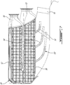
- the recuperator 30 includes a plurality of arcuate segments 32, which function independently from one another and are connected to the engine 10 independently from one another, and which together define the annular shape of the recuperator 30.
- a controlled gap 34 (see Fig. 4 ) is provided between adjacent ones of the segments 32 to allow for thermal expansion without interference.
- the segments 32 are sized to extend between adjacent structural struts 36 (see Fig. 3 ) of the engine 10, and as such the gap 34 is sized to allow for thermal expansion of each segment 32 without major interference with the strut 36 extending in the gap 34.
- a compressible side plate 46 at the side of the segment 32 provides sealing with the strut 36 and vibrational damping during engine operation.
- each segment 32 is sized and located such as to be removable from the outside of the engine 10 through an opening accessible when the exhaust scroll 38 (see Fig. 2 ) is removed.
- the exhaust scroll 38 that is removable on the wing, such a configuration allows for the recuperator segments 32 to be removed and replaced if necessary with the engine 10 remaining on the wing.
- each segment 32 defines a plate heat exchanger, with a first group of fluid passages 40 for circulating the compressed air, and a second group of fluid passages 42 for circulating the exhaust gas.
- the air and exhaust passages 40, 42 alternate and are in heat transfer relationship with one another.
- the air and exhaust passages 40, 42 are relatively oriented such as to define a mixed counter flow and double pass cross flow heat exchanger.
- a panel assembly 44 thus defines the alternating U-shaped first fluid passages 40 and curved second fluid passages 42.
- the panels 44 are made of a nickel alloy and are brazed to one another.
- the side plates 46 and a rear bulkhead 48 respectively seal the opposed side ends and the rear end of the panel assembly 44.
- the bulkhead 48 also provides vibrational damping of the segment 32 during engine operation.
- the exhaust fluid passages 42 communicate with a same exhaust inlet 50 defined by the radially inward end of the segment 32 and with a same exhaust outlet 52 defined by the radially outward end of the segment 32.
- the exhaust inlet and outlet 50, 52 extend across the exhaust duct 24, with the exhaust inlet 50 located in proximity of the turbine section 18.
- the air passages 40 communicate with a same air inlet 56 defined at one end thereof and with a same air outlet 72 defined at the opposed end thereof.
- the air inlet 56 is defined by an inlet connection member 58 which is designed to sealingly engage the compressor plenum 28 for receiving the compressed air.
- the air inlet 56 is oriented such that the compressed air flows axially or approximately axially therethrough.
- the inlet connection member 58 includes a duct 60 having one end connected to an inlet bulkhead 62 attached to the panel assembly 44, and an opposed end having a flange 64 extending outwardly therearound. Referring to Fig.
- the inlet connection member 58 also includes a flexible duct member 66 having a first end rigidly connected to the flange 64, for example through an appropriate type of fasteners with a compressible seal ring or a gasket (not shown) therebetween. A second end of the flexible duct member 66 is rigidly connected to the compressor plenum 28.
- the flexible duct member 66 includes two rigid duct portions 68 interconnected by a diaphragm 70, which allows relative movement between the two duct portions 68; alternately, the entire flexible duct member 66 may be made of flexible material.
- flexible duct member is intended herein to designate a duct member which includes at least a flexible portion such as to allow for relative movement between its opposed ends.
- the inlet connection member 58 thus defines a floating connection with the compressor plenum 28, such that some amount of axial and radial relative motion is allowed therebetween.
- the air outlet 72 is defined by an outlet connection member 74 which is designed to sealingly engage the combustor plenum 26 for delivering the heated compressed air to the combustor 16.
- the air outlet 72 is oriented such that the heated compressed air flows axially or approximately axially therethrough.
- the outlet connection member 74 includes a duct 76 having one end connected to an outlet bulkhead 78 attached to the panel assembly 44, and an opposed end having a flange 80 extending outwardly therearound.
- the flange 80 is rigidly connected to the combustor plenum 26, for example through an appropriate type of fasteners.
- a compressible seal ring or a gasket (not shown) is received between the flanged 80 and the plenum 26 to form a sealed connection.
- the outlet connection member 74 thus defines a rigid connection with the combustor plenum 26.
- the inlet connection member 58 may define a rigid connection with the compressor plenum 28, with the outlet connection member 74 defining a floating connection with the combustor plenum 26.
- the rear bulkhead 48 includes a protrusion 82 which is designed to be the contact point between the segment 32 and the wall 84 of the exhaust duct 24, in order to stabilize the position of the segment 32 within the exhaust duct 24.
- the protrusion 82 facilitates the relative sliding motion between the rear bulkhead 48 and the exhaust duct wall 84 when relative movement due to the floating connection occurs, and acts as a control surface maintaining contact between the segment 32 and the exhaust duct wall 84.
- the exhaust passages 42 have a flaring shape, i.e. the cross-sectional area of each exhaust passage 42 increases from the exhaust inlet 50 to the exhaust outlet 52, such as to diffuse the exhaust flow.
- the exhaust inlet 50 thus has a smaller cross-sectional area than that of the exhaust outlet 52.
- a concentric split diffuser 53 is provided in the exhaust duct 24 upstream of the exhaust inlet 50.
- the diffuser 53 includes circumferential splitters 54 which are supported by radial struts 55.
- the splitters 54 progressively curve from the axial direction at the upstream end toward the radial direction.
- the splitters 54 define passages having a flaring shape, i.e.
- Diffuser vanes 51 may also be provided at the exit of the power turbine, upstream of the split diffuser 53. The diffusion of the exhaust flow allows for an improved heat exchange within the recuperator 30.
- the concentric split diffuser 53' including splitters 54' and radial struts 55' forms part of the recuperator 30, and extends from the exhaust inlet 50.
- the recuperator 30 also reduces the swirl of the exhaust flow.
- the exhaust passages 42 have an arcuate profile in a plane perpendicular to a central axis C of the recuperator to reduce the exhaust flow swirl.
- the splitters 54 ( Fig. 2 ) may also be curved in the plane perpendicular to the central axis of the recuperator.
- the radial struts 55, 55' which are structural members supporting the splitters 54, 54' ( Figs. 2 and 7 ) have an asymmetrical airfoil shape twisted to allow a progressively increased swirl with increasing radius, optimised to reduce the turning losses as the flow turns from the axial to the radial direction within the diffuser 53, 53'.
- the vanes 51 may also have an asymmetrical airfoil shape similar to the struts 55, 55'.
- the swirl i.e. the circumferential component of the flow velocity at the power turbine exit, is thus first slowed in the diffuser vanes 51.
- the flow exiting the vanes 51 enter the split diffuser 53, 53'.
- the flow in the split diffuser 53, 53' slows down both in the axial direction due to the splitters 54, 54' as well as in circumferential direction, i.e. the swirl, due to the increased radius of the swirling shape of the radial struts 55, 55'.
- the recuperator 130 includes a plurality of independent arcuate segments 132, with a controlled gap 134 being defined between adjacent segments 132 for thermal expansion.
- Each segment 132 defines a plate heat exchanger, with a first group of fluid passages 140 for circulating the compressed air, and a second group 142 of fluid passages for circulating the exhaust gas, alternating and in heat transfer relationship with one another.
- the recuperator 130 extends within the exhaust duct 24 closer to the turbine section 18 than the previously described embodiment.
- Each segment 132 includes an exhaust inlet 150 defined by a radially extending end of the segment 132 located in proximity of the turbine section 18 and in communication with the exhaust passages 142.
- the exhaust inlet 150 is oriented such that the exhaust gas flows axially or approximately axially therethrough.
- Each segment 132 also includes an exhaust outlet 152 in communication with exhaust passages 142, and oriented such that the exhaust gas flows outwardly radially or approximately outwardly radially therethrough.
- the air passages 140 communicate with a same air inlet 156 defined at one end thereof and with a same air outlet 172 defined at the opposed end thereof.
- the air inlet 156 is defined by an inlet connection member 158 which is designed to sealingly engage the compressor plenum 28 for circulating the compressed air.
- the air inlet 156 is oriented such that the compressed air flows axially or approximately axially therethrough.
- the inlet connection member 158 includes a support 164 surrounding the inlet 156 which is rigidly connected to the compressor plenum 28, for example through an appropriate type of fasteners with a compressible seal ring or a gasket (not shown) therebetween.
- the inlet connection member 158 thus defines a rigid connection with the compressor plenum 28.
- the air outlet 172 is defined by an outlet connection member 174 which is designed to sealingly engage the combustor plenum 26 for delivering the heated compressed air to the combustor 16.
- the air outlet 172 is oriented such that the heated compressed air flows radially outwardly or approximately radially outwardly therethrough.
- the outlet connection member 174 includes a duct 176 which is engaged in a corresponding opening of the combustor plenum 26.
- a flexible and compressible circular seal 94 for example having a C-shaped cross-section, surrounds the duct 176 and abuts the wall 98 of the plenum 26 around the opening where the duct 176 is received.
- connection member 174 thus defines a floating connection with the combustor plenum 26, as some amount of axial and tangential relative motion is allowed between the connection member 174 and the support opening of the plenum 26 to compensate for thermal mismatch.
- the circular seal 94 seals the connection.
- the exhaust passages 142 defined between the air cells 141 forming the air passages 140, have a flaring shape such as to diffuse the exhaust flow.
- the exhaust inlet 150 thus has a smaller cross-sectional area than that of the exhaust outlet 152.
- the diffusion of the exhaust flow allows for an improved heat exchange within the recuperator 130.
- the recuperator 130 has a shape substantially confirming to that of the exhaust duct 24, with a controlled gap 134 (see Fig. 11 ) being provided between the recuperator 130 and exhaust duct wall to prevent restriction of the relative movement allowed by the floating connection.
- the recuperator 130 also reduces the swirl of the exhaust flow.
- the air cells 141 forming the exhaust passages 142 act as vanes, and have an arcuate profile in a plane perpendicular to a central axis C of the recuperator to reduce the exhaust flow swirl.
- the air cells 141 thus define a diffusion area 99 and a deswirling and diffusion area 100, which act to slow down the exhaust flow both in the axial direction as well as in circumferential direction.
- each segment 32, 132 of the recuperator 30, 130 is only connected to the engine 10 through the inlet and outlet connection members 58, 158, 74, 174, and the segments 32, 132 are independent from each other. Since one of these connection members defines a floating connection, some relative movement is allowed between each segment 32, 132 of the recuperator 30, 130 and the remainder of the gas turbine engine 10, such as to accommodate some amount of thermal expansion without impeding the seal of the connections.
Landscapes
- Engineering & Computer Science (AREA)
- Chemical & Material Sciences (AREA)
- Combustion & Propulsion (AREA)
- Mechanical Engineering (AREA)
- General Engineering & Computer Science (AREA)
- Physics & Mathematics (AREA)
- Thermal Sciences (AREA)
- Heat-Exchange Devices With Radiators And Conduit Assemblies (AREA)
Abstract
Description
- The application relates generally to a recuperator for a gas turbine engine and, more particularly, to such a recuperator allowing for reduction of the swirl in the exhaust flow.
- Gas turbine engines may include a recuperator, which is a heat exchanger using hot exhaust gas from the engine to heat the compressed air exiting the compressor prior to circulation of the compressed air to the combustion chamber. Preheating the compressed air usually improves fuel efficiency of the engine. In addition, the recuperator reduces the heat of exhaust gas, which helps minimize the infrared signature of the aircraft.
- Axial or radial air entry swirlers are generally used during combustion in order to stabilize the flame and promote mixing. However, this usually results in a relatively important swirl component in the exhaust flow exiting the turbine section. Typically, deswirling vanes are provided between the turbine section and the exhaust mixer of the engine to reduce the swirl of the exhaust flow, such as to convert the kinetic energy of the flow into increased thrust.
- In one aspect, there is provided a recuperator configured to extend within an exhaust duct of a gas turbine engine, the recuperator comprising exhaust passages providing fluid flow communication between an exhaust inlet and an exhaust outlet, the exhaust inlet being oriented to receive exhaust flow from a turbine of the engine and the exhaust outlet being oriented to deliver the exhaust flow to atmosphere, the exhaust passages having an arcuate profile in a plane perpendicular to a central axis of the recuperator to reduce a swirl of the exhaust flow, air passages in heat exchange relationship with the exhaust passages and providing fluid flow communication between an air inlet and an air outlet, an inlet connection member defining the air inlet and being designed to sealingly engage a first plenum in fluid flow communication with a compressor discharge of the gas turbine engine, and an outlet connection member defining the air outlet and being designed to sealingly engage a second plenum containing a compressor of the gas turbine engine.
- The recuperator may include circumferential splitters extending upstream from the exhaust inlet and curved in the plane perpendicular to the central axis of the recuperator to reduce the swirl of the exhaust flow.
- In another aspect, there is provided a gas turbine engine comprising a compressor section having a discharge in fluid flow communication with a first plenum, a combustor contained in a second plenum, a turbine section in fluid flow communication with the combustor, an exhaust duct in fluid flow communication with the turbine section, and a recuperator located in the exhaust duct, the recuperator defining: exhaust passages providing fluid flow communication between an exhaust inlet and an exhaust outlet, the exhaust inlet and exhaust outlet extending across the exhaust duct with the exhaust inlet being in fluid flow communication with the turbine section, the exhaust passages having an arcuate profile in a plane perpendicular to a central axis of the recuperator to reduce a swirl of the exhaust flow, air passages in heat exchange relationship with the exhaust passages and providing fluid flow communication between an air inlet and an air outlet, an inlet connection member defining the air inlet and sealingly engaging the first plenum to receive pressurized air from the compressor, and an outlet connection member defining the air outlet and sealingly engaging the second plenum containing the combustor.
- The gas turbine engine may further include circumferential splitters extending within the exhaust duct upstream of the exhaust inlet. The splitters may be supported by radially extending struts having an asymmetrical airfoil shape twisted to reduce the swirl of the exhaust flow. The splitters may extend from the exhaust inlet and form part of the recuperator.
- In a further aspect, there is provided a method of deswirling and cooling an exhaust flow in an exhaust duct of a gas turbine engine, comprising circulating the exhaust flow from a turbine section of the gas turbine engine to a recuperator extending within the exhaust duct, circulating air discharged from a compressor section to a combustor of the gas turbine engine through air passages of the recuperator, and deswirling and diffusing the exhaust flow by circulating the exhaust flow through exhaust passages of the recuperator having an arcuate profile in a plane perpendicular.
- Reference is now made to the accompanying figures in which:
-
Fig. 1 is a schematic cross-sectional view of a gas turbine engine; -
Fig. 2 is a partial cross-sectional view of a gas turbine, engine, showing a recuperator according to a particular embodiment; -
Fig. 3 is a schematic tridimensional view of a gas turbine engine including the recuperator ofFig. 2 , with one segment thereof removed; -
Fig. 4 is a tridimensional view of the recuperator ofFig. 2 , with one segment thereof omitted; -
Fig. 5 is a tridimensional view of a segment of the recuperator ofFig. 2 ; -
Fig. 6 is an exploded tridimensional view of the segment ofFig. 5 ; -
Fig. 7 is a partial cross-sectional view of a gas turbine engine, showing the recuperator ofFig.2 with a diffuser attached thereto; -
Fig. 8 is a partial cross-sectional view of a gas turbine engine, showing a recuperator according to another embodiment; -
Fig. 9 is a tridimensional view of the recuperator ofFig. 8 ; -
Fig. 10 is a tridimensional view of a segment of the recuperator ofFig. 8 , with a side plate removed; -
Fig. 11 is a schematic cross-sectional view of a floating connection between the recuperator ofFig. 8 and a plenum of the gas turbine engine; -
Fig. 12A is a schematic representation of the shape of cold air cells of the recuperator ofFig. 8 ; and -
Fig. 12B is a schematic representation of the shape of the cold air cells of taken along direction B ofFig. 12A . -
Fig.1 illustrates agas turbine engine 10 of a type preferably provided for use in subsonic flight, generally comprising in serial flow communication afan 12 through which ambient air is propelled, acompressor section 14 for pressurizing the air, acombustor 16 in which the compressed air is mixed with fuel and ignited for generating an annular stream of hot combustion gases, and aturbine section 18 for extracting energy from the combustion gases. Thecompressor section 14 andcombustor 16 are typically in serial flow communication with one another through agas generator case 22 which contains thecombustor 16 and which receives the flow from the compressor discharge, which in the embodiment shown is in the form ofdiffuser pipes 20. The combustion gases flowing out of thecombustor 16 circulate through theturbine section 18 and are then expelled through anexhaust duct 24. - Although illustrated as a turbofan engine, the
gas turbine engine 10 may alternately be another type of engine, for example a turboshaft engine, also generally comprising in serial flow communication a compressor section, a combustor, and a turbine section, and a propeller shaft supporting a propeller and rotated by a low pressure portion of the turbine section through a reduction gearbox. - Referring to
Fig. 2 , in the present embodiment, thegas generator case 22 is separated in at least two plenums, including aplenum 26 containing thecombustor 16, and anotherplenum 28 in fluid flow communication with thediffuser pipes 20 of thecompressor section 14. - A
recuperator 30 extends across theexhaust duct 24, such that the exhaust gas from theturbine section 18 circulates therethrough. Therecuperator 30 also provides the fluid flow communication between thecombustor plenum 26 and thecompressor plenum 28, as will be further detailed below. - Referring to
Fig. 3-6 , therecuperator 30 includes a plurality ofarcuate segments 32, which function independently from one another and are connected to theengine 10 independently from one another, and which together define the annular shape of therecuperator 30. A controlled gap 34 (seeFig. 4 ) is provided between adjacent ones of thesegments 32 to allow for thermal expansion without interference. In a particular embodiment, thesegments 32 are sized to extend between adjacent structural struts 36 (seeFig. 3 ) of theengine 10, and as such thegap 34 is sized to allow for thermal expansion of eachsegment 32 without major interference with thestrut 36 extending in thegap 34. Acompressible side plate 46 at the side of thesegment 32 provides sealing with thestrut 36 and vibrational damping during engine operation. In the embodiment shown, eachsegment 32 is sized and located such as to be removable from the outside of theengine 10 through an opening accessible when the exhaust scroll 38 (seeFig. 2 ) is removed. With anexhaust scroll 38 that is removable on the wing, such a configuration allows for therecuperator segments 32 to be removed and replaced if necessary with theengine 10 remaining on the wing. - Referring particularly to
Figs. 5-6 , eachsegment 32 defines a plate heat exchanger, with a first group offluid passages 40 for circulating the compressed air, and a second group offluid passages 42 for circulating the exhaust gas. The air andexhaust passages exhaust passages panel assembly 44 thus defines the alternating U-shapedfirst fluid passages 40 and curvedsecond fluid passages 42. In a particular embodiment, thepanels 44 are made of a nickel alloy and are brazed to one another. Theside plates 46 and arear bulkhead 48 respectively seal the opposed side ends and the rear end of thepanel assembly 44. Thebulkhead 48 also provides vibrational damping of thesegment 32 during engine operation. - The
exhaust fluid passages 42 communicate with asame exhaust inlet 50 defined by the radially inward end of thesegment 32 and with asame exhaust outlet 52 defined by the radially outward end of thesegment 32. The exhaust inlet andoutlet exhaust duct 24, with theexhaust inlet 50 located in proximity of theturbine section 18. - Referring to
Figs. 5-6 , theair passages 40 communicate with asame air inlet 56 defined at one end thereof and with asame air outlet 72 defined at the opposed end thereof. Theair inlet 56 is defined by aninlet connection member 58 which is designed to sealingly engage thecompressor plenum 28 for receiving the compressed air. Theair inlet 56 is oriented such that the compressed air flows axially or approximately axially therethrough. Theinlet connection member 58 includes aduct 60 having one end connected to aninlet bulkhead 62 attached to thepanel assembly 44, and an opposed end having aflange 64 extending outwardly therearound. Referring toFig. 2 , theinlet connection member 58 also includes aflexible duct member 66 having a first end rigidly connected to theflange 64, for example through an appropriate type of fasteners with a compressible seal ring or a gasket (not shown) therebetween. A second end of theflexible duct member 66 is rigidly connected to thecompressor plenum 28. In the embodiment shown, theflexible duct member 66 includes tworigid duct portions 68 interconnected by adiaphragm 70, which allows relative movement between the twoduct portions 68; alternately, the entireflexible duct member 66 may be made of flexible material. Accordingly, "flexible duct member" is intended herein to designate a duct member which includes at least a flexible portion such as to allow for relative movement between its opposed ends. Theinlet connection member 58 thus defines a floating connection with thecompressor plenum 28, such that some amount of axial and radial relative motion is allowed therebetween. - Referring back to
Figs. 5-6 , theair outlet 72 is defined by anoutlet connection member 74 which is designed to sealingly engage thecombustor plenum 26 for delivering the heated compressed air to thecombustor 16. Theair outlet 72 is oriented such that the heated compressed air flows axially or approximately axially therethrough. Theoutlet connection member 74 includes aduct 76 having one end connected to anoutlet bulkhead 78 attached to thepanel assembly 44, and an opposed end having aflange 80 extending outwardly therearound. Referring toFig. 2 , theflange 80 is rigidly connected to thecombustor plenum 26, for example through an appropriate type of fasteners. A compressible seal ring or a gasket (not shown) is received between the flanged 80 and theplenum 26 to form a sealed connection. Theoutlet connection member 74 thus defines a rigid connection with thecombustor plenum 26. - Alternately, the
inlet connection member 58 may define a rigid connection with thecompressor plenum 28, with theoutlet connection member 74 defining a floating connection with thecombustor plenum 26. - Referring back to
Fig. 2 , in the embodiment shown, therear bulkhead 48 includes aprotrusion 82 which is designed to be the contact point between thesegment 32 and thewall 84 of theexhaust duct 24, in order to stabilize the position of thesegment 32 within theexhaust duct 24. Theprotrusion 82 facilitates the relative sliding motion between therear bulkhead 48 and theexhaust duct wall 84 when relative movement due to the floating connection occurs, and acts as a control surface maintaining contact between thesegment 32 and theexhaust duct wall 84. - In a particular embodiment, the
exhaust passages 42 have a flaring shape, i.e. the cross-sectional area of eachexhaust passage 42 increases from theexhaust inlet 50 to theexhaust outlet 52, such as to diffuse the exhaust flow. Theexhaust inlet 50 thus has a smaller cross-sectional area than that of theexhaust outlet 52. Referring particularly toFig. 2 , aconcentric split diffuser 53 is provided in theexhaust duct 24 upstream of theexhaust inlet 50. Thediffuser 53 includescircumferential splitters 54 which are supported byradial struts 55. Thesplitters 54 progressively curve from the axial direction at the upstream end toward the radial direction. Thesplitters 54 define passages having a flaring shape, i.e. with an upstream end having a smaller cross-sectional area than the downstream end, to diffuse of the exhaust flow further diffused within therecuperator 30.Diffuser vanes 51 may also be provided at the exit of the power turbine, upstream of thesplit diffuser 53. The diffusion of the exhaust flow allows for an improved heat exchange within therecuperator 30. - In the alternate embodiment shown in
Fig. 7 , the concentric split diffuser 53' including splitters 54' and radial struts 55' forms part of therecuperator 30, and extends from theexhaust inlet 50. - In a particular embodiment, the
recuperator 30 also reduces the swirl of the exhaust flow. As can be seen fromFig. 4 , theexhaust passages 42 have an arcuate profile in a plane perpendicular to a central axis C of the recuperator to reduce the exhaust flow swirl. The splitters 54 (Fig. 2 ) may also be curved in the plane perpendicular to the central axis of the recuperator. The radial struts 55, 55' which are structural members supporting thesplitters 54, 54' (Figs. 2 and7 ) have an asymmetrical airfoil shape twisted to allow a progressively increased swirl with increasing radius, optimised to reduce the turning losses as the flow turns from the axial to the radial direction within thediffuser 53, 53'. Thevanes 51 may also have an asymmetrical airfoil shape similar to thestruts 55, 55'. The swirl, i.e. the circumferential component of the flow velocity at the power turbine exit, is thus first slowed in the diffuser vanes 51. The flow exiting thevanes 51 enter thesplit diffuser 53, 53'. The flow in thesplit diffuser 53, 53' slows down both in the axial direction due to thesplitters 54, 54' as well as in circumferential direction, i.e. the swirl, due to the increased radius of the swirling shape of the radial struts 55, 55'. - Referring now to
Figs. 8-12 , arecuperator 130 according to an alternate embodiment is shown. Therecuperator 130 includes a plurality of independentarcuate segments 132, with a controlledgap 134 being defined betweenadjacent segments 132 for thermal expansion. Eachsegment 132 defines a plate heat exchanger, with a first group offluid passages 140 for circulating the compressed air, and asecond group 142 of fluid passages for circulating the exhaust gas, alternating and in heat transfer relationship with one another. - The
recuperator 130 extends within theexhaust duct 24 closer to theturbine section 18 than the previously described embodiment. Eachsegment 132 includes anexhaust inlet 150 defined by a radially extending end of thesegment 132 located in proximity of theturbine section 18 and in communication with theexhaust passages 142. Theexhaust inlet 150 is oriented such that the exhaust gas flows axially or approximately axially therethrough. Eachsegment 132 also includes anexhaust outlet 152 in communication withexhaust passages 142, and oriented such that the exhaust gas flows outwardly radially or approximately outwardly radially therethrough. - The
air passages 140 communicate with asame air inlet 156 defined at one end thereof and with asame air outlet 172 defined at the opposed end thereof. Theair inlet 156 is defined by aninlet connection member 158 which is designed to sealingly engage thecompressor plenum 28 for circulating the compressed air. Theair inlet 156 is oriented such that the compressed air flows axially or approximately axially therethrough. Theinlet connection member 158 includes asupport 164 surrounding theinlet 156 which is rigidly connected to thecompressor plenum 28, for example through an appropriate type of fasteners with a compressible seal ring or a gasket (not shown) therebetween. Theinlet connection member 158 thus defines a rigid connection with thecompressor plenum 28. - The
air outlet 172 is defined by anoutlet connection member 174 which is designed to sealingly engage thecombustor plenum 26 for delivering the heated compressed air to thecombustor 16. Theair outlet 172 is oriented such that the heated compressed air flows radially outwardly or approximately radially outwardly therethrough. Theoutlet connection member 174 includes aduct 176 which is engaged in a corresponding opening of thecombustor plenum 26. Referring toFig. 11 , a flexible and compressiblecircular seal 94, for example having a C-shaped cross-section, surrounds theduct 176 and abuts thewall 98 of theplenum 26 around the opening where theduct 176 is received. Acollar 92, sandwiched between retaining rings 90, is received between theseal 94 and an outwardly extendingflange 96 of theduct 176, and compresses theseal 94. Theconnection member 174 thus defines a floating connection with thecombustor plenum 26, as some amount of axial and tangential relative motion is allowed between theconnection member 174 and the support opening of theplenum 26 to compensate for thermal mismatch. Thecircular seal 94 seals the connection. - As can be seen in
Fig. 8 andFig. 12B , theexhaust passages 142, defined between theair cells 141 forming theair passages 140, have a flaring shape such as to diffuse the exhaust flow. Theexhaust inlet 150 thus has a smaller cross-sectional area than that of theexhaust outlet 152. The diffusion of the exhaust flow allows for an improved heat exchange within therecuperator 130. In the embodiment shown, therecuperator 130 has a shape substantially confirming to that of theexhaust duct 24, with a controlled gap 134 (seeFig. 11 ) being provided between therecuperator 130 and exhaust duct wall to prevent restriction of the relative movement allowed by the floating connection. - In a particular embodiment, the
recuperator 130 also reduces the swirl of the exhaust flow. As can be seen fromFigs. 9 and12B , theair cells 141 forming theexhaust passages 142 act as vanes, and have an arcuate profile in a plane perpendicular to a central axis C of the recuperator to reduce the exhaust flow swirl. Theair cells 141 thus define adiffusion area 99 and a deswirling anddiffusion area 100, which act to slow down the exhaust flow both in the axial direction as well as in circumferential direction. - In the above described embodiments, each
segment recuperator engine 10 through the inlet andoutlet connection members segments segment recuperator gas turbine engine 10, such as to accommodate some amount of thermal expansion without impeding the seal of the connections. - The above description is meant to be exemplary only, and one skilled in the art will recognize that changes may be made to the embodiments described without departing from the scope of the invention disclosed. Modifications which fall within the scope of the present invention will be apparent to those skilled in the art, in light of a review of this disclosure, and such modifications are intended to fall within the appended claims.
Claims (15)
- A recuperator (30;130) configured to extend within an exhaust duct (24) of a gas turbine engine (10), the recuperator comprising:exhaust passages (42;142) providing fluid flow communication between an exhaust inlet (50;150) and an exhaust outlet (52;152), the exhaust inlet (50;150) for receiving exhaust flow from a turbine (18) of the engine (10) and the exhaust outlet (52;152) for exhausting the exhaust flow, the exhaust passages (42;142) having an arcuate profile in a plane perpendicular to a central axis of the recuperator to reduce a swirl of the exhaust flow;air passages (40;140) in heat exchange relationship with the exhaust passages (42;142) and providing fluid flow communication between an air inlet (56;156) and an air outlet (72;172);an inlet connection member (58;158) defining the air inlet (56;156) and being designed to sealingly engage a first plenum (28) in fluid flow communication with a compressor discharge of the gas turbine engine (10); andan outlet connection member (74;174) defining the air outlet (72;172) and being designed to sealingly engage a second plenum (26) containing a combustor (16) of the gas turbine engine (10).
- The recuperator as defined in claim 1, wherein the recuperator (30;130) is a plate heat exchanger.
- The recuperator as defined in claim 1 or 2, wherein the air and exhaust passages (40;140, 42;142) are relatively oriented such as to define a mixed counter flow and double pass cross flow heat exchanger.
- The recuperator as defined in claim 1, 2 or 3, wherein the recuperator (30;130) or the exhaust duct (24) includes circumferential splitters (54;54') extending upstream of the exhaust inlet (50;150).
- The recuperator as defined in claim 4, wherein the splitters extend upstream from the exhaust inlet (50;150) and form part of the recuperator (30;130).
- The recuperator as defined in claim 4 or 5, wherein the splitters (54;54') are curved in the plane perpendicular to the central axis of the recuperator (30;130) to reduce the swirl of the exhaust flow.
- The recuperator as defined in claim 4, 5 or 6, wherein the splitters (54') are oriented progressively from an axial or substantially axial direction at an upstream end thereof to a radial or substantially radial direction at a downstream end thereof with respect to a center line of the recuperator (30).
- The recuperator as defined in any of claims 4 to 7, wherein the splitters (54;54') are supported by radially extending struts (55;55') having an asymmetrical airfoil shape twisted to reduce the swirl of the exhaust flow.
- The recuperator as defined in any preceding claim, wherein the exhaust passages (142) are oriented progressively from an axial or substantially axial direction at the exhaust inlet (150) to a radial or substantially radial direction at the exhaust outlet (152) with respect to a center line of the recuperator (30;130).
- The recuperator as defined in any preceding claim, wherein the recuperator (30,130) has a shape substantially conforming to that of the exhaust duct (24).
- The recuperator as defined in any preceding claim, wherein the recuperator (30;130) comprises a plurality of identical and independent arcuate segments (32;132).
- A gas turbine engine (10) comprising:a compressor section (14) having a discharge in fluid flow communication with a first plenum (28);a combustor (16) contained in a second plenum (26);a turbine section (18) in fluid flow communication with the combustor (16);an exhaust duct (24) in fluid flow communication with the turbine section (18); and
a recuperator (30;130) as defined in any preceding claim, located in the exhaust duct (24), the exhaust inlet (50;150) and exhaust outlet (52;152) extending across the exhaust duct (24),
the inlet connection member (58;158) sealingly engaging the first plenum (28) to receive pressurized air from the compressor (16), and
the outlet connection member (74;174) defining the air outlet and sealingly engaging the second plenum containing the combustor. - A method of deswirling and cooling an exhaust flow in an exhaust duct (24) of a gas turbine engine (10), comprising:circulating the exhaust flow from a turbine section (18) of the gas turbine engine (10) to a recuperator (30;130) extending within the exhaust duct (24);circulating air discharged from a compressor section (14) to a combustor (16) of the gas turbine engine through air passages (40;140) of the recuperator (30;130); anddeswirling and diffusing the exhaust flow by circulating the exhaust flow through exhaust passages (42;142) of the recuperator (30;130) having an arcuate profile in a plane perpendicular to a central axis of the recuperator and in heat exchange relationship with the air passages (40;140).
- The method as defined in claim 13, wherein circulating the exhaust flow from the turbine section (18) to the recuperator (30) includes circulating the exhaust flow through passages defined by circumferential splitters (54;54') located in the exhaust duct (24) and supported by radially extending struts (55;55') having an asymmetrical airfoil shape twisted to reduce the swirl of the exhaust flow.
- The method as defined in claim 14, further comprising reducing the swirl of the exhaust flow with the splitters (54;54') being curved in the plane perpendicular to the central axis of the recuperator (30), and/or wherein the exhaust flow circulates through the passages defined by the circumferential splitters (54;54') along a path oriented progressively from an axial or substantially axial direction to a radial or substantially radial direction.
Applications Claiming Priority (1)
| Application Number | Priority Date | Filing Date | Title |
|---|---|---|---|
| US13/036,463 US9766019B2 (en) | 2011-02-28 | 2011-02-28 | Swirl reducing gas turbine engine recuperator |
Publications (2)
| Publication Number | Publication Date |
|---|---|
| EP2492628A1 true EP2492628A1 (en) | 2012-08-29 |
| EP2492628B1 EP2492628B1 (en) | 2016-06-01 |
Family
ID=45808177
Family Applications (1)
| Application Number | Title | Priority Date | Filing Date |
|---|---|---|---|
| EP12157309.1A Active EP2492628B1 (en) | 2011-02-28 | 2012-02-28 | Swirl reducing gas turbine engine recuperator |
Country Status (3)
| Country | Link |
|---|---|
| US (2) | US9766019B2 (en) |
| EP (1) | EP2492628B1 (en) |
| CA (1) | CA2768905C (en) |
Cited By (4)
| Publication number | Priority date | Publication date | Assignee | Title |
|---|---|---|---|---|
| EP3043056A3 (en) * | 2014-12-17 | 2016-10-05 | Pratt & Whitney Canada Corp. | Exhaust duct for a gas turbine engine |
| CN107218133A (en) * | 2017-05-25 | 2017-09-29 | 中国人民解放军装备学院 | A kind of precooling airbreathing motor high-efficiency compact precool heat exchanger device |
| WO2018096233A1 (en) * | 2016-11-25 | 2018-05-31 | Turbotech Industrie | Turbine engine, in particular a turbine generator and exchanger for such a turbine engine |
| EP3901439A1 (en) * | 2020-04-23 | 2021-10-27 | Raytheon Technologies Corporation | Plumbing with internal flow guides |
Families Citing this family (31)
| Publication number | Priority date | Publication date | Assignee | Title |
|---|---|---|---|---|
| US9724746B2 (en) * | 2013-03-14 | 2017-08-08 | Pratt & Whitney Canada Corp. | Aerodynamically active stiffening feature for gas turbine recuperator |
| US20160305324A1 (en) * | 2013-12-05 | 2016-10-20 | United Technologies Corporation | Gas turbine engines with intercoolers and recuperators |
| FR3017452B1 (en) * | 2014-02-11 | 2019-05-24 | Safran Power Units | HEAT EXCHANGER SYSTEM |
| JP6174655B2 (en) * | 2014-10-21 | 2017-08-02 | ユナイテッド テクノロジーズ コーポレイションUnited Technologies Corporation | Ducted heat exchanger system for gas turbine engine and method for manufacturing heat exchanger for gas turbine engine |
| US10450956B2 (en) * | 2014-10-21 | 2019-10-22 | United Technologies Corporation | Additive manufactured ducted heat exchanger system with additively manufactured fairing |
| US9810150B2 (en) * | 2014-10-21 | 2017-11-07 | United Technologies Corporation | Heat exchanger assembly |
| HUE049624T2 (en) * | 2014-12-18 | 2020-09-28 | Zehnder Group Int Ag | Heat exchanger and air conditioning apparatus therewith |
| US10907500B2 (en) * | 2015-02-06 | 2021-02-02 | Raytheon Technologies Corporation | Heat exchanger system with spatially varied additively manufactured heat transfer surfaces |
| NL2019792B1 (en) * | 2017-10-24 | 2019-04-29 | Micro Turbine Tech B V | Heat exchanger comprising a stack of cells and method of manufacturing such a heat exchanger |
| US20190145284A1 (en) * | 2017-11-13 | 2019-05-16 | National Chung Shan Institute Of Science And Technology | Exhaust channel of microturbine engine |
| US10830141B2 (en) * | 2017-12-15 | 2020-11-10 | General Electric Company | Recuperator for gas turbine engine |
| US11262144B2 (en) | 2017-12-29 | 2022-03-01 | General Electric Company | Diffuser integrated heat exchanger |
| US10670346B2 (en) * | 2018-01-04 | 2020-06-02 | Hamilton Sundstrand Corporation | Curved heat exchanger |
| US10551131B2 (en) * | 2018-01-08 | 2020-02-04 | Hamilton Sundstrand Corporation | Method for manufacturing a curved heat exchanger using wedge shaped segments |
| BE1027057B1 (en) * | 2019-02-18 | 2020-09-14 | Safran Aero Boosters Sa | AIR-OIL HEAT EXCHANGER |
| FR3097257B1 (en) * | 2019-06-17 | 2021-07-02 | Sogeclair Sa | Cooling heat exchanger of an aircraft propulsion engine. |
| US11333452B2 (en) * | 2019-12-16 | 2022-05-17 | Hamilton Sundstrand Corporation | Conformal heat exchanger passage features for improved flow distribution |
| US11378341B2 (en) | 2020-01-03 | 2022-07-05 | Raytheon Technologies Corporation | Gas turbine engine heat exchanger for annular flowpaths |
| US11448132B2 (en) | 2020-01-03 | 2022-09-20 | Raytheon Technologies Corporation | Aircraft bypass duct heat exchanger |
| US11674758B2 (en) | 2020-01-19 | 2023-06-13 | Raytheon Technologies Corporation | Aircraft heat exchangers and plates |
| US11525637B2 (en) | 2020-01-19 | 2022-12-13 | Raytheon Technologies Corporation | Aircraft heat exchanger finned plate manufacture |
| US11585273B2 (en) | 2020-01-20 | 2023-02-21 | Raytheon Technologies Corporation | Aircraft heat exchangers |
| US11453160B2 (en) | 2020-01-24 | 2022-09-27 | Hamilton Sundstrand Corporation | Method of building a heat exchanger |
| US11441850B2 (en) | 2020-01-24 | 2022-09-13 | Hamilton Sundstrand Corporation | Integral mounting arm for heat exchanger |
| US11703283B2 (en) | 2020-01-24 | 2023-07-18 | Hamilton Sundstrand Corporation | Radial configuration for heat exchanger core |
| US11460252B2 (en) | 2020-01-24 | 2022-10-04 | Hamilton Sundstrand Corporation | Header arrangement for additively manufactured heat exchanger |
| US11585605B2 (en) | 2020-02-07 | 2023-02-21 | Raytheon Technologies Corporation | Aircraft heat exchanger panel attachment |
| US11639828B2 (en) * | 2020-06-25 | 2023-05-02 | Turbine Aeronautics IP Pty Ltd | Heat exchanger |
| US11946415B2 (en) * | 2021-09-09 | 2024-04-02 | General Electric Company | Waste heat recovery system |
| US11815030B1 (en) * | 2022-07-08 | 2023-11-14 | General Electric Company | Contrail suppression system |
| US20240093943A1 (en) * | 2022-09-19 | 2024-03-21 | Hamilton Sundstrand Corporation | Annular arrangement of heat exchangers |
Citations (8)
| Publication number | Priority date | Publication date | Assignee | Title |
|---|---|---|---|---|
| GB659151A (en) * | 1948-06-02 | 1951-10-17 | Westinghouse Electric Int Co | Improvements in or relating to gas turbine power plants |
| US2650073A (en) * | 1949-06-25 | 1953-08-25 | Air Preheater | Combined regenerator and precooler for gas turbine cycles |
| US3228464A (en) * | 1963-08-09 | 1966-01-11 | Avco Corp | Corrugated plate counter flow heat exchanger |
| GB1084889A (en) * | 1964-07-13 | 1967-09-27 | Gen Electric | Improvements in recuperative arrangement for gas turbine powerplants |
| US4180973A (en) * | 1977-03-19 | 1980-01-01 | Kernforschungsanlage Julich Gesellschaft Mit Beschrankter Haftung | Vehicular gas turbine installation with ceramic recuperative heat exchanger elements arranged in rings around compressor, gas turbine and combustion chamber |
| US5004044A (en) * | 1989-10-02 | 1991-04-02 | Avco Corporation | Compact rectilinear heat exhanger |
| US20020124569A1 (en) * | 2001-01-10 | 2002-09-12 | Treece William D. | Bimetallic high temperature recuperator |
| US20050087330A1 (en) * | 2003-10-28 | 2005-04-28 | Yungmo Kang | Recuperator construction for a gas turbine engine |
Family Cites Families (44)
| Publication number | Priority date | Publication date | Assignee | Title |
|---|---|---|---|---|
| US2553867A (en) | 1946-05-24 | 1951-05-22 | Continental Aviat & Engineerin | Power plant |
| US2704439A (en) | 1951-03-29 | 1955-03-22 | Gen Motors Corp | Gas turbine engine with a regenerator |
| US2925714A (en) | 1954-10-11 | 1960-02-23 | Thompson Ramo Wooldridge Inc | Diffuser-regenerator gas turbine engine |
| US2821067A (en) * | 1956-05-28 | 1958-01-28 | Boeing Co | Combustion chamber construction in a gas turbine engine |
| US2938336A (en) * | 1956-12-06 | 1960-05-31 | United Aircraft Corp | Gas flow straightening vanes |
| US3116604A (en) | 1962-05-17 | 1964-01-07 | Gen Electric | Engine exhaust system |
| US3201938A (en) * | 1963-06-27 | 1965-08-24 | Gen Electric | Recuperative arrangement for gas turbine engines |
| US3255818A (en) * | 1964-03-09 | 1966-06-14 | Gen Motors Corp | Involute plate heat exchanger |
| US3285326A (en) | 1964-09-18 | 1966-11-15 | Int Harvester Co | Recuperative type heat exchanger |
| US3320749A (en) | 1965-10-04 | 1967-05-23 | Gen Motors Corp | Regenerative fan engine |
| US3267673A (en) | 1965-10-22 | 1966-08-23 | Gen Electric | Recuperator for gas turbine powerplants |
| US3735588A (en) | 1971-07-21 | 1973-05-29 | Curtiss Wright Corp | Heat exchanger leakage baffle and positioning means |
| US3741293A (en) * | 1971-11-01 | 1973-06-26 | Curtiss Wright Corp | Plate type heat exchanger |
| US3818984A (en) | 1972-01-31 | 1974-06-25 | Nippon Denso Co | Heat exchanger |
| US3831674A (en) * | 1972-11-16 | 1974-08-27 | Avco Corp | Plate type heat exchangers |
| US3885942A (en) | 1973-02-16 | 1975-05-27 | Owens Illinois Inc | Method of making a reinforced heat exchanger matrix |
| US3866674A (en) | 1973-10-01 | 1975-02-18 | Gen Electric | Gas turbine regenerator |
| US4005573A (en) | 1975-10-01 | 1977-02-01 | General Motors Corporation | Recuperative mounting |
| US4090358A (en) * | 1976-10-01 | 1978-05-23 | Caterpillar Tractor Co. | Heat exchanger support system |
| SU857516A1 (en) * | 1978-11-27 | 1981-08-23 | Харьковский Ордена Ленина Политехнический Институт Им. В.И.Ленина | Axial turbine outlet pipe |
| DE2909394C2 (en) | 1979-03-09 | 1982-07-22 | MTU Motoren- und Turbinen-Union München GmbH, 8000 München | Gas turbine plant, in particular for driving motor vehicles |
| US4506502A (en) | 1980-01-20 | 1985-03-26 | Beit Shemesh Engines Ltd. | Gas turbine engines |
| US4438809A (en) | 1980-08-01 | 1984-03-27 | Thaddeus Papis | Tapered plate annular heat exchanger |
| US4431050A (en) * | 1981-10-16 | 1984-02-14 | Avco Corporation | Stacked-plate heat exchanger made of identical corrugated plates |
| US4470454A (en) | 1982-08-19 | 1984-09-11 | Avco Corporation | Primary surface for compact heat exchangers |
| US4917181A (en) | 1988-08-04 | 1990-04-17 | Textron Lycoming | Segmented annular recuperator and method |
| US5050668A (en) | 1989-09-11 | 1991-09-24 | Allied-Signal Inc. | Stress relief for an annular recuperator |
| US4993223A (en) | 1989-09-11 | 1991-02-19 | Allied-Signal Inc. | Annular recuperator |
| US5060721A (en) | 1990-05-29 | 1991-10-29 | Solar Turbines Incorporated | Circular heat exchanger |
| US5081834A (en) | 1990-05-29 | 1992-01-21 | Solar Turbines Incorporated | Circular heat exchanger having uniform cross-sectional area throughout the passages therein |
| EP0581978B1 (en) * | 1992-08-03 | 1996-01-03 | Asea Brown Boveri Ag | Multi-zone diffuser for turbomachine |
| US5388398A (en) | 1993-06-07 | 1995-02-14 | Avco Corporation | Recuperator for gas turbine engine |
| US6092361A (en) | 1998-05-29 | 2000-07-25 | Pratt & Whitney Canada Corp. | Recuperator for gas turbine engine |
| US6357113B1 (en) | 1999-11-04 | 2002-03-19 | Williams International Co., L.L.C. | Method of manufacture of a gas turbine engine recuperator |
| US20020035830A1 (en) | 2000-02-23 | 2002-03-28 | Karl Fleer | Reversible recuperator |
| US6951110B2 (en) * | 2000-11-06 | 2005-10-04 | Capstone Turbine Corporation | Annular recuperator design |
| US7017656B2 (en) * | 2001-05-24 | 2006-03-28 | Honeywell International, Inc. | Heat exchanger with manifold tubes for stiffening and load bearing |
| US7036562B2 (en) * | 2002-02-26 | 2006-05-02 | Honeywell International, Inc. | Heat exchanger with core and support structure coupling for reduced thermal stress |
| US7254937B2 (en) | 2004-04-21 | 2007-08-14 | General Electric Company | Gas turbine heat exchanger assembly and method for fabricating same |
| US7510371B2 (en) * | 2005-06-06 | 2009-03-31 | General Electric Company | Forward tilted turbine nozzle |
| WO2008143556A1 (en) * | 2007-05-22 | 2008-11-27 | Volvo Aero Corporation | A masking arrangement for a gas turbine engine |
| US8529631B2 (en) * | 2008-07-18 | 2013-09-10 | Zimmer, Gmbh | Base component for a tibial implant |
| US8146341B2 (en) * | 2008-09-22 | 2012-04-03 | General Electric Company | Integrated gas turbine exhaust diffuser and heat recovery steam generation system |
| US20120198810A1 (en) * | 2011-02-04 | 2012-08-09 | General Electric Company, A New York Corporation | Strut airfoil design for low solidity exhaust gas diffuser |
-
2011
- 2011-02-28 US US13/036,463 patent/US9766019B2/en active Active
-
2012
- 2012-02-20 CA CA2768905A patent/CA2768905C/en not_active Expired - Fee Related
- 2012-02-28 EP EP12157309.1A patent/EP2492628B1/en active Active
-
2017
- 2017-08-09 US US15/673,056 patent/US20170370657A1/en not_active Abandoned
Patent Citations (8)
| Publication number | Priority date | Publication date | Assignee | Title |
|---|---|---|---|---|
| GB659151A (en) * | 1948-06-02 | 1951-10-17 | Westinghouse Electric Int Co | Improvements in or relating to gas turbine power plants |
| US2650073A (en) * | 1949-06-25 | 1953-08-25 | Air Preheater | Combined regenerator and precooler for gas turbine cycles |
| US3228464A (en) * | 1963-08-09 | 1966-01-11 | Avco Corp | Corrugated plate counter flow heat exchanger |
| GB1084889A (en) * | 1964-07-13 | 1967-09-27 | Gen Electric | Improvements in recuperative arrangement for gas turbine powerplants |
| US4180973A (en) * | 1977-03-19 | 1980-01-01 | Kernforschungsanlage Julich Gesellschaft Mit Beschrankter Haftung | Vehicular gas turbine installation with ceramic recuperative heat exchanger elements arranged in rings around compressor, gas turbine and combustion chamber |
| US5004044A (en) * | 1989-10-02 | 1991-04-02 | Avco Corporation | Compact rectilinear heat exhanger |
| US20020124569A1 (en) * | 2001-01-10 | 2002-09-12 | Treece William D. | Bimetallic high temperature recuperator |
| US20050087330A1 (en) * | 2003-10-28 | 2005-04-28 | Yungmo Kang | Recuperator construction for a gas turbine engine |
Cited By (9)
| Publication number | Priority date | Publication date | Assignee | Title |
|---|---|---|---|---|
| EP3043056A3 (en) * | 2014-12-17 | 2016-10-05 | Pratt & Whitney Canada Corp. | Exhaust duct for a gas turbine engine |
| EP3550133A1 (en) * | 2014-12-17 | 2019-10-09 | Pratt & Whitney Canada Corp. | Exhaust duct for a gas turbine engine |
| US10514003B2 (en) | 2014-12-17 | 2019-12-24 | Pratt & Whitney Canada Corp. | Exhaust duct |
| WO2018096233A1 (en) * | 2016-11-25 | 2018-05-31 | Turbotech Industrie | Turbine engine, in particular a turbine generator and exchanger for such a turbine engine |
| FR3059363A1 (en) * | 2016-11-25 | 2018-06-01 | Turbotech Industrie | TURBOMACHINE, IN PARTICULAR TURBOGENERATOR AND EXCHANGER FOR SUCH A TURBOMACHINE |
| CN107218133A (en) * | 2017-05-25 | 2017-09-29 | 中国人民解放军装备学院 | A kind of precooling airbreathing motor high-efficiency compact precool heat exchanger device |
| CN107218133B (en) * | 2017-05-25 | 2019-02-19 | 中国人民解放军装备学院 | A kind of pre-cooling airbreathing motor high-efficiency compact precool heat exchanger device |
| EP3901439A1 (en) * | 2020-04-23 | 2021-10-27 | Raytheon Technologies Corporation | Plumbing with internal flow guides |
| US11365681B2 (en) | 2020-04-23 | 2022-06-21 | Raytheon Technologies Corporation | Plumbing with internal flow guides |
Also Published As
| Publication number | Publication date |
|---|---|
| CA2768905A1 (en) | 2012-08-28 |
| EP2492628B1 (en) | 2016-06-01 |
| CA2768905C (en) | 2019-05-21 |
| US20120216544A1 (en) | 2012-08-30 |
| US20170370657A1 (en) | 2017-12-28 |
| US9766019B2 (en) | 2017-09-19 |
Similar Documents
| Publication | Publication Date | Title |
|---|---|---|
| US20170370657A1 (en) | Swirl reducing gas turbine engine recuperator | |
| EP2492472B1 (en) | Diffusing Gas Turbine Engine Recuperator | |
| US10550767B2 (en) | Gas turbine engine recuperator with floating connection | |
| US11143106B2 (en) | Combustion section heat transfer system for a propulsion system | |
| US9879603B2 (en) | Axial flow machine cooling system | |
| RU2531110C2 (en) | Gas-turbine unit and unit with injector vanes (versions) | |
| EP3441675A1 (en) | Volute combustor for gas turbine engine | |
| US20180163968A1 (en) | Fuel Nozzle Assembly with Inlet Flow Conditioner | |
| US9010083B2 (en) | Apparatus for mixing fuel in a gas turbine | |
| US11221143B2 (en) | Combustor and method of operation for improved emissions and durability | |
| US11920790B2 (en) | Wavy annular dilution slots for lower emissions | |
| US20230094199A1 (en) | Annular combustor dilution with swirl vanes for lower emissions | |
| US11885232B2 (en) | Gas turbine system and movable body including the same | |
| EP3130854B1 (en) | Combustor shape cooling system |
Legal Events
| Date | Code | Title | Description |
|---|---|---|---|
| PUAI | Public reference made under article 153(3) epc to a published international application that has entered the european phase |
Free format text: ORIGINAL CODE: 0009012 |
|
| AK | Designated contracting states |
Kind code of ref document: A1 Designated state(s): AL AT BE BG CH CY CZ DE DK EE ES FI FR GB GR HR HU IE IS IT LI LT LU LV MC MK MT NL NO PL PT RO RS SE SI SK SM TR |
|
| AX | Request for extension of the european patent |
Extension state: BA ME |
|
| 17P | Request for examination filed |
Effective date: 20130226 |
|
| GRAP | Despatch of communication of intention to grant a patent |
Free format text: ORIGINAL CODE: EPIDOSNIGR1 |
|
| INTG | Intention to grant announced |
Effective date: 20151215 |
|
| GRAS | Grant fee paid |
Free format text: ORIGINAL CODE: EPIDOSNIGR3 |
|
| GRAA | (expected) grant |
Free format text: ORIGINAL CODE: 0009210 |
|
| AK | Designated contracting states |
Kind code of ref document: B1 Designated state(s): AL AT BE BG CH CY CZ DE DK EE ES FI FR GB GR HR HU IE IS IT LI LT LU LV MC MK MT NL NO PL PT RO RS SE SI SK SM TR |
|
| REG | Reference to a national code |
Ref country code: GB Ref legal event code: FG4D |
|
| REG | Reference to a national code |
Ref country code: CH Ref legal event code: EP Ref country code: AT Ref legal event code: REF Ref document number: 804141 Country of ref document: AT Kind code of ref document: T Effective date: 20160615 |
|
| REG | Reference to a national code |
Ref country code: IE Ref legal event code: FG4D |
|
| REG | Reference to a national code |
Ref country code: DE Ref legal event code: R096 Ref document number: 602012019102 Country of ref document: DE |
|
| REG | Reference to a national code |
Ref country code: LT Ref legal event code: MG4D |
|
| REG | Reference to a national code |
Ref country code: NL Ref legal event code: MP Effective date: 20160601 |
|
| PG25 | Lapsed in a contracting state [announced via postgrant information from national office to epo] |
Ref country code: NO Free format text: LAPSE BECAUSE OF FAILURE TO SUBMIT A TRANSLATION OF THE DESCRIPTION OR TO PAY THE FEE WITHIN THE PRESCRIBED TIME-LIMIT Effective date: 20160901 Ref country code: LT Free format text: LAPSE BECAUSE OF FAILURE TO SUBMIT A TRANSLATION OF THE DESCRIPTION OR TO PAY THE FEE WITHIN THE PRESCRIBED TIME-LIMIT Effective date: 20160601 Ref country code: FI Free format text: LAPSE BECAUSE OF FAILURE TO SUBMIT A TRANSLATION OF THE DESCRIPTION OR TO PAY THE FEE WITHIN THE PRESCRIBED TIME-LIMIT Effective date: 20160601 |
|
| REG | Reference to a national code |
Ref country code: AT Ref legal event code: MK05 Ref document number: 804141 Country of ref document: AT Kind code of ref document: T Effective date: 20160601 |
|
| PG25 | Lapsed in a contracting state [announced via postgrant information from national office to epo] |
Ref country code: GR Free format text: LAPSE BECAUSE OF FAILURE TO SUBMIT A TRANSLATION OF THE DESCRIPTION OR TO PAY THE FEE WITHIN THE PRESCRIBED TIME-LIMIT Effective date: 20160902 Ref country code: NL Free format text: LAPSE BECAUSE OF FAILURE TO SUBMIT A TRANSLATION OF THE DESCRIPTION OR TO PAY THE FEE WITHIN THE PRESCRIBED TIME-LIMIT Effective date: 20160601 Ref country code: HR Free format text: LAPSE BECAUSE OF FAILURE TO SUBMIT A TRANSLATION OF THE DESCRIPTION OR TO PAY THE FEE WITHIN THE PRESCRIBED TIME-LIMIT Effective date: 20160601 Ref country code: SE Free format text: LAPSE BECAUSE OF FAILURE TO SUBMIT A TRANSLATION OF THE DESCRIPTION OR TO PAY THE FEE WITHIN THE PRESCRIBED TIME-LIMIT Effective date: 20160601 Ref country code: RS Free format text: LAPSE BECAUSE OF FAILURE TO SUBMIT A TRANSLATION OF THE DESCRIPTION OR TO PAY THE FEE WITHIN THE PRESCRIBED TIME-LIMIT Effective date: 20160601 Ref country code: ES Free format text: LAPSE BECAUSE OF FAILURE TO SUBMIT A TRANSLATION OF THE DESCRIPTION OR TO PAY THE FEE WITHIN THE PRESCRIBED TIME-LIMIT Effective date: 20160601 Ref country code: LV Free format text: LAPSE BECAUSE OF FAILURE TO SUBMIT A TRANSLATION OF THE DESCRIPTION OR TO PAY THE FEE WITHIN THE PRESCRIBED TIME-LIMIT Effective date: 20160601 |
|
| REG | Reference to a national code |
Ref country code: FR Ref legal event code: PLFP Year of fee payment: 6 |
|
| PG25 | Lapsed in a contracting state [announced via postgrant information from national office to epo] |
Ref country code: RO Free format text: LAPSE BECAUSE OF FAILURE TO SUBMIT A TRANSLATION OF THE DESCRIPTION OR TO PAY THE FEE WITHIN THE PRESCRIBED TIME-LIMIT Effective date: 20160601 Ref country code: SK Free format text: LAPSE BECAUSE OF FAILURE TO SUBMIT A TRANSLATION OF THE DESCRIPTION OR TO PAY THE FEE WITHIN THE PRESCRIBED TIME-LIMIT Effective date: 20160601 Ref country code: EE Free format text: LAPSE BECAUSE OF FAILURE TO SUBMIT A TRANSLATION OF THE DESCRIPTION OR TO PAY THE FEE WITHIN THE PRESCRIBED TIME-LIMIT Effective date: 20160601 Ref country code: IS Free format text: LAPSE BECAUSE OF FAILURE TO SUBMIT A TRANSLATION OF THE DESCRIPTION OR TO PAY THE FEE WITHIN THE PRESCRIBED TIME-LIMIT Effective date: 20161001 Ref country code: CZ Free format text: LAPSE BECAUSE OF FAILURE TO SUBMIT A TRANSLATION OF THE DESCRIPTION OR TO PAY THE FEE WITHIN THE PRESCRIBED TIME-LIMIT Effective date: 20160601 Ref country code: IT Free format text: LAPSE BECAUSE OF FAILURE TO SUBMIT A TRANSLATION OF THE DESCRIPTION OR TO PAY THE FEE WITHIN THE PRESCRIBED TIME-LIMIT Effective date: 20160601 |
|
| PG25 | Lapsed in a contracting state [announced via postgrant information from national office to epo] |
Ref country code: PL Free format text: LAPSE BECAUSE OF FAILURE TO SUBMIT A TRANSLATION OF THE DESCRIPTION OR TO PAY THE FEE WITHIN THE PRESCRIBED TIME-LIMIT Effective date: 20160601 Ref country code: PT Free format text: LAPSE BECAUSE OF FAILURE TO SUBMIT A TRANSLATION OF THE DESCRIPTION OR TO PAY THE FEE WITHIN THE PRESCRIBED TIME-LIMIT Effective date: 20161003 Ref country code: AT Free format text: LAPSE BECAUSE OF FAILURE TO SUBMIT A TRANSLATION OF THE DESCRIPTION OR TO PAY THE FEE WITHIN THE PRESCRIBED TIME-LIMIT Effective date: 20160601 Ref country code: BE Free format text: LAPSE BECAUSE OF FAILURE TO SUBMIT A TRANSLATION OF THE DESCRIPTION OR TO PAY THE FEE WITHIN THE PRESCRIBED TIME-LIMIT Effective date: 20160601 Ref country code: SM Free format text: LAPSE BECAUSE OF FAILURE TO SUBMIT A TRANSLATION OF THE DESCRIPTION OR TO PAY THE FEE WITHIN THE PRESCRIBED TIME-LIMIT Effective date: 20160601 |
|
| REG | Reference to a national code |
Ref country code: DE Ref legal event code: R097 Ref document number: 602012019102 Country of ref document: DE |
|
| PLBE | No opposition filed within time limit |
Free format text: ORIGINAL CODE: 0009261 |
|
| STAA | Information on the status of an ep patent application or granted ep patent |
Free format text: STATUS: NO OPPOSITION FILED WITHIN TIME LIMIT |
|
| 26N | No opposition filed |
Effective date: 20170302 |
|
| PG25 | Lapsed in a contracting state [announced via postgrant information from national office to epo] |
Ref country code: SI Free format text: LAPSE BECAUSE OF FAILURE TO SUBMIT A TRANSLATION OF THE DESCRIPTION OR TO PAY THE FEE WITHIN THE PRESCRIBED TIME-LIMIT Effective date: 20160601 Ref country code: DK Free format text: LAPSE BECAUSE OF FAILURE TO SUBMIT A TRANSLATION OF THE DESCRIPTION OR TO PAY THE FEE WITHIN THE PRESCRIBED TIME-LIMIT Effective date: 20160601 |
|
| REG | Reference to a national code |
Ref country code: DE Ref legal event code: R082 Ref document number: 602012019102 Country of ref document: DE Representative=s name: SCHMITT-NILSON SCHRAUD WAIBEL WOHLFROM PATENTA, DE |
|
| PG25 | Lapsed in a contracting state [announced via postgrant information from national office to epo] |
Ref country code: MC Free format text: LAPSE BECAUSE OF FAILURE TO SUBMIT A TRANSLATION OF THE DESCRIPTION OR TO PAY THE FEE WITHIN THE PRESCRIBED TIME-LIMIT Effective date: 20160601 |
|
| REG | Reference to a national code |
Ref country code: CH Ref legal event code: PL |
|
| PG25 | Lapsed in a contracting state [announced via postgrant information from national office to epo] |
Ref country code: CH Free format text: LAPSE BECAUSE OF NON-PAYMENT OF DUE FEES Effective date: 20170228 Ref country code: LI Free format text: LAPSE BECAUSE OF NON-PAYMENT OF DUE FEES Effective date: 20170228 |
|
| REG | Reference to a national code |
Ref country code: IE Ref legal event code: MM4A |
|
| PG25 | Lapsed in a contracting state [announced via postgrant information from national office to epo] |
Ref country code: LU Free format text: LAPSE BECAUSE OF NON-PAYMENT OF DUE FEES Effective date: 20170228 |
|
| REG | Reference to a national code |
Ref country code: FR Ref legal event code: PLFP Year of fee payment: 7 |
|
| PG25 | Lapsed in a contracting state [announced via postgrant information from national office to epo] |
Ref country code: IE Free format text: LAPSE BECAUSE OF NON-PAYMENT OF DUE FEES Effective date: 20170228 |
|
| PG25 | Lapsed in a contracting state [announced via postgrant information from national office to epo] |
Ref country code: MT Free format text: LAPSE BECAUSE OF NON-PAYMENT OF DUE FEES Effective date: 20170228 |
|
| PG25 | Lapsed in a contracting state [announced via postgrant information from national office to epo] |
Ref country code: AL Free format text: LAPSE BECAUSE OF FAILURE TO SUBMIT A TRANSLATION OF THE DESCRIPTION OR TO PAY THE FEE WITHIN THE PRESCRIBED TIME-LIMIT Effective date: 20160601 |
|
| PGFP | Annual fee paid to national office [announced via postgrant information from national office to epo] |
Ref country code: DE Payment date: 20190122 Year of fee payment: 8 |
|
| PG25 | Lapsed in a contracting state [announced via postgrant information from national office to epo] |
Ref country code: HU Free format text: LAPSE BECAUSE OF FAILURE TO SUBMIT A TRANSLATION OF THE DESCRIPTION OR TO PAY THE FEE WITHIN THE PRESCRIBED TIME-LIMIT; INVALID AB INITIO Effective date: 20120228 |
|
| PG25 | Lapsed in a contracting state [announced via postgrant information from national office to epo] |
Ref country code: BG Free format text: LAPSE BECAUSE OF FAILURE TO SUBMIT A TRANSLATION OF THE DESCRIPTION OR TO PAY THE FEE WITHIN THE PRESCRIBED TIME-LIMIT Effective date: 20160601 |
|
| PG25 | Lapsed in a contracting state [announced via postgrant information from national office to epo] |
Ref country code: CY Free format text: LAPSE BECAUSE OF NON-PAYMENT OF DUE FEES Effective date: 20160601 |
|
| PG25 | Lapsed in a contracting state [announced via postgrant information from national office to epo] |
Ref country code: MK Free format text: LAPSE BECAUSE OF FAILURE TO SUBMIT A TRANSLATION OF THE DESCRIPTION OR TO PAY THE FEE WITHIN THE PRESCRIBED TIME-LIMIT Effective date: 20160601 |
|
| PG25 | Lapsed in a contracting state [announced via postgrant information from national office to epo] |
Ref country code: TR Free format text: LAPSE BECAUSE OF FAILURE TO SUBMIT A TRANSLATION OF THE DESCRIPTION OR TO PAY THE FEE WITHIN THE PRESCRIBED TIME-LIMIT Effective date: 20160601 |
|
| REG | Reference to a national code |
Ref country code: DE Ref legal event code: R119 Ref document number: 602012019102 Country of ref document: DE |
|
| PG25 | Lapsed in a contracting state [announced via postgrant information from national office to epo] |
Ref country code: DE Free format text: LAPSE BECAUSE OF NON-PAYMENT OF DUE FEES Effective date: 20200901 |
|
| PGFP | Annual fee paid to national office [announced via postgrant information from national office to epo] |
Ref country code: FR Payment date: 20230119 Year of fee payment: 12 |
|
| PGFP | Annual fee paid to national office [announced via postgrant information from national office to epo] |
Ref country code: GB Payment date: 20230121 Year of fee payment: 12 |
|
| P01 | Opt-out of the competence of the unified patent court (upc) registered |
Effective date: 20230530 |